9
THE LED MARQUEE
THIS CIRCUIT CREATES A RUNNING LIGHT, LIKE AN OLD THEATER MARQUEE.

THE CIRCUIT DIAGRAM
THE PARTS LIST
PART |
VALUE |
DESCRIPTION |
R1, R2 |
10 kΩ |
Two standard resistors |
R3 |
470 Ω |
Standard resistor |
C1 |
4.7 μF |
Polarized capacitor |
L1 to L10 |
LED |
Standard light-emitting diodes |
U1 |
NE555 |
555 timer IC |
U2 |
CD4017B |
4017 decade counter IC |
ABOUT THE CIRCUIT
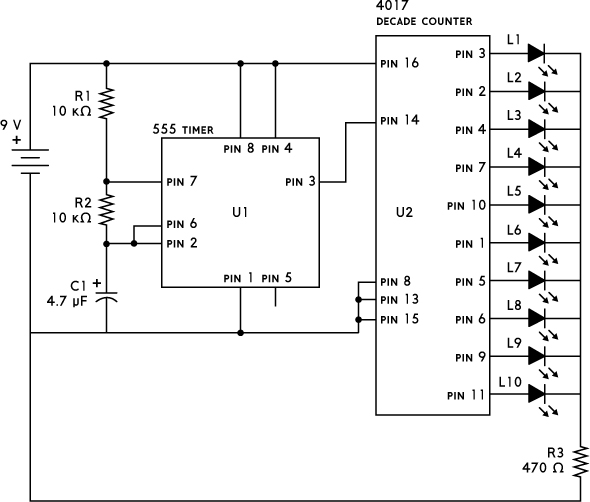
This circuit uses a 555 timer and a 4017 decade counter, both integrated circuits. The voltage of the 555 timer’s pin 3 switches between high and low repeatedly, as you saw in Project 8. You connect this signal to pin 14 of the 4017 IC, and the 4017 counts the number of times the voltage on pin 14 goes from low to high. The 4017 has 10 outputs—marked Q0 to Q9—that represent this count. For example, after three counts, output Q3 is high, while the others are low. On the 10th count, the counter starts from Q0 again. Figure 9-1 shows the pinout for the 4017 IC.
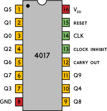
FIGURE 9-1 The pinout for the 4017 IC
The running speed is set by R1, R2, and C1. Change one of the values, and the lights’ running speed will change. Larger values slow it down, and smaller values speed it up.
This is a large circuit, so it’s pretty easy to connect a wire or a component in the wrong place. I suggest you connect only the 555 timer part first. After that, add a 470 Ω resistor in series with an LED between the 555 output on pin 3 and the negative terminal of the battery. You should see the LED blink really fast. When you do, you can disconnect the LED and resistor and continue connecting the rest of the circuit.
This circuit includes a lot of connections in a small area, so you’ll need to be creative with the way you use your space. I recommend you use one of the columns of the left supply area to connect the negative side of the LEDs. This will save you some space.
COMMON MISTAKES
If your circuit isn’t working correctly, check that you haven’t made any of these common mistakes:
- Connecting one or both of the ICs the wrong way
- Mixing up the pin numbers of the ICs and connecting components to the wrong pin
- Connecting one or more of the LEDs in the wrong way
- Connecting the capacitor the wrong way around
- Connecting a wire or component one row above or below where it should be connected
If you’re struggling with this circuit, you can find more resources through the book’s website at https://nostarch.com/circuits/.
HOW THIS CIRCUIT WORKS
This circuit uses a 555 timer to generate a continuous series of pulses (called clock pulses) and a 4017 decade counter to count the number of pulses it receives. LEDs on outputs Q0 to Q9 indicate the count. When the counter reaches 10, it automatically starts from 0 again. This way, it appears as if the LEDs are running from one side to the other, without stopping.
The 4017 IC is easy to use. To get it up and running, just connect the VDD and GND pins to a voltage source. A voltage between 5 V and 15 V will usually work. With the voltage connected, the chip is running and will count any transition from low to high voltage on its CLK (clock) input pin.
Note that each output can provide only about 10 mA of current. If you try to get more current out of each output—for example, by using a smaller resistor value for R3—you risk strange behavior or even chip damage.
The following table provides an overview of each pin’s function.
PIN # |
NAME |
DESCRIPTION |
1 |
Q5 |
Goes high when the count is 5 |
2 |
Q1 |
Goes high when the count is 1 |
3 |
Q0 |
Goes high when the count is 0 |
4 |
Q2 |
Goes high when the count is 2 |
5 |
Q6 |
Goes high when the count is 6 |
6 |
Q7 |
Goes high when the count is 7 |
7 |
Q3 |
Goes high when the count is 3 |
8 |
GND |
Ground (0 V) connection |
9 |
Q8 |
Goes high when the count is 8 |
10 |
Q4 |
Goes high when the count is 4 |
11 |
Q9 |
Goes high when the count is 9 |
12 |
Carry Out |
High output for counts 0 to 4 |
13 |
Clock Inhibit |
Counter does not count any clock pulses when this input is high |
14 |
CLK |
Input for pulses to be counted |
15 |
Reset |
Resets the the count to 0 when high; must be low to count |
16 |
VDD |
Positive voltage supply |