
Chapter 1
Fundamental Functions and Components of Cisco ACI
This chapter covers the following topics related to Cisco Application Centric Infrastructure (ACI):
High-level overview of ACI
Data centers have been hosting business applications for many years, and computer networks have been integral in providing fast communication links for application traffic flows. Applications are driving these growing networks; they are the building blocks that consume and provide the data and are close to the heart of the business life cycle. Organizations must nurture and maintain these expanding networks with large amounts of data flows that are critical for application consumption.
Traditionally, companies have managed the plumbing of application data flow through network devices, and these devices have been managed individually. In the past, application deployment was handled manually, and the process was very slow. The initial application deployment compute, storage, and network requirements were requested by the application team and then by the subsequent infrastructure teams acting on fulfilling a request. With multiple teams working in their own silos, there was often tremendous delay in overall application deployment. The following are some of the granular tasks for application deployment processes hosted through a static infrastructure:
Physical infrastructure (switches, ports, cables, and so on)
Logical topology (VLANs, L2/L3 interfaces and protocols, and so on)
Access control configuration (permit/deny ACLs) for application integration and common services
Services integration (load balancing, firewalls, and so on)
Connecting application workloads (physical servers, VMs, containers, and so on)
Quality of service (QoS) configuration
Multicast configuration
Management and device access control protocol configuration
With this statically defined process, the application hosting cycle could take six months or more; although that was often acceptable to organizations in the past, it does not work well today. One of the roadblocks in application deployment was physical bare-metal servers. Server virtualization was a natural evolution in the effort to decouple workloads from hardware and to make the compute platform scalable and more agile; cramming many virtual machines onto a single physical server also provided huge cost savings. Server virtualization enables an organization to increase utilization of its server hardware to as much as 80%, which is a substantial increase over the 10% to 15% utilization available with bare-metal servers. Despite the advantages of server virtualization, large enterprises still face some challenges as teams often still work in silos in a typical application deployment cycle workflow, as depicted in Figure 1-1.
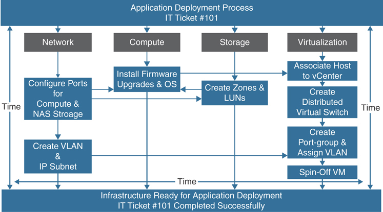
Figure 1-1 Application Deployment Tasks Flow
Server virtualization has brought challenges related to workload mobility as excessive east–west traffic in a traditional three-tier (core, aggregation, edge) network infrastructure results in instability for traditional data center networks as they scale. In addition, businesses have become highly dependent on applications hosted in data centers as e-commerce and cloud are becoming more and more critical to businesses. With the legacy way of deploying networks, compute and storage end up delaying overall application deployment and become pain points for business growth. Companies that provide service offerings to customers through application agility enable those customers to survive in this fast-paced and challenging global economy.
Cloud computing offers organizations the opportunity to increase competitiveness and improve agility. Organizations in all industry-specific market segments are therefore turning to cloud solutions to accelerate innovation, expand market reach, and reduce IT costs. However, embracing cloud solutions presents some challenges. End users often demand that IT departments quickly and flexibly offer services that can help them get their jobs done. Many IT teams struggle to maintain the business services needed to help ensure that end users remain productive and on time. Some of the challenges they face in helping ensure the uptime of critical business services include the following:
A manual service mapping process that can take weeks or months, depending on service complexity
Lack of correlation between infrastructure changes and the business services they support
Disconnected infrastructure tools and portals for change management and troubleshooting
Insufficient monitoring capabilities, which results in inefficient root-cause analysis and extended service outages
Cisco sought to innovate how this infrastructure is governed. It accomplished this by introducing a new paradigm based on an automated policy-based model. Using a policy-based model allows an organization to define a policy and the infrastructure to automate the implementation of the policy into the hardware components. This holistic systems-based approach to infrastructure management speeds up the application development and deployment process with efficient use of infrastructure.
Because application agility is critical for business growth, Cisco named its innovative new paradigm Application Centric Infrastructure (ACI). ACI is a holistic systems-based approach to infrastructure management with new ways of operating the network fabric and the devices that provides application services within it. ACI uses a horizontally elongated leaf/spine architecture with one hop to every end host in a fully meshed ACI fabric in place of the traditional three-tier (core, aggregation, edge) architecture. Highly scalable data forwarding methods are incorporated into ACI fabric to deploy a large number of network segments for virtualized endpoints. Aside from ensuring the physical connectivity (such as port, VLAN, and IP address) of endpoints on network devices, ACI also applies the application logic by grouping these endpoints together to apply security and QoS policies and organizing them in application profiles. In this way, the physical infrastructure is decoupled from application logic, regardless of any kind of workload connectivity requirements. Another efficient forwarding mechanism that ACI initially employed is the Anycast Gateway feature. Each endpoint group carrying the specific subnet when attached to a physical port of the ACI leaf switch programmed the Anycast Gateway feature for that application subnet. This helped tremendously during virtual machine moves anywhere in the ACI fabric. Figure 1-2 illustrates this topology.
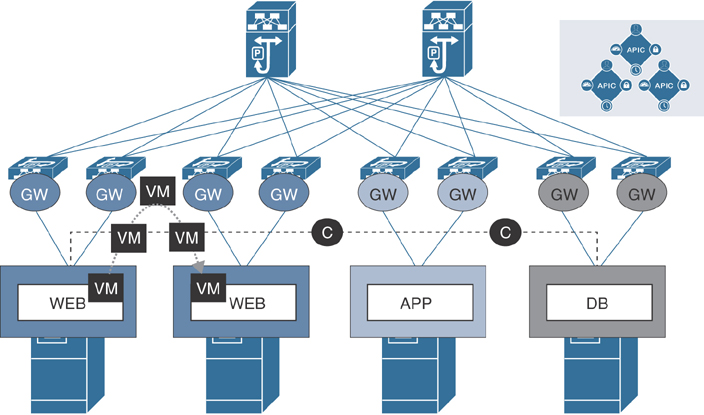
Figure 1-2 ACI Application Logic
Old-school network engineers initially resisted this cultural change of defining network logic created, but then the ease of configuration and availability provided by Cisco ACI won over even the holdouts. Immediate knowledge of the state of the network for a specific application is key to minimizing return-to-service timeframes, ensuring proactive maintenance, and eliminating the once-common help desk “Why is my application response time so slow?” calls. With ACI, the integration goes to the virtualization layer and thus provides full visibility into the workload running on a virtual machine. IT staff with appropriate access can determine if there is a fault in the fabric all the way up to the endpoint, and they can see what type of fault it is and when it occurred. They can then either remediate the issue quickly or emphatically state that the issue is not in the ACI fabric. Let’s consider an example of a three-tier application running on a virtual machine hosted on multiple hypervisors. Figure 1-3 compares the connectivity of hosts in a legacy network and in the ACI fabric.
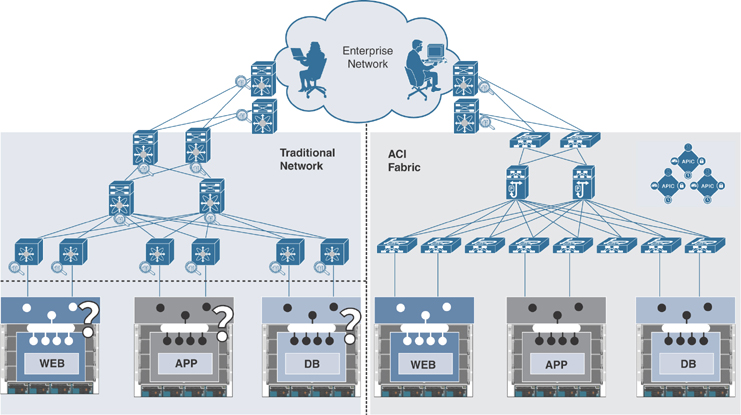
Figure 1-3 Three-Tier Application Hosted in ACI Fabric
As shown on the left side of Figure 1-3, in a legacy network, you need to monitor the performance statistics on each network hop between hosts to check any network bottlenecks. A network engineer was limited to seeing the switches at the edge of the network through which physical hosts were connected and was not allowed to go further down into the virtual networking layer, as another team maintained it. Therefore, in such cases the network engineer had to rely on the performance data from the virtualization team. This lack of integration and visibility between the network infrastructure and the virtual compute infrastructure often resulted in unnecessary finger pointing and conflicts between silo teams, as well as lengthy outages and performance degradation.
Hosting the same three-tier application in ACI through virtual machine manager (VMM) integration provides the benefit of speedy application deployment and end-to-end visibility of the workload when performance or connectivity issues surface. (VMM integration in ACI is explained in detail in Chapter 6, “VMM Integration,” and end-to-end workload visibility and troubleshooting are explained in detail in Chapter 14, “The ACI Visibility & Troubleshooting Tool.”)
The goal and objective of ACI is to enable business growth and rapid application development by providing the following:
Application-driven policy modeling
Centralized policy management
Visibility into infrastructure and application health
Automated infrastructure configuration
Integrated physical and virtual infrastructure workloads
An open interface to enable flexible software and ecosystem partner integration
Seamless communication between endpoints, using optimized forwarding and security enforcement
Multi-cloud networks built with a consistent policy model
When deploying ACI, two design philosophies can be implemented individually or together:
Network centric: With a network-centric design, full understanding of application interdependencies is not critical; instead, the legacy model of a network-oriented design is maintained by mapping each VLAN to an endpoint group (EPG) and a bridge domain (BD). This can take one of two forms:
L2 fabric: The L2 fabric leverages the Application Policy Infrastructure Controller (APIC) to automate provisioning of network infrastructure based on L2 connectivity between connected network devices and hosts.
L3 fabric: The L3 fabric leverages the APIC to automate provisioning of network infrastructure based on L3 connectivity between connected network devices and hosts.
Application centric: An application-centric design takes full advantage of all the ACI objects to build out a flexible and completely automated infrastructure that includes L2 and L3 reachability, physical and virtual machine connectivity, service node integration, and full policy object manipulation and security.
Security is always a major concern in company networks. Cisco ACI addresses security concerns through a whitelist policy model. This means nothing can communicate unless policy allows it. This might prompt you to think a firewall is involved, but although the ACI whitelist model does change the paradigm, it is only analogous to access control lists within a switch or router. However, there is still a need to have protocol inspection and monitoring, which firewalls and intrusion prevention systems (IPSs) do very well. ACI handles the forwarding and ACL-based security and leaves protocol inspection and monitoring to the firewalls and IPSs. Security devices such as firewalls, IPSs, and detection systems (IDSs) can still be implemented within ACI via a services graph, even in Network Policy mode.
The manual configuration and integration work that used to be required are now automated in ACI based on policy, therefore making the infrastructure team more efficient and agile. Instead of manually configuring VLANs, ports, and access lists for every device connected to the network, the team can create the policy and allow the infrastructure itself to resolve and provision the relevant configuration either on demand or immediately, depending on the requirements.
Cisco ACI follows a model-driven approach to configuration management. This model-based configuration is disseminated through the managed nodes using the concept of promise theory, which Mark Burgess proposed in 2004 as a way to resolve issues in obligation-based computer management schemes for policy-based management. (Burgess later wrote the book Promise Theory: Principles and Applications in collaboration with Jan Bergstra.) Promise theory is a management model in which a central intelligence system declares a desired configuration “end state,” and the underlying objects act as autonomous intelligent agents that can understand the declarative end state and either implement the required change or send back information on why it could not be implemented.
In ACI, the intelligent agents are specially built elements of the infrastructure that are active in its management by fulfilling promises. A management team can create an abstract end state model and the system to automate the configuration. The configuration is defined on the ACI controller, which resolves to hardware-level programming on the ACI fabric switches. The idea is that if the configuration could not be deployed, the APIC would be notified of this for reporting purposes. With this model, it is easier to build and manage networks of all sizes with less effort.
Many new ideas, concepts, and terms come with the coupling of ACI and the declarative model. When it comes to automated policy-based network architectures, it is very common to hear about declarative and imperative models, and it is good to understand them:
Declarative model: The declarative model is the orchestration model in which control is distributed to intelligent devices based on centralized policies. It focuses on what the desired state of the network would be. Consider an example of declarative model architecture using the OpFlex protocol, as in the case of ACI or any other modern DevOps IT automation tool: A controller would instruct the network devices to set high priority on traffic while dropping certain traffic. The controller does not need to know how the devices actually fulfill these instructions.
Imperative model: The imperative model focuses on how to achieve the desired state. For example, a controller would explicitly tell a switch how to handle network traffic.
This book is intended to provide advanced-level monitoring and troubleshooting guidelines and best practices.
ACI Building Blocks
Cisco ACI is a software-defined networking (SDN) solution that integrates with both software and hardware. Whereas Cisco competitors offer SDN solutions that work only in software, ACI allows for creating policies in software and using hardware for forwarding, which is an efficient and highly scalable approach that offers better performance. The hardware for ACI is based on the Cisco Nexus 9000 platform product line. The software is driven through the APIC centralized policy controller, which stores all configuration and statistical data. To provide high scalability and deal with excessive east–west traffic flows, Cisco created the Clos architecture. ACI constitutes a two-tier leaf/spine fabric where each end host is one hop away from another host in a full mesh topology, as illustrated in Figure 1-4.
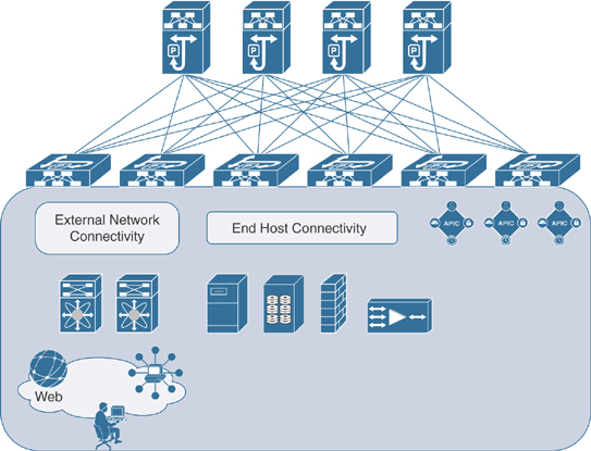
Figure 1-4 ACI Topology
Hardware Specifications
Hardware is the foundation of any computer system technology. Cisco ACI relies heavily on hardware, using state-of-the-art ASICs specifically designed to outperform its competitors in SDN. The hardware that the ACI fabric is built on is the Nexus 9000 product line.
Nexus 9000 Platform
The Nexus 9000 Series delivers proven high performance, port density, low latency, and exceptional power efficiency in a range of form factors. The switches are highly programmable for industry-leading SDN and data center automation. The Nexus 9000 Series provides investment protection with a range of multi-speed ports, such as 1/10/25/50/100/400 Gbps and also unified port capabilities supporting 10/25 Gbps and 8/16/32 Gbps fiber channel, RDMA over converged Ethernet (RoCE), and IP storage. The Nexus 9000 platform delivers industry-standard security and visibility with streaming telemetry, advanced analytics, and line-rate encryption (MACsec). Application performance is 50% faster in terms of completion time, with intelligent buffers and lossless Ethernet capabilities. The Nexus 9000 product line can operate in standalone NX-OS mode and ACI mode. The newer cloud-scale ASIC enables ACI leaf/spine architecture and NX-OS Virtual Extensible LAN (VXLAN) fabrics with a diverse modular and fixed portfolio. In ACI, the Nexus 9000 product line consists of the Nexus 9500 and Nexus 9300 platforms.
Note
In this book, only the cloud-scale Nexus 9000 platform is covered in examples of monitoring and troubleshooting scenarios.
Nexus 9500
Nexus 9500 devices are primarily used as spines (except for the Nexus 9336PQ and Nexus 9364C devices, which can also be used as spines in smaller-scale environments). The Cisco Nexus 9500 Series switches have a modular architecture that comes in 4-, 8-, and 16-slot models and consists of switch chassis, supervisors, system controllers, fabric modules, line cards, power supplies, and fan trays. Among these parts, supervisors, system controllers, line cards, and power supplies are common components that can be shared among the entire Nexus 9500 product family.
The Cisco Nexus 9500 fabric modules and line cards are physically interconnected through direct attachment with connecting pins. Line cards are inserted horizontally, and fabric modules are inserted vertically, giving line cards and fabric modules orthogonal orientations in the chassis so that each fabric module is connected to all line cards and vice versa. This direct attachment of line cards to fabric modules alleviates the need for a switch chassis midplane and is a unique design that Cisco came up with in the Nexus 9500 platform for proper air cooling and circulation. Figure 1-5 shows the orthogonal interconnection of line cards and fabric modules and the midplane-free chassis of a Cisco Nexus 9500 platform switch.

Figure 1-5 Cisco Nexus 9500 Line Card and Fabric Module Interconnection
Line cards include physical ports based on twisted-pair copper for 1/10 Gbps and on SFP and QSFP for 1/10/25/40/50/100 Gbps port speeds. All ports are at line rate, and there are no feature dependencies by card type other than the software code they operate under. Some (94xx, 95xx, 96xx, 97xx Series) are NX-OS only, some (97xx Series) are ACI spine only; at this writing, the newest cards are the 97xx (EX and FX) Series, which supports both software modes (NX-OS and ACI) but not simultaneously. There are also three different models of fabric modules, based on scale: FM, FM-S, and FM-E. If your design requires 100 Gbps support, FM-E is the fabric module for your chassis. The latest cloud-scale modules (EX/FX) in the Nexus 9500 platform supporting ACI mode are as follows:
The N9K-X9736C-FX 36-port 100 Gigabit Ethernet Quad Small Form-Factor Pluggable 28 (QSFP28) line card is shown in Figure 1-6.

Figure 1-6 Cisco Nexus 9736C-FX Line Card for the Nexus 9500 Platform
The N9K-X9732C-EX 32-port 100 Gigabit Ethernet QSFP28 line card is shown in Figure 1-7.

Figure 1-7 Cisco Nexus 9732C-EX Line Card for the Nexus 9500 Platform
Nexus 9300
Nexus 9300 platform devices are primarily used as leaf switches; however, the Nexus 9336PQ, Nexus 9364C, and Nexus 9332C devices can be used as only spines in smaller-scale environments. The Nexus 9300 is a fixed-chassis form factor. Nexus 9300 devices are capable of forwarding L2/L3 at line rate and support VTEP operations for VXLAN and IGP routing protocols such as BGP, OSPF, EIGRP, Multicast, anycast gateways, and so on. The Nexus 9300 comes with different flavors of 1/10 Gbps port speeds with twisted-pair and 1/10/25/40/50/100 Gbps port speeds with SFP/QSFP. The latest cloud-scale models of Nexus 9300 are as follows:
The 93180LC-EX 1 RU with 24 × 40/50 Gbps Quad Small Form-Factor Pluggable Plus (QSFP+) ports and 6 × 40/100 Gbps QSFP28 uplink ports is shown in Figure 1-8.

Figure 1-8 Cisco Nexus 93180LC-EX
The 93180YC-EX 1 RU with 48 × 1/10/25 Gbps Small Form Pluggable Plus (SFP+) ports and 6 × 40/100 Gbps QSFP28 uplink ports is shown in Figure 1-9.
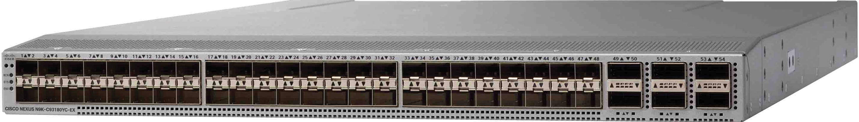
Figure 1-9 Cisco Nexus 93180YC-EX
The 93108TC-EX 1 RU with 48 × 1/10GBASE-T Ethernet ports, which can operate at 100 Mbps, 1 Gbps, and 10 Gbps speeds, and 6 × 40/100 Gbps QSFP28 uplink ports is shown in Figure 1-10.

Figure 1-10 Cisco Nexus 93108TC-EX
The 93180YC-FX 1 RU with 48 downlink ports, which can work as 1/10/25 Gbps Ethernet or FCoE ports or as 8/16/32 Gbps Fiber Channel ports, and 6 × 40/100 Gbps QSFP28 uplink ports is shown in Figure 1-11.

Figure 1-11 Cisco Nexus 93180YC-FX
The 93108TC-FX 1 RU with 48 downlink ports that can work as 100 Mbps or 1/10 Gbps TP Ethernet ports, and 6 × 40/100 Gbps QSFP28 uplink ports is shown in Figure 1-12.

Figure 1-12 Cisco Nexus 93108TC-FX
The 9348GC-FXP 1 RU with 48 downlink ports, which can work as 100 Mbps or 1 Gbps TP Ethernet ports, and four 1/10/25 Gbps SFP28 ports and two 40/100 Gbps QSFP28 uplink ports, is shown in Figure 1-13.
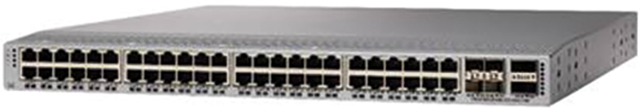
Figure 1-13 Cisco Nexus 9348GC-FXP
The 9336C-FX2 1 RU with 30 downlink ports, which can work as 10/40/100 Gbps QSP28 ports, and 6 × 40/100 Gbps QSFP28 uplink ports, is shown in Figure 1-14.
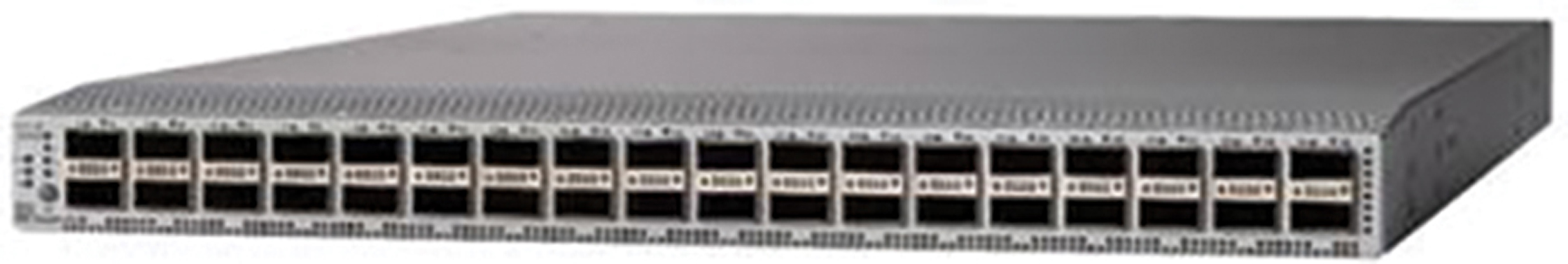
Figure 1-14 Cisco Nexus 9336C-FX2
Note
The details provided here are current as of this writing. For the latest updates on Nexus 9000 platform specifications, visit cisco.com.
APIC Controller
The Cisco APIC is the brain of the ACI solution. It is a software controller in the ACI fabric that runs on a Cisco UCS C220 1 RU standalone server. APICs are grouped together to form a cluster with a minimum of three controllers that can be extended to up to seven controllers, depending on the fabric scale. Typically high availability is established with an even number of hardware devices rather than odd. However, with ACI, all policies, logs, and statistical data are stored in a database on APIC controllers. That database breaks up the elements of a policy into data blocks called shards. The APIC distributes the shards into multiples of three copies to other APICs in the cluster.
The APIC controller is built on a Representational State Transfer (REST) architecture-based programmatic interface that is fully exposed northbound to end-users and set through Extensible Markup Language (XML) and JavaScript Object Notation (JSON), providing consumers with a rich set of tools to configure and operate an ACI fabric. The command-line interface (CLI) and web user interface (UI) operate as a wraparound on top of REST. An APIC provides the following benefits:
A single pane of glass for application-centric network policies
Fabric image management and inventory
Application, tenant, and topology monitoring
Troubleshooting
Unlike most industry SDN solutions, where a controller takes part in data forwarding by configuring flow forwarding rules, an APIC is not on the data path in ACI. This means the fabric network devices are fully capable of making traffic-forwarding decisions even when direct communication with the APIC is lost. The Cisco UCS C-Series server on which an APIC runs comes in two Large (L1 or L2) and Medium (M1 or M2) device specifications to cater to various ACI fabric sizes. An APIC consists of a VIC 1225 CNA PCIe card that has 2 × 10 Gbps interfaces (SFP+ or twisted-pair). These interfaces are part of the ACI fabric through which all policies get pushed to nodes (leafs/spines). A Cisco APIC is connected to two different leafs for redundancy using these interfaces. Aside from the VIC 1225 card, the APIC controller also consists of two 1 Gbps (twisted-pair) management ports, which must be connected to an out-of-band management network. The APIC is accessed through these management interfaces for managing the ACI fabric. Both the VIC 1225 and management interfaces at the back of the chassis function as a bond interface with active/standby status inside APIC software.
Note
The first and second generation of APICs (L1 and L2 or M1 and M2) are end of sale. They have been replaced with third-generation APIC controllers (L3 or M3), each of which contains a VIC 1445 quad-port 10/25 Gbps SFP28 CNA PCIe card. Note that third-generation L3/M3 APICs require APIC code 4.x or later.
An APIC has two power supplies, display, and USB KVM and console ports at the back. An APIC is a server, and Cisco UCS servers use Cisco Integrated Management Controller (CIMC) to remotely manage an APIC without being physically present in the data center. The front of the chassis has a power button, status LEDs, hard disks, and a KVM port that can be used via a dongle (see Figure 1-15).

Figure 1-15 Cisco APIC Front and Rear Views
ACI Key Concepts
For the most part, the network concepts for Cisco ACI are the same as for other solutions deployed over the past several years in corporate data centers. ACI is different, however, in the management and policy framework, along with the protocols used in the underlying fabric.
Leaf switches provide end-host connectivity, and spines act as a fast non-blocking Layer 3 forwarding backplane that supports equal-cost multipathing (ECMP) between any two endpoints in the network but uses overlay protocols such as VXLAN under the hood to allow any workload to exist anywhere in the network. Supporting overlay protocols enables the fabric to have workloads, either physical or virtual, in the same logical network (Layer 2 domain), even while running Layer 3 routing down to the top of each rack. The VXLAN overlay is deployed on an Intermediate System-to-Intermediate System (IS-IS) underlay, where each ACI switch advertises reachability to each of the other VXLAN-enabled interfaces. This underlay is specifically built to be scalable as more links are added to the Cisco Clos topology, as well as resilient to failure when links are brought down. In addition, ACI switches dynamically build a multicast distribution tree (MDT) that is used to send flood traffic for certain protocols. The MDT ensures that this can be done without creating a loop in the overlay network.
From a management perspective, the APIC manages and configures the policy on each of the switches in the ACI fabric. Hardware becomes stateless with Cisco ACI. This means no configuration is tied to the network device (leaf or spine). The APIC acts as a central repository for all policies and has the capability to rapidly deploy and redeploy hardware, as needed, by using this stateless computing model.
Cisco ACI also serves as a platform for other services that are required within the data center or cloud environment. Through the use of the APIC, third-party services can be integrated for advanced security, load balancing, and monitoring. Vendors and products such as Cisco ASA, Cisco Firepower, F5, Palo Alto, and Citrix can integrate natively into the ACI fabric and be part of the policy framework defined by the administrator. Through the use of northbound APIs on the APIC, ACI can also integrate with different types of cloud environments.
ACI is an SDN architecture from Cisco that uses a policy-based approach to abstract traditional network constructs such as VLANs, VRF instances, and IP subnets and build an application tier with security policies. This chapter describes various basic concepts of ACI at a high level. For in-depth understanding of each of the components of ACI, refer to the Cisco Press book Deploying ACI: The Complete Guide to Planning, Configuring, and Managing Application Centric Infrastructure.
Control Plane
For control plane protocols, ACI uses standard protocols that have been used in the industry for many years, such as IS-IS and MP-BGP EVPN. As an ACI fabric is instantiated, each new leaf or spine attached to the fabric uses a specific Type-Length-Value (TLV) setting in an LLDP PDU to discover the remaining fabric members. This allows the ACI administrator to join the newly connected switches to the ACI fabric.
ACI uses VXLAN as the data plane protocol, so each node (leaf/spine) is assigned a unique IP address called the VXLAN Tunnel Endpoint (VTEP) address. This address is added dynamically via the APIC controller. Forwarding across VTEPs is achieved via a single-area IS-IS configuration, which enables massive scale as well as simplicity.
For the control plane protocol, as mentioned earlier, ACI uses IS-IS, and it also uses MP-BGP to advertise prefixes inside and outside the ACI fabric via special leafs called border leafs. To configure BGP, you just need to assign one or more spines as BGP route reflectors to establish an iBGP mesh inside the fabric.
ACI also uses Council of Oracle Protocol (COOP) for efficient endpoint learning and optimized forwarding inside the fabric. All spines within the ACI fabric store endpoint information and synchronize with their fellow spines to track elements attached to the fabric via the leaf. COOP uses ZeroMQ to achieve this control plane communication and leverages MD5 authentication to protect from malicious attacks.
OpFlex is another new control plane protocol used in ACI designed to communicate policy intent from the APIC controller. It is used to communicate policy between the APIC and the end devices that support that protocol. OpFlex also allows for ACI policy to reach into the fabric hardware (leaf/spine) to enforce policy defined on the APIC.
Next we will look at the control plane protocols IS-IS and COOP to better understand the basics of how ACI forwards traffic between endpoints. (For more details on ACI forwarding, see Chapter 12, “Bits and Bytes of ACI Forwarding.”)
Figure 1-16 shows an example of a simple ACI topology with two leafs, two spines, and a APIC controller.

Figure 1-16 ACI Control Plane Sample Topology
This sample topology has two leafs, two spines, and an APIC connected in the Clos architecture forming ACI fabric. Spine 101 has VTEP address 20.20.20.101. Spine 102 has VTEP address 20.20.20.102. Leaf 201 and Leaf 202 have VTEP addresses 20.20.20..201 and 20.20.20.202. There are two end hosts connected to Leafs 201 and 202. Server 1, with MAC address 0000.0000.001A and IP address 100.100.100.1, is connected to Leaf 201 port Eth1/1. Similarly, Server 2 with MAC address 0000.0000.002B and IP address 100.100.100.2 is connected to Leaf 202 port Eth1/1.
Say that Server 1 wants to talk to Server 2. Server 1 sends an ARP request to its directly connected Leaf 201, in search of Server 2’s location (the MAC address of Server 2). Leaf 201 then knows that Server 1 is connected to its local port Eth1/1 with MAC address 0000.0000.001A and, most importantly, IP address 100.100.100.1. It stores this information in its local station table (LST) and forwards the information to one of the two equally cost connected spines (randomly picked) using COOP. The spine that is picked with this information stores it in its global proxy table and shares that information with other spines in the fabric. Similarly, on the Server 2 side, the same processes have resulted in learning the MAC and IP addresses of Server 2 at some point through ARP. Hence, COOP stores the information of all endpoints connected in the entire ACI fabric on all spines; this information is provided by leafs. This setup provides optimized communication between endpoints without the need for the traditional ARP flooding in the fabric (although that is also available if enabled in the configuration for legacy network connectivity).
VTEPs are used to reach every node (leaf and spine), and these VTEP addresses are distributed by a very lightweight routing protocol under the hood. This protocol is instantiated as soon as a fabric node (leaf/spine) joins the fabric. IS-IS provides this capability to every leaf as it has equal-cost paths to reach other leafs via spines. (Cisco used the same IS-IS protocol to distribute fabric path IDs in fabric path configuration on Nexus 7000/5000 platform devices in the past.)
Data Plane
The IETF standard VXLAN is commonly used as data plane protocol in modern data centers where scalability is an issue. Cisco ACI has adopted VXLAN as its data plane protocol with the modification of leveraging the reserved bits for intelligent forwarding inside the fabric; and the ACI version of VXLAN is called iVXLAN (based on the earlier product name Insieme). In ACI, VXLAN is programmed in hardware on the Nexus 9000 platform for efficient performance and throughput. VXLAN offers the ability to provide L2 and L3 separation using a shared physical medium.
The use of VXLAN is prevalent across the ACI fabric, within the spines and leafs and even within various virtual switch elements attached to the fabric, such as the Cisco ACI Virtual Edge.
VXLAN
VXLAN is designed to provide the same Ethernet Layer 2 network services as a VLAN does today but with greater extensibility and flexibility. Compared to a traditional VLAN, VXLAN offers the following benefits:
Flexible placement of multitenant segments throughout the data center: It provides a solution to extend Layer 2 segments over the underlying shared network infrastructure so that the tenant workload can be placed across physical pods in the data center.
Higher scalability to address more Layer 2 segments: VLANs use a 12-bit VLAN ID to address Layer 2 segments, which limits scalability of only 4094 VLANs. VXLAN uses a 24-bit segment ID known as the VXLAN network identifier (VNID), which enables up to 16 million VXLAN segments to coexist in the same administrative domain.
Better utilization of available network paths in the underlying infrastructure: VLANs require Spanning Tree Protocol for loop prevention, which ends up not using half of the network links in a network by blocking redundant paths. In contrast, VXLAN packets are transferred through the underlying network based on its Layer 3 header and can take advantage of Layer 3 routing and ECMP routing to use all available paths.
VXLAN is a Layer 2 overlay scheme over a Layer 3 network. It uses MAC-in-UDP encapsulation to provide a means to extend Layer 2 segments across the data center network. VXLAN uses MAC-in-UDP encapsulation instead of MAC-in-GRE because Cisco’s other overlay technologies, such as OTV and LISP, also use MAC-in-UDP instead of MAC-in-GRE. In reality, the vast majority of (if not all) switches and routers do not parse deeply into GRE packets for applying policies related to load distribution (port channel and ECMP load spreading) and security (ACLs). VXLAN is a solution that supports a flexible, large-scale multitenant environment over a shared common physical infrastructure. IP and UDP are the transport protocols over the physical data center network.
VXLAN defines a MAC-in-UDP encapsulation scheme in which the original Layer 2 frame has a VXLAN header added and is then placed in a UDP/IP packet. With this MAC-in-UDP encapsulation, VXLAN tunnels a Layer 2 network over a Layer 3 network. Figure 1-17 illustrates the VXLAN packet format.

Figure 1-17 VXLAN Packet Format
Tenant
A tenant is a logical container that houses all application-related policies and constructs. It enables an administrator to exercise domain-based access control within an organization. A tenant represents a unit of isolation from a policy perspective, but it does not represent a private network. A tenant can represent a customer in a service provider environment, a department or division in an enterprise, or just a convenient grouping of policies. Figure 1-18 provides an overview of a tenant object and its relationship with other objects.

Figure 1-18 Tenant
Tenants can be isolated from one another or can share resources. The primary elements that a tenant contains are filters, contracts, outside networks, bridge domains, virtual routing and forwarding (VRF) instances, and application profiles that contain endpoint groups (EPGs). Entities in the tenant inherit the tenant’s policies.
In an ACI fabric, you can create multiple tenants based on your business requirements. You must configure a tenant before you can deploy any other application-related configuration.
VRF
A VRF instance, also known as a context, is a tenant network (called a private network in the APIC GUI). A tenant can have multiple VRF instances. A VRF instance is a unique Layer 3 forwarding and application policy domain. Figure 1-19 shows the relationship of a VRF instance to other objects under the tenant configuration.

Figure 1-19 VRF Instance
A VRF instance defines a Layer 3 address domain. One or more bridge domains are associated with a VRF instance. All the endpoints within the Layer 3 domain must have unique IP addresses because it is possible to forward packets directly between these devices if the policy allows it.
Application Profile
An application profile defines the policies, services, and relationships between EPGs. Figure 1-20 shows the relationship of the application profile to other objects in the tenant configuration.
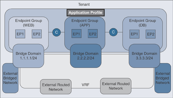
Figure 1-20 Application Profile
An application profile acts as a folder that contains one or more EPGs. Modern applications contain multiple components. For example, an e-commerce application could require a web server, a database server, data located in a storage area network, and access to outside resources that enable financial transactions. The application profile contains as many (or as few) logically related EPGs as necessary to provide the capabilities of an application.
EPGs can be organized according to one of the following:
The application they provide, such as a DNS server or SAP application
The function they provide (such as infrastructure)
Where they are in the infrastructure of the data center (such as DMZ)
Whatever organizing principle a fabric or tenant administrator chooses to use
Endpoint Group
The most commonly asked question related to ACI is “What is an EPG, and how is it used within ACI?” The basic idea is that you define groups of servers, virtual machines, IP storage, or other devices that have common policy requirements. Once those devices are grouped together, it becomes much easier to define and apply policy to the group rather than to individual endpoints.
ACI EPGs provide a new model for mapping applications to the network. Rather than using VLANs or subnets to apply connectivity and policy, policy is defined on an EPG, and ports are assigned to it. Using this concept, an administrator no longer needs to statically apply networking requirements such as ACLs or QoS on a per-port basis. Instead, the policy is applied once at the EPG level, and then interfaces are added to that EPG. The APIC then ensures that the policy is pushed to those interfaces, which decreases deployment time and change control dramatically. EPGs are then associated with a bridge domain to provide the Layer 2 forwarding boundary for the connected devices. Now the security and forwarding are automated by the APIC, which simplifies the deployment process.
Imagine that you have a standard three-tiered application like the one depicted in Figure 1-21.
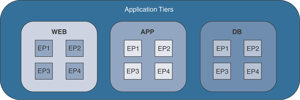
Figure 1-21 Standard Three-Tiered Application
Within each of the application tiers, a number of endpoints can be either bare-metal or virtualized workloads. The important thing is that these endpoints all require the same policy to be applied. If you can identify which group these endpoints need to be part of, you can create the corresponding EPGs within ACI (refer to Figure 1-18).
How do you define which endpoints reside in which EPG? You can do so by either statically or dynamically attaching to an EPG with either physical or virtual domains, depending on the computer characteristics. If these are VMs, then ACI can integrate closely with the VMM (such as vCenter), and the process of attaching a VM to a network results in that VM becoming part of the desired EPG. When you have EPGs defined and endpoints residing within them, what comes next? At this point, there are two important concepts to understand:
Within an EPG, communication is free-flowing by default. An endpoint can communicate freely with another endpoint within the same EPG, regardless of where those endpoints reside.
Between EPGs, no communication is permitted by default. If you do nothing else at this point, an EP residing in the Web EPG will not be able to communicate with an EP in the App EPG.
Now that you know these rules, you need to understand how traffic is allowed to flow between endpoints that are in different EPGs. This is where contracts and filters come into the picture; you will learn more about in the next section. Figure 1-22 illustrates the EPGs and how endpoints communicate via contracts.
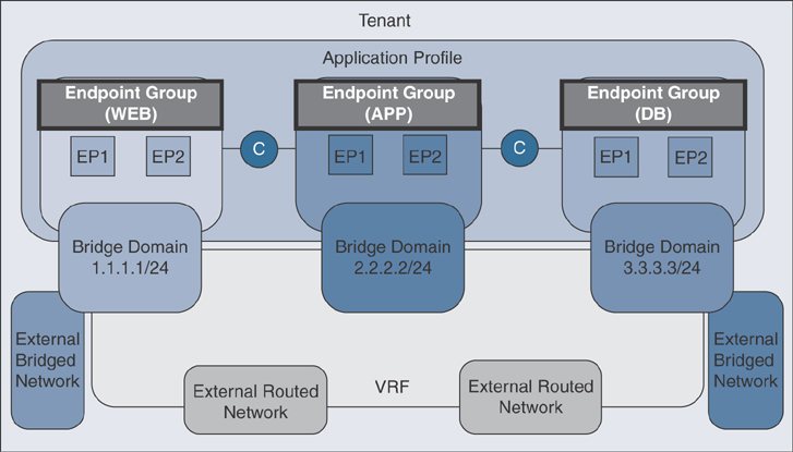
Figure 1-22 Endpoint Group
Contracts
In addition to EPGs, contracts are key objects in the policy model. EPGs can only communicate with other EPGs according to contract rules. Figure 1-23 highlights the locations of contracts and their relationships to other objects in the tenant configuration.

Figure 1-23 Contract
An administrator uses a contract to select the type(s) of traffic that can pass between EPGs, including the protocols and ports allowed. If there is no contract, inter-EPG communication is disabled by default. There is no contract required for intra-EPG communication; intra-EPG communication is always implicitly allowed, with the exception of micro-segmentation use cases.
You can also configure contract preferred groups that enable greater control of communication between EPGs in a VRF. If most of the EPGs in a VRF should have open communication, but a few should have only limited communication with other EPGs, you can configure a combination of a contract preferred group and contracts with filters to control communication precisely. Contract preferred groups allow two or more EPGs to communicate freely, as if they are part of the same EPG. EPGs outside the preferred group require a contract to communicate.
Contracts govern the following types of EPG communications:
Between ACI fabric application EPGs, both intra-tenant and inter-tenant
Between ACI fabric application EPGs and Layer 2 external outside network instance EPGs
Between ACI fabric application EPGs and Layer 3 external outside network instance EPGs
Between ACI fabric out-of-band or in-band management EPGs
Contracts govern the communication between EPGs that are labeled providers, consumers, or both. EPG providers expose contracts with which a would-be consumer EPG must comply. An EPG and a contract can have either a provider relationship or consumer relationship. When an EPG provides a contract, communication with that EPG can be initiated from other EPGs, as long as the communication complies with the provided contract. If you were to compare a contract to a traditional access list, the consumer would be the source, and the provider would be the destination. However, when an EPG consumes a contract, the endpoints in the consuming EPG may initiate communication with any endpoint in an EPG that is providing that contract.
Bridge Domain
A bridge domain (BD) is a Layer 2 forwarding construct within the ACI fabric. Figure 1-24 shows the locations of BDs in relationship to other objects in the tenant configuration.

Figure 1-24 Bridge Domain
A BD must be linked to a VRF instance, even if only operating at Layer 2. The BD defines the unique Layer 2 MAC address space and a Layer 2 flood domain, if such flooding is enabled. While a VRF defines a unique IP address space, that address space can consist of multiple subnets. Those subnets are defined in one or more BDs that reference the corresponding VRF.
The options for a subnet under a BD or under an EPG are as follows:
Public: The subnet can be advertised via a routed connection using a dynamic routing protocol.
Private: The subnet applies only within its tenant.
Shared: The subnet can be shared with and exported to multiple VRF instances in the same tenant or across tenants as part of a shared service. An example of a shared service is a routed connection to an EPG present in another VRF in a different tenant. This is sometimes referred to as a “shared L3-out,” and it enables traffic to pass in both directions across VRF instances.
External Routed or Bridged Network
An external routed network extends a Layer 3 construct from ACI to the external network. This configuration is commonly done on a pair of leafs for redundancy; this pair of leafs, called border leafs, is preferably a dedicated leaf pair. The interfaces that connect from border leafs to external routers can be either routed interfaces, routed subinterfaces, or switch virtual interfaces (SVIs). All commonly used routing protocols—such as OSPF, EIGRP, and BGP—along with static routes are supported with external routed network configuration.
Once network adjacency is established between border leafs and external routers, externally learned prefixes are advertised into MP-BGP so that they can be reflected to non-border leafs. This ensures that devices can be connected to any leaf in the fabric, and the route to these prefixes will point to the border leaf.
An external bridged network is sometimes referred to as a Layer 2 outside connection in various Cisco documents. It is one of the options to provide Layer 2 extension from the ACI fabric to an outside network. With an external bridged network you can define policy between your ACI fabric and the external Layer 2 domain.
Outside network policies control connectivity to external networks from ACI fabric. A tenant can contain multiple outside network objects. Figure 1-25 shows the locations of outside networks and their relationships to other objects in the tenant configuration.

Figure 1-25 Outside Network
Outside network policies specify the relevant Layer 2 or Layer 3 properties as well as security policies that control communications between an outside public or private network and the ACI fabric. External devices could be routers such as data center cores or WAN cores or Layer 2 switches during the workload migration phase from a legacy network to ACI. These external devices connect to the front panel interfaces of a leaf switch. A leaf switch that provides such connectivity is known as a border leaf. The border leaf switch interface that connects to an external device can be configured as either a bridged or routed interface. In the case of a routed interface, static or dynamic routing can be used. The border leaf switch can also perform all the functions of a normal leaf switch; however, Cisco’s recommendation is to at least have a pair of dedicated border leafs for redundancy.
Summary
After reading this chapter, you should have a better understanding of ACI technology, its foundation and building blocks, and key concepts of its various components. Without proper understanding of these key concepts of ACI technology, it would be really hard for you to monitor and troubleshoot ACI. In the next chapter you will learn about the ACI policy model.
Review Key Topics
If you are preparing to take the Implementing Cisco Application Centric Infrastructure - Advanced (300-630 DCACIA) exam to attain the Cisco Certified Specialist—ACI Advanced Implementation certification, be sure to review the key topics marked in this chapter as outlined in Table 1-1.
Table 1-1 Key Topics
Key Topic Element |
Description |
Page Number |
Bulleted list |
Network-centric and application-centric design philosophies when deploying ACI. |
Review Questions
The questions that follow are designed to help you prepare for the Implementing Cisco Application Centric Infrastructure - Advanced (300-630 DCACIA) exam if you are planning on acquiring the Cisco Certified Specialist: ACI Advanced Implementation certification.
1. What are the key benefits of ACI compared to traditional networking for hosting applications in data centers? (Choose three options that collectively answer these questions.)
Achieving business agility through rapid deployment of application-hosting infrastructure using automation and orchestration
Filling gaps between various application infrastructure siloed teams (such as network, storage, and virtualization teams)
Rapidly deploying network devices in the data center through automation
Easing virtual machine workloads through the Clos architecture without compromising performance
Eliminating bare-metal servers and increase virtualized compute platforms in Datacenter for high scalability
2. What are the two logical design philosophies ACI uses to efficiently deploy and consume application infrastructure? How can they be adopted? Choose three options that collectively answer these questions.
Multi-pod and multi-site.
Network centric and application centric.
Start your ACI deployment with VLAN-to-EPG mapping through the application centric design model and move down the path of the network centric design model.
The application centric design model provides efficient use of the entire application infrastructure through policy object manipulation and security.
Start your ACI deployment with VLAN-to-EPG mapping through the network centric design model and move down the path of the application centric design model.
Full meshed design and partial meshed design.
3. What protocol does ACI use to discover fabric nodes?
Cisco Discovery Protocol (CDP)
Link Layer Discovery Protocol (LLDP)
Border Gateway Protocol (BGP)
Interior Gateway Protocol (IGP)
4. What are the control plane and data plane protocols used in ACI fabric? What functions do they provide in ACI fabric? Choose two options that collectively answer these questions.
The use of VXLAN protocol provides higher scalability in application workloads through a large number of network segments.
For the control plane, ACI uses IS-IS, MP-BGP EVPN, and VXLAN, and for the data plane, ACI uses COOP and OpFlex.
IS-IS is used to learn endpoints throughout the fabric.
MP-BGP EVPN distributes VXLAN Tunnel Endpoint (VTEP) addresses inside the fabric.
COOP is used to redistribute external routes inside the ACI fabric through a border leaf.
For the control plane, ACI uses IS-IS, MP-BGP EVPN, COOP, and OpFlex, and for the data plane, ACI uses VXLAN.
OpFlex is a Cisco-proprietary protocol used to communicate with APICs.
5. What are the key characteristics of the Cisco ACI VXLAN protocol? (Choose two.)
ACI uses the IETF VXLAN standard (RFC 7348) as the data plane protocol.
VXLAN provides a Layer 3 extension between geographically dispersed data centers.
ACI uses a slightly modified version of the IETF VXLAN standard by using the reserved bits for intelligent forwarding inside the fabric.
VXLAN is a data plane protocol that provides high scalability of network segments using 12-bit IDs.
VXLAN is a Layer 2 overlay mechanism over a Layer 3 network in which an Ethernet frame is encapsulated in a UDP packet.
The ACI VXLAN version uses the MAC-in-MAC method to build a Layer 2 overlay on Layer 3 networks.
VXLAN requires proper configuration of Spanning Tree Protocol for efficient use of redundant fabric links.
6. What is the ACI application logical construct, and how do each of its components relate to each other? (Choose three.)
An application profile is a container that houses application endpoint groups (EPGs).
Security policies are applied on an application profile container to allow traffic flow between multiple applications.
An endpoint group is a collection of endpoints that require similar policies.
A tenant is a Layer 3 forwarding construct inside the ACI fabric.
A contract preferred group further restricts communication between endpoints located in different EPGs.
VRF is used to securely host multiple organization application-hosting infrastructures.
A bridge domain is a Layer 2 forwarding construct in ACI that can contain a subnet that can be local or advertised externally.