
Chapter 5
End Host and Network Connectivity
Now that you have read the first four chapters, you should be well acquainted with the various design options in Cisco Application Centric Infrastructure (ACI). This chapter delves into end host and network connectivity options offered by ACI:
-
Access policies and configuring virtual port channels (VPCs), port channels, and access ports
End Host Connectivity
Thanks to the openness of the ACI architecture, a wide variety of end host and network connectivity options are available, with all sorts of combinations of speed, transceiver, cabling, protocol, and redundancy, in compliance with industry standards. ACI has a connectivity option available for you whether you want to connect bare-metal or virtual compute using standard pizza boxes or blade chassis, connect storage (IP, FCoE), connect a wide range of Layer 2/3 devices such as switches and routers and a variety of Layer 4/7 devices such as load balancers, IP address management devices, firewall devices, and so on.
Because ACI is a policy-based demand and consume model, to provide efficient usage of your application hosting infrastructure, you need to understand some key object components and a defined sequence of steps in creating each of the configuration policies for end host and network connectivity. As mentioned earlier in the book, ACI was designed with multitenancy in mind, and an APIC needs to provide an administrator with a way to restrict which tenants can deploy what resources. The way this is accomplished is by configuring access policies, which define domains (types of end device), pools (VLAN ranges), and who has access to deploy them on the ACI switch interfaces. These components are explained in Chapter 2, “Introduction to the ACI Policy Model,” and this chapter goes over some of the key concepts of access policies and their workflows again as this information is crucial for end host and network connectivity.
VLAN Pool
A VLAN pool contains a VLAN or range of VLANs that are associated with a single or multiple domains and consumed by the endpoint groups (EPGs). VLANs are instantiated on leaf switches based on attachable access entity profile (AAEP) configuration. Allow/deny forwarding decisions are based on contracts and the policy model rather than subnets and VLANs, as was traditionally the case in legacy networks.
Domain
A domain identifies the type of device that will be connecting to the ACI fabric, such as bare-metal, virtualized compute, or any other Layer 2–Layer 7 device. VLAN pools are mapped to domains to specify what VLAN ranges each type of device will have access to. A domain is associated with a single VLAN pool. EPGs are configured to use one or more domains, allowing the EPGs access and mapping to VLANs. Hence, a domain could be physical, virtual, external (bridged or routed), or Fibre Channel.
Attachable Access Entity Profiles (AAEPs)
An AAEP is a conduit between the logical and physical constructs of the ACI fabric configuration and is used to group domains with similar requirements. AAEPs are tied to interface policy groups. One or more domains can be added to an AAEP to allow multiple types of devices to connect on a single interface (such as a blade switch). Grouping domains into AAEPs and associating them enables the fabric to know where the various devices in the domain live, and the APIC can push the VLANs and policy where they need to be. AAEPs are configured in the Global Policies section of the APIC interface.
EPGs are considered the who in ACI, contracts are considered the what/when/why, AAEPs can be considered the where, and domains can be thought of as the how of the fabric. Different domain types are created, depending on how a device is connected to the leaf switch. There are five different domain types:
Physical domains: These domains are generally used for bare-metal servers or virtualized compute, where VMM integration with ACI is not an option.
External bridged domains: These domains are used for Layer 2 connections. For example, an external bridged domain could be used to connect an existing legacy NX-OS switch to an ACI leaf switch.
External routed domains: These domains are used for Layer 3 connections. For example, an external routed domain could be used to connect a WAN router to an ACI leaf switch.
VMM domains: These domains are used when integrating virtual machine controllers or container orchestration tools with the ACI fabric.
Fibre Channel domains: These domains are used for connecting Fibre Channel– and Fibre Channel over Ethernet (FCoE)–enabled devices to the ACI fabric.
Let’s look at some switch and interface policy concepts and configuration. These policies are grouped into two top-level categories: switch policy and interface policy. Furthermore, these policies have subcategories for efficient consumption of resources on the hardware. For example, under interface policy are the subcategories policies, policy groups, and profiles.
Switch Policies
There are certain unique policies for switches, such as policies for configuring VPC domains, which are explicitly called VPC protection groups in the APIC. Ideally, policies should be created once and reused when connecting new devices to the fabric. Maximizing reusability of policy and objects makes Day 2 operations exponentially faster and easier to manage.
Switch Policy Groups
Switch policy groups allow leveraging of existing switch policies such as spanning-tree and monitoring policies.
Switch Profiles
Switch profiles enable the selection of one or more leaf switches and associate interface profiles to configure the ports on a specific node. This association pushes the configuration to the interface and creates an access port, a port channel, or a virtual port channel (VPC) if one has been configured in the interface policy.
Figure 5-1 depicts the workflow between various policies.

Figure 5-1 Relationship Between Logical and Physical Construct in ACI
Interface Policies
Interface policies dictate interface behavior such as link speed, link discovery, port channel, and so on and are also tied to interface policy groups. For example, there could be a policy that dictates whether virtual port channel should use the LACP mode active, passive, or so on or whether an interface should have CDP enabled or disabled; such policies can be reused as new devices are connected to the leaf switches.
Interface Policy Groups
Interface policy groups are templates that dictate port behavior and are associated to an AAEP. Interface policy groups use policies to specify how links should behave. These are also reusable objects, as many devices are likely to be connected to ports that require the same port configuration. There are three types of interface policy groups: access port, port channel, and VPC. The policy group used depends on the link type.
The ports on the leaf switches default to 10 Gigabit Ethernet, and a Gigabit Ethernet link-level policy must be created for devices connected at that speed. Regarding port channels and VPCs, the policy group is what defines the logical identifier (poX) on the switch. Therefore, if you want to create 10 PCs/VPCs, you must create 10 policy groups. Access port policy groups can be reused (which is recommended) between interfaces because there is no logical interface defined. Policy groups do not actually specify where the protocols and port behavior should be implemented. The where happens by associating one or more interface profiles to a switch profile, as discussed in the following section.
Interface Profiles
Interface profiles help glue the pieces together. An interface profile contains blocks of ports called interface selectors and is also tied to the interface policy groups described in the previous section. Again, this is just an arbitrary port, such as e1/1; the profile must be associated with a specific switch profile to configure the ports.
While many policies are reusable, it is important to understand the implications of deleting policies from the ACI fabric. Policy usage can be viewed by clicking the Show Usage button in the APIC GUI when viewing a given object. The information provided can help you determine what objects are using what policy so you can understand the impact when making changes and evaluate whether changes would impact production services.
Access policies enable an administrator to configure port channels and VPCs; protocols such as LLDP, CDP, or LACP; and features such as monitoring and diagnostics. To apply a configuration across a potentially large number of switches, an administrator defines switch profiles that associate interface configurations in a single policy group. In this way, large numbers of interfaces across the fabric can be configured at once. Switch profiles can contain symmetric configurations for multiple switches or unique special-purpose configurations. Figure 5-2 shows the process for configuring access to the ACI fabric.

Figure 5-2 ACI Access Policy Configuration Process
Figure 5-3 shows the result of applying Switch Profile 1001–1002 and Switch Profile 1004 to the ACI fabric.

Figure 5-3 Applying Access Policy Configuration
Notice that the switch profile and interface profile are named in the same way. A recommended way to configure your switch profiles is to create a one-to-one mapping of physical nodes to switch profiles and one switch profile that contains two switches per VPC domain. Using the example in Figure 5-3, there could be four switch profiles created: 1001, 1002, 1004, and 1001–1002. The same interface profiles could be created and mapped to the matching switch profiles. Then, to enable and configure new interfaces on a given switch or VPC, you would simply need to allocate the port block under the interface profile, and the relationship to the appropriate switch or VPC domain would already be defined for you.
This combination of infrastructure and scope enables administrators to manage fabric configuration in a scalable fashion. These configurations can be implemented using the REST API, the CLI, or the GUI. The Quick Start interface in the GUI enables you to automatically create the underlying objects needed to implement such policies.
For physical connectivity of end hosts, you have the option of creating a nonbonded access port and bonded single-chassis or multi-chassis EtherChannel called a VPC. While using the wizards is an excellent way of deploying configuration quickly, it’s always recommended to look at what objects are being created for you. This way, if an issue arises and you need to troubleshoot your configuration, you are familiar with the workflow and can validate the configuration on your own.
Virtual Port Channel (VPC)
VPC technology has been around in the industry for quite some time on Nexus switches. It allows you to create a Multichassis EtherChannel (MEC) where physical links are connected to two different ACI leaf switches to appear as a single logical switch and yet bundle them up for connecting to an end host. This end host could be a server, switch, router, Layer 4/Layer 7 device, or any other networking device that supports link aggregation group (LAG) or Ethernet bundling technology. Cisco developed VPC to pair two Nexus switches together to act as one logical node connecting to an end host and provide redundant links and prevent being blocked by Spanning Tree Protocol. VPC works by joining two switches together into a “VPC domain.” In the VPC domain, one switch is referred to as primary and the other as secondary.
Due to the immense adoption of VPC in the industry today, Cisco ACI includes this technology. However, there are some unique differences in the way Cisco ACI configures VPC as compared to VPC on NX-OS–based switches:
No dedicated peer link: Traditionally, VPC is required to have a dedicated peer link between the pair of Nexus switches to synchronize state between the VPC peers. These links must be 10 Gbps interfaces. The VPC peer link also carries multicast and broadcast traffic and, in some failure cases, unicast traffic as well. In ACI, the fabric provides the transport or path to VPC peers to exchange that state, so this traffic can traverse from leaf to leaf using the Virtual Extensible LAN (VXLAN) overlay.
VPC peer state protocol: ACI VPC uses ZeroMQ instead of Cisco Fabric Services (CFS). ZeroMQ is an open-source messaging library that uses a TCP socket as the transport layer. Any application that requires synchronization of state on the peer, such as IGMP and Endpoint Manager (EPM), uses ZeroMQ.
Peer keepalive: In ACI VPC, peer keepalive is not handled via a physical link or peer link. Instead, routing triggers are used to detect peer reachability. Since the ACI fabric has a VXLAN tunnel built to each device in a pod, the members of the VPC domain have a unique tunnel interface that points to the members. This tunnel contains the destination physical VTEP of the peer switch. If for any reason the route to this VTEP is removed in the overlay-1 routing table (that is, if IS-IS goes down and so does the VPC peer), the VPC manager process brings down the ZeroMQ socket. When the route comes back, the tunnel comes up, and the socket is established again.
Figure 5-4 compares VPC between switches running NX-OS and ACI.
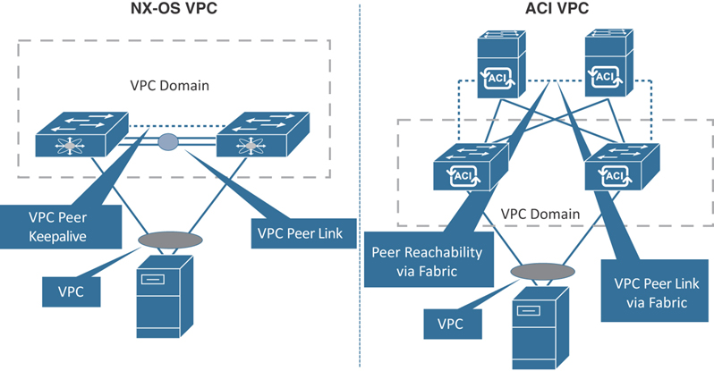
Figure 5-4 VPC in NX-OS and ACI
When creating a VPC domain between two leaf switches, both switches must be in the same switch generation in one of the following Nexus 9300 platform product lines:
Generation 1: Cisco Nexus 9000 switches without EX or FX at the end of the switch model name, such as 9372PX, 93120TX, or 9332PQ
Generation 2: Cisco Nexus 9000 switches with EX or FX at the end of the switch model name, such as 93180YC-EX, 93180YC-FX, 93108TC-EX, or 93108TC-FX
If you try to configure a VPC domain between two switches of different generations, a fault will be raised on the APIC, and the VPC configuration will not be pushed.
Configuring VPC
Configuring VPC requires a few simple steps that can be scripted and automated programmatically for rapid deployment of application infrastructure:
Step 1. Define the VPC domain.
Step 2. Create the interface policy:
Create the interface policy, including LLDP, CDP, LACP, link speed/duplex, and so on.
Create the VPC policy group, including consuming interface policies and associating an AAEP.
Create the interface profile, including choosing the downlink ports and associating the VPC policy group.
Step 3. Create the switch profile:
Associate the interface profile.
Figure 5-5 provides a flow diagram that illustrates this process.
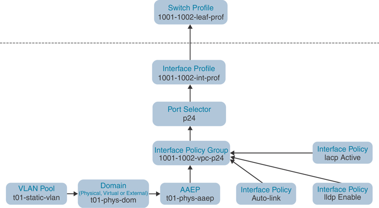
Figure 5-5 VPC Logical Flow Diagram
Note
Following a naming standard is important in the ACI policy model. Best practice is to use simple and meaningful object names.
Defining the VPC Domain
To define a VPC domain, follow these steps (in ACI Release 3.2.5 and later):
Step 1. Go to Fabric > Access Policies > Policies > Switch > Virtual Port Channel default.
Step 2. Click the + sign to define VPC explicit protection group. The screen shown in Figure 5-6 appears.

Figure 5-6 Defining the VPC Domain
Step 3. Name the VPC explicit protection group (for example, 1001-1002-vpc-grp).
Step 4. Define the VPC logical pair ID. The value has to be between 1 and 1000.
Step 5. Select the two switches you want to group—in this case, 1001 for Switch 1 and 1002 for Switch 2.
Step 6. Click Submit.
As you can see in Figure 5-7, the VPC explicit protection group name you entered is shown (1001-1002-vpc-grp), as is the logical pair ID you entered (1) for the first vpc domain. The virtual IP address (10.34.20.67/32) is an auto-generated IP address from the system TEP pool that represents the virtual shared (anycast) TEP of the VPC switch pair leafs 1001 and 1002; in this case, packets destined to VPC-connected endpoints off Leafs 1001 and 1002 will use this anycast VTEP to send the packets. When it comes to creating VPC domains, ACI is an immense improvement over traditional NX-OS, as there is no need to manually configure the peer link and peer keepalive.
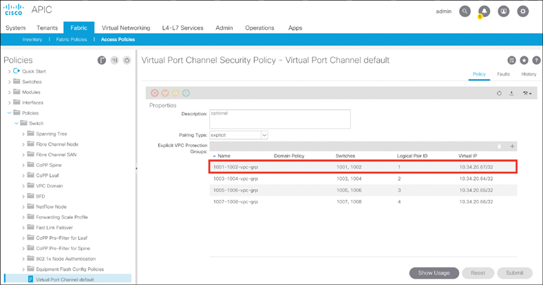
Figure 5-7 VPC Domain Between a Leaf Pair
Creating an Interface Policy
To create an interface policy, follow these steps (in ACI Release 3.2.5 and later):
Step 1. Create the interface policy, such as link-level, CDP, LLDP, or LACP, per your interface use case by going to Fabric > Access Policies > Policies > Interface in the APIC GUI.
Step 2. Create the interface policy group by going to Fabric > Access Policies > Interfaces > Leaf Interfaces > Policy Groups > VPC Interface in the APIC GUI. The screen shown in Figure 5-8 appears.
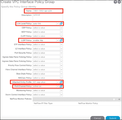
Figure 5-8 Creating a VPC Interface Policy Group
Step 3. Name the VPC interface policy group (for example, 1001-1002-vpc-p24). Choose the appropriate interface policies and associate the AAEP. Click Submit.
Step 4. Create the leaf interface profile by going to Fabric > Access Policies > Interfaces > Leaf Interfaces > Profiles in the APIC GUI, as shown in Figure 5-9.
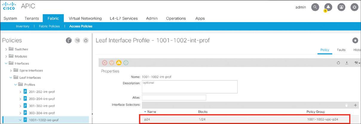
Figure 5-9 Creating a Leaf Interface Profile
Step 5. Name the leaf interface profile (for example, 1001-1002-int-prof).
Step 6. Click the + sign to choose the interface selector.
Step 7. Name the access port selector (for example, p24).
Step 8. Select the interface ID 1/24.
Step 9. Associate to the interface policy group 1001-1002-vpc-p24 and click OK.
Step 10. Click Submit to finish creating the leaf interface profile.
Creating a Switch Profile
To create a switch profile, follow these steps (in ACI Release 3.2.5 and later):
Step 1. Create the switch profile by going to Fabric > Access Policies > Switches > Leaf Switches > Profiles in the APIC GUI (see Figure 5-10).

Figure 5-10 Creating a Switch Profile
Step 2. Name the leaf profile (for example, 1001-1002-leaf-prof).
Step 3. Choose leaf selectors by clicking the + sign.
Step 4. Name the leaf selectors (for example, L1001-1002).
Step 5. Choose leaf switches 1001 and 1002, click Update, and click Next.
Step 6. Choose the leaf interface profile (in this example, 1001-1002-int-prof).
Step 7. Click Finish.
Port Channel
A port channel allows multiple physical links bundled together with a single ACI leaf to appear as a single logical port for link redundancy and extra bandwidth (see Figure 5-11). Port channel configuration can use the active/passive LACP or the Static Channel mode.

Figure 5-11 Port Channel in ACI
Configuring a Port Channel
Configuring a port channel is quite similar to configuring a virtual port channel aside from a few minor differences shown in the following steps. Again, as with VPC configuration, these steps can all be scripted and automated programmatically for rapid deployment of application infrastructure:
Step 1. Define the VPC domain. (There is no need to create a VPC domain because this is just a single-chassis port channel.)
Step 2. Create the interface policy:
Create the interface policy, including LLDP, CDP, LACP, link speed/duplex, and so on.
Create the PC policy group, including consuming interface policies and associating an AAEP.
Create the interface profile by choosing downlink ports and associating a PC policy group.
Step 3. Create the switch profile.
Associate the interface profile.
Figure 5-12 provides a flow diagram that illustrates this process.

Figure 5-12 Port Channel Logical Flow Diagram
Note
Following a naming standard is important in the ACI policy model. Best practice is to use simple and meaningful object names.
Creating an Interface Policy
To create an interface policy, follow these steps (in ACI Release 3.2.5 and later):
Step 1. Create the interface policy, such as link-level, CDP, LLDP, or LACP, per your interface use case by going to Fabric > Access Policies > Policies > Interface in the APIC GUI (see Figure 5-13).

Figure 5-13 Creating a PC Interface Policy Group
Step 2. Create the interface policy group by going to Fabric > Access Policies > Interfaces > Leaf Interfaces > Policy Groups > PC Interface in the APIC GUI.
Step 3. Name the PC interface policy group (for example, 1003-pc-p15_16).
Step 4. Choose the appropriate interface policies and associate the AAEP. Click Submit.
Step 5. Create a leaf interface profile by going to Fabric > Access Policies > Interfaces > Leaf Interfaces > Profiles in the APIC GUI (see Figure 5-14).

Figure 5-14 Creating the Leaf Interface Profile
Step 6. Name the leaf interface profile (for example, 1003-int-prof).
Step 7. Click the + sign to choose the interface selector.
Step 8. Name the access port selector (for example, p15_16).
Step 9. Select the interface IDs 1/15 and 1/16.
Step 10. Associate to the interface policy group 1003-pc-p15_16 and click OK.
Step 11. Click Submit to finish creating the leaf interface profile.
Creating a Switch Profile
To create a switch profile, follow these steps (in ACI Release 3.2.5 and later):
Step 1. Create the switch profile by going to Fabric > Access Policies > Switches > Leaf Switches > Profiles in the APIC GUI (see Figure 5-15).

Figure 5-15 Creating a Switch Profile
Step 2. Name the leaf profile (for example, 1003-leaf-prof).
Step 3. Choose leaf selectors by clicking the + sign.
Step 4. Name the leaf selectors (for example, L1003).
Step 2. Choose leaf switch 1003, click Update, and click Next.
Step 5. Choose the leaf interface profile (in this example, 1003-int-prof).
Step 6. Click Finish.
Access Port
Access ports are the end host–facing ports such as server, IP storage, switch, router, and L4/L7 devices. In ACI, access ports can be defined as Trunk, Access (802.1P), or Access (untagged). Why are there two types of access port configurations in ACI, and what is the difference between them?
IEEE 802.1P refers to a QoS implementation using 802.1Q protocols, which basically means that the switch access port with an 802.1P setting should send and receive frames tagged with VLAN 0, whereas the switch access port with an Untagged setting should send and receive frames without any VLAN tag. Most modern operating systems should be able to manage frames tagged with VLAN 0 similar to Untagged frames. However, installing a server operating system using a Preboot Execution Environment (PXE) method across a Cisco ACI fabric switching infrastructure could lead to some issues because small BIOS/firmware cannot read VLAN 0 tagged frames.
ACI second-generation—and later—switches (EX/FX) do not distinguish between the Access (802.1p) and Access (Untagged) modes. When EPGs are deployed on second-generation switch ports configured with either 802.1p or Untagged mode, the traffic always egresses untagged. The port accepts ingress traffic that is untagged, tagged, or in 802.1p mode. Figure 5-16 illustrates this.
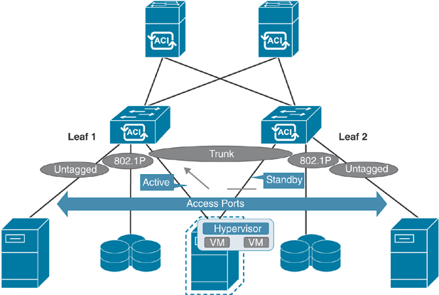
Figure 5-16 Access Ports in ACI
Configuring an Access Port
Except for some minor differences, configuration of access ports involves the same policy-driven workflow as configuration of VPCs or port channels, as shown in the following steps:
Step 1. Create the interface policy:
Create the interface policy, including LLDP, CDP, LACP, link speed/duplex, and so on.
Create the access port policy group, including consuming interface policies and associating AAEP.
Create the interface profile, including choosing downlink ports and associating the PC policy group.
Step 2. Create the switch profile:
Associate the interface profile.
Again, as with configuration of VPCs and single port channels, these steps can all be scripted and automated programmatically for rapid deployment of application infrastructure.
You can either go with a single physical link to a single leaf or dual physical links (active/standby) to two top of the rack (ToR) leafs. Note that in both cases, just one access port policy group (in this example, t01-access-polgrp) is reused multiple times. Figures 5-17 and 5-18 are flow diagrams that illustrate the process.

Figure 5-17 Access Port Logical Flow Diagram (Single Link to Single Leaf)

Figure 5-18 Access Port Logical Flow Diagram (Dual Links to Two Leafs)
Note
Following a naming standard is important in the ACI policy model. Best practice is to use simple and meaningful object names.
Creating an Interface Policy
To create an interface policy, follow these steps (in ACI Release 3.2.5 and later):
Step 1. Create an interface policy, such as link-level, CDP, LLDP, or LACP, per your interface use case, by going to Fabric > Access Policies > Policies > Interface in the APIC GUI.
Step 2. Create an interface policy group by going to Fabric > Access Policies > Interfaces > Leaf Interfaces > Policy Groups > Leaf Access Port in the APIC GUI.
Step 3. Name the leaf access port policy group (for example, t01-access-polgrp).
Step 4. Choose the appropriate interface policies and associate the AAEP, as shown in Figure 5-19, and click Submit.
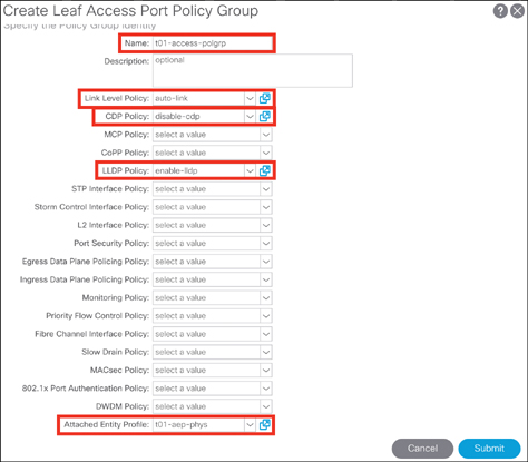
Figure 5-19 Creating an Access Port Interface Policy Group
Step 5. Create a leaf interface profile by going to Fabric > Access Policies > Interfaces > Leaf Interfaces > Profiles in the APIC GUI, as shown in Figure 5-20.

Figure 5-20 Creating a Leaf Interface Profile
Step 6. Name the leaf interface profile (for example, 1004-int-prof).
Step 7. Click the + sign to choose the interface selector.
Step 8. Name the access port selector (for example, p15).
Step 9. Select the interface ID 1/15.
Step 10. Associate with the interface policy group t01-access-polgrp and click OK.
Step 11. Click Submit to finish creating the leaf interface profile.
Creating a Switch Profile
To create a switch profile, follow these steps (in ACI Release 3.2.5 and later):
Step 1. Create a switch profile by going to Fabric > Access Policies > Switches > Leaf Switches > Profiles in the APIC GUI, as shown in Figure 5-21.
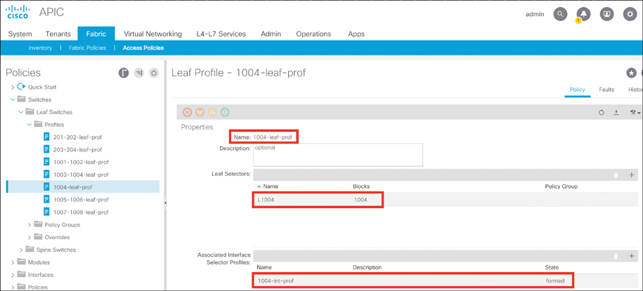
Figure 5-21 Creating a Switch Profile
Step 2. Name the leaf profile (for example, 1004-leaf-prof).
Step 3. Choose leaf selectors by clicking the + sign.
Step 4. Name the leaf selectors (for example, L1004). Choose leaf switch 1003, click Update, and click Next.
Step 5. Choose the leaf interface profile (in this example, 1004-int-prof).
Step 6. Click Finish.
Best Practices in Configuring Access Policies
Cisco has established several best practices for ACI fabric configuration based on field experiences and lab scale-out testing. These are not configuration-related requirements and might be different for different cases and for different customers, but following these best practices can help simplify Day 2 operations of the Cisco ACI fabric.
Policy Best Practices
Best practice is to reuse policies whenever possible for manageability and efficient usage. For example, there should be policies for 1/10/40/100 Gbps and auto port speeds, CDP, LLDP, LACP, and so on.
Following a naming standard is important in the ACI policy model. When naming policies, use names that clearly describe the configuration setting. For example, a policy that enables LACP in active mode could be called something like LACP-Active. There are many default out-of-the-box policies, but it is hard to remember all the default values, so policies need to be clearly named to avoid mistakes when making configuration changes in the fabric.
Create a switch profile individually for each leaf switch, and additionally create a separate switch profile for each VPC pair if VPC is configured.
Domain Best Practices
Create one physical domain per tenant for bare-metal servers that requires similar treatment, excluding the virtualized compute part of VMM integration with ACI.
Create one physical domain per tenant for external network connectivity.
If a VMM domain needs to be leveraged across multiple tenants, a single VMM domain can be created and associated with all leaf ports where virtualized compute is connected.
AAEP Best Practices
When possible, create one AAEP for physical bare-metal compute and another AAEP for virtualized compute. If a single interface needs access to both virtual and physical domains, multiple domains can be associated with a single AAEP. A good use case for this, as described earlier, would be if you had a blade switch connected to the ACI fabric. On a given leaf switch port, there might be several hosts connected, offering different functions and trunking different VLAN ranges. In such a case, the AAEP associated with the interfaces connecting to the blade switch would need access to multiple domains.
Compute and Storage Connectivity
Compute connectivity is key for all application workloads to function properly on the Cisco ACI fabric. Therefore, fabric connectivity requirements that are dictated by the server infrastructure team must be carefully considered. Different customers have different varieties of compute platforms. Platforms include blade systems such as Cisco UCS B-Series and standalone pizza boxes such as Cisco UCS C-Series servers as well as third-party blade system and standalone servers that all need to be connected to the ACI fabric. These compute platforms, whether they are baremetal or virtualized, can be connected to the ACI fabric using VPC, regular port channel, or access port configuration. These policies are all controlled by access policies in the Cisco APIC. The connection to a bare-metal compute platform can also be established via Cisco Fabric Extender (FEX). Let’s look at FEX connectivity with ACI leafs and some of the limitations.
FEX Connectivity
FEX provides an alternative way to connect end host devices to the ACI fabric. However, there are restrictions to be aware of when using FEX connected to ACI leafs:
There is no support for external router connectivity using L3Outs on FEX ports.
FEX is supported in only a single home because FEX connects to one leaf only.
There is no FCoE support on FEX ports except for N9K-C93180YC-FX and N9K-C93108TC-FX leaf switches running ACI Release 2.3(x) and later.
802.1P CoS values are not preserved when the outgoing interface is on the FEX port.
With ACI Release 3.1(x) or later, multicast sources or receivers connected to FEX ports are supported.
With ACI Release 3.2(x) or later, FEX is supported for connecting remote leafs.
Always check the Cisco website for the latest limitations related to feature such as FEX connectivity in the ACI software release notes. The ACI fabric supports FEX server-side VPCs, also known as FEX straight-through VPCs. In this configuration, as illustrated in Figure 5-22, FEX uplinks to leaf downlinks connect via regular port channel to a single leaf switch.
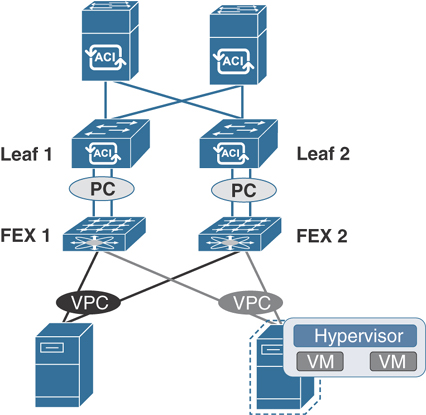
Figure 5-22 ACI Topology Supporting FEX
Cisco Blade Chassis Servers UCS B-Series
In order to connect a UCS B-Series blade chassis to ACI fabric, the type of Layer 2 connection needed on the fabric interconnect–facing ports must be determined first. You must ensure that VLANs that are required on UCS blades are trunked to uplink ports of fabric interconnects connecting to ACI leafs. You also need to make sure the link discovery protocol—either CDP or LLDP—is configured the same way on both UCS fabric interconnects and ACI leafs. A best practice is to leverage a VPC to connect the UCS fabric interconnects to create a MEC. In this scenario, individual link and fabric switch failures are mitigated to maintain a higher expected service uptime, as illustrated in Figure 5-23.

Figure 5-23 Connecting a Blade Chassis Server to an ACI Leaf
Standalone Rack-Mount Servers
Like blade systems, standalone rack-mount servers such as UCS C-Series can be connected to ACI leafs in the same three connection scenarios: VPC, regular port channel, and access port. For redundancy and better convergence during failures, VPC connection is highly recommended unless the compute platform does not support LAG or Ethernet bonding techniques such as in the case of VMWare vSphere 6.0 and earlier releases. When a server is being connected to the ACI fabric, the kind of traffic expected out of the server links needs to be considered for proper bandwidth determination. Standalone server connectivity can also be done via FEX port. Figure 5-24 shows the options for connecting servers directly to ACI leafs or through FEX.
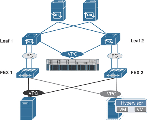
Figure 5-24 Connecting a Bare-Metal Server to an ACI Leaf
Connecting Storage in ACI
Cisco ACI provides storage connectivity using FCoE on a cloud-scale EX/FX platform. FCoE is a protocol that enables you to send Fibre Channel traffic over an Ethernet medium. This is useful for sending Fibre Channel traffic over high-speed Ethernet transport while preserving the Fibre Channel packets. The other benefit of using FCoE is to use a converged infrastructure for both Fibre Channel and Ethernet traffic.
With FCoE support in ACI, the hosts are connected through virtual fiber (F) ports deployed on an ACI leaf switch. The SAN storage switch and Fibre Channel network are connected through a Fibre Channel forwarding (FCF) bridge to the ACI fabric through a virtual network port (NP) deployed on the same ACI leaf switch where the host is connected as a virtual F port. The reason for this limitation is that the ACI leaf switch does not perform local switching between SAN accessing hosts, and the FCoE traffic is not forwarded to a spine switch. In Fibre Channel technology, virtual NP and virtual F ports are referred to as virtual Fibre Channel (VFC) ports. Figure 5-25 illustrates FCoE storage connectivity with ACI leafs.
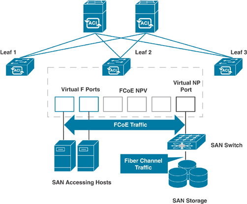
Figure 5-25 ACI Topology Supporting FCoE
FCoE traffic requires you to configure a separate VLAN connectivity over which SAN-accessing hosts broadcast FCoE Initialization Protocol (FIP) packets to discover the interfaces enabled as F ports. ACI allows one VSAN assignment per bridge domain. You must configure VSAN and VLAN pool allocations as static while configuring FCoE. (Only static allocation is allowed in VSAN configuration.) While configuring VFC interfaces in ACI, F port mode is the default mode on the interface. Therefore, you need to specifically configure NP port mode in access policies.
L4/L7 Service Device Connectivity
L4/L7 services are a critical component of application hosting infrastructure for all data center networks. Therefore, it is important to understand physical connectivity options for L4/L7 devices in ACI. Let’s look at a few examples of firewall and load balancer connectivity with ACI.
Connecting Firewalls
Firewalls protect network segments from unauthorized access by users or miscreants while also enforcing security policies and posture. When discussing the networks connected to a firewall, the outside network is typically defined as being in front of the firewall (an unsecured area), while the inside network is protected (by default) and resides behind the firewall; a demilitarized zone (DMZ) allows limited access to outside (external) and inside (internal) users.
While ACI allows any vendor security platform to be connected to the fabric, the focus in this book is the Cisco product line. Cisco firewalls can be connected to a network in either Transparent mode (also called Bridge mode) or Routed mode. Firewalls can be deployed in Failover mode or Cluster mode for redundancy and high availability.
In active/standby failover mode, the heartbeat cable must be connected directly between the firewall pair (recommended) or via ACI leafs using a separate VPC if the two firewalls are not in the same rack. If you are establishing the failover heartbeat connections via ACI leafs, you need to create a private BD (with no subnet) and associate it with an EPG that you need to then statically bind to ACI leaf ports (in this example, the H-Beat VPC ports). Figure 5-26 illustrates the firewall connectivity with ACI leafs in active/standby mode.
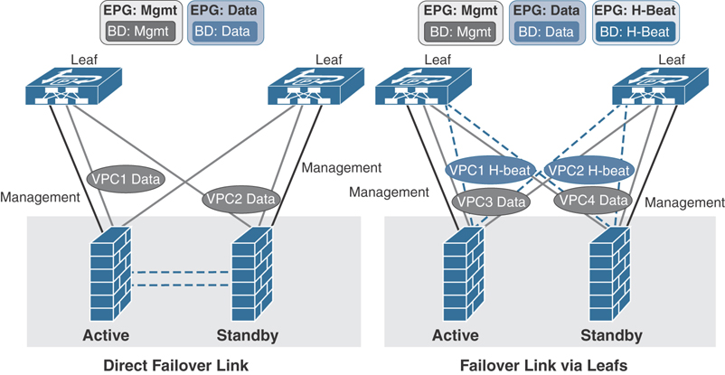
Figure 5-26 ACI Connectivity with a Firewall in Active/Standby Failover Mode
In Cisco Firewall Cluster mode for a two-node cluster, you need to have two separate VPCs for the cluster control link (CCL) as Access (untagged) ports connecting each of the firewall. You also need another separate VPC connecting both firewalls for data that you can Trunk and create Dot1q interfaces for your inside and outside interfaces on firewall cluster. On ACI leafs for firewall CCL traffic, you need to create a BD (with flooding, disable unicast routing and no subnet) and associate it with an EPG that you need to then statically bind to ACI leaf ports (in this example, the CCL VPC ports). Figure 5-27 illustrates firewall cluster connectivity with ACI leafs.
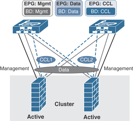
Figure 5-27 ACI Connectivity with a Firewall in Cluster Mode
Connecting Load Balancers
Load balancers provide high availability of applications by seamlessly balancing the load between a pool of servers. They also provide the capability of persisting the user connections to maintain the state of an application. Load balancers can be connected to networks in either Bridge mode or Routed mode to provide transparent inspection or router-like functionality. When operating in routed mode, the recommendation is to connect any router-like port to an external routed network in ACI rather than use an EPG/BD combination.
Like firewalls, load balancers can also be deployed in failover active/standby mode for redundancy and high availability. Most vendors of load balancers recommend using dedicated links—and preferably a separate VPC for heartbeat connection—when connecting to ACI. However, you can use a single VPC to traverse both data and heartbeat traffic by segmenting each function in a different VLAN and bridge domain, as shown in Figure 5-28.
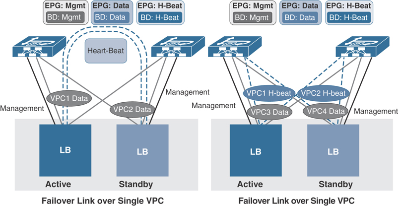
Figure 5-28 ACI Connectivity with Load Balancers
Network Connectivity
ACI has brought some new methodologies and terms to network connectivity. ACI uses traditional Layer 2 and Layer 3 constructs, but traffic forwarding requires additional steps, such as proper contracts between EPGs and physical connectivity on the interface level that is mapped to the logical construct under tenant configuration. In this section you will learn about various network connectivity options in ACI.
Connecting an External Bridge Network
Enterprises often need to extend their application network infrastructure between multiple data centers. Sometimes perhaps during the migration phase, they need to connect legacy network infrastructure to ACI in order to seamlessly move their workloads. Certain applications requires Layer 2 connectivity between application hosting facilities. This can be accomplished in Cisco ACI in two ways:
Extending EPGs outside the ACI fabric
Extending an ACI bridge domain outside the fabric
Extending EPGs Outside the ACI Fabric
The simplest way to extend Layer 2 connectivity to hosts residing outside ACI fabric is to extend an EPG outside the ACI fabric by statically assigning a leaf port and VLAN to an existing EPG. After doing so, all the traffic received on this leaf port with the configured VLAN is mapped to the EPG, and the configured policy for this EPG is enforced. This is a typical network-centric migration strategy, where a one-to-one mapping between legacy VLAN and EPG is desired. The endpoints do not need to be directly connected to the ACI leaf, as the traffic classification is based on the VLAN encapsulation received on a port, as shown in Figure 5-29.

Figure 5-29 Extending an EPG Outside the ACI Fabric
To statically assign a Layer 2 connection on an ACI leaf port to an EPG, follow these steps:
Step 1. From the top main menu bar, choose Tenants > ALL TENANTS.
Step 2. In the navigation pane, select the user-defined tenant in which you want to extend EPG outside the ACI fabric.
Step 3. In the navigation pane, go to Application Profiles > App_Profile_Name > Application EPGs > EPG_Name > Static Bindings (Paths).
Step 4. In the work pane, choose Action > Deploy Static EPG on PC, vPC or Interface.
In the Path field, specify a port as well as a VLAN ID.
Click one of the Deployment Immediacy radio buttons. Deployment immediacy determines when the actual configuration will be applied on the leaf switch hardware. The immediacy also determines when the hardware resource, such as a VLAN resource and policy content-addressable memory (CAM) to support the related contract for this EPG, will be consumed on the leaf switch. The option Immediate means that the EPG configuration and its related policy configuration will be programmed in the hardware right away. The option On Demand instructs the leaf switch to program the EPG and its related policy in the hardware only when traffic matching this policy is received for this EPG.
Click one of the Mode radio buttons to specify whether the ACI leaf expects incoming traffic to be tagged with a VLAN ID or not:
Trunk: The Trunk option means that the leaf node expects incoming traffic to be tagged with the specified VLAN ID previously established. This is the default deployment mode. Choose this mode if the traffic from the host is tagged with a VLAN ID. Multiple EPGs can be statically bound to the same interface as long as the encapsulation VLAN/VXLAN ID is unique. This is similar to the switchport trunk allowed vlan vlan_ID command.
Untagged: The Untagged option means that the leaf expects untagged traffic without a VLAN ID. Much as with the switchport access vlan vlan_ID command, with this option you can assign the interface to only one EPG. This option can be used to connect a leaf port to a bare-metal server whose network interface cards (NICs) typically generate untagged traffic. A port can have only one EPG statically bound to a port as untagged.
802.1P: The 802.1P option refers to traffic tagged with 802.1P headers. 802.1P mode is useful when it’s necessary to handle the traffic on one EPG as untagged to the interface (much as with the switchport trunk native vlan vlan_ID command), but, unlike the untagged mode, 802.1P allows other tagged EPGs to be statically bound to the same interface.
Figure 5-30 illustrates these steps in the APIC GUI.

Figure 5-30 Extending an EPG Outside in the APIC GUI
In addition to completing the preceding configuration, the VLAN you are trying to deploy must be provided from a VLAN pool. This means that the domain that provides access to that pool must also be associated on the EPG. The domain can be associated by navigating to EPG > Domains > Add Physical Domain Association, as illustrated via Figure 5-31.
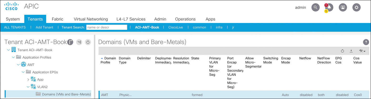
Figure 5-31 Attaching a Domain to an EPG
Extending an ACI Bridge Domain Outside the Fabric
An external bridge domain, also known as Layer 2 outside, helps you extend an entire bridge domain and not just an individual EPG under the bridge domain to the outside network, as illustrated in the earlier section “Extending EPGs Outside the ACI Fabric.”
In ACI, Layer 2 extension can also be accomplished by creating an external bridge domain as an extension of the bridge domain to the outside network; a Layer 2 outside connection must be created for the bridge domain. During this process, create a new external EPG to classify this external traffic. This new EPG will be part of the existing bridge domain. Classify any outside connections or endpoints into this new external EPG. With two separate EPGs, you also need to select which traffic you would like to traverse the two EPGs. Much like the previous example of adding an endpoint to a preexisting EPG, this method also allows the endpoints to share the same subnet and default gateway. Figure 5-32 illustrates the extension of an ACI bridge domain outside the fabric.

Figure 5-32 Extending a Bridge Network Outside the ACI Fabric
To create an external Layer 2 domain, follow these steps:
Step 1. From the main menu bar, choose Tenants > ALL TENANTS.
Step 2. In the navigation pane, select the user-defined tenant in which you want to configure external routed networks.
Step 3. Browse through the menu tabs on the left side of the navigation pane and go to Networking > External Bridged Networks.
Step 4. Right-click External Bridged Networks and choose Create Bridged Outside.
Step 5. In the Create Bridged Outside dialog box, perform the following actions:
Associate the bridge outside connection with the bridge domain and a VLAN. This VLAN must be configured on the external Layer 2 network. The bridge outside connection will put this VLAN and the bridge domain of the ACI fabric under the same Layer 2 domain. The VLAN must be part of the VLAN pool that is associated with the external bridge domain configuration.
From the External Bridged Domain drop-down list, create a Layer 2 domain if one does not already exist.
While creating the Layer 2 domain, if it does not already exist, create a VLAN pool to associate to the VLAN on the bridge outside connection. This is a way to specify the range of the VLAN IDs that will be used for creating a bridge outside connection, and it helps avoid overlap in the VLAN range between VLANs used for an EPG and those in use for a bridge outside connection.
Add a Layer 2 border leaf node and Layer 2 interface for a bridge outside connection.
Click Next and provide a name for the Layer 2 external EPG. All of the traffic entering the ACI fabric with the designated VLAN (the VLAN ID provided earlier) will be classified into this Layer 2 EPG.
Configure a contract to allow communication between the existing endpoints in the existing EPG and the new external Layer 2 EPG. In the navigation pane, choose External Bridged Networks > Networks and specify a contract to govern this policy as the consumed contract. The communication between this external Layer 2 EPG and your existing internal EPG will then be allowed.
Create an AAEP, which is a policy object that tells the APIC to allow certain encapsulation VLANs on selected ports.
After finishing the final step, you should have the desired reachability between the inside and outside Layer 2 segments. Figure 5-33 shows the configuration screen for extending an ACI bridge domain outside the fabric.

Figure 5-33 Extending an ACI Bridge Domain Outside the ACI Fabric
Connecting an External Routed Network
The most important consumer of any application is the end user, which generally does not directly attach to the fabric. Therefore, there must be connectivity to the external network from ACI fabric hosting applications. A company must be able to connect to both its internal corporate backbone network and to the Internet to provide access to the applications. This integration is possible with Cisco ACI at the tenant policy level. Layer 3 connectivity to a device such as a router is known in ACI as an external routed network or L3Out. The external routed network provides IP connectivity between tenant-associated networks and the external IP network. Each Layer 3 external connection is associated with one tenant network. The Layer 3 external network is only needed when a group of devices in the application profile require Layer 3 connectivity to a network outside the ACI fabric.
An application profile enables an operator to group different tiers of an application into EPGs. These application tiers might have requirements for external connectivity into them. Figure 5-34 shows a logical layout demonstrating this communication.
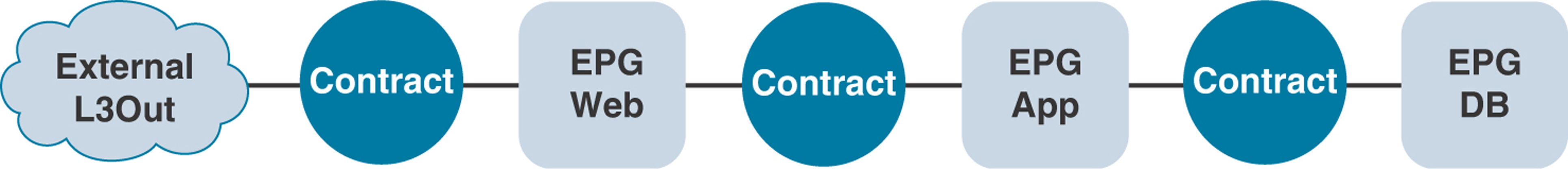
Figure 5-34 Three-Tier Application with External Network Connectivity
For example, web servers need a connection to the outside world for end-user consumption. With ACI, the communication is defined by a contract because of its whitelist model to a configured external Layer 3 endpoint group. As the operator of the fabric, you can provide the tenant administrator with the ability to interface to an external Layer 3 connection in various ways by using a uniquely defined Layer 3 outside configuration for the tenant application profile or via a shared common infrastructure.
External Layer 3 connections are usually established on leafs that are commonly known as border leafs in ACI. Any ACI leaf can become a border leaf, provided that it has an external routed network configured. In large-scale ACI designs, it might be efficient to have dedicated ACI leafs as border leafs to perform Layer 3 lookups and routing. It is not necessary to call border leafs when you only connect them to a physical external router. Other devices, such as servers performing routing functionality, can still connect to the border leafs, as in the case of Kubernetes nodes running on a RedHat Linux platform and peering to ACI border leafs via BGP. In the ACI fabric, the external Layer 3 connection can be one of the following types:
Physical Layer 3 interface
Subinterface with 8021.Q tagging
Switch virtual interface (SVI)
Figure 5-35 depicts the logic of public and private networks.

Figure 5-35 Three-Tier Application with External Users Consuming Internal/External Applications
With devices connecting through the external Layer 3 connection, the external network has learned of the internal ACI network 10.10.10.0/24, as it is advertised to the adjacent router through the Layer 3 external connection, as depicted in Figure 5-35. For the private networks, ACI does not advertise the networks through the routing protocol to the adjacent Layer 3 router, and the networks are not reachable to devices external to the fabric.
In older versions of ACI, routes learned externally from the fabric are not advertised through other ports. This behavior creates a non-transit fabric. In Release 1.1 and later, ACI is able to act as a transit network, and routes learned from one external Layer 3 connection can be advertised out to a different external Layer 3 connection—and not just to fabric internal prefixes.
The network team provides the external Layer 3 connectivity for the tenants. One common mechanism is to use subinterfaces on a router to create different Layer 3 domains since each tenant will likely not have its own external router for cost reasons.
External Layer 3–Supported Routing Protocols
The following routing options are supported for external Layer 3 network connectivity in ACI:
Static routes: In ACI, you can define static routes to reach the external networks. Using static routes reduces the size and complexity of the routing tables in the leaf node(s) but increases administrator overhead. With static routes, you must also configure the static path back to the internal ACI network that you want to be reachable from the outside world.
OSPF: Open Shortest Path First (OSPF) is a commonly used Interior Gateway Protocol in the industry today, and ACI has supported it since its first release. You can define OSPF area types such as regular, NSSA, and stub in ACI. Using a not-so-stubby area (NSSA) reduces the size of the OSPF database and the need to maintain the overhead of routing protocols with large route table sizes. With OSPF NSSA, the router learns only a summarization of routes, including a default path out of the fabric. OSPF NSSA advertises to the adjacent router the internal ACI public subnets part of the Layer 3 external. You enable OSPF by configuring an ospfExtP policy managed object under an l3extOut policy managed object.
EIGRP: Enhanced Interior Gateway Routing Protocol (EIGRP) is similar to other routing protocols in the ACI fabric and supports features such as IPv4 and IPv6 routing, virtual routing and forwarding (VRF) and interface controls for each address family, redistribution with OSPF across nodes, a default route leak policy per VRF instance, passive interface and split horizon support, route map control for setting tags for exported routes, and bandwidth and delay configuration options via EIGRP interface policy. At this writing, only a few EIGRP features are not supported in ACI; among them are stub routing, EIGRP used for BGP connectivity, summary prefix, and per-interface distribution lists for imports and exports.
BGP: ACI fabric supports Border Gateway Protocol (BGP) peering with external routers. BGP peers are associated with an l3extOut policy managed object. Multiple BGP peers can be configured per single l3extOut policy managed object. BGP can be enabled at the l3extOut level by defining the bgpExtP managed object under an l3extOut policy managed object. BGP peer reachability can occur through OSPF, EIGRP, a connected interface, static routes, or a loopback. Internal BGP (iBGP) or external BGP (eBGP) can be used for peering with external routers. The BGP route attributes from the external router are preserved because Multiprotocol Border Gateway Protocol (MP-BGP) is used for distributing the external routes in the fabric. BGP enables IPv4 and/or IPv6 address families for the VRF associated with an l3extOut policy managed object. With iBGP, ACI supports only one autonomous system (AS) number, which has to match the one that is used for the internal MP-BGP route reflector. Without MP-BGP, the external routes (static, OSPF, or BGP) for the Layer 3 outside connections are not propagated within the ACI fabric. Given that the same AS number is used for both cases, the user must learn the AS number on the router to which the ACI border leaf will connect and use that AS number as the BGP AS number when using the ACI internal fabric.
Configuring MP-BGP Spine Route Reflectors
ACI uses MP-BGP to distribute external network prefixes inside the fabric. This requires a full mesh of iBGP peering between all leafs and spines fabric-wide or use of a more efficient way of configuring route reflectors on spine switches to avoid excessive route peering. To enable BGP route reflectors in the ACI fabric, the fabric administrator must select at least two spine switches (for redundancy) to act as a route reflector by assigning a BGP AS number for the fabric. After the BGP route reflectors are configured, it is possible to advertise external routes in the fabric.
To configure a BGP route reflector policy, you need to follow these steps:
Step 1. From the top menu bar, choose System > System Settings > BGP Route Reflector.
Step 2. On the right side of the work pane, perform the following actions:
Input the AS number of your choice. This is locally significant within the ACI fabric.
Add the two spine switch nodes that will be members of this BGP route reflector policy.
Click Submit.
Step 3. From the top menu bar, choose Fabric > Fabric Policies > Pods > Policy Groups.
Step 4. On the right side of the work pane, choose Actions > Create Pod Policy Group.
Step 5. In the Create Pod Policy Group dialog box, from the BGP Route Reflector Policy drop-down list, choose Default. Click Submit.
Step 6. From the top menu bar, choose Fabric > Fabric Policies > Pods > Profiles.
Step 7. On the right side of the work pane, choose Actions > Create Pod Profile. Choose the default pod profile and associate the previously created pod policy group. Click Submit.
Figure 5-36 shows the screen where these route reflector configuration steps occur.

Figure 5-36 Configuring a BGP Route Reflector
Configuring External Routed Networks
In ACI, you can configure external routed networks on leafs called border leafs that can be reused for multiple tenants. If an external router is a network switch with a Layer 2 trunk interface, the external Layer 3 connection can be configured to route via SVI. Routers capable of using subinterfaces can be used to provide multiple external Layer 3 connections for multiple VRF instances and/or tenants. The fabric administrator can configure multiple external Layer 3 connections by using either a subinterface or SVI provided to each tenant. Layer 3 connectivity can be provided either using the routing protocol of your choice—such as OSPF, EIGRP, or BGP—or static routing.
Before diving into the actual configuration of an external routed network, it’s important that you memorize the procedural steps workflow illustrated in Figure 5-37.

Figure 5-37 Procedural Steps Workflow for Layer 3 Outside
Let’s look at an external routed network (also known as L3Out) configuration through a tenant network with an OSPF NSSA setup. Figure 5-38 shows a sample configuration for a Layer 3 external network into ACI using the OSPF routing protocol.
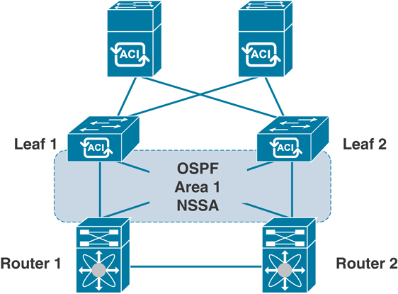
Figure 5-38 L3Out Topology Using OSPF
To integrate Layer 3 through a tenant network with OSPF/NSSA, follow these steps:
Step 1. From the top menu bar, choose Tenants > ALL TENANTS.
Step 2. In the navigation pane, select the user-defined tenant in which you want to configure external routed networks.
Step 3. Browse through the menu tabs on the left side of the navigation pane and go to Networking > External Routed Networks.
Step 4. Right-click External Routed Networks and choose Create Routed Outside.
Step 5. In the Create Routed Outside dialog box, perform the following actions (see Figure 5-39):
In the Name field, enter a name for the external routed networks policy object.
From the VRF drop-down list, choose a VRF option for your tenant.
Click the OSPF checkbox.
In the OSPF Area ID field, enter an OSPF area ID.
In the OSPF Area Control section, ensure that the Send redistributed LSAs into NSSA area and Originate summary LSA checkboxes are selected.
In the OSPF Area Type section, click the NSSA Area radio button.

Figure 5-39 Configuring L3Out Using OSPF
In the Nodes and Interfaces Protocol Profiles section, click + to add a profile.
In the Create Node Profile dialog box, perform the following actions:
In the Name field, enter a name for the node profile policy object.
In the Nodes section, click + to add a node.
In the Select Node dialog box, perform the following actions:
From the Node ID drop-down list, choose a registered leaf node to use as the border leaf.
In the Router ID field, enter the router’s IP address.
Uncheck the Router ID as Loopback Address checkbox if you want to use another IP address as your router’s loopback address.
In the Loopback Addresses section, click + to add a loopback address.
Enter the loopback address of your choice and click Update.
Click OK.
Step 6. In the OSPF Interface Profiles section, click + to create an OSPF interface profile.
Step 7. In the Create Interface Profile dialog box, perform the following actions:
In the Name field, enter a name for the interface profile policy object and click Next.
Choose the authentication type (MD5 authentication, no authentication, or simple authentication). Type the authentication key and confirm it.
From the OSPF Policy drop-down list, choose Create OSPF Interface Policy. When defining the interaction with external adjacent OSPF router, you must specify the policy interaction.
In the Create OSPF Interface Policy dialog box, perform the following actions:
In the Name field, enter a name for the OSPF interface policy of your choice, such as OSPF-Point2Point.
In the Network Type section, click the radio button that matches the external adjacent router, such as Point to Point.
Complete the remainder of the dialog box as appropriate to your setup in terms of OSPF interface cost, controls, and timers settings.
Click Submit.
Step 8. In the Interfaces section, click on the Routed Interfaces tab. You can also select SVI and Routed Subinterface as your choice.
Step 9. Click the + sign to select a routed interface.
Step 10. In the Select Routed Interface dialog box, perform the following actions:
From the Node drop-down list, choose the node leaf router that you want to connect to the external adjacent router.
From the Path drop-down list, choose the interface on the leaf router that you want to connect to external adjacent router interfaces.
In the IP Address field, enter the IP address of the border leaf node from the transport network segment for which you want to establish OSPF peering with the external adjacent router (for example, 100.100.100.1/24).
In the MTU (bytes) field, enter the maximum MTU size that matches your external adjacent router settings. (The default is 9000.)
Complete the remainder of the dialog box as appropriate to your setup and click OK multiple times and then click Next to configure external EPG networks.
Step 11. In the External EPG Networks section, click + to create an external network.
Step 12. From the Create External Network dialog box, in the IP Address field, enter 0.0.0.0/0 to permit the learning of any subnet. Create and apply the appropriate contract and click OK.
Step 13. Click Finish.
Figure 5-40 shows the screens for completing steps 6 through 13.

Figure 5-40 Configuring the L3Out Node Profile, Interface Profile, and External EPG
GOLF
As mentioned earlier, you ensure that traffic flows in and out of the Cisco ACI fabric to the external Layer 3 network domain by creating external routed networks, commonly known as L3Out. These external connections can either be via border leafs, as discussed earlier, or via connectivity through spines called GOLF.
As shown in Figure 5-41, the traditional ACI L3Out approach uses a VRF-Lite configuration to extend connectivity for each VRF instance toward the WAN edge routers. The data plane VXLAN encapsulation used within the Cisco ACI fabric is terminated on the border leaf nodes before the traffic is sent out toward the WAN edge routers.

Figure 5-41 Traditional L3Out Connections
Figure 5-42 shows the EVPN-based L3Out, or GOLF, design option. The GOLF approach was originally introduced to scale up the number of VRF instances to be connected to the external Layer 3 network domain. (Cisco ACI supports 1000 VRF instances with GOLF.)
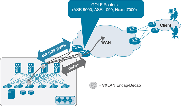
Figure 5-42 GOLF L3Out Connections
As shown in Figure 5-42, with GOLF, the connectivity to the WAN edge routers is not provided by the traditional ACI border leafs; rather, these external routers connect to the spine nodes. The MP-BGP EVPN control plane allows the exchange of routes for all the ACI VRF instances requiring external connectivity, the OpFlex control plane automates the fabric-facing VRF instance configuration on the GOLF router, and the VXLAN data plane enables north–south communication.
Network Connectivity Between Pods and Sites
In ACI, for network connectivity between multiple pods or sites or between the main pod in the data center and a remote site, you need to have an inter-pod network (IPN) connected through spines at each location. This network is also known as an inter-site network, but at the end of the day, it’s just an IP network through which you are extending VXLAN for forwarding traffic with the common policy model. To take care of the overhead of the VXLAN encapsulation, it’s important to increase by at least 50 bytes the supported MTU in the IPN network to allow data plane communication between endpoints at multiple locations. Let’s discuss in more detail various options for this type of network connectivity requirement.
IPN Connectivity Considerations for Multi-Pod and Multi-Site
Numerous connectivity options might surface when you think of how to interconnect the spines deployed in a pod/site to the IPN devices and how the IPN devices deployed in separate pods/sites should be connected together.
You might wonder whether you need to connect all the spines to IPN devices in a pod. It is not a mandatory requirement to connect every spine deployed in a pod/site to the IPN devices. Figure 5-43 shows a scenario in which only two of the four spines are connected to the IPN devices in a multi-pod fabric.
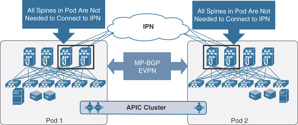
Figure 5-43 Connectivity Between Spines and the IPN
Note
The spines must have EX/FX second-generation line cards in order to peer with IPN devices.
There are not functional implications for unicast communication across sites, as the local leaf nodes encapsulating traffic to a remote pod or site would always prefer the paths via the spines that are actively connected to the IPN devices based on the IS-IS routing metric. At the same time, there are also no implications either for the BUM traffic that needs to be sent to remote pods or sites, as only the spine nodes that are connected to the IPN devices are considered for the designated router position, which is responsible for sending/receiving traffic for a GIPo via IS-IS control plane exchange.
There are a few other potential IPN connectivity considerations. However, none of them are supported due to the reasons spelled out in the section “IPN Connectivity Considerations for Multi-Pod and Multi-Site,” earlier in this chapter. The first option is to connect spines belonging to separate pods or sites with direct back-to-back links, as shown in Figure 5-44.
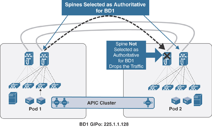
Figure 5-44 Direct Back-to-Back Links Between Spines in Different Pods
As illustrated in Figure 5-44, direct connectivity between spines may lead to potential issues in forwarding BUM traffic across pods/sites in scenarios where the directly connected spines in separate pods/sites have the potential of both not being selected as designated router (DR) for a given bridge domain. Therefore, the recommendation is to always deploy at least one Layer 3 IPN device (or a pair for redundancy) between pods with full-mesh connectivity links.
Figure 5-45 shows another IPN connectivity option, which could point out a similar situation when connecting the spines to the IPN devices.
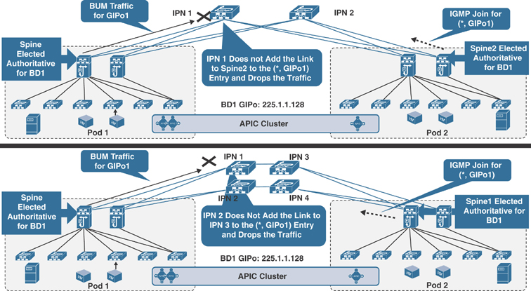
Figure 5-45 Problems Sending BUM Traffic Across Pods
Both of the depicted connectivity scenarios highlight an issue in which the designated spines in Pod 1 and Pod 2 for the bridge domain with GIPo address 225.1.1.128 send the BUM traffic and the IGMP join for that group to two different IPN nodes that do not have a physical path between them. As a consequence, the IPN devices don’t have proper (*, G) state, and the BUM communication fails. To prevent this issue from happening, the recommendation is to always ensure that there is a physical path interconnecting all the IPN devices in a full-mesh connection, as shown in Figure 5-46.

Figure 5-46 Full-Mesh Connectivity to IPN Devices
The full-mesh connections in the scenario between multiple IPN devices could be replaced by a Layer 3 port channel connecting the local IPN devices. This would be useful for reducing the number of required geographic links, as shown in Figure 5-47.

Figure 5-47 Layer 3 Port Channel Connection to IPN Devices
Having full-mesh physical connections between IPN devices, as shown in Figures 5-46 and 5-47, guarantees that each IPN router has a physical path toward the PIM Bidir active RP. There is another challenge you might run into if you have a lower-speed connection between two IPN devices than the speed at which you connect your IPN devices to spines in a pod. In our example of the Layer 3 port channel connecting the two IPN devices, if this is created by bundling 10 Gbps interfaces, the preferred OSPF metric for the path between IPN1 and IPN2 could indeed steer the traffic through one of the spines in Pod 1 because it is connected either via 40 Gbps or 100 Gbps. This issue could be solved by deploying links of consistent speed (10/40/100 Gbps) for connecting local IPN devices to each other and connecting each IPN device to its local spine nodes. Alternatively, it is possible to increase the OSPF cost of the IPN interfaces facing the spines to render that path less preferred from an OSPF metric point of view.
The other consideration is about the link speed support of the connections between the spines and the IPN devices, which depends on the hardware model of the deployed spine node in the ACI fabric. For first-generation spines (for example, modular Nexus 9500 switches with first-generation line cards or Nexus 9336-PQ fixed-chassis spines), only a 40 Gbps interface is supported on the spines, which implies the need to support the same link speed on the IPN devices, as shown in Figure 5-48.

Figure 5-48 Supported Interface Speed Between Spines and IPN Devices
The support of Cisco QSA modules (that convert a QSFP port into a SFP or SFP+ port) on a second-generation spine node (for example, modular Nexus 9500 switches with second-generation EX/FX line cards or Nexus 9364C fixed-chassis spines) allows the use of 10 Gbps link speeds between spines and IPN routers for a specific use case. Please refer to the latest ACI software release notes on the Cisco website to verify support for this connectivity option.
Notice that the links connecting the IPN devices at one location to the IPN devices at the other or, for that matter, to a generic Layer 3 network infrastructure do not need to have 40/100 Gbps link speeds. However, it is not recommended to use connection speeds less than 10 Gbps to avoid traffic congestion across pods/sites that may affect the communication of APIC nodes deployed in separate pods/sites.
Configuring an IPN
In order to configure an IPN, you need to follow the steps outlined in this section, which uses a simple IPN topology for multi-pod to help you understand the configuration steps (see Figure 5-49). However, for production deployment, please follow the detailed configuration guide from the Cisco website.

Figure 5-49 Sample IPN Topology for Configuration
To configure spine connectivity with the IPN router on an APIC, follow these steps:
Step 1. Create a VLAN pool and add VLAN 4. (VLAN 4 is the only VLAN used to peer with IPN devices.)
Step 2. Create an external routed domain. Associate the newly created VLAN pool with this domain.
Step 3. Create an AAEP and associate it with the external routed domain.
Step 4. Create interface and switch policies under the Access Policy tab in the APIC to program ports Eth1/1 on Spine-101 and Spine-102 to peer with IPN devices. Associate the AAEP to the spine interface policy groups.
Step 5. Create an external routed network (L3Out) under the Infra tenant:
Associate the external routed domain.
Select OSPF regular area 0. (The OSPF area could be other than area 0. OSPF is the only protocol supported while peering spines with IPN devices. Any routing protocol or static routes within the IPN are supported.)
Create a routed sub-interface using VLAN 4 as the transport link to route peer with IPN devices using OSPF.
To configure an IPN device in route peering with the ACI spine, use the following steps:
Step 1. Enable the system features on a Nexus device by using the following commands:
feature ospf
feature pim
feature dhcp
feature lldp
!
Step 2. As a recommended (though not required) step, create a VRF instance for IPN traffic:
vrf context IPN
!
Step 3. Set the system and L3 interface MTU to 9150.
system jumbomtu 9216
! On Nexus, System Jumbo MTU size of 9216 is enabled by
default
!
interface Ethernet1/10
 description "Interface connected to Spine"
 no switchport
 mtu 9150
 no shutdown
Step 4. Configure PIM BiDir:
! Dedicated loopback interface for PIM RP
!
interface loopback90
  description "Interface dedicated for PIM RP"
  vrf member IPN
  ip address 90.90.90.1/30
  ip ospf network point-to-point
  ip router ospf 1 area 0.0.0.0
  ip pim sparse-mode
!
! Increasing MTU under PIM
ip pim mtu 9000
vrf context IPN
  ip pim rp-address 90.90.90.2 group-list 225.0.0.0/8 bidir
  ip pim rp-address 90.90.90.2 group-list 239.255.255.240/28
bidir
!
Cisco ACI uses one multicast address per bridge domain to encapsulate BUM traffic to be sent to other TEPs (leaf switches) across the fabric. This concept is extended over the IPN for multi-pod deployments only. IPN for multi-site and remote leaf deployments does not require PIM BiDir. Multicast address 225.0.0.0/8 is the GIPo address range for bridge domains. The 239.255.255.240/28 address is used for fabric-specific purposes, such as ARP gleaning.
Step 5. Enable DHCP Relay on IPN devices for ACI nodes in other pods or sites to get the TEP addresses from the APIC during the initial fabric registration:
service dhcp
ip dhcp relay
!
Step 6. Create a subinterface with Dot1q by using VLAN-4 on IPN devices connecting to the spine:
interface Ethernet1/10.4
  description 40G link to pod1-SPINE-101(Eth1/1)
  mtu 9150
  encapsulation dot1q 4
  vrf member IPN
  ip address 100.100.100.1/30
  ip ospf network point-to-point
  ip ospf mtu-ignore
  ip router ospf 1 area 0.0.0.0
  ip pim sparse-mode
   ! DHCP relay pointing to APIC-1 and APIC2 TEP addresses
  ip dhcp relay address 10.1.0.1
  ip dhcp relay address 10.1.0.2
  no shutdown
!
Step 7. Configure the interface between IPN devices:
interface Ethernet1/50
  description link between IPN devices
  mtu 9150
  vrf member IPN
  ip address 50.50.50.1/30
  ip ospf network point-to-point
  ip ospf mtu-ignore
  ip router ospf 1 area 0.0.0.0
  ip pim sparse-mode
  no shutdown
!
Step 8. Configure the OSPF routing process:
router ospf 1
  vrf IPN
    router-id 1.1.1.1
    log-adjacency-changes detail
!
IPN Connectivity Considerations for Remote Leafs
Remote leafs connect to the ACI main data center over an IPN, much like multi-pod and multi-site. However, there are a few different connectivity considerations with remote leafs and an IPN:
A remote leaf is logically associated with one of the pods of the ACI main data center. Remote leaf nodes should have reachability to the VTEP pool of the logically associated pod. This could be achieved via the backbone network if the TEP pool addresses are enterprise routable or via a dedicated VRF instance or a tunneling mechanism.
An APIC cluster’s Infra IP addresses must be reachable. APIC nodes may have gotten IP addresses from a TEP pool that is different from the one used in the pod with which the remote leaf is associated. Figure 5-50 provides an example of the reachability requirement for a remote leaf.

Figure 5-50 Remote Leaf Reachability to TEP Pool on APIC
There are two scenarios in which remote leafs are connected to an ACI fabric:
Remote leaf connectivity to single-pod fabric
Remote leaf connectivity to multi-pod fabric
Each scenario requires special configuration, as outlined in the sections that follow.
Remote Leaf Connectivity to Single-Pod Fabric
For remote leaf connectivity to single-pod fabric, you must configure the upstream IPN router to the remote leaf by using OSPF with the VLAN-4 subinterface under a separate VRF (in this example, infra), configured much like multi-pod or multi-site. You also need to have DHCP relay enabled to get VTEP address leases from the APIC in the main data center. (A separate TEP pool should be allocated for remote leafs.) Figure 5-51 illustrates this configuration.

Figure 5-51 Configuration on an Upstream IPN Router at a Remote Location
Note that the three DHCP relay addresses belong to three APICs at the main data center. Also, at the main data center site, the IPN router needs to be configured using OSPF with the VLAN-4 subinterface connecting to spines, as illustrated in Figure 5-52. This configuration goes into the Infra tenant with L3Out as part of the infra VRF instance.
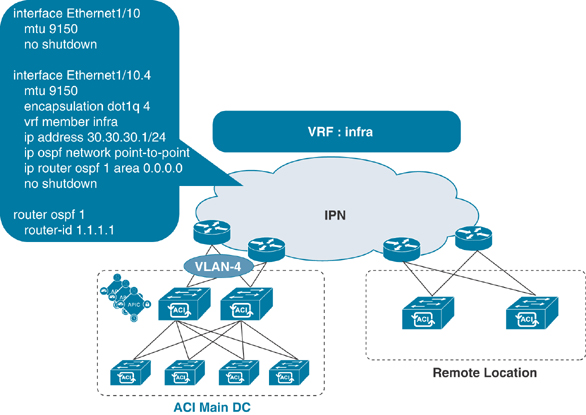
Figure 5-52 Configuration on an Upstream IPN Router at a Main Data Center (Single Pod)
Remote Leaf Connectivity to Multi-Pod Fabric
For remote leaf connectivity to multi-pod fabric, you need to make a few more configurations. First, you must configure the upstream IPN router to a remote leaf by using OSPF with the VLAN-4 subinterface under a separate infra VRF instance. You need to do the same configuration between IPN routers and spines in each pod, much as you do with remote leaf connectivity to a single pod. Then you also need to configure another OSPF peering from IPN routers to spines with VLAN-5 under another separate VRF instance (in this example, rl-mpod) for each pod in the multi-pod fabric. Figure 5-53 illustrates this configuration.

Figure 5-53 Configuration on Upstream IPN Routers at Multiple Pods
Note
This extra configuration is needed for multicast flow symmetry between endpoints connected to remote leafs and the endpoints connected to any pod network in a multi-pod fabric. This scenario is explained in detail in Chapter 4, “ACI Fabric Design Options.” There is no need to create extra OSPF peering with the VLAN-5 configuration with a separate VRF instance at the remote leaf.
1G or 10 Gbps Connectivity from Remote Leaf Switches to Upstream IPN Routers
IPN routers at remote locations may not have 40/100 Gbps link speed options. You might be cornered to connect remote leaf switches with upstream IPN routers using only 1 Gbps or 10 Gbps link speed. In such a case, a QSA adapter can be used to connect remote leaf switches to upstream IPN routers, as shown in Figure 5-54. Please check the latest optics compatibility matrix for QSA support at the Cisco website.

Figure 5-54 Port Speed Options from Remote Leaf to Upstream Router Connectivity
Diagnosing Connectivity Problems
Now that you have learned about various connectivity options in ACI, let’s look at an example of a connectivity issue reported by an application team and how you would diagnose it. Say that members of your application team complain that they cannot access their application. In your initial checking, you find out that the server team has recently plugged in the application server to your ACI fabric. The team has provided you the MAC and IP addresses of the server. Figure 5-55 shows the connectivity problem. What should you do in this case?

Figure 5-55 Server Connectivity Problem
Say that the server is up and sending traffic on a wire; you have confirmed this by examining a Wireshark packet capture on the server. You have also verified that the ACI fabric did not learn the MAC or IP address of the application server through the Endpoint Tracker tool in the APIC. In this case, you should start with physical connectivity or configuration issues.
Perform the following steps to troubleshoot connectivity issues:
Step 1. Check that the server port on the ACI leaf is up.
Step 2. Check the interface profile and ensure that the server port is selected and associated with the correct interface policy group.
Step 3. Ensure that the interface policy group is created with the correct setting for your server (regular access port, port channel, or VPC).
Step 4. Ensure that the AAEP is associated with the interface policy group.
Step 5. Verify that the switch profile has been created.
Step 6. Ensure that the VLAN pool has been created with the encapsulation VLAN that is required for the application server.
Step 7. Ensure that the domain (physical or virtual) has been created and that the VLAN pool is associated.
Figure 5-56 illustrates these troubleshooting steps.

Figure 5-56 ACI Leaf Switch Interface Configuration Verification
Next, you need to look into the logical configuration of the application EPG under the Tenant menu. Follow these steps to ensure that your application server is connected:
Step 1. Ensure that the server EPG is associated with the domain.
Step 2. Ensure that the server port is statically bound with the encapsulation VLAN to server EPG (if it is a bare-metal configuration).
Figure 5-57 illustrates these steps.
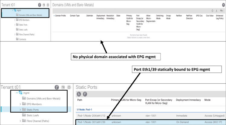
Figure 5-57 ACI Application EPG Configuration Verification
These steps can help you troubleshoot a service downtime problem. In Figure 5-57, notice that there is no physical domain with the mgmt EPG; this is your issue. It is the physical domain that is associated with a VLAN pool where the encapsulation VLAN is defined. The physical domain also gets associated with the AEP, which is part of your interface policies.
Note
Always check the faults and audit logs early in your troubleshooting. If there are any failure events, the fault log will show them. Also, most issues result from configuration changes that either did not go well or did not complete successfully, leaving the network in an unstable state.
Figure 5-58 shows the fault and audit log output.
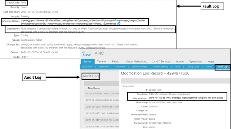
Figure 5-58 ACI Fault Log and Audit Log
Summary
ACI offers numerous end host connectivity options and supports multivendor compute, storage, and network platforms. These connectivity options use industry-standard protocols and allow you to have endpoints reside practically anywhere and everywhere.
In this chapter, you have learned how to connect different compute platforms, such as bare-metal or virtualized compute, in both standalone and blade system format, and you have learned about storage connectivity, L4/L7 service device connectivity, L2/L3 network connectivity, and how to connect multiple pods/sites or remote leafs via IPNs in ACI fabric.
In the next chapter, you will learn about VMM integration.
Review Questions
The questions that follow are designed to help you prepare for the Implementing Cisco Application Centric Infrastructure - Advanced (300-630 DCACIA) exam if you are planning on acquiring the Cisco Certified Specialist: ACI Advanced Implementation certification.
1. How does VPC work in ACI? (Choose three.)
VPC peer-keepalive messages pass through a peer link between two leafs in a VPC domain.
Two leaf switches of any kind can be grouped together to form a VPC domain.
VPC in ACI uses ZeroMQ for control messages.
VPC in ACI does not require a separate physical peer link between leaf switches.
An APIC assigns an auto-generated virtual IP address from the system TEP pool for a VPC leaf pair.
VPC in ACI uses Cisco Fabric Service (CFS) for control messages.
2. What is an access port? What different modes are available for configuring access ports, and how do they differ? (Choose three.)
An access port creates a link bundling for server connectivity.
Access ports are the end host–facing ports, such as ports for servers, IP storage, switches, routers, and L4/L7 devices.
An access port uses the ON mode to connect end hosts.
Access ports can be configured as Trunk, Access (802.1P), or Access (untagged).
Access (802.1P) sends traffic tagged with VLAN 0, whereas Access (untagged) sends traffic without tagging any VLAN.
3. What are the best practices for configuring access policies? (Choose three.)
A clear and meaningful naming standard should be defined and used.
There should be one switch profile individually for each leaf switch for access port configuration, and there should be a separate switch profile for each VPC pair configuration.
A separate VMM domain is required for each tenant.
ACI provides flexibility in using policy object names, and there is no need to define any naming standards.
There should be one physical domain per tenant for bare-metal servers, one for virtual compute, and one for external network connectivity.
4. What is a FEX? What are the limitations of connecting a FEX in ACI? (Choose three.)
A fabric extender (FEX) is a device used to extend switching capability for ease of cable management.
There is no support for external router connectivity using L3Outs on FEX ports.
A remote leaf connected to a FEX is not supported in ACI.
A FEX can connect to only a single leaf.
FCOE is supported on FEX ports connected to all ACI leafs.
5. How does Cisco ACI connect storage devices? What are the limitations? (Choose three.)
ACI creates a Fibre Channel (FC) fabric on leafs using the FC protocol to connect storage.
In ACI, storage-accessing hosts are connected using an F port, and a SAN switch is connected using an NP port configuration on the same leaf.
FCoE traffic in ACI is not forwarded to spine switches.
ACI uses the FCoE protocol on leafs to connect to storage devices.
Storage connectivity is supported on all ACI leaf platforms.
ACI allows multiple VSAN assignments per bridge domain.
6. How does ACI fabric connect to an external bridge network? (Choose three.)
ACI connects to an external bridge network by using the VXLAN protocol.
An external bridge domain helps you extend the entire bridge domain.
ACI statically maps the traditional VLAN to an EPG to extend a bridge network externally.
ACI is a Layer 3 fabric and does not support bridge network connectivity.
In ACI, an EPG can be extended to an external bridge network during application server migration.
7. How does ACI fabric connect to an external routed network? (Choose three.)
External routed network connections support routed interfaces, routed subinterfaces, and SVIs.
An external routed network is configured under a tenant.
For external routed network connectivity, only access port configuration is allowed.
External routed network connectivity using L3Out configuration supports OSPF, BGP, and EIGRP protocols and static routes.
An external routed network is configured using a physical domain.
8. What is GOLF? How is it connected in ACI fabric? (Choose three.)
Only Nexus 9000 devices can be GOLF routers.
VXLAN encapsulation and decapsulation happen on spines in a GOLF solution.
GOLF is an EVPN-based external routed network connectivity solution for scaling VRF instances.
GOLF routers are connected through spines.
The OpFlex control plane automates the fabric-facing VRF configuration on a GOLF router.
9. How is an IPN router connected in an ACI fabric? (Choose three.)
Spine-to-IPN connectivity must be via 40/100 Gbps links.
Spine-to-IPN connectivity is configured under the Infra tenant, using the OSPF routing protocol only.
Spines can be directly connected back-to-back between pods and sites.
All spines are required to connect to IPN routers.
For remote leaf-to-upstream IPN router connectivity, a QSA adapter is required for 1/10 Gbps connections.
Note
There are no Key Topics for this chapter.