
Chapter 6
VMM Integration
Cisco ACI virtual machine (VM) networking supports hypervisors from multiple vendors. It allows for multivendor hypervisors along with programmable and automated access to high-performance scalable virtualized data center infrastructure. In this chapter, you will learn about Virtual Machine Manager (VMM) and its integration into Cisco Application Centric Infrastructure (ACI) from the following virtualization-supported products and vendors:
You will also learn about VMM integration with ACI at multiple locations.
Virtual Machine Manager (VMM)
VMM integration enables the ACI fabric to extend network policies and policy group definitions into the virtualization switching layer on end hosts. This integration automates critical network plumbing steps that typically create delays in the deployment of overall virtual and compute resources in legacy network environments. VMM integration into ACI also provides value in getting visibility up to the virtualization layer of the application, which is a perpetually conflicting factor between network and server virtualization teams.
VMM Domain Policy Model
VMM domain profiles (vmmDomP) specify connectivity policies that enable virtual machine controllers to connect to the ACI fabric. Figure 6-1 shows the general hierarchy of VMM configuration.

Figure 6-1 VMM Policy Model
VMM Domain Components
VMM domains enable an administrator to configure connectivity policies for virtual machine controllers in ACI. The essential components of an ACI VMM domain policy include the following:
VMM domain
VLAN pool association
Attachable access entity profile association
VMM domain endpoint group (EPG) association
VMM Domains
VMM domains make it possible to group VM controllers with similar networking policy requirements. For example, VM controllers can share VLAN pools and application EPGs. The Cisco Application Policy Infrastructure Controller (APIC) communicates with the VM controller to publish network configurations such as port groups, which are then applied to the virtual workloads. The VMM domain profile includes the following essential components:
Credential: Associates a valid VM controller user credential with an APIC VMM domain.
Controller: Specifies how to connect to a VM controller that is part of a policy enforcement domain. For example, the controller specifies the connection to a VMware vCenter instance that is part of a VMM domain.
Note
A single VMM domain can contain multiple instances of VM controllers, but they must be from the same vendor (for example, VMware, Microsoft).
An APIC VMM domain profile is a policy that defines a VMM domain. The VMM domain policy is created on an APIC and pushed into the leaf switches. Figure 6-2 illustrates VM controllers of the same vendor as part of the same VMM domain.
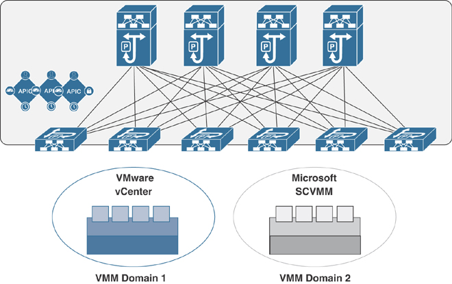
Figure 6-2 VMM Domain Integration
VMM domains provide the following:
A common layer in the ACI fabric that enables scalable fault-tolerant support for multiple VM controller platforms.
VMM support for multiple tenants within the ACI fabric.
VMM domains contain VM controllers such as VMware vCenter or Microsoft System Center Virtual Machine Manager (SCVMM) and the credentials required for the ACI API to interact with the VM controllers. A VMM domain enables VM mobility within the domain but not across domains. A single VMM domain can contain multiple instances of VM controllers, but they must be from the same vendor. For example, a VMM domain can contain many VMware vCenter instances managing multiple controllers, each running multiple VMs; however, it cannot contain Microsoft SCVMM instances. A VMM domain inventories controller elements (such as pNICs, vNICs, and VM names) and pushes policies into the controllers, creating port groups or VM networks and other necessary elements. The ACI VMM domain listens for controller events such as VM mobility events and responds accordingly.
VMM Domain VLAN Pool Association
A VLAN pool specifies a single VLAN ID or a range of VLAN IDs for VLAN encapsulation. It is a shared resource that can be consumed by multiple domains, such as physical, VMM, or external domains.
In ACI, you can create a VLAN pool with allocation type static or dynamic. With static allocation, the fabric administrator configures a VLAN; with dynamic allocation, the APIC assigns the VLAN to the domain dynamically. In ACI, only one VLAN or VXLAN pool can be assigned to a VMM domain.
A fabric administrator can assign a VLAN ID statically to an EPG. However, in this case, the VLAN ID must be included in the VLAN pool with the static allocation type, or the APIC will generate a fault. By default, the assignment of VLAN IDs to EPGs that are associated with the VMM domain is done dynamically by the APIC. The APIC provisions VMM domain VLAN IDs on leaf switch ports based on EPG events, either statically binding or based on VM events from controllers such as VMware vCenter or Microsoft SCVMM.
Attachable Access Entity Profile Association
An attachable access entity profile (AAEP) associates a VMM domain with the physical network infrastructure where the vSphere hosts are connected. The AAEP defines which VLANs will be permitted on a host-facing interface. When a domain is mapped to an endpoint group, the AAEP validates that the VLAN can be deployed on certain interfaces. An AAEP is a network interface template that enables the deployment of VM controller policies on a large set of leaf switch ports. An AAEP specifies which switches and ports are available and how they are configured. The AAEP can be created on-the-fly during the creation of the VMM domain itself.
VMM Domain EPG Association
Endpoint groups regulate connectivity and visibility among the endpoints within the scope of the VMM domain policy. VMM domain EPGs behave as follows:
The APIC pushes these EPGs as port groups into the VM controller.
An EPG can span multiple VMM domains, and a VMM domain can contain multiple EPGs.
The ACI fabric associates EPGs to VMM domains, either automatically through an orchestration component such as VMware vRealize suite (vRA/vRO) or Microsoft Azure, or when an APIC administrator creates such configurations. An EPG can span multiple VMM domains, and a VMM domain can contain multiple EPGs.
In Figure 6-3, endpoints (EPs) of the same color are part of the same EPG. For example, all the gray EPs are in the same EPG, even though they are in different VMM domains.

Figure 6-3 VMM Domain EPG Association
Note
Refer to the latest Verified Scalability Guide for Cisco ACI at the Cisco website for virtual network and VMM domain EPG capacity information.
Figure 6-4 illustrates multiple VMM domains connecting to the same leaf switch if they do not have overlapping VLAN pools on the same port. Similarly, the same VLAN pools can be used across different domains if they do not use the same port of a leaf switch.
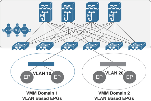
Figure 6-4 VMM Domain EPG VLAN Consumption
EPGs can use multiple VMM domains in the following ways:
An EPG within a VMM domain is identified by an encapsulation identifier that is either automatically managed by the APIC or statically selected by the administrator. An example for a VLAN is a virtual network ID (VNID).
An EPG can be mapped to multiple physical (for bare-metal servers) or virtual domains. It can use different VLAN or VNID encapsulations in each domain.
Note
By default, an APIC dynamically manages the allocation of a VLAN for an EPG in a VMM integration. VMware vSphere Distributed Switch (VDS) administrators have the option of configuring a specific VLAN for an EPG. In that case, the VLAN is chosen from a static allocation block within the pool associated with the VMM domain.
Applications can be deployed across VMM domains, as illustrated in Figure 6-5. While live migration of VMs within a VMM domain is supported, live migration of VMs across VMM domains is not supported.

Figure 6-5 Multiple VMM Domains and Scaling of EPGs in the ACI Fabric
EPG Policy Resolution and Deployment Immediacy
Whenever an EPG associates to a VMM domain, the administrator can choose the policy resolution and deployment preferences to specify when it should be pushed and programmed into leaf switches. This approach provides efficient use of hardware resources because resources are consumed only when demanded. You should be aware of picking one option over the other, depending on the use case and scalability limits of your ACI infrastructure, as explained in the following sections.
Resolution Immediacy
The Resolution Immediacy option defines when policies are downloaded to the leaf software based on the following options:
Pre-provision: This option specifies that a policy (such as VRF, VLAN, VXLAN binding, contracts, or filters) is downloaded to the associated leaf switch software even before a VM controller is attached to the distributed virtual switch (DVS), such as a VMware (VDS), defined by an APIC through the VMM domain.
This option helps when management traffic between hypervisors and VM controllers such as VMware vCenter is also using the APIC-defined virtual switch.
When you deploy a VMM policy such as VLAN or VXLAN on an ACI leaf switch, an APIC must collect CDP/LLDP information from hypervisors through the VM controller and ACI leaf switch to which the host is connected. However, if the VM controller is supposed to use the same VMM policy to communicate with its hypervisors or even an APIC, the CDP/LLDP information for hypervisors can never be collected because the required policy is not deployed yet.
With the Pre-provision immediacy option, policy is downloaded to the ACI leaf switch software, regardless of CDP/LLDP neighborship and even without a hypervisor host connected to the VMM domain-defined DVS.
Immediate: This option specifies that a policy (such as VRF, VLAN, VXLAN binding, contracts, or filters) is downloaded to the associated leaf switch software upon ESXi host attachment to a DVS. LLDP or OpFlex permissions are used to resolve the VM controller to leaf switch attachments.
The policy is downloaded to a leaf when you add a host to the VMM domain-defined DVS. CDP/LLDP neighborship from host to leaf is required.
On Demand: This option specifies that a policy (such as VRF, VLAN, VXLAN binding, contracts, or filters) is pushed to the leaf node only when a host running hypervisor is attached to a DVS and a VM is placed in the port group (EPG).
The policy is downloaded to a leaf when a host is added to the VMM domain-defined DVS and a virtual machine is placed in the port group (EPG). CDP/LLDP neighborship from host to leaf is required.
With both the Immediate and On Demand options for resolution immediacy, if the hypervisor running on the host and leaf lose LLDP/CDP neighborship, the policies are removed from the leaf switch software.
Deployment Immediacy
After the policies are downloaded to the leaf software through the Resolution Immediacy option, you can use Deployment Immediacy to specify when the policy is pushed to the hardware policy content-addressable memory (CAM). Two options are available:
Immediate: This option specifies that the policy is programmed into the hardware policy CAM as soon as the policy is downloaded in the leaf software. You should be aware of your ACI infrastructure scalability limits when choosing this option.
On Demand: This option specifies that the policy is programmed in the hardware policy CAM only when the first packet is received through the data path. This process helps optimize the hardware resources.
Note
When you use On Demand deployment immediacy with MAC-pinned VPCs, the EPG contracts are not pushed to the leaf ternary content-addressable memory (TCAM) until the first endpoint is learned in the EPG on each leaf. This can cause uneven TCAM utilization across VPC peers. (Normally, the contract would be pushed to both peers.)
VMware Integration
When integrating your VMware infrastructure into Cisco ACI, you have two options for deploying virtual networking:
VMware vSphere Distributed Switch (VDS)
Cisco Application Virtual Switch (AVS)
These two options provide similar basic virtual networking functionality; however, the AVS option provides additional capabilities, such as VXLAN and microsegmentation support.
Prerequisites for VMM Integration with AVS or VDS
The prerequisites for VMM integration with AVS or VDS are as follows:
You need to decide whether to use VLAN or VXLAN encapsulation or multicast groups.
A virtual machine manager must be already deployed, such as vCenter.
The VMM must be accessible by the APIC through either the out-of-band or in-band management network.
For Cisco AVS deployment, a vSphere Installation Bundle (VIB) must be installed on all hypervisor hosts to be added to the AVS.
For a VXLAN deployment, you need to know whether intermediate devices have Internet Group Management Protocol (IGMP) snooping on or off by default.
Guidelines and Limitations for VMM Integration with AVS or VDS
The guidelines and limitations for VMM integration with AVS or VDS are as follows:
When utilizing VLANs for VMM integration, whether with Cisco AVS or VMware VDS, the range of VLANs to be used for port groups must be manually allowed on any intermediate devices.
For VMM integration with VLANs and the Resolution Immediacy setting On Demand or Immediate, there can be a maximum of one hop between a host and the compute node.
For VMM integration with VXLAN, only the infrastructure VLAN needs to be allowed on all intermediate devices.
For VMM integration with VXLAN, if the Infra bridge domain subnet is set as a querier, the intermediate devices must have IGMP snooping enabled for traffic to pass properly.
To log in to the APIC GUI, choose Tenants > Infra > Networking > Bridge Domains > default > Subnets > 10.0.0.30/27.
For VMM integration with VXLAN and UCS-B, IGMP snooping is enabled on the UCS-B by default. Therefore, you need to ensure that the querier IP address is enabled for the Infra bridge domain. The other option is to disable IGMP snooping on the UCS and disable the querier IP address on the Infra bridge domain.
ACI VMM Integration Workflow
Figure 6-6 illustrates the ACI VMM integration workflow steps.

Figure 6-6 ACI VMM Integration Workflow
Publishing EPGs to a VMM Domain
This section details how to publish an existing EPG to a VMM domain. For an EPG to be pushed to a VMM domain, you must create a domain binding within the tenant EPG by following these steps:
Step 1. From the menu bar, choose Tenants > All Tenants.
Step 2. From the Work pane, choose the Tenant_Name.
Step 3. From the Navigation pane, choose Tenant_Name > Application Profiles > Application_Profile_Name > Application EPGs > Application_EPG_Name > Domains (VMs and bare-metal servers).
Step 4. From the Work pane, choose Actions > Add VM Domain Association.
Step 5. In the Add VM Domain Association dialog box, choose the VMM domain profile that you created previously. For Deployment and Resolution Immediacy, Cisco recommends keeping the default option, On Demand. This provides the best resource usage in the fabric by deploying policies to leaf nodes only when endpoints assigned to this EPG are connected. There is no communication delay or traffic loss when you keep the default selections.
Step 6. Click Submit. The EPG is now available as a port group to your VMM.
Connecting Virtual Machines to the Endpoint Group Port Groups on vCenter
To connect virtual machines to the endpoint group port groups on vCenter, do the following:
Step 1. Connect to vCenter by using the VMware VI Client.
Step 2. From the Host and Clusters view, right-click on your virtual machine and choose Edit Settings.
Step 3. Click on the network adapter and from the Network Connection drop-down box, choose the port group that corresponds to your EPG. It should appear in the format of TENANT | APPLICATION_PROFILE | EPG | VMM_DOMAIN_PROFILE.
If you do not see your Cisco ACI EPG in the Network Connection list, it means one of the following:
The VM is running on a host that is not attached to the distributed switch managed by the APIC.
There may be a communication between your APIC and vCenter either through the OOB or the INB management network.
Verifying VMM Integration with the AVS or VDS
The following sections describe how to verify that the Cisco AVS has been installed on the VMware ESXi hypervisor.
Verifying the Virtual Switch Status
To verify the virtual switch status, follow these steps:
Step 1. Log in to the VMware vSphere client.
Step 2. Choose Networking.
Step 3. Open the folder for the data center and click the virtual switch.
Step 4. Click the Hosts tab. The VDS Status and Status fields display the virtual switch status. Ensure that the VDS status is Up, which indicates that OpFlex communication has been established.
Verifying the vNIC Status
To verify the vNIC status, follow these steps:
Step 1. In the VMware vSphere client, click the Home tab.
Step 2. Choose Hosts and Clusters.
Step 3. Click the host.
Step 4. In the Configuration tab, select the Hardware panel and choose Networking.
Step 5. In the View field, click the vSphere Distributed Switch button.
Step 6. Click Manage Virtual Adapters. The vmk1 displays as a virtual adapter with an IP address.
Step 7. Click the newly created vmk interface to display the vmknic status.
Note
Allow approximately 20 seconds for the vmk to receive an IP address through DHCP.
Microsoft SCVMM Integration
Figure 6-7 shows a representative topology for a Microsoft SCVMM integration with Cisco ACI. Hyper-V clustering connectivity between SCVMM virtual machines and the APIC can run over the management network.

Figure 6-7 Microsoft SCVMM Topology with ACI
Figure 6-8 illustrates the workflow for integrating Microsoft SCVMM with Cisco ACI. The following sections describe the steps in this workflow.

Figure 6-8 Workflow for Integrating ACI and Microsoft SCVMM
Mapping ACI and SCVMM Constructs
Figure 6-9 shows the mapping of Cisco ACI and the SCVMM constructs (SCVMM controller, cloud, and logical switches).
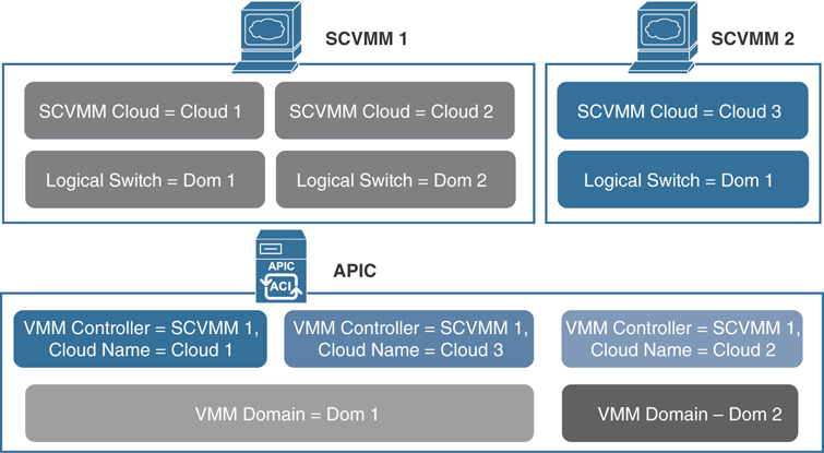
Figure 6-9 Mapping ACI and SCVMM Constructs
One VMM domain cannot map to the same SCVMM more than once. An APIC can be associated with up to five SCVMM controllers. For additional information on other limitations, see the Verified Scalability Guide for Cisco ACI on the Cisco website.
Mapping Multiple SCVMMs to an APIC
When multiple SCVMMs are associated with an APIC, the OpFlex certificate from the first SCVMM controller must be copied to the secondary controller and other controllers, as applicable. You use the certlm.msc command on the local SCVMM controller to import the certificate to the following location:
Certificates - Local Computer > Personal > Certificates
The same OpFlex certificate is deployed on the Hyper-V servers that are managed by this SCVMM controller. You use the mmc command to install the certificate on the Hyper-V servers.
Verifying That the OpFlex Certificate Is Deployed for a Connection from the SCVMM to the APIC
You can verify that the OpFlex certificate is deployed for a connection from the SCVMM to the APIC by viewing the Cisco_APIC_SCVMM_Service log file, which is located in the C:Program Files (x86)ApicVMMServiceLogs directory. In this file, ensure that the correct certificate is used and also check to make sure there was a successful login to the APIC (see Example 6-1).
Example 6-1 Viewing the Cisco_APIC_SCVMM_Service Log File
4/15/2017 2:10:09 PM-1044-13||UpdateCredentials|| AdminSettingsController:
  UpdateCredentials.
4/15/2017 2:10:09 PM-1044-13||UpdateCredentials|| new: EndpointAddress:
  Called_from_SCVMMM_PS,
  Username ApicAddresses 10.10.10.1;10.10.10.2;10.10.10.3 CertName: OpflexAgent
4/15/2017 2:10:09 PM-1044-13||UpdateCredentials|| ########
4/15/2017 2:10:09 PM-1044-13||UpdateCredentials|| oldreg_apicAddresses is
4/15/2017 2:10:09 PM-1044-13||UpdateCredentials|| Verifying APIC address 10.10.10.1
4/15/2017 2:10:09 PM-1044-13||GetInfoFromApic|| Querying URL https://192.168.10.10/
  api/node/class/infraWiNode.xml
4/15/2017 2:10:09 PM-1044-13||GetInfoFromApic|| HostAddr 10.10.10.1
4/15/2017 2:10:09 PM-1044-13||PopulateCertsAndCookies|| URL:/api/node/class/
  infraWiNode.xml
4/15/2017 2:10:09 PM-1044-13||PopulateCertsAndCookies|| Searching Cached Store
  Name: My
4/15/2017 2:10:09 PM-1044-13||PopulateCertsAndCookies|| Using Certificate
  CN=OpflexAgent, C=USA, S=MI, O=CX, [email protected] in Cached Store Name:My
4/15/2017 2:10:09 PM-1044-13||PopulateCertsAndCookies|| Using the following CertDN:
  uni/userext/user-admin/usercert-OpFlexAgent
4/15/2017 2:10:09 PM-1044-13||GetInfoFromApic|| IFC returned OK to deployment query
4/15/2017 2:10:09 PM-1044-13||GetInfoFromApic|| Successfully deserialize deployment
  query response
4/15/2017 2:10:09 PM-1044-13||UpdateCredentials|| ApicClient.Login(addr 10.10.10.1)
  Success.
Verifying VMM Deployment from the APIC to the SCVMM
You can verify that the OpFlex certificate is deployed on the Hyper-V server by viewing log files in the C:Program Files (x86)ApicHyperAgentLogs directory. In this file, ensure that the correct certificate is used and ensure that the connection with the Hyper-V servers on the fabric leafs is established. In addition, ensure that a VTEP virtual network adapter is added to the virtual switch and an IP address is assigned to the VTEP adapter.
In the SCVMM, check for the following:
Under Fabric > Logical Switches, verify that apicVswitch_VMMdomainName is deployed from the APIC to the SCVMM.
Under Fabric > Logical Networks, verify that apicLogicalNetwork_VMMdomainName is deployed from the APIC to the SCVMM.
Under Fabric > Port Profiles, verify that apicUplinkPortProfile_VMMdomainName is deployed. If it is not deployed, right-click the host under Servers and choose Properties. Go to Virtual Switches and ensure that the physical adapters are attached to the virtual switches.
Note
In the APIC GUI, the Hyper-V servers and the virtual machines do not appear in the Microsoft SCVMM inventory until you ensure that these points for the SCVMM are satisfied.
OpenStack Integration
OpenStack defines a flexible software architecture for creating cloud-computing environments. The reference software-based implementation of OpenStack allows for multiple Layer 2 transports, including VLAN, GRE, and VXLAN. The Neutron project within OpenStack can also provide software-based Layer 3 forwarding. When OpenStack is used with ACI, the ACI fabric provides an integrated Layer 2/3 VXLAN-based overlay networking capability that can offload network encapsulation processing from the compute nodes to the top-of-rack or ACI leaf switches. This architecture provides the flexibility of software overlay networking in conjunction with the performance and operational benefits of hardware-based networking.
Extending OpFlex to the Compute Node
OpFlex is an open and extensible policy protocol designed to transfer declarative networking policies such as those used in Cisco ACI to other devices. By using OpFlex, you can extend the policy model native to ACI all the way down into the virtual switches running on OpenStack Nova compute hosts. This OpFlex extension to the compute host allows ACI to use Open vSwitch (OVS) to support common OpenStack features such as source Network Address Translation (SNAT) and floating IP addresses in a distributed manner.
The ACI OpenStack drivers support two distinct modes of deployment. The first approach is based on the Neutron API and Modular Layer 2 (ML2), which are designed to provide common constructs such as network, router, and security groups that are familiar to Neutron users. The second approach is native to the group-based policy abstractions for OpenStack, which are closely aligned with the declarative policy model used in Cisco ACI.
ACI with OpenStack Physical Architecture
A typical architecture for an ACI fabric with an OpenStack deployment consists of a Nexus 9000 spine/leaf topology, an APIC cluster, and a group of servers to run the various control and compute components of OpenStack. An ACI external routed network connection as a Layer 3 connection outside the fabric can be used to provide connectivity outside the OpenStack cloud. Figure 6-10 illustrates OpenStack infrastructure connectivity with ACI.
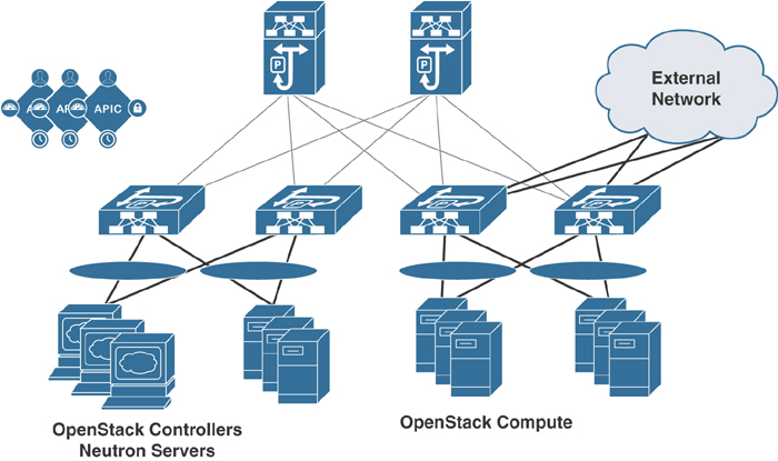
Figure 6-10 OpenStack Physical Topology with ACI
OpFlex Software Architecture
The ML2 framework in OpenStack enables the integration of networking services based on type drivers and mechanism drivers. Common networking type drivers include local, flat, VLAN, and VXLAN. OpFlex is added as a new network type through ML2, with an actual packet encapsulation of either VXLAN or VLAN on the host defined in the OpFlex configuration. A mechanism driver is enabled to communicate networking requirements from the Neutron servers to the Cisco APIC cluster. The APIC mechanism driver translates Neutron networking elements such as a network (segment), subnet, router, or external network into APIC constructs in the ACI policy model.
The OpFlex software stack also currently utilizes OVS and local software agents on each OpenStack compute host that communicates with the Neutron servers and OVS. An OpFlex proxy from the ACI leaf switch exchanges policy information with the agent OVS instance in each compute host, effectively extending the ACI switch fabric and policy model into the virtual switch. Figure 6-11 illustrates the OpenStack architecture with OpFlex in ACI.
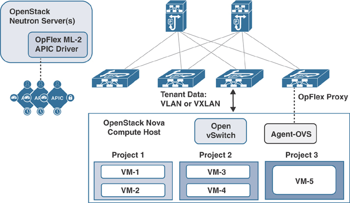
Figure 6-11 OpenStack Architecture with OpFlex in ACI
OpenStack Logical Topology
The logical topology diagram in Figure 6-12 illustrates the connections to OpenStack network segments from Neutron/controller servers and compute hosts, including the distributed Neutron services.

Figure 6-12 OpenStack Logical Topology in ACI
Note
The management/API network for OpenStack can be connected to servers using an additional virtual NIC/subinterface on a common uplink with tenant networking to the ACI fabric, or by way of a separate physical interface.
Mapping OpenStack and ACI Constructs
Cisco ACI uses a policy model to enable network connectivity between endpoints attached to the fabric. OpenStack Neutron uses more traditional Layer 2 and Layer 3 networking concepts to define networking configuration. The OpFlex ML2 driver translates the Neutron networking requirements into the necessary ACI policy model constructs to achieve the desired connectivity. The OpenStack Group-Based Policy (GBP) networking model is quite similar to the Cisco ACI policy model. With the Cisco ACI unified plug-in for OpenStack, you can use both ML2 and GBP models on a single plug-in instance.
Note
Only ML2 or GBP can be used for any given OpenStack project. A single project should not mix ML2 and GBP configurations.
Table 6-1 illustrates the OpenStack Neutron constructs and the corresponding APIC policy objects that are configured when they are created. In the case of GBP deployment, the policies have a direct mapping to the ACI policy model. Table 6-2 shows the OpenStack GBP objects and their corresponding ACI objects.
Table 6-1 OpenStack Neutron Objects and Corresponding APIC Objects
Neutron Object |
APIC Object |
(Neutron Instance) |
VMM Domain |
Project |
Tenant + Application Network Profile |
Network |
EPG + Bridge Domain |
Subnet |
Subnet |
Security Group + Rule |
N/A (Iptables rules maintained per host) |
Router |
Contract |
Network:external |
L3Out/Outside EPG |
Table 6-2 OpenStack GBP Objects and Corresponding APIC Objects
GBP Object |
APIC Object |
Policy Target |
Endpoint |
Policy Group |
Endpoint Group (fvAEPg) |
Policy Classifier |
Filter (vzFilter) |
Policy Action |
-- |
Policy Rule |
Subject (vzSubj) |
Policy Ruleset |
Contract (vzBrCP) |
L2 Policy |
Bridge Domain (fvBD) |
L3 Policy |
Context (fvCtx) |
Prerequisites for OpenStack and Cisco ACI
Keep in mind the following prerequisites for OpenStack and Cisco ACI:
Target audience: It is important to have working knowledge of Linux, the intended OpenStack distribution, the ACI policy model, and GUI-based APIC configuration.
ACI Fabric: ACI fabric needs to be installed and initialized with a minimum APIC version 1.1(4e) and NX-OS version 11.1(4e). For basic guidelines on initializing a new ACI fabric, see the relevant documentation. For communication between multiple leaf pairs, the fabric must have a BGP route reflector enabled to use an OpenStack external network.
Compute: You need to have a controller and servers connected to the fabric, preferably using NIC bonding and a VPC. In most cases the controller does not need to be connected to the fabric.
L3Out: For external connectivity, one or more Layer 3 Outs (L3Outs) need to be configured on the ACI.
VLAN mode: For VLAN mode, a non-overlapping VLAN pool of sufficient size should be allocated ahead of time.
Guidelines and Limitations for OpenStack and Cisco ACI
The following sections describes the guidelines and limitations for OpenStack and Cisco ACI.
Scalability Guidelines
There is a one-to-one correlation between the OpenStack tenant and the ACI tenant, and for each OpenStack tenant, the plug-in automatically creates ACI tenants named according to the following convention:
convention_apic_system_id_openstack_tenant_name
You should consider the scalability parameters for supporting the number of required tenants.
It is important to calculate the fabric scale limits for endpoint groups, bridge domains, tenants, and contracts before deployment. Doing so limits the number of tenant/project networks and routers that can be created in OpenStack. There are per-leaf and per-fabric limits. Make sure to check the scalability parameters for the deployed release before deployment. In the case of GBP deployment, it can take twice as many endpoint groups and bridge domains as with ML2 mode. Table 6-3 and Table 6-4 list the APIC resources that are needed for each OpenStack resource in GBP and ML2 configurations.
Table 6-3 OpenStack GBP and ACI Resources
GBP Resource |
APIC Resources Consumed |
L3 policy |
One context |
L2 policy |
One bridge domain One endpoint group Two contracts |
Policy group |
One endpoint group |
Ruleset |
One contract |
Classifier |
Two filters (forward and reverse) Note: Five overhead classifiers are created |
Table 6-4 OpenStack ML2 and ACI Resources
ML2 Resource |
APIC Resources Consumed |
Network |
One bridge domain One endpoint group |
Router |
One contract |
Security groups |
N/A (no filters are used) |
Availability Guidelines
For redundancy, you can use bonded interfaces (VPCs) by connecting two interfaces to two leaf switches and creating a VPC in ACI. You should deploy redundant OpenStack controller nodes to avoid a single point of failure. The external network should also be designed to avoid a single point of failure and service interruption.
NAT/External Network Operations
The OpFlex driver software can support external network connectivity and Network Address Translation (NAT) functions in a distributed manner using the local OVS instance on each OpenStack compute node. This distributed approach increases the availability of the overall solution and offloads the central processing of NAT from the Neutron server Layer 3 agent that is used in the reference implementation. You can also provide direct external connectivity without NAT or with a mix of NAT and non-NAT external connectivity.
Subnets Required for NAT
Unlike with the standard Neutron approach, three distinct IP subnets are required to take full advantage of external network functionality with the OpFlex driver:
Link subnet: This subnet represents the actual physical connection to the external next-hop router outside of the fabric to be assigned to a routed interface, subinterface, or SVI.
Source NAT subnet: This subnet is used for Port Address Translation (PAT), allowing multiple virtual machines to share an outside-routable IP address. A single IP address is assigned to each compute host, and Layer 4 port number manipulation is used to maintain unique session traffic.
Floating IP subnet: With OpenStack, the term floating IP is used when a virtual machine instance is allowed to claim a distinct static NAT address to support inbound connections to the virtual machine from outside the cloud. The floating IP subnet is the subnet assigned within OpenStack to the Neutron external network entity.
Optimized DHCP and Metadata Proxy Operations
The OpFlex driver software stack provides optimized traffic flow and distributed processing to provide DHCP and metadata proxy services for virtual machine instances. These services are designed to keep processing and packet traffic local to the compute host as much as possible. The distributed elements communicate with centralized functions to ensure system consistency. You should enable optimized DHCP and metadata services when deploying the OpFlex plug-in for OpenStack.
Physical Interfaces
OpFlex uses the untagged fabric interface for an uplink trunk in VLAN mode. This means the fabric interface cannot be used for PXE because PXE usually requires an untagged interface. If you require PXE in a VLAN mode deployment, you must use a separate interface for PXE. This interface can be connected through ACI or an external switch. This issue is not present in VXLAN mode since tunnels are created using the tagged interface for an infrastructure VLAN.
Layer 4 to Layer 7 Services
Service insertion in OpenStack is done through a physical domain or device package. You should check customer requirements and the plug-in mode (GBP or ML2) to plan how service insertion/chaining will be done. The OpenStack Neutron project also defines Layer 4 to Layer 7 extension APIs, such as LBaaS, FWaaS, and VPNaaS. The availability of these extensions depends on the device vendor. Check the vendor for the availability of these extensions.
Blade Servers
When deploying on blade servers, you must make sure there is no intermediate switch between the fabric and the physical server interfaces. Check the OpenStack ACI plug-in release notes to make sure a particular configuration is supported. At this writing, there is limited support for B-Series blade servers, and the support is limited to VLAN mode only.
Verifying the OpenStack Configuration
Follow these steps to verify the OpenStack configuration:
Step 1. Verify that a VMM domain was created for the OpenStack system ID defined during installation. The nodes connected to the fabric that are running the OpFlex agent should be visible under Hypervisors. The virtual machines running on the hypervisor should be visible when you select that hypervisor. All networks created for this tenant should also be visible under the DVS submenu, and selecting the network should show you all endpoints connected to that network.
Step 2. Look at the health score and faults for the entity to verify correct operation. If the hypervisors are not visible or appear as being disconnected, check the OpFlex connectivity.
Step 3. Verify that there is a tenant created for the OpenStack tenant/project. All the networks created in OpenStack should show up as endpoint groups and corresponding bridge domains. Choose the Operational tab for the endpoint group to see all of the endpoints for that endpoint group.
Step 4. Check the Health Score tab and Faults tab to make sure there are no issues.
Configuration Examples for OpenStack and Cisco ACI
The following sections provide configuration examples for OpenStack and Cisco ACI.
Optimized Metadata and DHCP
In the configuration file, optimized DHCP is enabled by default in the OpFlex OpenStack plug-in. To disable optimized DHCP, add the following line:
enable_optimized_dhcp = False
In the configuration file, the optimized metadata service is disabled by default. To enable the optimized metadata, add the following line:
enable_optimized_metadata = True
External Network/NAT Configuration
You can define external network connectivity by adding an apic_external_network section to the configuration file, as in this example:
[apic_external_network:DC-Out]
preexisting=True
external_epg=DC-Out-EPG
host_pool_cidr=10.10.10.1/24
In this example, host_pool_cidr defines the SNAT subnet. You define the floating IP subnet by creating an external network in Neutron or an external policy in GBP. The name of the external network or policy should use the same name as apic_external_network that is defined in the file (in this case, DC-Out).
It is possible to disable NAT by adding enable_nat = False in the apic_external_network section. You can have multiple external networks using different Layer 3 Outs on ACI, and you can have a mix of NAT and non-NAT external networks.
In GBP deployment, network subnets for policy groups are carved out of the default_ip_pool setting defined in the plug-in configuration file, as in this example:
[group_policy_implicit_policy]
default_ip_pool = 192.168.10.0/16
This pool is used to allocate networks for created policy groups. You must make sure that the pool is large enough for the intended number of groups.
Kubernetes Integration
Kubernetes is a portable, extensible open-source platform that automates the deployment, scaling, and management of container-based workloads and services in a network. Beginning with Cisco APIC Release 3.0(1), you can integrate Kubernetes on bare-metal servers into Cisco ACI.
To integrate Kubernetes with Cisco ACI, you need to execute a series of tasks. Some of them you perform in the network to set up the Cisco APIC; others you perform on the Kubernetes server. Once you have integrated Kubernetes, you can use the Cisco APIC to view Kubernetes in the Cisco ACI.
Note
The following sections show the workflow for integrating Kubernetes and provide specific instructions for setting up the Cisco APIC. However, it is assumed that you are familiar with Kubernetes and containers and can install Kubernetes. Specific instructions for installing Kubernetes are beyond the scope of this book.
The following are the basic tasks involved in integrating Kubernetes into the Cisco ACI fabric:
Step 1. Prepare for the integration and set up the subnets and VLANs in the network.
Step 2. Fulfill the prerequisites.
Step 3. To provision the Cisco APIC to integrate with Kubernetes, download the provisioning tool, which includes a sample configuration file, and update the configuration file with information you previously gathered about your network. Then run the provisioning tool with the information about your network.
Step 4. Set up networking for the node to support Kubernetes installation. This includes configuring an uplink interface, subinterfaces, and static routes.
Step 5. Install Kubernetes and Cisco ACI containers.
Step 6. Use the Cisco APIC GUI to verify that Kubernetes has been integrated into Cisco ACI.
The following sections provide details on these steps.
Planning for Kubernetes Integration
Various network resources are required to provide capabilities to a Kubernetes cluster, including several subnets and routers. You need the following subnets:
Node subnet: This subnet is used for Kubernetes control traffic. It is where the Kubernetes API services are hosted. Make the node subnet a private subnet and make sure that it has access to the Cisco APIC management address.
Pod subnet: This is the subnet from which the IP addresses of Kubernetes pods are allocated. Make the pod subnet a private subnet.
Note
This subnet specifies the starting address for the IP pool that is used to allocate IP addresses to pods and your Cisco ACI bridge domain IP address. For example, if you define it as 192.168.255.254/16, this is a valid configuration from a Cisco ACI perspective. However, your containers will not get an IP address because there are no free IP addresses after 192.168.255.254 in this subnet. We suggest always using the first IP address in the pod subnet, which in this example would be 192.168.0.1/16.
Node service subnet: This subnet is used for internal routing of load-balanced service traffic. Make the node service subnet a private subnet.
Note
Much as with the pod subnet, you should configure the service subnet with the first IP address of the allocated subnet.
External service subnets: These subnets are pools from which load-balanced services are allocated as externally accessible service IP addresses.
Note
The externally accessible service IP addresses could be globally routable. You should configure the next-hop router to send traffic destined for these IP addresses to the fabric. There are two such pools: One is used for dynamically allocated IP addresses, and the other is available for services to request a specific fixed external IP address.
You need the following VLANs for local fabric use:
Node VLAN: This VLAN is used by the physical domain for Kubernetes nodes.
Service VLAN: This VLAN is used for delivery of load-balanced service traffic.
Infrastructure VLAN: This is the infrastructure VLAN used by the Cisco ACI fabric.
Prerequisites for Integrating Kubernetes with Cisco ACI
Ensure that the following prerequisites are in place before you try to integrate Kubernetes with the Cisco ACI fabric:
A working Cisco ACI installation
An attachable entity profile (AEP) set up with interfaces that are desired for the Kubernetes deployment
An L3Out connection, along with a Layer 3 external network to provide external access
Virtual routing and forwarding (VRF)
Note
The VRF and L3Out connection in Cisco ACI that are used to provide outside connectivity to Kubernetes external services can be in any tenant. The most common usage is to put the VRF and L3Out in the common tenant or in a tenant that is dedicated to the Kubernetes cluster. You can also have separate VRFs—one for the Kubernetes bridge domains and one for the L3Out—and you can configure route leaking between them.
Any required route reflector configuration for the Cisco ACI fabric
A next-hop router that is connected to the Layer 3 external network and that is capable of appropriate external access and configured with the required routes
In addition, the Kubernetes cluster must be up through the fabric-connected interface on all the hosts. The default route should be pointing to the ACI node subnet bridge domain. This is not mandatory, but it simplifies the routing configuration on the hosts and is the recommend configuration. If you choose not to use this design, all Kubernetes-related traffic must go through the fabric.
Provisioning Cisco ACI to Work with Kubernetes
You can use the acc_provision tool to provision the fabric for the Kubernetes VMM domain and generate a .yaml file that Kubernetes uses to deploy the required Cisco ACI container components. The procedure to accomplish this is as follows:
Step 1. Download the provisioning tool from
https://software.cisco.com/download/type.html?mdfid=285968390&i=rm and then follow these steps:
Click APIC OpenStack and Container Plugins.
Choose the package that you want to download.
Click Download.
Step 2. Generate a sample configuration file that you can edit by entering the following command:
terminal$ acc-provision--sample
This command generates the aci-containers-config.yaml configuration file, which looks as follows:
#
# Configuration for ACI Fabric
#
aci_config:
  system_id: mykube             # Every opflex cluster must have a
                                distinct ID
  apic_hosts:                   # List of APIC hosts to connect for
                                APIC API
      - 10.1.1.101
  vmm_domain:                   # Kubernetes VMM domain configuration
    encap_type: vxlan           # Encap mode: vxlan or vlan
    mcast_range:                # Every opflex VMM must use a distinct
                                range
      start: 225.20.1.1
      end: 225.20.255.255
  # The following resources must already exist on the APIC,
  # they are used, but not created by the provisioning tool.
  aep: kube-cluster             # The AEP for ports/VPCs used by this
                                cluster
  vrf:                          # This VRF used to create all
                                Kubernetes EPs
    name: mykube-vrf
    tenant: common              # This can be system-id or common
  l3out:
    name: mykube_l3out          # Used to provision external IPs
    external_networks:
    - mykube_extepg             # Used for external contracts
#
# Networks used by Kubernetes
#
net_config:
  node_subnet: 10.1.0.1/16      # Subnet to use for nodes
  pod_subnet: 10.2.0.1/16       # Subnet to use for Kubernetes Pods
  extern_dynamic: 10.3.0.1/24   # Subnet to use for dynamic external IPs
  extern_static: 10.4.0.1/24    # Subnet to use for static external IPs
  node_svc_subnet: 10.5.0.1/24  # Subnet to use for service graph ←This
                                is not the same as the
                 Kubernetes service-cluster-ip-range: Use different
subnets.
  kubeapi_vlan: 4001            # The VLAN used by the physdom for
                                nodes
  service_vlan: 4003            # The VLAN used by LoadBalancer
                                services
  infra_vlan: 4093              # The VLAN used by ACI infra
#
# Configuration for container registry
# Update if a custom container registry has been setup
#
registry:
  image_prefix: noiro                   # e.g: registry.example.com/
                                        noiro
  # image_pull_secret: secret_name      # (if needed)
Note
Do not modify the Cisco ACI bridge domain configuration that is pushed by the acc-provisioning tool. Setting the bridge domain to flood results in a broken environment.
Step 3. Edit the sample configuration file, providing information from your network, and save the file.
Step 4. Provision the Cisco ACI fabric by using the following command:
acc-provision -c aci-containers-config.yaml -o
aci-containers.yaml -f kubernetes-<version> -a -u
[apic username] -p [apic password]
This command generates the file aci-containers.yaml, which you use after installing Kubernetes. It also creates the files user-[system id].key and user-[system id].crt, which contain the certificate used to access the Cisco APIC. Save these files in case you change the configuration later and want to avoid disrupting a running cluster because of a key change.
Note
The file aci-containers.yaml is security sensitive. It contains keys necessary for connecting to the Cisco APIC administration API.
Note
Currently, the provisioning tool supports only the installation of a single Kubernetes cluster on a single or multi-pod Cisco ACI fabric. However, you can run the tool as often as needed to install multiple Kubernetes clusters. A single Cisco ACI installation can support more than one Kubernetes cluster.
Step 5. (Optional) Configure advanced optional parameters to adjust to custom parameters other than the ACI default values or base provisioning assumptions. For example, if your VMM’s multicast address for the fabric is different from 225.1.2.3, you can configure it by using the following:
aci_config:
  vmm_domain:
     mcast_fabric: 225.1.2.3
If you are using VLAN encapsulation, you can specify the VLAN pool for it, as follows:
aci_config:
  vmm_domain:
    encap_type: vlan
    vlan_range:
      start: 10
      end: 25
If you want to use an existing user, key, certificate, add the following:
aci_config:
  sync_login:
    username: <name>
    certfile: <pem-file>
    keyfile: <pem-file>
If you are provisioning in a system nested inside virtual machines, enter the name of an existing preconfigured VMM domain in Cisco ACI into the aci_config section under the vmm_domain of the configuration file:
nested_inside:
    type: vmware
    name: myvmware
Preparing the Kubernetes Nodes
When you are done provisioning Cisco ACI to work with Kubernetes, you can start preparing the networking construct for the Kubernetes nodes by following this procedure:
Step 1. Configure your uplink interface with or without NIC bonding, depending on how your AAEP is configured. Set the MTU on this interface to 1600.
Step 2. Create a subinterface on your uplink interface on your infrastructure VLAN. Configure this subinterface to obtain an IP address by using DHCP. Set the MTU on this interface to 1600.
Step 3. Configure a static route for the multicast subnet 224.0.0.0/4 through the uplink interface used for VXLAN traffic.
Step 4. Create a subinterface (for example, kubeapi_vlan) on the uplink interface on your node VLAN in the configuration file. Configure an IP address on this interface in your node subnet. Then set this interface and the corresponding node subnet router as the default route for the node.
Note
Many Kubernetes installer tools look specifically for the default route to choose interfaces for API server traffic and other traffic. It’s possible to install with the default route on another interface. To accomplish this, you set up a number of static routes into this interface and override your installer configuration. However, we recommend setting up the default route through the node uplink.
Step 5. Create the /etc/dhcp/dhclient-eth0.4093.conf file with the following content, inserting the MAC address of the Ethernet interface for each server on the first line of the file:
Note
If you have a single interface, you could name the file dhclient.conf without the added interface name, as in dhclient-eth0.4093.conf.
send dhcp-client-identifier 01:<mac-address of infra VLAN
interface>;
request subnet-mask, domain-name, domain-name-servers,
host-name;
send host-name <server-host-name>;

option rfc3442-classless-static-routes code 121 = array of
unsigned integer 8;
option ms-classless-static-routes code 249 = array of
unsigned integer 8;
option wpad code 252 = string;

also request rfc3442-classless-static-routes;
also request ms-classless-static-routes;
also request static-routes;
also request wpad;
also request ntp-servers;
The network interface on the infrastructure VLAN requests a DHCP address from the APIC infrastructure network for OpFlex communication. Make sure the server has a dhclient configuration for this interface to receive all the correct DHCP options with the lease.
Note
The infrastructure VLAN interface in your environment may be a basic Linux-level subinterface, such as eth0.4093.
Step 6. If you have a separate management interface for the node being configured, configure any static routes that you need to access your management network on the management interface.
Step 7. Ensure that OVS is not running on the node.
Here is an example of the interface configuration (in /etc/network/interfaces):
# Management network interface (not connected to ACI)
auto ens160
iface ens160 inet static
    address  192.168.66.17
    netmask 255.255.255.0
    up route add -net 10.0.0.0/8 gw 192.168.66.1
    dns-nameservers  192.168.66.1

# Interface connected to ACI
auto ens192
iface ens192 inet manual
    mtu 1600

# ACI Infra VLAN
auto ens192.3095
iface ens192.3095 inet dhcp
    mtu 1600
    up route add -net 224.0.0.0/4 dev ens192.3095
    vlan-raw-device ens192

# Node Vlan
auto ens192.4001
iface ens192.4001 inet static
    address  12.1.0.101
    netmask 255.255.0.0
    mtu 1600
    gateway 12.1.0.1
    vlan-raw-device ens192
Installing Kubernetes and Cisco ACI Containers
After you provision Cisco ACI to work with Kubernetes and prepare the Kubernetes nodes, you can install Kubernetes and ACI containers. You can use any installation method you choose, as long as it is appropriate to your environment. This procedure provides guidance and high-level instruction for installation; for details, consult Kubernetes documentation.
When installing Kubernetes, ensure that the API server is bound to the IP addresses on the node subnet and not to management or other IP addresses. Issues with node routing table configuration and API server advertisement addresses are the most common problems during installation. If you have problems, therefore, check these issues first.
Install Kubernetes so that it is configured to use a Container Network Interface (CNI) plug-in, but do not install a specific CNI plug-in configuration through your installer. Instead, deploy the CNI plug-in. To install the CNI plug-in, use the following command:
kubectl apply -f aci-containers.yaml
Note
You can use this command wherever you have kubectl set up—generally from a Kubernetes master node. The command installs the following:
ACI container host agent and OpFlex agent in a daemon set called aci-containers-host
Open vSwitch in a daemon set called aci-containers-openvswitch
ACI containers controller in a deployment called aci-containers-controller
Other required configurations, including service accounts, roles, and security context
Verifying the Kubernetes Integration
After you have performed the steps described in the preceding sections, you can verify the integration in the Cisco APIC GUI. The integration creates a tenant, three EPGs, and a VMM domain. The procedure to do this is as follows:
Step 1. Log in to the Cisco APIC.
Step 2. Go to Tenants > tenant_name, where tenant_name is the name you specified in the configuration file that you edited and used in installing Kubernetes and the ACI containers.
Step 3. In the tenant navigation pane, expand the following: tenant_name > Application Profiles > application_profile_name > Application EPGs. You should see three folders inside the Application EPGs folder:
kube-default: The default EPG for containers that are otherwise not mapped to any specific EPG.
kube-nodes: The EPG for the Kubernetes nodes.
kube-system: The EPG for the kube-system Kubernetes namespace. This typically contains the kube-dns pods, which provide DNS services for a Kubernetes cluster.
Step 4. In the tenant navigation pane, expand the Networking and Bridge Domains folders. You should see two bridge domains:
node-bd: The bridge domain used by the node EPG
pod-bd: The bridge domain used by all pods
Step 5. If you deploy Kubernetes with a load balancer, go to Tenants > common, expand L4-L7 Services, and perform the following steps:
Open the L4-L7 Service Graph Templates folder; you should see a template for Kubernetes.
Open the L4-L7 Devices folder; you should see a device for Kubernetes.
Open the Deployed Graph Instances folder; you should see an instance for Kubernetes.
Step 6. Go to VM Networking > Inventory, and in the Inventory navigation pane, expand the Kubernetes folder. You should see a VMM domain, with the name you provided in the configuration file, and in that domain you should see folders called Nodes and Namespaces.
OpenShift Integration
OpenShift is a container application platform that is built on top of Docker and Kubernetes that makes it easy for developers to create applications and provides a platform for operators that simplifies deployment of containers for both development and production workloads. Beginning with Cisco APIC Release 3.1(1), OpenShift can be integrated with Cisco ACI by leveraging the ACI CNI plug-in.
To integrate Red Hat OpenShift with Cisco ACI, you must perform a series of tasks. Some tasks are performed by the ACI fabric administrator directly on the APIC, and others are performed by the OpenShift cluster administrator. After you have integrated the Cisco ACI CNI plug-in for Red Hat OpenShift, you can use the APIC to view OpenShift endpoints and constructs within the fabric.
Note
This section describes the workflow for integrating OpenShift with ACI. However, it is assumed that you are familiar with OpenShift and containers and have knowledge of installation. Specific instructions for installing OpenShift are beyond the scope of this book.
The following is a high-level look at the tasks required to integrate OpenShift with the Cisco ACI fabric:
Step 1. To prepare for the integration, identify the subnets and VLANs that you will use in your network.
Step 2. Perform the required Day 0 fabric configurations.
Step 3. Configure the Cisco APIC for the OpenShift cluster. Many of the required fabric configurations are performed directly with a provisioning tool (acc-provision). The tool is embedded in the plug-in files from www.cisco.com. Once downloaded and installed, modify the configuration file with the information from the planning phase and run the tool.
Step 4. Set up networking for the node to support OpenShift installation. This includes configuring an uplink interface, subinterfaces, and static routes.
Step 5. Install OpenShift and Cisco ACI containers.
Step 6. Update the OpenShift router to use the ACI fabric.
Step 7. Use the Cisco APIC GUI to verify that OpenShift has been integrated into the Cisco ACI.
The following sections provide details on these steps.
Planning for OpenShift Integration
The OpenShift cluster requires various network resources, all of which are provided by the ACI fabric integrated overlay. The OpenShift cluster requires the following subnets:
Node subnet: This is the subnet used for OpenShift control traffic. This is where the OpenShift API services are hosted. The acc-provisioning tool configures a private subnet. Ensure that it has access to the Cisco APIC management address.
Pod subnet: This is the subnet from which the IP addresses of OpenShift pods are allocated. The acc-provisioning tool configures a private subnet.
Note
This subnet specifies the starting address for the IP pool that is used to allocate IP addresses to pods as well as your ACI bridge domain IP address. For example, if you define it as 192.168.255.254/16, which is a valid configuration from an ACI perspective, your containers do not get IP addresses as there are no free IP addresses after 192.168.255.254 in this subnet. We suggest always using the first IP address in the pod subnet, which in this example is 192.168.0.1/16.
Node service subnet: This is the subnet used for internal routing of load-balanced service traffic. The acc-provisioning tool configures a private subnet.
Note
Much as with the pod subnet, you should configure the node service subnet with the first IP address in the subnet.
External service subnets: These are pools from which load-balanced services are allocated as externally accessible service IP addresses.
The externally accessible service IP addresses could be globally routable. Configure the next-hop router to send traffic destined for IP addresses to the fabric. There are two such pools: One is used for dynamically allocated IPs, and the other is available for services to request a specific fixed external IP address.
All of the aforementioned subnets must be specified on the acc-provisioning configuration file. The node pod subnets are provisioned on corresponding ACI bridge domains that are created by the provisioning tool. The endpoints on these subnets are learned as fabric endpoints and can be used to communicate directly with any other fabric endpoint without NAT, provided that contracts allow communication. The node service subnet and the external service subnet are not seen as fabric endpoints but are instead used to manage the cluster IP address and the load balancer IP address, respectively, and are programmed on Open vSwitch via OpFlex. As mentioned earlier, the external service subnet must be routable outside the fabric.
OpenShift nodes need to be connected on an EPG using VLAN encapsulation. Pods can connect to one or multiple EPGs and can use either VLAN or VXLAN encapsulation. In addition, PBR-based load balancing requires the use of a VLAN encapsulation to reach the OpFlex service endpoint IP address of each OpenShift node. The following VLAN IDs are therefore required:
Node VLAN ID: The VLAN ID used for the EPG mapped to a physical domain for OpenShift nodes
Service VLAN ID: The VLAN ID used for delivery of load-balanced external service traffic
The fabric infrastructure VLAN ID: The infrastructure VLAN used to extend OpFlex to the OVS on the OpenShift nodes
Prerequisites for Integrating OpenShift with Cisco ACI
Ensure that the following prerequisites are in place before you try to integrate OpenShift with the Cisco ACI fabric:
A working Cisco ACI fabric running a release that is supported for the desired OpenShift integration
An attachable entity profile (AEP) set up with the interfaces desired for the OpenShift deployment (When running in nested mode, this is the AEP for the VMM domain on which OpenShift will be nested.)
An L3Out connection, along with a Layer 3 external network to provide external access
VRF
Note
The VRF and L3Out connection in Cisco ACI that are used to provide outside connectivity to OpenShift external services can be in any tenant. The most common usage is to put the VRF and L3Out in the common tenant or in a tenant that is dedicated to the OpenShift cluster. You can also have separate VRFs—one for the OpenShift bridge domains and one for the L3Out—and you can configure route leaking between them.
Any required route reflector configuration for the Cisco ACI fabric
In addition, ensure that the subnet used for external services is routed by the next-hop router that is connected to the selected ACI L3Out interface. This subnet is not announced by default, so either static routes or appropriate configuration must be considered.
In addition, the OpenShift cluster must be up through the fabric-connected interface on all the hosts. The default route on the OpenShift nodes should be pointing to the ACI node subnet bridge domain. This is not mandatory, but it simplifies the routing configuration on the hosts and is the recommend configuration. If you do not follow this design, ensure that the OpenShift node routing is correctly used so that all OpenShift cluster traffic is routed through the ACI fabric.
Provisioning Cisco ACI to Work with OpenShift
You can use the acc_provision tool to provision the fabric for the OpenShift VMM domain and generate a .yaml file that OpenShift uses to deploy the required Cisco ACI container components. This tool requires a configuration file as input and performs two actions as output:
It configures relevant parameters on the ACI fabric.
It generates a YAML file that OpenShift administrators can use to install the ACI CNI plug-in and containers on the cluster.
Note
We recommended that when using ESXi nested for OpenShift hosts, you provision one OpenShift host for each OpenShift cluster for each ESXi server. Doing so ensures that, in the event of an ESXi host failure, a single OpenShift node is affected for each OpenShift cluster.
The procedure to provision Cisco ACI to work with OpenShift is as follows:
Step 1. Download the provisioning tool from https://software.cisco.com/download/type.html?mdfid=285968390&i=rm and then follow these steps:
Click APIC OpenStack and Container Plugins.
Choose the package that you want to download.
Click Download.
Step 2. Generate a sample configuration file that you can edit by entering the following command:
terminal$ acc-provision--sample
Note
Take note of the values if you are provisioning OpenStack to work with OpenShift.
This command generates the aci-containers-config.yaml configuration file, which looks as follows:
#
# Configuration for ACI Fabric
#
aci_config:
  system_id: mykube             # Every opflex cluster must have a
                                distinct ID
  apic_hosts:                   # List of APIC hosts to connect for
APIC API - 10.1.1.101
  vmm_domain:                   # Kubernetes VMM domain configuration
    encap_type: vxlan           # Encap mode: vxlan or vlan
    mcast_range:                # Every opflex VMM must use a distinct
                                range
      start: 225.20.1.1
      end: 225.20.255.255
  # The following resources must already exist on the APIC,
  # they are used, but not created by the provisioning tool.
  aep: kube-cluster             # The AEP for ports/VPCs used by this
                                cluster
  vrf:                          # This VRF used to create all
                                kubernetes EPs
    name: mykube-vrf
    tenant: common              # This can be system-id or common
  l3out:
    name: mykube_l3out          # Used to provision external IPs
    external_networks:
    - mykube_extepg             # Used for external contracts
#
# Networks used by Kubernetes
#
net_config:
  node_subnet: 10.1.0.1/16      # Subnet to use for nodes
  pod_subnet: 10.2.0.1/16       # Subnet to use for Kubernetes Pods
  extern_dynamic: 10.3.0.1/24   # Subnet to use for dynamic external
                                IPs
  node_svc_subnet: 10.5.0.1/24  # Subnet to use for service graph<-
                                This is not the same as openshift_
                                portal_net: Use different subnets.
  kubeapi_vlan: 4001            # The VLAN used by the physdom for
                                nodes
  service_vlan: 4003            # The VLAN used by LoadBalancer
                                services
  infra_vlan: 4093              # The VLAN used by ACI infra
#
# Configuration for container registry
# Update if a custom container registry has been setup
#
registry:
  image_prefix: noiro                     # e.g: registry.example.com/
                                          noiro
  # image_pull_secret: secret_name        # (if needed)
Note
The APIC administrator must not modify the Cisco ACI bridge domain configuration that is pushed by the acc-provisioning tool.
Note
Make sure to remove the following line from the net_config section:
extern_static: 10.4.0.1/24 # Subnet to use for static external IPs
This subnet is not used for OpenShift.
Step 3. Edit the sample configuration file with the relevant values for each of the subnets, VLANs, and so on, as appropriate to your planning, and then save the file.
Step 4. Provision the Cisco ACI fabric by using the following command:
acc-provision -f openshift-<version> -c aci-containers-
config.yaml -o aci-containers.yaml

-a -u [apic username] -p [apic password]
This command generates the file aci-containers.yaml, which you use after installing OpenShift. It also creates the files user-[system id].key and user-[system id].crt, which contain the certificate that is used to access the Cisco APIC. Save these files in case you change the configuration later and want to avoid disrupting a running cluster because of a key change.
Note
The file aci-containers.yaml is security sensitive. It contains keys necessary for connecting to the Cisco APIC administration API.
Note
Currently, the provisioning tool supports only the installation of a single OpenShift cluster on a single or multi-pod ACI fabric. However, you can run the tool as often as needed to install multiple OpenShift clusters. A single ACI installation can support more than one OpenShift cluster.
Step 5. (Optional) Configure advanced optional parameters to adjust to custom parameters other than the ACI default values or base provisioning assumptions. For example, if your VMM’s multicast address for the fabric is different from 225.1.2.3, you can configure it by adding the following:
aci_config:
  vmm_domain:
     mcast_fabric: 225.1.2.3
If you are using VLAN encapsulation, you can specify the VLAN pool for it, as follows:
aci_config:
  vmm_domain:
    encap_type: vlan
    vlan_range:
      start: 10
      end: 25
If you want to use an existing user, key, certificate, add the following:
aci_config:
  sync_login:
    username: <name>
    certfile: <pem-file>
    keyfile: <pem-file>
If you are provisioning in a system nested inside virtual machines, enter the name of an existing preconfigured VMM domain in Cisco ACI into the aci_config section under the vmm_domain of the configuration file:
nested_inside:
    type: vmware
    name: myvmware
Preparing the OpenShift Nodes
After you provision Cisco ACI, you prepare networking for the OpenShift nodes by following this procedure:
Step 1. Configure your uplink interface with or without NIC bonding, depending on how your AAEP is configured. Set the MTU on this interface to 1600.
Step 2. Create a subinterface on your uplink interface on your infrastructure VLAN. Configure this subinterface to obtain an IP address by using DHCP. Set the MTU on this interface to 1600.
Step 3. Configure a static route for the multicast subnet 224.0.0.0/4 through the uplink interface that is used for VXLAN traffic.
Step 4. Create a subinterface (for example, kubeapi_vlan) on the uplink interface on your node VLAN in the configuration file. Configure an IP address on this interface in your node subnet. Then set this interface and the corresponding node subnet router as the default route for the node.
Note
Many OpenShift installer tools look specifically for the default route to choose interfaces for API server traffic and other traffic. It’s possible to install with the default route on another interface. To do this, you set up static routes into this interface and override your installer configuration. However, we recommend setting up the default route through the node uplink.
Step 5. Create the /etc/dhcp/dhclient-eth0.4093.conf file with the following content, inserting the MAC address of the Ethernet interface for each server on the first line of the file:
send dhcp-client-identifier 01:<mac-address of infra VLAN
interface>;
request subnet-mask, domain-name, domain-name-servers,
host-name;
send host-name <server-host-name>;

option rfc3442-classless-static-routes code 121 = array of
unsigned integer 8;
option ms-classless-static-routes code 249 = array of
unsigned integer 8;
option wpad code 252 = string;

also request rfc3442-classless-static-routes;
also request ms-classless-static-routes;
also request static-routes;
also request wpad;
also request ntp-servers;
Note
If you have a single interface, you could name the file just dhclient.conf and not include the interface name, as in dhclient-eth0.4093.conf.
The network interface on the infrastructure VLAN requests a DHCP address from the Cisco APIC infrastructure network for OpFlex communication. The server must have a dhclient configuration for this interface to receive all the correct DHCP options with the lease.
Note
The infrastructure VLAN interface in your environment may be a basic Linux-level subinterface, such as eth0.4093.
Step 6. If you have a separate management interface for the node being configured, configure any static routes required to access your management network on the management interface.
Step 7. Ensure that OVS is not running on the node.
Here is an example of the interface configuration (in /etc/network/interfaces):
# Management network interface (not connected to ACI)
# /etc/sysconfig/network-scripts/ifcfg-eth0
NAME=eth0
DEVICE=eth0
ONBOOT=yes
BOOTPROTO=none
TYPE=Ethernet
IPADDR=192.168.66.17
NETMASK=255.255.255.0
PEERDNS=no
DNS1=192.168.66.1

# /etc/sysconfig/network-scripts/route-eth0
ADDRESS0=10.0.0.0
NETMASK0=255.0.0.0
GATEWAY0=192.168.66.1

# Interface connected to ACI
# /etc/sysconfig/network-scripts/ifcfg-eth1
NAME=eth1
DEVICE=eth1
ONBOOT=yes
BOOTPROTO=none
TYPE=Ethernet
IMTU=1600

# ACI Infra VLAN
# /etc/sysconfig/network-scripts/ifcfg-4093
VLAN=yes
TYPE=Vlan
PHYSDEV=eth1
VLAN_ID=4093
REORDER_HDR=yes
BOOTPROTO=dhcp
DEFROUTE=no
IPV6INIT=yes
IPV6_AUTOCONF=yes
IPV6_DEFROUTE=yes
IPV6_FAILURE_FATAL=no
IPV6_ADDR_GEN_MODE=stable-privacy
NAME=4093
DEVICE=eth1.4093
ONBOOT=yes
MTU=1600

# /etc/sysconfig/network-scripts/route-4093
ADDRESS0=224.0.0.0
NETMASK0=240.0.0.0
METRIC0=1000

# Node Vlan
# /etc/sysconfig/network-scripts/ifcfg-node-vlan-4001
VLAN=yes
TYPE=Vlan
PHYSDEV=eth1
VLAN_ID=4001
REORDER_HDR=yes
BOOTPROTO=none
IPADDR=12.1.0.101
PREFIX=24
GATEWAY=12.1.0.1
DNS1=192.168.66.1
DEFROUTE=yes
IPV6INIT=no
NAME=node-vlan-4001
DEVICE=eth1.4001
ONBOOT=yes
MTU=1600
Installing OpenShift and Cisco ACI Containers
After you provision Cisco ACI and prepare the OpenShift nodes, you can install OpenShift and ACI containers. You can use any installation method appropriate to your environment. We recommend using this procedure to install the OpenShift and Cisco ACI containers.
When installing OpenShift, ensure that the API server is bound to the IP addresses on the node subnet and not to management or other IP addresses. Issues with node routing table configuration, API server advertisement addresses, and proxies are the most common problems during installation. If you have problems, therefore, check these issues first.
The procedure for installing OpenShift and Cisco ACI containers is as follows:
Step 1. Install OpenShift by using the following command:
git clone https://github.com/noironetworks/openshift-ansible/
tree/release-3.9
git checkout release–3.9
Follow the installation procedure provided at https://docs.openshift.com/container-platform/3.9/install_config/install/advanced_install.html. Also consider the configuration overrides listed at https://github.com/noironetworks/openshift-ansible/tree/release-3.9/roles/aci.
Step 2. Install the CNI plug-in by using the following command:
oc apply -f aci-containers.yaml
Note
You can use this command wherever you have oc set up—generally from an OpenShift master node. The command installs the following:
ACI containers host agent and OpFlex agent in a daemon set called aci-containers-host
Open vSwitch in a daemon set called aci-containers-openvswitch
ACI containers controller in a deployment called aci-containers-controller
Other required configurations, including service accounts, roles, and security context
Updating the OpenShift Router to Use the ACI Fabric
To update the OpenShift router to use the ACI fabric, follow these steps:
Step 1. Remove the old router by entering the commands such as the following:
oc delete svc router
oc delete dc router
Step 2. Create the container networking router by entering a command such as the following:
oc adm router --service-account=router --host-network=false
Step 3. Expose the router service externally by entering a command such as the following:
oc patch svc router -p '{"spec":{"type": "LoadBalancer"}}'
Verifying the OpenShift Integration
After you have performed the steps described in the preceding sections, you can verify the integration in the Cisco APIC GUI. The integration creates a tenant, three EPGs, and a VMM domain. The procedure to do this is as follows:
Step 1. Log in to the Cisco APIC.
Step 2. Go to Tenants > tenant_name, where tenant_name is the name you specified in the configuration file that you edited and used in installing OpenShift and the ACI containers.
Step 3. In the tenant navigation pane, expand the following: tenant_name > Application Profiles > application_profile_name > Application EPGs. You should see three folders inside the Application EPGs folder:
kube-default: The default EPG for containers that are otherwise not mapped to any specific EPG.
kube-nodes: The EPG for the OpenShift nodes.
kube-system: The EPG for the kube-system OpenShift namespace. This typically contains the kube-dns pods, which provide DNS services for a OpenShift cluster.
Step 4. In the tenant navigation pane, expand the Networking and Bridge Domains folders, and you should see two bridge domains:
node-bd: The bridge domain used by the node EPG
pod-bd: The bridge domain used by all pods
Step 5. If you deploy OpenShift with a load balancer, go to Tenants > common, expand L4-L7 Services, and perform the following steps:
Open the L4-L7 Service Graph Templates folder; you should see a template for OpenShift.
Open the L4-L7 Devices folder; you should see a device for OpenShift.
Open the Deployed Graph Instances folder; you should see an instance for OpenShift.
Step 6. Go to VM Networking > Inventory, and in the Inventory navigation pane, expand the OpenShift folder. You should see a VMM domain, with the name you provided in the configuration file, and in that domain you should see folders called Nodes and Namespaces.
VMM Integration with ACI at Multiple Locations
In a single ACI fabric with a single APIC cluster located at a single site or stretched between multiple sites using transit leaf, multi-pod, or remote leaf design options, individual VMM integration can be leveraged using the same policy model in any of the locations where the ACI fabric is stretched. This is because a single control and data plane has been stretched between multiple data center locations. In a dual ACI fabric or multi-site environments, separate APIC clusters are deployed in each location and, therefore, a separate VMM domain is created for each site.
Multi-Site
In order to integrate VMM domains into a Cisco ACI multi-site architecture, as mentioned earlier, you need to create separate VMM domains at each site because the sites have separate APIC clusters. Those VMM domains can then be exposed to the ACI multi-site policy manager in order to be associated to the EPGs defined at each site.
Two deployment models are possible:
Multiple VMMs can be used across separate sites, each paired with the local APIC cluster.
A single VMM can be used to manage hypervisors deployed across sites and paired with the different local APIC clusters.
The next two sections provide more information about these models.
Multiple Virtual Machine Managers Across Sites
In a multi-site deployment, multiple VMMs are commonly deployed in separate sites to manage the local clusters of hypervisors. Figure 6-13 shows this scenario.
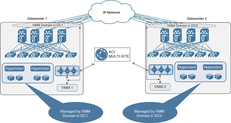
Figure 6-13 Multiple VMM Domains Across Multiple Sites
The VMM at each site manages the local hosts and peers with the local APIC domain to create a local VMM domain. This model is supported by all the VMM options supported by Cisco ACI: VMware vCenter Server, Microsoft SCVMM, and OpenStack controller.
The configuration of the VMM domains is performed at the local APIC level. The created VMM domains can then be imported into the Cisco ACI multi-site policy manager and associated with the EPG specified in the centrally created templates. If, for example, EPG 1 is created at the multi-site level, it can then be associated with VMM domain DC 1 and with VMM domain DC 2 before the policy is pushed to Sites 1 and 2 for local implementation.
The creation of separate VMM domains across sites usually restricts the mobility of virtual machines across sites to cold migration scenarios. However, in specific designs using VMware vSphere 6.0 and later, you can perform hot migration between clusters of hypervisors managed by separate vCenter servers. Figure 6-14 and the list that follows demonstrate and describe the steps required to create such a configuration.
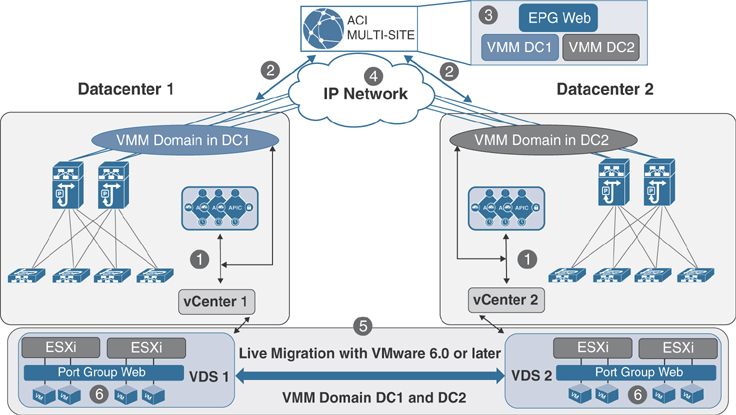
Figure 6-14 Live Migrations Across VMM Domains with vCenter 6.0 and Later
Note
At this writing, vCenter Server Release 6.0 or later is the only VMM option that allows live migration across separate Cisco ACI fabrics. With other VMMs (such as vCenter releases earlier than 6.0, SCVMM, and OpenStack deployments), if you want to perform live migration, you must deploy the VMMs in a single Cisco ACI fabric (single pod or multi-pod). Please check Cisco.com for the latest updates.
Step 1. Create a VMM domain in each fabric by peering the local vCenter server and the APIC. This peering results in the creation of local vSphere distributed switches (VDS 1 at Site 1 and VDS 2 at Site 2) in the ESXi clusters.
Step 2. Expose the created VMM domains to the Cisco ACI multi-site policy manager.
Step 3. Define a new Web EPG in a template associated with both Sites 1 and 2. The EPG is mapped to a corresponding Web bridge domain, which must be configured as stretched with flooding across sites enabled. At each site, the EPG then is associated with the previously created local VMM domain.
Step 4. Push the template policy Sites 1 and 2.
Step 5. Create the EPGs in each fabric, and because they are associated with VMM domains, each APIC communicates with the local vCenter server, which pushes an associated Web port group to each VDS.
Step 6. Connect the Web virtual machines to the newly created Web port groups. At this point, live migration can be performed across sites.
Single Virtual Machine Manager Across Sites
Figure 6-15 depicts the scenario in which a single VMM domain is used across sites.

Figure 6-15 Single VMM Domain Managing VMs Across Multiple Sites
In this scenario, a VMM is deployed in Site 1 but manages a cluster of hypervisors deployed within the same fabric and also in separate fabrics. Note that this configuration still leads to the creation of different VMM domains in each fabric, and different VDSs are pushed to the ESXi hosts that are locally deployed. This scenario essentially raises the same issues as discussed in the previous section about the support for cold and hot migration of virtual machines across fabrics.
Remote Leaf
ACI fabric allows for integration with multiple VMM domains. With this integration, the APIC pushes the ACI policy configuration—such as networking, telemetry monitoring, and troubleshooting—to switches based on the locations of virtual instances. The APIC can push the ACI policy in the same way as a local leaf. A single VMM domain can be created for compute resources connected to both the ACI main DC pod and remote leaf switches. VMM/APIC integration is also used to push a VDS to hosts managed by the VMM and to dynamically create port groups as a result of the creation of EPGs and their association to the VMM domain. This allows you to enable mobility (“live” or “cold”) for virtual endpoints across different compute hypervisors.
Note
It is worth noting that mobility for virtual endpoints can also be supported if a VMM domain is not created (that is, if VMs are treated as physical resources).
Virtual instances in the same EPG or Layer 2 domain (VLAN) can be behind the local leaf as well as the remote leaf. When a virtual instance moves from the remote leaf to the local leaf or vice versa, the APIC detects the leaf switches where virtual instances are moved and pushes the associated policies to new leafs. All VMM and container domain integration supported for local leafs is supported for remotes leaf as well.
Figure 6-16 shows the process of vMotion with the ACI fabric.

Figure 6-16 vMotion Between Remote Leaf to ACI Fabric in the Main Data Center
The following events happen during a vMotion event:
Step 1. The VM has IP address 10.10.10.100 and is part of the Web EPG and the Web bridge domain with subnet 10.10.10.1/24. When the VM comes up, the ACI fabric programs the encapsulation VLAN (vlan-100) and the switch virtual interface (SVI), which is the default gateway of the VM on the leaf switches where the VM is connected. The APIC pushes the contract and other associated policies based on the location of the VM.
Step 2. When the VM moves from a remote leaf to a local leaf, the ACI detects the location of the VM through the VMM integration.
Step 3. Depending on the EPG-specific configuration, the APIC may need to push the ACI policy on the leaf for successful VM mobility, or a policy may already exist on the destination leaf.
Summary
Integrating the virtual compute platform into ACI extends the policy model down and provides deep visibility into the virtualization layer. As discussed in this chapter, due to the open architecture of Cisco ACI, any hypervisor or container-based platform vendor—such as VMware, Microsoft, OpenStack, Kubernetes, or OpenShift—can be integrated into ACI.
In a single ACI fabric located at a single site or stretched between multiple sites using transit leaf, multi-pod, or remote leaf, individual VMM integration can be leveraged using the same policy model in any of the locations where the ACI fabric is stretched because a single control and data plane has been stretched between multiple data center locations. In a dual ACI fabric or multi-site environment, separate APIC clusters are deployed in each location; therefore, a separate VMM domain is created for each site.
Note
There are no Key Topics or Review Questions for this chapter.