
Chapter 9
Monitoring ACI Fabric
In this chapter, you will learn about how proper monitoring solutions can enable businesses to run their network operations smoothly. Network monitoring can help companies minimize service downtime and get immediate return on investment on their software-defined application-hosting network infrastructure, such as Cisco ACI. The following topics related to monitoring ACI are covered in this chapter:
ACI internal monitoring tools (including SNMP, syslog, and NetFlow)
ACI external monitoring tools (including Network Insights, Network Assurance Engine, and Tetration)
Importance of Monitoring
Today’s businesses are highly dependent on applications that must be deployed on a network at a fast pace. This shift in doing business gave birth to software-defined networking, thus providing application agility. Many applications need to be up and running all the time, with minimal service disruptions for business continuity.
Another challenge is network scalability. With the adoption of virtualization techniques and an increase in the number of endpoints on IP networks, companies need to have highly scalable and continuously changing network infrastructure. Network monitoring is therefore necessary for a business to run smoothly and successfully. The main objective of monitoring the network is to constantly analyze system failures, network performance, and security threats and get automatic alerts before any real service outage occurs.
A great deal of IT time (up to 42%, according to Sirkin Research report in 2019) is spent in troubleshooting issues across the entire network. In addition, it’s often very hard to reproduce issues; therefore, it is very hard to conclude root cause analyses (RCAs). Spending extra time troubleshooting the network extends service outage periods and leads to business loss and sometimes even complete business meltdowns. The problem is that IT teams often take reactive rather than proactive approaches. For example, when it comes to system failures, network administrators tend to jump straight to troubleshooting the issue. For issues related to change management, they might quickly undo the change to bring the service back to operational state. In the event of security breaches, network administrators often scramble to prevent risk. When it comes to compliance, they might dig into the audit logs. Thus, all their actions are reactionary. Proactively taking the appropriate measures can be much more effective. Proactive monitoring is an important piece of a network administrator’s job. However, it is often neglected because solving critical issues in the network usually takes priority, and proactive monitoring tasks languish on the back burner.
Proactively monitoring your network infrastructure provides the following benefits:
Staying ahead of outages: Having a proper monitoring solution helps keep you ahead of the game and prevents outages. Monitoring can give you a complete view of your network that will help you fix issues fast during troubleshooting and reduce service downtime.
Easing management in large and changing networks: Software-defined networking infrastructure such as Cisco ACI provides scalability and flexibility to constantly make changes on the fly. With a proper monitoring solution in place, you can easily achieve these goals without disrupting service. Also, continuously making successful changes in the network builds trust within management, and getting maintenance window approval in the data center becomes much easier.
Identifying security threats: One of the most important tasks of a network administrator is to keep the company’s data secure. Network monitoring provides information about security breaches and anomalies happening in the network that might potentially compromise the company’s confidential data.
Achieving service-level agreements (SLAs): Keeping network operations up and running all the time helps you achieve SLAs with your end users and builds trust.
Providing immediate return on investment (ROI): With increased service uptime, you more quickly realize ROI on the application-hosting infrastructure that is running your business.
Cisco ACI is a policy-driven object-oriented infrastructure that is managed by a centralized controller called the Cisco Application Policy Infrastructure Controller (APIC). The fabric infrastructure configuration and statistics are stored on an APIC rather than on each individual network device. This forces network administrators to adapt to a new way of managing, monitoring, and troubleshooting their infrastructure and makes it easier to deal with new technologies introduced in the industry.
Faults and Health Scores
Faults and health scores are key components of ACI monitoring, and it is critical to understand these concepts and their importance for smooth operation of your fabric.
Faults
As you have learned in this book, ACI is deployed and managed using a policy-based object model. In this policy-based model, the APIC not only provisions the entire network infrastructure but also provides centralized storage for all telemetry data, including faults, events, statistics reported by the fabric switches, virtual switches, and integrated L4/L7 devices. Much as configurations are stored as managed objects in ACI, faults, events, and statistics are also represented as a collection of managed object in the management information tree (MIT). All objects in ACI can be queried, including faults. In this policy model, a fault is represented as a mutable, stateful, and persistent managed object (MO) of class faultInst or faultDelegate.
When a specific condition occurs, such as a component failure or an alarm, the system creates a fault as a child object to the MO that is primarily associated with the fault. For a fault object class, the fault conditions are defined by the fault rules of the parent object class. Fault MOs are similar to other MOs in the MIT, as they have a parent, a distinguished name (DN), a relative name (RN), and so on. The fault code is an alphanumerical string in the form FXXX that uniquely identifies the type of fault being raised.
A fault is visible only if it affects an object in the MIT. The lower an object in the tree, the more specific the faults are to the object’s failure. System faults list all the faults in the ACI fabric. In most cases, a fault MO is automatically created, escalated, de-escalated, and deleted by the system as specific conditions are detected. There can be at most one fault with a given code under a managed object. If the same condition is detected multiple times while the corresponding fault MO is active, no additional instances of the fault MO are created. In other words, if the same condition is detected multiple times for the same affected object, only one fault is raised, and a counter for the recurrence of that fault is incremented.
Faults are triggered based on fault rules, counters crossing thresholds, task/state failures, and object resolution failures. A fault is always raised on the node where the condition was detected (either a fabric node or controller). Users are not allowed to define new faults.
As illustrated in Figure 9-1, in ACI, faults go through a life-cycle process to avoid false positives. In that process, when a fault is generated due to a failure event, the system detects the fault, adds the fault object in the MIT, and goes into soaking state. When the soaking timer expires (the default is 120 seconds) and the target severity is reached, the fault transitions to a raised state. It retains the fault in this state until the error is resolved automatically by the system or by the network operator. Once the error is resolved, the system detects that and goes into clearing state. When the clearing timer expires (the default is 120 seconds), the system clears the fault. However, it still keeps the fault in the system until the retention timer expires (the default is 3600 seconds), and finally the fault is removed from the system completely. These timers are configurable within the range from 0 to 3600 seconds for the soaking and clearing intervals and from 0 to 31,536,000 seconds for the retention interval.
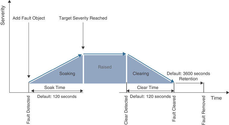
Figure 9-1 Fault Life Cycle
The fault severity provides an indication of the estimated impact on the system and its capability to provide further service. Some of the severity values are as follows:
Warning (potential issue but possibly no immediate impact to the system)
Minor
Major
Critical (system or component completely unusable)
Let’s look at some useful NX-OS CLI commands for viewing system faults.
To view all system faults, use this command:
apic1# show faults details
Example 9-1 shows some specific subcommands for querying system faults.
Example 9-1 show faults Subcommands
apic1# show faults ?
 ack           Acknowledgment status
 cause         Cause
 code          Fault code
 controller    Show controller information
 detail        Detailed faults information
 end-time      Fault activity in time interval
 history       Historical information
 id            Fault ID
 l4l7-cluster  Show L4 L7 Device information
 l4l7-graph    Show L4 L7 Graph information
 last-days     Fault activity in time interval
 last-hours    Fault activity in time interval
 last-minutes  Fault activity in time interval
 lc            Lifecycle state
 leaf          Show command for leaf
 microsoft     Show Microsoft information
 min-severity  Minimum severity
 quota         Show Quotas Information
 redhat        Show Redhat information
 severity      Severity
 spine         Show command for spine
 start-time    Fault activity in time interval
 tenant        Show Tenants Information
 type          Type
 vmware        Show VMware information
Also, you can query faults raised on fabric nodes through the REST API. Example 9-2 shows a REST query to fabric leaf node 201 that returns the fault with code F1543, along with details about the fault, such as fabric status inactive, Node 201 inactive and not reachable, and severity critical.
Example 9-2 REST Query to Check Faults
GET :  https://apic-hostname-or-IP/api/node/mo/topology/pod-1/node-201.json?query-
  target=self&rsp-subtree-include=faults
{
    "totalCount": "1",
    "imdata": [
        {
            "fabricNode": {
                "attributes": {
                    "adSt": "off",
                    "annotation": "",
                    "childAction": "",
                    "delayedHeartbeat": "no",
                    "dn": "topology/pod-1/node-201",
                    "extMngdBy": "",
                    "fabricSt": "inactive",
                    "id": "201",
                    "lastStateModTs": "2019-11-05T16:50:07.568-05:00",
                    "lcOwn": "local",
                    "modTs": "2019-11-05T16:50:21.889-05:00",
                    "model": "N9K-C93180LC-EX",
                    "monPolDn": "uni/fabric/monfab-default",
                    "name": "leaf-201",
                    "nameAlias": "",
                    "nodeType": "unspecified",
                    "role": "leaf",
                    "serial": "FDO212225QJ",
                    "status": "",
                    "uid": "0",
                    "vendor": "Cisco Systems, Inc",
                    "version": ""
                },
                "children": [
                    {
                        "faultInst": {
                            "attributes": {
                                "ack": "no",
                                "cause": "node-inactive",
                                "changeSet": "",
                                "childAction": "",
                                "code": "F1543",
                                "created": "2020-01-18T08:26:59.968-05:00",
                                "delegated": "no",
                                "descr": "Node 201 is inactive and not reachable.",
                                "domain": "infra",
                                "highestSeverity": "critical",
                                "lastTransition": "2020-01-18T08:29:13.714-05:00",
                                "lc": "raised",
                                "occur": "1",
                                "origSeverity": "critical",
                                "prevSeverity": "critical",
                                "rn": "fault-F1543",
                                "rule": "fabric-node-inactive",
                                "severity": "critical",
                                "status": "",
                                "subject": "fabric-node-inactive",
                                "type": "environmental"
                            }
                        }
                    }
                ]
            }
        }
    ]
}
Health Scores
Network operations teams are constantly asked to answer basic questions regarding the current status, performance, and availability of the networks they are operating. Answering such questions might be easy as they often relate to independent devices or links. However, this information by itself is of little to no value without additional data on the overall health of the network. Manually collecting and correlating information about the entire network is a time-consuming and laborious task. In the past, network operators had to search for the right tool to provide a model of the infrastructure that described the relationship between the various devices and links. ACI automates data collection and correlation of information about the network and provides a health score based on data collected, computed, and correlated throughout the fabric in real time.
The single consolidated health score shows the current status of all the objects in the network, including links and devices, their relationships, the real-time status of their utilization, and a quick at-a-glance assessment of the current status of the entire system. This visibility has a number of practical use cases, and later in this chapter we will classify these use cases as proactive or reactive. ACI also provides the flexibility to monitor some aspects of how the health score is calculated and how various faults impact the calculation of the health score. The health score ranges from 0 to 100%, with 100% indicating a fully fit and functional ACI fabric. Ideally, the health of all application and infrastructure components should always be 100%. However, this is not always realistic, given the dynamic nature of data center environments. Links, equipment, and endpoints experience failures. The health score should be seen as a metric that changes over time, and the goal should be to increase the average health score of a given set of components over time. Furthermore, a decrease in the health score does not always necessarily mean there is an issue in the network. For example, say that you have been given a task to preprovision all the ToR leaf ports and map them to EPGs. However, no application server has been physically connected to these ports. In this case, ACI generates faults, and the health score decreases, but in reality, this is a predetermined reduction in the health score based on decisions by the fabric administrator.
The majority of objects in ACI have associated health scores, which can be found in the APIC GUI’s System Dashboard tab or the Policy tab for an object. To check the overall fabric health in the APIC GUI, go to System > Dashboard. In this tab, you can view the APIC, node (leaf/spine), and tenant health scores that are less than 99%. You can also examine a graph depicting the health score of the system over a period of time. The health graph provides a good indication of any system issues. If the system is stable, the graph shows a constant value; otherwise, it fluctuates.
The health score is corelated to faults. A fault generated in the system reduces the health score. On the other hand, remediating a fault normalizes the health score. All health scores are instantiated from the healthInst class in the MIT and can be extracted through the REST API. System and pod health scores are calculated based on average weighted health scores of leafs, spines, and the number of endpoints in the fabric. Similarly, tenant health scores are calculated based on logical components contained in each tenant. From a fabric administration perspective, there is no need to know the formula by which health score are calculated because the system automatically does the calculations. Basically, health scores are directly linked with faults associated to a managed object. Each fault is weighted based on the fault’s severity level. For example, a critical fault might weigh 100%, whereas a warning might weigh only 20%.
Almost every object has a Health tab. For example, to check whether a specific EPG has faults, in the APIC GUI, you can go to Tenants > Application Profile > EPG. On the right-hand side of the work pane, look for the Health tab. You can also access the Health tab under History > Health. This tab shows information on the affected object and how it is tied within the larger model. By clicking on the health score, you can explore the health tree of any affected object or policy to reveal the faults (see Figure 9-2).

Figure 9-2 Navigating the Health Score of an Object
Let’s look at some useful NX-OS CLI commands to view the health of specific objects.
To view the health of a tenant, enter the following command:
apic1# show health tenant tenant-name
To view the health of a bridge domain within a tenant, enter the following command:
apic1# show health tenant tenant-name bridge domain bd-name
To view the health of an endpoint group of an application within a tenant, enter the following command:
apic1# show health tenant tenant-name application app-name epg
epg-name
To view the health of a leaf, enter the following command:
apic1# show health leaf node-ID
Also, you can query health scores through the REST API. The following example is a REST query to the fabric that returns the health score for a tenant named t01:
GET :  https://apic-hostname-or-IP/api/node/mo/uni/
tn-t01.json?query-target=self&rsp-subtree-include=health
As mentioned earlier, there is really no need to understand the calculations of the health scores as ACI does them for you, but you do need to have a basic understanding of whether faults should have high, medium, low, or “none” fault levels. Although faults in ACI are initially set at default values, it is possible to change these values to better match your environment. Keep in mind that because of role-based access control, not all administrators can see all of the health scores. For example, a fabric administrator can see all health scores, but tenant administrators can only see the health scores that pertain to the tenants to which they have access.
The following sections dive into some proactive and reactive health score use cases.
Health Score Used in Proactive Monitoring
Health scores identify faults, and they essentially provide baselines to which you can make comparisons of your system later. If you see that a leaf switch is at 100% one week, and the next week the leaf is showing a warning, you can drill down to see what has changed. In such a scenario, it is possible that the links might be oversubscribed; hence, it could be time to either move some of the workload to another leaf or to add more bandwidth by connecting more cables. When you are facing only a warning, you have time to resolve the issue before any bottleneck on the network is noticeable.
Health scores can be used to proactively monitor your ACI environment in a number of other ways, such as providing visibility of certain components to other groups in your company. Because you can export health scores and faults, it is possible to send notifications to application owners, VMware administrators, database administrators, and so on to provide monitoring of the environment across the entire network that has not previously been easily available.
Health Score Used in Reactive Monitoring
Health scores can provide assistance in diagnosing problems and resolving immediate issues. Upon notification that a health score has been degraded, an operator can use the APIC GUI to easily navigate the relationships and faults that are contributing to the health score degradation. When the faults causing a poor health score have been identified, you can look at the faults to find information about possible remediation steps. For most objects there is a Health tab that can be used to explore the relationship between objects and their associated faults; the information on this tab could potentially help identify the root cause of the issue and provide remediation guidance.
Health Score with Interface Errors
Health scores enable you to monitor faults and the general health of your ACI fabric. However, in certain cases, such as with interface cyclic redundancy check (CRC) errors, if the interface does not flap, then no fault will be generated, and there will be no deviation in the health score result.
In order to monitor CRC errors through the health score, you need to take the following configuration steps in the APIC GUI:
Step 1. Go to Fabric > Fabric Policies > Policies > Monitoring > default > Stats Collection Policies, and on the right-hand side of the navigation pane, select Layer 1 Physical Interface Configuration from the Monitoring Object drop-down and then select Ingress Drop Packets from the Stats Type drop-down.
Step 2. Under Config Thresholds, click the + sign to open the Config Threshold window.
Step 3. Click the Edit Threshold checkbox next to Ingress Errors Drop Packets rate.
Step 4. In the Edit Stats Threshold box, modify the Rising values based on your environment and needs. Click Submit. Click Close.
Figure 9-3 illustrates these configuration steps, where the system counts the packets drop (CRC) at a five-minute interval and raises a fault when the threshold is hit. This affects the health score accordingly. In this example, if there are 5 CRC errors in a five-minute interval, a fault with severity warning is raised; if the count increases over 250, a minor fault is raised; and so on.
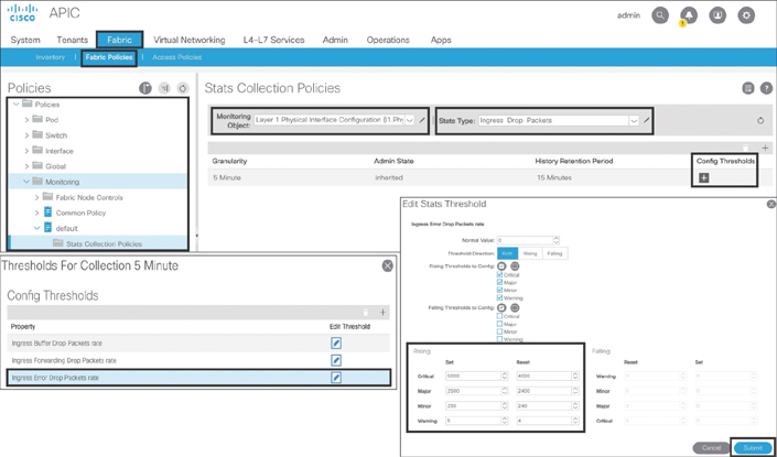
Figure 9-3 Configuring Statistics Thresholds for Monitoring CRC Errors
ACI Internal Monitoring Tools
ACI offers some monitoring tools and protocols out of the box, such as SNMP, syslog, and NetFlow. These tools, which companies have been using since early in the computer networking era, are part of the ACI software, but you need to enable and configure the necessary parameters before you can use them.
Note
Chapter 10, “Network Management and Monitoring Configuration,” provides detailed configuration steps for SNMP, syslog, and NetFlow.
SNMP
Simple Network Management Protocol (SNMP), which has been in use for decades, is a mechanism for managing and monitoring network devices. SNMP runs on the UDP protocol with port numbers 161 and 162. SNMP works in both push and pull models. When you run an SNMP query against a network device, you are pulling the stats out from the network device. In this case, SNMP uses UDP port 161. On the other hand, when an event occurs on a network device, SNMP pushes the stats toward a management station and uses UDP port 162. (This push operation is called a trap.)
SNMP has three basic components:
Managed device: The hardware device to be monitored
Agent: The SNMP daemon running on the managed device
Network management system: The monitoring system that enables the SNMP client to communicate with the agent running on the managed device
SNMP is supported on a wide range of networking devices, and you need to enable and configure an agent to be able to communicate to a network management system (NMS). The agent maintains an information database that describes the network parameters of a managed device. The network management system refers to this database to ask the agent for specific information and further translates it as needed. This commonly shared information database between the agent and the network management system is called the Management Information Base (MIB). This is similar to the ACI concept in which a configuration and its statistical data are stored as an object, and the objects are organized in a hierarchical fashion under the MIT. SNMP also stores the information as an object with an object ID (OID), and these objects are organized in a hierarchy under the MIB.
For example, Figure 9-4 shows that .1.3.6.1.2.1.1.1 is the OID for the system description sysDescr for a network device.
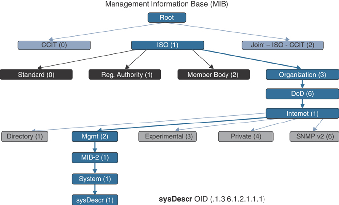
Figure 9-4 SNMP MIB Hierarchy for the sysDescr OID
Over time, SNMP has evolved into various versions (v1, v2c, and v3) for additional functionality but mainly focuses on security enhancements.
SNMP uses some of the following basic commands:
GET: A request sent by the management system to the managed device. It is performed to pull one or more values from the managed device.
GET NEXT: A similar operation to GET. The major difference is that the GET NEXT command retrieves the value of the next OID in the MIB.
GET BULK: Used to retrieve a large volume of data from the MIB.
SET: An operation used to modify or assign the value of a managed device.
TRAPS: A command initiated by an agent (unlike the preceding SNMP operational commands, which are executed from the management system), which is a signal to the management system when an event occurs on the managed device.
INFORM: A command initiated by an agent that includes confirmation from the management system on receiving the message.
RESPONSE: A command used to carry back the value(s) or signal of actions directed by the management system.
Since ACI Release 1.2(1), SNMP has been supported on both the APIC and the switches (leafs/spines) of the ACI fabric. In ACI, SNMP agents run independently on the APIC and on switches, providing separate network statistics to the management station. ACI supports numerous SNMP MIBs on switches. However, only a subset of SNMP MIBs are available on the APICs.
Table 9-1 outlines the SNMP-supported MIBs and TRAPs.
Table 9-1 SNMP MIB and Traps Supported in ACI
MIBs |
Traps |
System |
coldstart |
Cisco-IF-Extension-MIB |
cefcFRUInserted, cefcFRURemoved |
Entity-MIB |
cefcFanTrayStatusChange, cefcModuleStatusChange |
Cisco-Entity-FRU-Control-MIB |
entSensorThresholdNotification |
Cisco-Entity-Sensor-MIB |
cefcPowerStatusChange |
Cisco Process MIB |
cpmCPURisingThreshold, cpmCPUFallingThreshold |
IF-MIB |
ospfIfStateChange, ospfNbrStateChange |
OSPF v2, OSPFv3 |
cieLinkUp, cieLinkDown (though only on downlink host ports) |
BGP |
|
Cisco-BGP |
|
Cisco-IETF-ISIS |
|
Cisco-BFD-MIB |
Note
For the latest SNMP MIB and TRAP support in ACI, see Cisco.com.
All SNMP protocol versions (v1, v2c, and v3) are supported in ACI. SNMP in ACI can only perform GET, GET NEXT, GET BULK, and WALK operations. SNMP write queries using the SET command are not allowed. As you have already learned, ACI only allows the APIC to make configuration changes through REST APIs. ACI also supports SNMP traps, but only 10 traps destination management stations can be used in a configuration. SNMP traps is enabled based on policy configuration in the Access, Fabric, and Tenant tabs in the APIC GUI. SNMP traps are generated based on the events or faults that occurred on a managed object. On the APIC, a managed object is translated to an SNMP object. SNMP in ACI requires an explicit “out-of-band (OOB) contract” on the APIC by permitting the SNMP port (UDP port 161); otherwise, SNMP packets are dropped.
The SNMPd daemon running on an APIC has two components:
Agent: The SNMP agent is an open-source net-snmp agent (version: 5.7.6). The SNMP agent handles SNMP sessions from the SNMP clients and also handles the SNMP protocol processing.
DME: The SNMP Data Management Engine (DME) handles the MIT interface to read the MOs and translate the information into the SNMP object format.
Interface Failures Example
Let’s consider an example of shutting down an interface of a leaf with OOB address (10.88.196.130). In this example, interface Eth1/30 is shut down. An SNMP trap is sent out to the destination IP address of the management station (10.88.146.197). The SNMP OID value included in the trap is .1.3.6.1.4.1.9.9.276.0.1. You can use the following URL to browse the OID details:
https://snmp.cloudapps.cisco.com/Support/SNMP/do/BrowseOID.do?local=en
Figure 9-5 illustrates the interface down SNMP trap.
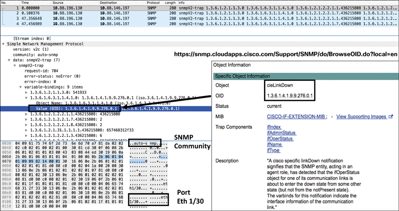
Figure 9-5 Server Interface Down SNMP Trap
When you bring up the interface, another SNMP trap is sent out to the management station with a different OID value (.1.3.6.1.4.1.9.9.276.0.2), as shown in Figure 9-6.

Figure 9-6 Server Interface Up SNMP Trap
Let’s consider another example of interface failure. In this case, let’s say the interfaces are bundled with a virtual port channel (VPC). In this example, VPC 2 is shut down. An SNMP trap is sent out to the destination IP address of the management station (10.88.146.197). The OID included in the trap is (.1.3.6.1.2.1.2.2.1.8). You can use the following URL to browse the OID details:
https://snmp.cloudapps.cisco.com/Support/SNMP/do/BrowseOID.do?local=en
As shown in Figure 9-7, the value of the first OID (1.3.6.1.2.1.2.2.1.8) in the SNMP trap is 2, which indicates “down” according to the IF-MIB details. The next OID (1.3.6.1.2.1.31.1.1.1.1) in the SNMP trap is the hex value 706f32, which converts to the ASCII value Po2. The third OID (1.3.6.1.2.1.2.2.1.3) in the SNMP trap shows the value 53, which is propVirtual according to the IF-MIB details and tells you that VPC 2 is down. Similarly, when the VPC comes back online, another SNMP trap with the same OID (1.3.6.1.2.1.2.2.1.8) shows the value 1, which is up according to the IF-MIB details.

Figure 9-7 Server VPC Interface Down/Up SNMP Traps
Syslog
Syslog makes it possible to collect and store system logs (faults, events, audits, and sessions) of network devices either locally or to an external host running a syslog process. It runs on the UDP protocol with port 514. Faults or events in the ACI fabric can trigger the sending of a syslog message. Fault-generated system messages are triggered by a fault rule, a threshold crossing, or a failure of a task or finite state machine (FSM) sequence. Event-generated system messages are triggered by an event rule or an event in NX-OS on a leaf or the spine. Not all syslog messages indicate problems. Some of them are informational, and others help in diagnosing an issue during a troubleshooting session.
The syslog message structure in ACI is as follows:
timestamp host %LOG_LOCAL(1-7)-severity-SYSTEM_MSG [code][lifecycle
state][rule][severity text] [DN of affected MO] Message-text
The following is an example of a fault-related syslog message:
Apr 10 12:28:21 apic1 %LOG_LOCAL7-2-SYSTEM_MSG [F0321][soaking]
[unhealthy][critical][topology/pod-1/ node-1/av/node-1/fault-F0321]
Controller 1 is unhealthy because: Data Layer Partially Degraded
This system message conveys the following information:
The timestamp of the message is Apr 10 12:28:21.
apic1 is the host and indicates that this message is generated by the controller.
2 (Major) is the severity level and indicates a critical condition.
F0321 is the fault code, which is fltInfraWiNodeHealth.
soaking is the current fault life cycle state.
unhealthy is the cause of the fault.
critical is the fault severity.
topology/pod-1/node-1/av/node-1 is the DN of the affected MO, which is Node 1 in Pod 1.
fault-F0321 is the fault object.
The message text is Controller 1 is unhealthy because: Data Layer Partially Degraded.
The following is an event-related syslog message:
Apr 10 02:18:16 leaf1 %LOG_LOCAL7-6-SYSTEM_MSG [E4205126][port-down]
[info][sys/phys-[eth1/3]/phys] Port is down. Reason: adminCfgChng
This system message conveys the following information:
The timestamp of the message is Apr 10 02:18:16
leaf1 is the host, which generated this message.
6 (Info) is the severity level and indicates an informational condition.
E4205126 is the event code.
port-down is the cause of the event.
info is the fault severity.
sys/phys-[eth1/3]/phys is the DN of the affected MO.
The message text is Port is down. Reason: adminCfgChng.
The syslog severity level is a single-digit code that reflects various severity conditions. The lower the severity level of the system message, the more serious the condition of the system. Unlike NX-OS, ACI follows the International Telecommunication Union (ITU) standards for syslog severity levels described in RFC 5674. Table 9-2 maps the severity levels of system messages between NX-OS and ACI.
Table 9-2 Syslog Severity Levels
Severity Level (NX-OS) |
ITU Level (ACI) |
Description |
|
0 |
Emergency |
— |
System is unusable |
1 |
Alert |
Critical |
Immediate action required |
2 |
Critical |
Major |
Critical condition |
3 |
Error |
Minor |
Error condition |
4 |
Warning |
Warning |
Warning condition |
5 |
Notification |
Cleared |
Normal but significant condition |
6 |
Informational |
Info |
Informational messages only |
7 |
Debugging |
— |
Messages that appear during debugging only |
Table 9-3 lists some of the system messages that are critical enough to generate alerts and trouble tickets.
Table 9-3 Critical System Messages
Fault Number |
Fault Object Name |
Description |
F1543 |
fltFabricNodeInactive |
Fabric node is unreachable |
F0532 |
fltEthpmIfPortDownInfraEpg |
Host interface is down and is in use by the EPG |
F1385 |
fltOspfAdjEpFailed |
OSPF adjacency is down |
F0299 |
fltBgpPeerEntryFailed |
BGP peer is not established |
F1296 |
fltVpcIfIfDown |
VPC interface is down, and peer interface is down as well |
F2705 |
fltVpcIfIfImpaired |
VPC interface is down, and peer interface is up |
F1262 |
fltInfraServiceOptimalLeadership |
APIC reports that some services do not have ideal replica leaders of shards |
F0321 |
fltInfraWiNodeHealth |
APIC reports that the distributed internal database (data layer) of the controller cluster is not fully functional |
F1394 |
fltEthpmIfPortDownFabric |
Fabric port is down |
F0475 |
fltTunnelIfDestUnreach |
Tunnel destination is unreachable |
F0360 |
fltIsisFmcastTreeTreeInactive |
Operational state of an Mcast tree changes to inactive in the fabric |
F1360 |
fltCoopAdjEpCoopAdjEpDown |
Coop adjacency is down |
F0411 |
fltEqptPsuFailed |
Power supply unit is failed in the fabric node |
F0412 |
fltEqptPsuFanFailed |
Power supply unit fan is failed in the fabric node |
F0413 |
fltEqptPsuSlotPsuMissing |
Power supply unit is missing/removed from the fabric node |
F1317 |
fltEqptPsgPNonRedun |
Power supply unit is nonredundant in the fabric node |
F1318 |
fltEqptPsgPZeroPwr |
Power supply unit is not detected correctly in the fabric node |
F1321 |
fltEqptFtFanTrayFailed |
Fan tray failed in the spine (Nexus 9500) |
F1322 |
fltEqptFanFanFailed |
Fan failed in the spine (Nexus 9500) |
F1323 |
fltEqptFtSlotFanTrayMissing |
Fan tray is missing/removed from the spine (Nexus 9500) |
F1451 |
fltEqptPsuShut |
No power in the power supply unit |
F1526 |
fltEqptSlotFailed |
Fabric module or line card failed in the spine (Nexus 9500) |
F0101 |
fltEqptStorageFailed |
Storage device on the APIC failed |
F2992 |
fltSvcredirRsDestAttOperStFailed |
PBR service destination goes to failed state |
Note
For a complete and up-to-date list of all system messages for the ACI code you are running on your network, see Cisco.com.
Example: Leaf Membership Failure
Let’s consider an example of a leaf node, Node 201, with an OOB management address (10.88.196.108) becoming unreachable by the APIC cluster due to a problem (likely due to fabric link, transceiver, or LLDP failure). A syslog message is generated as a fault with fault ID F1543. The incident went through the fault life cycle and now is in a raised state with a critical severity level. The system message states that Node 201 is inactive and not reachable, as shown in Figure 9-8.

Figure 9-8 Fabric Node Unreachable System Message
Example: Spine/IPN Failure
Say that you have recently extended your single-pod ACI fabric to multiple pods for leaf scalability. Multi-pod requires an interpod network (IPN) to provide connectivity between multiple pods. This communication channel is established by connecting spines in each pod to IPN routers. Because an IPN glues together multiple pods in a single fabric, it is important to have proper network resiliency and proactive monitoring for this transport medium to ensure smooth operation of your application-hosting infrastructure hosted between multiple pods.
Figure 9-9 shows a sample multi-pod topology.

Figure 9-9 Sample Multi-pod Topology for Monitoring
The sample topology shown in Figure 9-9 has only one IPN router, which is not a best practice. The goal with this sample topology is to simplify the message and help you develop a proactive monitoring and alerting mechanism for your IPN. Say that you notice that the link from Spine203 loses connectivity to the IPN router and knocks off Pod 2 and its associated ACI fabric infrastructure, as shown in Figure 9-10.

Figure 9-10 Spine/IPN Link Failure in Multi-pod
You have configured syslog data collectors to send system logs to an external syslog server. However, in order to forward these logs to an external server, you need to enable the syslog source in tenant, fabric, and access policies and associate it with the syslog destination—the external server. The spine/IPN connectivity is configured in the Infra tenant, and so it is important to define the syslog sources in the Infra tenant. (Chapter 10 describes the configuration of syslog and other monitoring and management protocol and tools.)
After losing the link between Spine203 and the IPN router, as shown in Figure 9-10, you start receiving the logs. These are critical logs that you should proactively monitor and generate trouble tickets against to remediate the issue rapidly.
First, the OSPF adjacency between Spine203 and the IPN went down. ACI Spine203 in Pod 2 generates the following log:
Feb 18 14:26:30 s1-pod2-spine203 %LOG_LOCAL7-6-SYSTEM_MSG [F1385]
[deleted][protocol-ospf-adjacency-down][cleared][sys/ospf/inst-default/
dom-overlay-1/if-[eth1/1.1]/adj-1.1.1.1/fault-F1385] OSPF adjacency is
not full
The IPN router generates the same OSPF adjacency down state log:
2020 Feb 18 14:26:29.869 IPN %ETHPORT-5-IF_DOWN: Interface
Ethernet1/9.4 is down
2020 Feb 18 14:26:29.274 IPN %OSPF-5-ADJCHANGE:  ospf-aci [31054]  Nbr
10.255.5.9 on Ethernet1/9.4 went DOWN
Second, the tunnel interfaces go down from Spine203 in Pod 2 to Spine201 and Spine202 in Pod 1:
Feb 18 14:26:30 s1-pod2-spine203 %LOG_LOCAL7-3-SYSTEM_MSG [F0475]
[soaking][interface-tunnel-down][major][sys/tunnel-[tunnel1]/
fault-F0475] Tunnel destination to ip: 10.0.0.33/32 for tunnel1 is
not reachable.

Feb 18 14:26:30 s1-pod2-spine203 %LOG_LOCAL7-6-SYSTEM_MSG [E4208070]
[oper-state-change][info][sys/tunnel-[tunnel1]] Interface tunnel1 is
down reason Destination unreachable

Feb 18 14:26:30 s1-pod2-spine203 %LOG_LOCAL7-3-SYSTEM_MSG [F0475]
[soaking][interface-tunnel-down][major][sys/tunnel-[tunnel2]/
fault-F0475] Tunnel destination to ip: 10.0.0.34/32 for tunnel2 is
not reachable.

Feb 18 14:26:30 s1-pod2-spine203 %LOG_LOCAL7-6-SYSTEM_MSG [E4208070]
[oper-state-change][info][sys/tunnel-[tunnel2]] Interface tunnel2 is
down reason Destination unreachable

Feb 18 14:26:30 s1-pod2-spine203 %LOG_LOCAL7-3-SYSTEM_MSG [F0475]
[soaking][interface-tunnel-down][major][sys/tunnel-[tunnel3]/
fault-F0475] Tunnel destination to ip: 10.0.0.35/32 for tunnel3 is
not reachable.

Feb 18 14:26:30 s1-pod2-spine203 %LOG_LOCAL7-6-SYSTEM_MSG [E4208070]
[oper-state-change][info][sys/tunnel-[tunnel3]] Interface tunnel3 is
down reason Destination unreachable
Finally, the iBGP peer relationship goes down from Spine203 in Pod 2 to Spine201 and Spine202 in Pod 1:
Feb 18 14:26:50 s1-pod2-spine203 %LOG_LOCAL7-6-SYSTEM_MSG [E4208055]
[oper-state-change][info][sys/bgp/inst/dom-overlay-1/peer-[2.2.2.2]/
ent-[2.2.2.2]] BGP peer operational state is changed to Closing

Feb 18 14:26:53 s1-pod2-spine203 %LOG_LOCAL7-6-SYSTEM_MSG [E4208055]
[oper-state-change][info][sys/bgp/inst/dom-overlay-1/peer-[3.3.3.3]/
ent-[3.3.3.3]] BGP peer operational state is changed to Closing
NetFlow
NetFlow is a protocol that Cisco developed and introduced in the industry in the 1990s, mainly to collect IP traffic entering and leaving a router or switch interface, depending on where it was enabled. The protocol has since evolved into various versions, but the commonly used ones are v5 and v9. Other network vendors have also developed flow technologies, but NetFlow is the industry’s de facto protocol standard for network flow analysis. With NetFlow, IP flow information is collected and sent out as NetFlow records toward an analysis system called a NetFlow collector. The NetFlow collector processes the data, performs traffic analysis, and presents the information in a user-understandable format.
Many organizations use NetFlow primarily as a network monitoring tool, and others use it for network usage billing and forensics. Monitoring and analyzing flows using NetFlow provides a holistic view of the network, bandwidth utilization, traffic patterns between application users and servers, data security, and compliance, and it helps in resolving application performance issues. In addition to the many advantages NetFlow has provided to companies, there are a few drawbacks in using the protocol. One major one has to do with network devices keeping up with today’s faster interface speeds while not overloading system processing. It is really hard for a network device to capture every flow through high-speed interfaces. To deal with this shortcoming, network devices collect only sample flows, which makes it tough to provide full network visibility, as intended by network administrators. The industry is therefore adopting more efficient ways to monitor today’s complex high-speed networks through tools using telemetry data such as Network Insights and Cisco Tetration (discussed later in this chapter).
A typical NetFlow monitoring system has three main components:
Flow exporter: Aggregates packets into flow records and exports them toward one or more flow collectors.
Flow collector: Responsible for receiving, storing, and preprocessing flow data received from a flow exporter.
Application analysis system: Analyzes the received flow data in the context of intrusion detection, traffic profiling, billing, and other use cases.
Cisco ACI supports NetFlow v9. NetFlow support in ACI started with the second-generation cloud-scale platform (for leaf switches only; spines are not supported), with the following code releases:
EX leaf: Release 2.2(1)
FX leaf: Release 2.3(1)
Remote leaf: Release 4.0(1)
The Nexus 9300 platform in ACI can be configured for either NetFlow or Tetration Analytics through a hardware agent to provide flow information. NetFlow policies in ACI can be configured under the following:
Access policies (leaf downlink ports: access, VPC, and port channel)
Tenant policies (bridge domain, L3Out)
NetFlow can be enabled on a VMware vSphere Distributed Switch (VDS) if integrated with ACI. (In-band management is required.) NetFlow in ACI does not support active/inactive timers, as do NX-OS and IOS. Flow records are exported to collectors every minute. As mentioned earlier, NetFlow can be tough on resource consumption. With ACI, the filter TCAM has no labels for bridge domain or interfaces. If a NetFlow monitor is added to two bridge domains, the NetFlow monitor uses two rules for IPv4 or eight rules for IPv6. The scale is very limited with the 1K filter TCAM in the Nexus 9300 platform. Therefore, you should keep a close eye on your ACI fabric TCAM utilization when configuring NetFlow on leaf interfaces.
Example: Network Visibility on a Border Leaf
Say that your management has tasked you with ensuring visibility of network traffic entering and leaving your newly deployed ACI fabric in your company’s data center. You start researching various protocols and tools and hear that one of your best options is to enable NetFlow on your border leaf in order to monitor all the flows coming into and going out of the ACI fabric. How can you do that?
First, you have to enable the NetFlow feature on your leafs (in this case, your border leaf). Remember that in ACI you can either run NetFlow or Tetration Analytics on your Nexus 9300 leaf platforms. You can enable all your leafs with NetFlow or Tetration, or you can enable some with NetFlow and some with Tetration. However, a single leaf cannot run both features at the same time.
When configuring NetFlow in ACI, you need to follow four simple steps under Access Policies or Tenant Policies, depending on where you need to do the configuration:
Step 1. Configure the flow record using either IPv4 or IPv6. The parameters you can select are the source/destination IP address and the source/destination port.
Step 2. Configure the flow exporter by providing the IP address of your NetFlow Analyzer machine.
Step 3. Configure the flow monitor by combining the flow record and flow exporter.
Step 4. Attach the flow monitor to the leaf interface that you intend to use to collect NetFlow information.
Note
Chapter 10 provides details on NetFlow configuration.
After configuring NetFlow on your border leaf, you start receiving network flows. You can view NetFlow information on your border leaf by using the CLI command shown in Figure 9-11. In this example, you can see that you are receiving TCP (protocol 6) and UDP (protocol 17) flows between multiple hosts with packet and byte counts.

Figure 9-11 Viewing NetFlow Information from the Border Leaf 201 CLI
To view NetFlow information in more detail, you can use the NetFlow Analyzer software of your choice. The example in Figure 9-12 shows that you are receiving NetFlow traffic on border leaf Node ID 201 with SNMP interface index IfIndex 436219904. You can run the command show interface snmp-ifindex on the leaf via the CLI, as shown in Figure 9-12, to get the actual port number, which is Eth1/4 in this case. The NetFlow Analyzer software can provide much more detailed information, such as top N applications, top N protocols, top talkers, traffic usage, and so on.

Figure 9-12 Viewing NetFlow Information in NetFlow Analyzer
Note
Figure 9-12 shows the limited free trial version of NetFlow Analyzer.
The example shown in Figure 9-13 illustrates the top conversations between hosts with source/destination IP, application, and traffic usage information.

Figure 9-13 Viewing Top Conversation
The example shown in Figure 9-14 illustrates the top N protocol information between hosts with source/destination IP, application, DSCP, and traffic usage information.
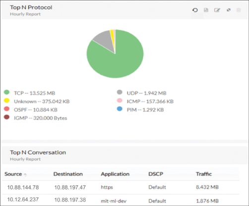
Figure 9-14 Viewing NetFlow Information in NetFlow Analyzer
ACI External Monitoring Tools
Besides internal monitoring tools and protocols that are packaged as part of ACI software, Cisco also offers external tools such as Network Insights, Network Assurance Engine, and Tetration for proactively monitoring your application-hosting infrastructure running over ACI. The following sections describe these tools.
Network Insights
Cisco Network Insights tool is for monitoring and analyzing your fabric, whether ACI fabric or a standalone VXLAN fabric running on NX-OS in real time to identify anomalies and to provide root-cause analysis and enable capacity planning. Network Insights is a suite of tools that includes Network Insights for Resources (NIR) and Network Insights Advisor (NIA). It functions by collecting and processing telemetry data and correlating it with the existing network infrastructure deployment by leveraging Cisco’s extensive knowledge and experiences from the field. Let’s dive in to each one of these tool sets.
Note
Cisco Network Insights is supported in ACI Release 4.2 and later. This book’s main focus is on ACI Release 3.2, but it also includes new features and tools in newer releases that benefit readers. Due to the great benefits and value that Network Insights provides for monitoring ACI fabric, it is included in this book.
Network Insights for Resources (NIR)
NIR is a tool that helps with troubleshooting, monitoring, auditing, and capacity planning. It is integrated as a plug-in into the Cisco ACI APIC and Data Center Network Manager (DCNM) for NX-OS support. NIR performs of the following functions:
Anomaly detection: This involves understanding the behavior of each fabric component by using different machine-learning algorithms. When the resource behavior deviates from an expected pattern, anomalies are detected and raised.
Endpoint analytics: NIR monitors the availability, location, and health of endpoints. It also analyzes the impact to these endpoints of any events or changes in the network infrastructure and helps derive potential root causes and reduce mean time to restore (MTTR).
Resource utilization: NIR offers early detection of resources that are exceeding capacity thresholds. These analytics include monitoring of software and hardware resources such as CPU, memory, and VRF instances to ensure optimal usage. NIR identifies anomalies by observing parameters such as CPU, memory, temperature, power draw, and fan speed.
Statistics: NIR monitors and detects anomalies related to interface utilization, errors, protocol stats, and state machines. It helps detect, locate, and determine root causes of issues. Correlation with endpoint analytics provides impact analysis data.
Flow analytics: NIR helps identify, locate, and analyze root causes of data path issues such as latency and packet drops for specific traffic flows.
The NIR dashboard enables quick action on specific issues that need swift attention, as shown in Figure 9-15.
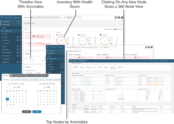
Figure 9-15 NIR Dashboard View
In this dashboard, you can use the time range and filter anomalies based on category, nodes, description, and so on for a quick run of problems you are encountering. You can also examine anomalies based on health score and top nodes with a specific timeline view.
NIR collects both software and hardware telemetry data and processes it for further analysis. For software telemetry, it provides visibility into resource utilization, environmental data, interface counters, and control plane protocol stats and events. For hardware telemetry, it provides visibility into data plane flow information and shows the flow path and statistics. You need a Cisco Services Engine (SE) appliance to store hardware flow telemetry data. For further details and the latest information, see Cisco.com.
Network Insights Advisor (NIA)
NIA is a tool that provides deployment-relevant supportability information and advisories. It is focused on actionable recommendations based on known issues and Cisco common best practices. Many people have the misconception that this tool is a replacement for Cisco Advanced Services, but it is not. NIA efficiently provides information about software caveats, security alerts, configuration best practices, and so on, enabling Cisco Advanced Services engineers to focus on design and architecture support, lab setup and build-out, knowledge transfer, and so on for their customers. NIA performs the following functions:
Advisories: NIA provides deployment-specific recommendations and best practices and upgrade impact analysis and experience.
Notices: NIA provides an inbox function, proactive end-of-life and end-of-sale announcements, new field notices, and new software maintenance updates.
Anomalies: NIA alerts users about known software defects and PSIRTs through the Anomalies Flow State Validator.
Compliance: NIA conducts system hardening checks, ensures version-specific scale limits, and provides monitoring to generate advisory.
Diagnostics: NIA offers diagnostics through Cisco TAC, cloud technical support, and Diagnostics Fast Start.
The NIA dashboard view is intended for quick action on specific issues that need swift attention, as shown in Figure 9-16.

Figure 9-16 NIA Dashboard View
The NIA dashboard provides advisories, field notices, and bugs and PSIRTs (with severity). For further details and the latest information, see Cisco.com.
Example: Application Intermittent Disconnect Issue (Standalone Compute)
Say that your application team complains of experiencing performance issues. The application is running on a standalone Linux host. The application server with IP address 10.10.10.10 was functioning normally, but for the past week or so it has gotten intermittent disconnects. You check Endpoint Tracker in the APIC and find that 10.10.10.10 is connected to Leaf 201 on interface Eth1/1, as illustrated in Figure 9-17.
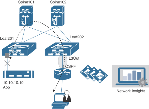
Figure 9-17 Application Intermittent Disconnect Issue (Standalone Compute)
You have NIR installed in your network. After gathering the initial data of the incident, you select the past week as the timeframe and filter the anomalies by category, nodes, and cleared in the NIR dashboard. As shown in Figure 9-18, NIR indicates that DOM and CRC errors have resulted in Layer 2 LLDP flaps and traffic disruption.
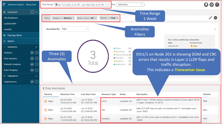
Figure 9-18 NIR Dashboard Showing Anomalies
This clearly indicates that the transceiver in interface Eth1/1 is bad. You replace the transceiver, and this fix ultimately resolves the application intermittent disconnect issue.
Example: Application Connectivity Issue (Virtual Compute)
Say that your virtualization team complains of experiencing performance issues on applications hosted on a virtual machine (VM) under VMware NSX. You have designed and implemented VMware NSX to run on top of ACI with an NSX edge gateway connected to an ACI leaf using eBGP peering. Figure 9-19 illustrates this scenario.

Figure 9-19 NIR Dashboard Showing Anomalies
NIR is deployed and running in the network, so you select the past one hour as the timeframe and filter the anomalies by category, nodes, description, and cleared. Figure 9-20 shows that BGP peer 12.37.81.3 is the NSX edge gateway connected to ACI Leaf 203 and is idle.

Figure 9-20 NIR Dashboard Showing Anomalies
You double-click on the displayed anomaly in the NIR dashboard to get more details and recommended steps to troubleshoot the issue, as shown in Figure 9-21.

Figure 9-21 NIR Dashboard Showing Anomalies
On further investigation, you find out that the NSX edge gateway VM got moved to another ESXi host connected to different leaf, which has not yet been configured for L3Out with BGP. In traditional networking without proper monitoring tools, such an issue could take hours to troubleshoot and fix.
Network Assurance Engine
With the software-defined networking (SDN) approach, adaptations have been made to address the challenges companies face in today’s fast-paced economy through rapid provisioning of hosting infrastructures at a large scale. Having layers of virtualization and switching in next-generation data center networks makes these networks complex to manage and maintain. These modern intent-based networks that are built on policies come with unique challenges.
If you make any change in your network by modifying some high-level policies, how can you guarantee that you will not break something else? Many network outages occur after configuration changes. Even if you have done all the configuration steps right, remember that your network state is changing dynamically. For example, in ACI, external prefixes are learned via border leafs. Suppose you configure a BD with a subnet that has a more specific route coming in from outside the fabric, and the configuration is causing internal application traffic to divert in different direction. Intent-based networking through programmability is an efficient way of provisioning the network, but what happens when you realize that your network doesn’t quite behave as you intended? How do you troubleshoot the network without having a complete view of the topology? Where are your VLANs, bridge domains, and endpoints sitting? How is connectivity being established between Endpoint A and Endpoint B?
To mitigate such challenges, you can use Cisco Network Assurance Engine (NAE), which provides a holistic view of your network and correlates it to the ACI policy model, helping you to troubleshoot issues rapidly. NAE encompasses everything you do in data center network operations, so when you use it, you can be confident in your changes and configurations, knowing your routing and forwarding state is consistent and ensuring that your security policies meet the segmentation goals and compliance requirements, pass audits easily, and so on. NAE brings formal verification techniques into networking, helping close the assurance gap. It mathematically verifies and validates an entire data center network for correctness, giving operators the confidence that their network is always operating consistently with their intent, even if it is dynamically changing. NAE does its magic through the methodology building blocks illustrated in Figure 9-22 and described in the list that follows.
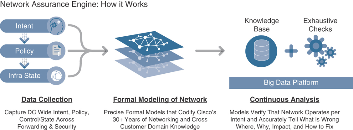
Figure 9-22 Building Blocks of NAE
Data collection: The data collection framework periodically ingests all non-packet data—such as the operator’s intent, policy configurations from the controller, software configurations, and traffic forwarding state—from each device and stores it in a platform-agnostic format.
Comprehensive modeling: NAE performs formal modeling of a data center network through mathematically accurate representations of the network’s actual behavior, based on the real-time state and policy. For instance, NAE models all the security contracts, the forwarding state across all the switches, the configurations of all the endpoints across the network, and so on.
Analytical engine: Built on a big data architecture, NAE continuously runs thousands of failure scenarios against mathematical models of the network. More than 5000 failure scenarios have been considered in the product, based on more than 30 years of Cisco’s network operational knowledge. These failure patterns are continuously being enhanced in the product through field-related knowledge collected from thousands of customers.
The analysis runs continuously every few minutes. NAE polls the entire policy and network state, updates the formal model, and runs the checks against the model. When a discrepancy is found, the tool generates a smart event, which pinpoints deviations from intended behavior and provides expert-level remediation suggestions. The Cisco Network Assurance Engine models multiple behavioral aspects of the network, including a tenant’s endpoint mobility, policy configuration, security, forwarding, and resource utilization.
To understand how NAE can dramatically improve your network operations, consider these use cases:
Predicting the impact of changes: Making changes to a network has traditionally been an uncertain process that is prone to failure (sometimes even days later). When errors occur, you drop everything and rush to find the root causes and fix them. Using Cisco Network Assurance Engine, you can quickly verify in advance whether particular changes might result in errors. The built-in checks are used to analyze the network model, helping you quickly pinpoint errors and fix them before they disrupt your network.
Conducting root-cause analysis: Identifying a problem is the first step in problem resolution. You need to fully troubleshoot the network error state and understand its root cause before proper corrective action can be taken. This can be a very time-consuming process and extends service downtime. Cisco Network Assurance Engine leverages decades of accumulated networking experience. It applies thousands of checks to a network in real time. When it detects problems, NAE triggers smart events, which pinpoint the problems and offer suggested remediation.
Assuring Security compliance: Achieving regulatory compliance and passing security audits is a labor-intensive process that must be repeated periodically. Using Cisco Network Assurance Engine, you can complete the auditing process with just a few mouse clicks. Because NAE stores the full network state, you can easily scroll back in the past to find answers to questions such as “What was the state of my network a few weeks back? Did I have any security issues? Were my policies correctly configured?” Cisco Network Assurance Engine runs such checks every few minutes, so it actually provides continuous compliance checking. There is no more need to scramble your network every time you have a security audit.
Understanding resource utilization: One of the challenges network administrators face is optimizing the use of network device level resources such as ternary content-addressable memory (TCAM), which is a critical component on switches. Cisco Network Assurance Engine analyzes how policies are mapped into each TCAM space. It provides a detailed multidimensional understanding of utilization, identifies policy redundancies, and reports hit counts at a rule level. This capability allows you to optimize your policies and tighten your security aperture.
NAE Installation
To install Cisco NAE, you need to consider some prerequisites. Three appliance size models are currently shipping with Cisco NAE: small, medium, and large. Table 9-4 identifies the system requirements for installing the Cisco NAE on each of these models.
Table 9-4 NAE System Requirements
Requirement |
Appliance Model |
||
Small |
Medium |
Large |
|
Model |
NAE-V500-S |
NAE-V1000-M |
NAE-V2000-L |
Number of VMs |
3 |
3 |
3 |
Number of CPU vCores per VM |
8 |
12 |
24 |
Memory (GB per VM) |
40 GB |
64 GB |
96 GB |
Disk space per VM |
1 TB |
2 TB |
4 TB |
Storage |
SSD |
SSD |
SSD |
APIC fabric size |
50 leaf switches for a 3-VM cluster |
100 leaf switches for a 3-VM cluster |
400 leaf switches for a 3-VM cluster |
The hypervisor requirements for NAE are VMware vSphere versions 5.5, 6.0, 6.5, or 6.7.
Some important notes regarding NAE installation are as follows:
Starting from Release 3.0(1), HDD storage for the small appliance is not supported. Before upgrading to Release 3.0(1), ensure that you have SSD storage installed.
In a production environment, the supported and required configuration for virtual disks is to use thick provisioning. In a lab environment, if you have configured the Cisco NAE appliance using thin provisioning, you must not use the same appliance in the production environment.
The recommended Intel processor for vCPUs mentioned in the table system requirements is Intel Xeon CPU E5-2697A v4 with 2.60 GHz or later.
For a particular Cisco NAE model, the disk space required depends on the retention period of the epoch data. To increase the disk size, check out the NAE documentation at Cisco.com.
The IOPS performance numbers for storage system SSDs tested are as follows:
Sequential read up to 550 Mbps
Sequential write up to 500 Mbps
Random read (100% span) 84000 IOPS
Random write (100% span) 27000 IOPS
The supported browser is Google Chrome.
Table 9-5 lists the compatibility information for Cisco ACI and NAE.
Table 9-5 ACI/NAE Compatibility Versions
Cisco ACI Release |
Cisco ACI Mode NX-OS Switch Software Release for Cisco Nexus 9000 Series ACI Mode Switches |
4.0 |
14.0 |
3.2 |
13.2 |
3.1 |
13.1 |
3.0 |
13.0 |
2.3 |
12.3 |
2.2 |
12.2 |
2.1 |
12.1 |
2.0 |
12.0 |
1.3 |
11.3 |
1.2 |
11.2 |
NAE Configuration and Initial Setup
Before you can configure NAE itself, you need to perform the following prerequisite steps:
Step 1. Install Python Version 2.7.11 or later to perform offline analysis.
Step 2. Reserve IP addresses, a subnet mask, and gateways for the Cisco NAE appliance.
Step 3. Reserve IP addresses for the primary and secondary DNS servers.
Step 4. Reserve IP addresses for the primary and secondary NTP servers.
Step 5. Ensure that you have credentials for the SMTP server.
Step 6. Ensure that TCP ports 443 and 22 are open for HTTPS and SSH communication between the Cisco NAE and the APIC.
Step 7. Ensure that Cisco NAE appliance VMs (three in a cluster) have unrestricted communication between them, preferably in the same VLAN.
Step 8. Ensure that you have administrator privileges to connect to VMware vSphere or vCenter.
Step 9. Ensure that you have a Cisco NAE OVA image. The OVA image contains a set of OVAs for the different appliance flavors. You will receive the OVA for the appliance flavor based on the license you purchased.
When you are done with the prerequisite steps, follow these installation steps:
Step 1. Log in to VMware vCenter.
Step 2. In the Navigation pane, choose the data center for deployment.
Step 3. Choose File > Deploy OVF Template. The Deploy OVF Template window appears.
Step 4. In the Source pane, browse to the location, choose the file, and click Open to choose your OVF source location.
Step 5. In the OVF Template Details pane, verify the details and click Next.
Step 6. In the End User License Agreement pane, read the license agreement and click Accept.
Step 7. In the Name and Location pane, perform the following steps:
In the Name field, enter the VM name (optional).
Choose the inventory location where the Cisco NAE is being deployed and click Next.
Step 8. In the Host/Cluster pane, choose the required cluster and click Next.
Step 9. In the Storage pane, choose the location in which to store virtual machine files.
Step 10. In the Disk Format pane, enter the datastore and the required space for the appliance, click the Thick Provision button, and click Next.
Step 11. In the Properties pane, provide the IP address, subnet mask, and gateway information for the NAE appliance and click Next.
Step 12. In the Ready to Complete pane, verify the options selected and click Finish.
Step 13. Reserve all the memory allocated to each virtual machine to avoid performance issues.
Step 14. Edit VM settings to set up Disk 1 on a different physical datastore than Disk 2.
Step 15. Power on the VM. The Cisco NAE virtual appliance is deployed as a cluster of three virtual machines.
Step 16. Repeat steps 3 through 15 to deploy the remaining virtual machines in the cluster.
Note
You must perform the installation on one VM at a time. Do not perform the installation on all three VMs simultaneously.
After configuring the three virtual machines and powering them up, use the IP address or hostname of one of the NAE appliances to log on. Then perform the initial setup: Configure the administrator profile, add the remaining two virtual machines in the cluster, and configure the DNS, NTP, and SMTP servers. Use the following procedure to perform these tasks:
Step 1. Log in to the Cisco NAE. The Appliance Setup form appears.
Step 2. Complete the following fields for the administrator profile:
Enter the email address.
Enter the password and reenter it for confirmation.
Step 3. Complete the following fields for cluster configuration:
Note
You must add at least three virtual machines to the cluster. The IP address of Virtual Machine 1 is prepopulated. Ensure that each of these VMs is reachable before clicking Submit and ensure that power remains on during installation.
Click the + sign to add Virtual Machine 2 to the cluster and enter the IP address of the virtual machine.
Click the + sign to add Virtual Machine 3 to the cluster and enter the IP address of the virtual machine.
Step 4. DNS servers are configured for hostname resolution. Cisco NAE validates the reachability of the DNS servers. You must specify at least one DNS server. Complete the following fields for the DNS servers (see Figure 9-23):
Enter the IP address of the primary DNS server.
Enter the IP address of the secondary DNS server (optional).
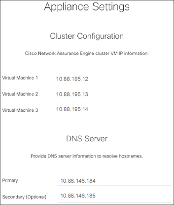
Figure 9-23 NAE Cluster and DNS Configuration
Step 5. Complete the fields for the NTP server and SMTP server, as shown in Figure 9-24, and click Submit.

Figure 9-24 NAE NTP and SMTP Configuration
Note
Uncheck Use External NTP Server to create a local NTP server configuration. Use proper email credentials to access the SMTP server.
Now it’s time to create assurance groups in NAE. An assurance group provides intent assurance for a group of entities at the same time. Assurance group configuration allows you to configure the entities that need to be analyzed together. Performing online analysis allows the Cisco NAE to collect data from an assurance group, build a model with the collected data, and generate results. The results are displayed on the dashboard as epochs. Use the following procedure to perform the online analysis.
Note
You must have admin credentials to access ACI in configuring assurance groups and export policy.
Step 1. From the gear icon, select Assurance Groups, as shown in Figure 9-25.

Figure 9-25 Configuring an NAE Assurance Group
Step 2. Click Create New Assurance Group, as shown in Figure 9-26.

Figure 9-26 Creating a New Assurance Group
Step 3. Complete the following fields to create the new assurance group (see Figure 9-27):
In the Name field, enter the name.
In the Description field, enter the description.
Select the Switch to Online Mode checkbox to automatically analyze the assurance group in real time.
In the Username field, enter the username to use for accessing the APIC hosts.
In the Password field, enter the password to use for accessing the APIC hosts.
From the Analysis Interval drop-down list, choose the interval at which to run the analysis. The analysis interval includes the time to collect data from the APIC and the switches, analyze the data to build a model, generate results, and display the results on the dashboard. For production environments, the recommended analysis interval is a minimum of 15 minutes. An interval below 15 minutes should be used only in lab environments or for testing.
From the Analysis Timeout drop-down list, choose the time the system needs to wait before terminating the analysis. This value should be greater than the Analysis Interval setting.
Check the Start Immediately checkbox to start the analysis of the selected assurance group immediately.
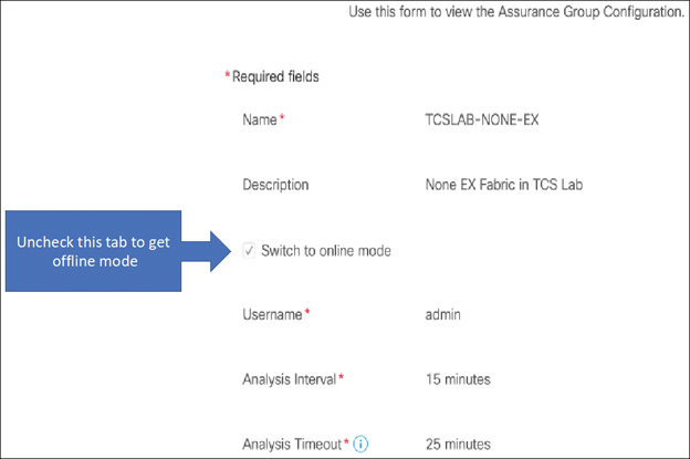
Figure 9-27 New Assurance Group Configuration
Step 4. Complete the following fields for APIC hosts (see Figure 9-28):
In the APIC Hostname 1 field, enter the APIC hostname in the format apic1.example.com.
Click the + sign to add another APIC hostname. (We recommend adding all the APIC hosts to the assurance group.)

Figure 9-28 APIC Host Configuration
Step 5. Complete the following fields for the collection settings, which are required for NAT and epoch delta analysis:
Select the Use APIC Configuration Export Policy checkbox to export the configuration policy for the policy delta.
Click Show.
Select the export format.
In the Export Policy Name field, enter the policy name.
Step 6. Click Save.
Step 7. To start the analysis of a fabric, click the Play button. To stop the analysis, click the Stop button.
Note
The status of the analysis is displayed in the Data Collection form. Cisco NAE performs analysis on only one fabric at a time. To perform analysis on another fabric, you must stop the analysis on the current fabric and then start the analysis on another fabric. In a future NAE release, you should be able to run analyses on multiple ACI fabrics at the same time.
Step 8. To view the results of the analysis, click Dashboard. To ensure that you have the correct assurance group selected to view the results, click Assurance Group and select the appropriate assurance group from the drop-down list.
Step 9. To export data, select an epoch dot on the timeline and click Export Data.
Besides real-time analysis, Cisco NAE can also perform offline analysis of your fabric. It can be helpful to perform analysis of your production ACI fabric in a lab or preproduction environment. If something unusual is found in your production ACI fabric, you can plan your change accordingly. In order to perform NAE offline analysis, you need to run a Python script on a workstation or laptop running one of the following operating systems:
Ubuntu 14.04/16.04 or later
macOS X El Capitan 10.11.6 or later
CentOS 7.x or later
Note
Windows OS is not supported.
Python version 2.7.11 or later
To run the Python script, follow these steps:
Step 1. Ensure that the Python package manager pip is installed by running the following command:
shussa36@eco:~> which pip
/usr/bin/pip
Step 2. If the location of pip is not returned, follow the instructions for your operating system to install pip:
For Ubuntu:
sudo apt-get install python-pip
sudo apt-get install build-essential libssl-dev
libffi-dev python-dev
For CentOS:
sudo yum install python-pip
For macOS:
sudo easy_install pip
Step 3. Ensure that wget is installed by running the following command:
shussa36@eco:~> which wget
/usr/bin/wget
If the location of wget is not returned, follow the instructions for your operating system to install wget:
For Ubuntu:
sudo apt-get install wget
For CentOS:
sudo yum install wget
For macOS, ensure that the package manager brew is installed in order to install wget. To install brew, run the following command:
/usr/bin/ruby -e "$(curl -fsSL
https://raw.githubusercontent.com/Homebrew/install/
master/install)"
Then install wget by running this command:
brew install wget
Step 4. Ensure that openssl is installed by running the following command:
shussa36@eco:~> which openssl
/usr/bin/openssl
Step 5. If the location of openssl is not returned, follow the instructions for your operating system to install openssl:
For Ubuntu:
sudo apt-get install openssl
For CentOS:
sudo yum install openssl
For macOS:
brew install openssl
Step 6. Verify the Python version by running the following command:
shussa36@eco:~> python -V
Python 2.7.13
After performing the preceding prerequisite steps, perform the following procedure to run an NAE offline analysis:
Step 1. Select Settings > Download Offline Collection Script to download the Python script.
Step 2. Execute the following downloaded script to collect the data for assurance:
sudo python ./cnae_data_collection.py -APIC apic1.nglab.
cisco.com -clusterName NGLAB -user nae -targetDir .
Step 3. Select Settings > Offline File Management to upload the collected data.
Step 4. Click Create New Upload.
Step 5. In the Create New Upload form, complete the following fields:
Click Browse to upload the collected data to provide one-time assurance.
In the Name field, enter the name of the file.
In the Description field, enter the description.
Step 6. Click Submit. After the file has been uploaded successfully, it is displayed in the Upload table.
Step 7. Select Settings > Offline Analysis.
Step 8. In the New Offline Analysis form, complete the following fields:
In the Analysis Name field, enter the name of the offline analysis.
From the File drop-down list, choose the file with the collected data.
From the Assurance Group drop-down list, choose the assurance group.
Optionally click the + sign to add another assurance group. Use this form if you want to define a new assurance group.
From the Analysis Timeout drop-down list, choose the time the system needs to wait before terminating the analysis. You can also enter the time the system needs to wait before terminating the analysis.
Step 9. Click Run to initiate the offline analysis. When the offline analysis is complete, the status is displayed in the New Offline Analysis form.
Step 10. To view the results of the analysis, click Dashboard.
Example: Subnet Reachability Issue
Say that you have been informed that your application EPG subnet 10.88.179.16/29 is not reachable. You verify the issue by pinging the subnet’s pervasive gateway 10.88.179.17 from your laptop and get no response, as demonstrated in Example 9-3.
Example 9-3 Confirming a Nonresponsive Subnet
laptop:~ sadiq$ ping 10.88.179.17
PING 10.88.179.17 (10.88.179.17): 56 data bytes
Request timeout for icmp_seq 0
Request timeout for icmp_seq 1
Request timeout for icmp_seq 2
^C
--- 10.88.179.17 ping statistics ---
4 packets transmitted, 0 packets received, 100.0% packet loss
To troubleshoot this particular issue in ACI, you need to manually validate the following configurations in the APIC:
The BD with the subnet is advertised outside and attached to an L3Out.
An EPG is associated with the BD and statically bound to an interface using the encapsulation VLAN.
The VLAN is part of the VLAN pool that is part of the physical domain.
The physical domain is associated with an attachable access entity profile (AAEP) that is part of interface policy group, which is part of the interface profile with a port connected to an end host.
The route reflector is configured and functioning on spines.
A contract is created between the internal application EPG and the external L3Out EPG.
The L3Out is functioning properly, and external network route peering is established.
Figure 9-29 illustrates this configuration check.

Figure 9-29 BD Subnet Configuration Steps
Manually verifying that all of this configuration is in place is time-consuming and can delay problem resolution and extend a service outage. With Cisco NAE, you can run an epoch delta analysis by selecting a time range. NAE provides meaningful error messages in the smart events dashboard to help you identify that the issue lies with the contract, as shown in Figure 9-30.
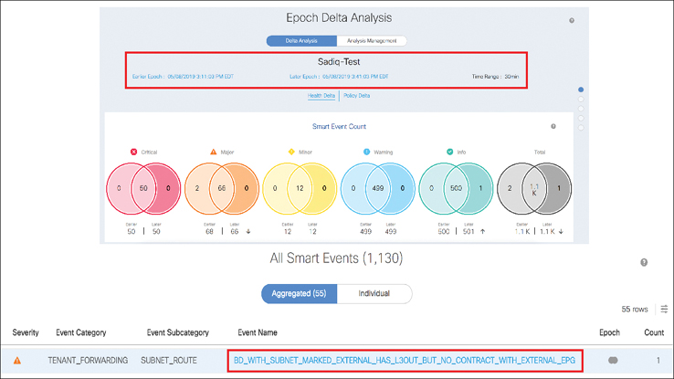
Figure 9-30 Subnet Inaccessible Error Message
If you click the error message BD_WITH_SUBNET_MARKED_EXTERNAL_HAS_L3OUT_BUT_NO_CONTRACT_WITH_EXTERNAL_EP, NAE provides complete details about the affected subnet and the BD associated to an EPG, a tenant, or a VRF instance, along with L3Out information. You can quickly verify the symptoms identified by NAE in your ACI fabric and confirm that there is no contract defined under the EPG c-pcf04-slb-int that belongs to the BD (see Figure 9-31).

Figure 9-31 Verifying an Error Message in an ACI Fabric
After applying the appropriate contracts, you can reach out to the problematic subnet, as illustrated in Figure 9-32.

Figure 9-32 Rectifying a Subnet Reachability Issue
Tetration
Today’s modern data centers are equipped with various virtualization techniques, using hypervisors and container platforms that come with their own switching layer. For example, in the hypervisor world, a virtual switch (vSwitch) or a Distributed Virtual Switch (DVS) is deployed. In the container world, a container bridge (CBR) provides the switching layer for pod and service networks. Furthermore, application services are hosted on blade systems that each come with at least a pair of switches. The story does not end there. Application workloads running as a VM or as a container can be moved anywhere at any time. This is great because it provides business agility and flexibility to grow and prosper, but it also creates lots of challenges when it comes to network operations, visibility, and security.
The Cisco Tetration analytics platform addresses these data center challenges by providing comprehensive workload-protection capability and unprecedented insights across a multi-cloud infrastructure. Tetration does this by collecting data from various entry and exit points of your application-hosting infrastructure, using software/hardware sensors and third-party sources. This data then gets fed into the Tetration analytics engine for running big data. You can pull in this information either via the Tetration web GUI, the REST API, or the Event Notification or Tetration apps, as shown in Figure 9-33.
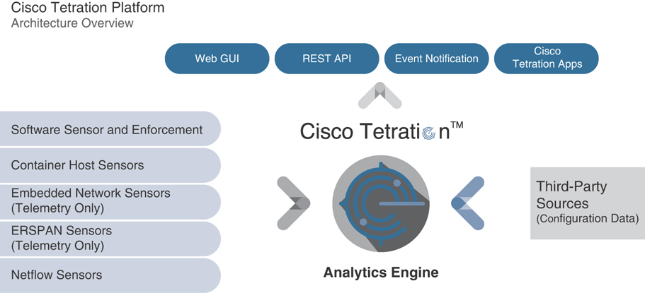
Figure 9-33 Tetration Architecture
Tetration is similar to NetFlow, but Tetration captures only the metadata of the flow. This way, all flows are captured, even in today’s high-speed networks, and there is no sampling of flows, as in the case of NetFlow captures on high-speed links. Tetration collects the network flow information and reduces device processing overhead and network consumption compared to NetFlow, and it still achieves full visibility of your network. With Tetration deep visibility software sensors, you have the ability to view per-packet flow metadata, including the following:
Application response time, SRTT, TCP resets, retransmits, window size issues, TCP performance, and bottlenecks
Open used and unused ports
Hostname, interface, and OS version
Process name, launch string, PID, life cycle data, and SHA 256 hash
Parent/child processes and privilege escalations
Installed packages and CVE exposure
Tetration can also collect third-party sources of data traffic, including the following:
Cisco AnyConnect agents
NetFlow agents
F5 agents
AWS (Amazon Web Services) agents
NetScaler agents
SPAN (ERSPAN) agents
Software Agents
Software agents are software components running on the host operating system (Linux or Windows). An agent monitors and collects network flow metadata. It also collects host information such as network interfaces, active processes, and other analytical items. The information collected by the agents is exported to the Cisco Tetration collectors running in the cluster. In addition to the telemetry data, agents have the capability to enforce security policies using firewall rules on the installed hosts.
Hardware Agents
Hardware sensors are built into the cloud-scale Nexus 9000 Series switches—EX (for ingress flows), FX, and GX switches—which capture full network flow data at very fast export intervals and without performance penalties to the normal data traffic. Like software agents, hardware agents also export data to the Cisco Tetration analytics engine. Hardware agents only provide telemetry data and cannot be used to apply security policy enforcement.
Tetration Installation and Configuration
Setup and initialization of a Tetration cluster is done by Cisco’s Advanced Services team onsite as part of the purchase agreement. The process takes roughly about a day, and you are required to provide the following details:
Site name (for example, tcslabtetration)
SSH key from a Linux machine (for example, ssh-keygen -t rsa -b 4096)
Three email addresses:
The user interface (UI) administration email (for example, [email protected])
The UI primary customer support email (for example, [email protected])
The sentinel alert email (for example, [email protected])
IP addresses:
Tetration requires two /30 subnets for point-to-point uplink to your core network.
Tetration does not support routing, so you must have a static route to the external subnet.
For the external subnet for a cluster, a /26 subnet that is reachable via the static route on the point-to-point connection
DNS resolvers
DNS domain
NTP server
SMTP server IP address/FQDN and port
SMTP username/password
Syslog server IP/FQDN and port
Syslog severity
UI FQDN (for example, tcslabtetration.tcslab.cisco.com)
Tetration Agent Download
The following procedure describes the software agent download process:
Step 1. Log in to Tetration, click the gear icon in the top-right corner, and select Agent Config.
Step 2. Select Software Agent Download, select the platform, select the agent type, and click Download.
Step 3. Select specific platforms for software agents, if needed:
Click Show Classic Agent Packages in the top-right corner of the Software Agent pane.
Click Download Action for the specific platform and agent type.
Step 4. Select Hardware Agent Download and click Download under Correct Version.
Tetration Hardware Agent Installation
The prerequisites for the hardware agent installation are as follows:
In-band management on ACI fabric
Downloading the agent
To install the hardware agent, follow these steps:
Step 1. To upload the agent to the ACI APIC, select Admin > Firmware > Firmware Repository, click Upload Firmware to APIC, and select the Tetration agent RPM (for example, tet-agent-3.1.1.53-tcslabtetration.rpm).
Step 2. To create the analytics policy, select Fabric > Fabric Policies > Policies, right-click Analytics, and select Create Analytics Policy. Type the object name of your choice (for example, tet-policy). Type the name of the Tetration cluster that you used while setting up the Tetration analytics engine (for example, Tcslabtetration). Figure 9-34 illustrates this step.

Figure 9-34 Creating an Analytics Policy
Step 3. To enable leaf switches for analytics, follow these steps:
As shown in Figure 9-35, select Fabric > Fabric Policies > Policies > Monitoring, right-click Fabric Node Controls, and select Create Fabric Node Control. Type the object name of your choice (for example, analytics). Select Analytics Priority and click Submit.

Figure 9-35 Creating a Fabric Node Control Policy
As shown in Figure 9-36, select Fabric > Fabric Policies > Switches > Leaf Switches, right-click Policy Groups, and select Create Leaf Switch Policy Group. Type the object name of your choice (for example, analytics-sw-polgrp). Select the analytics policy that you created in the previous step (that is, tet-policy) and also select analytics from the Node Control Policy drop-down. Click Submit.

Figure 9-36 Creating an Analytics Policy Group
As shown in Figure 9-37, select Fabric > Fabric Policies > Switches > Leaf Switches, right-click Profile, and select Create Leaf Switch Profile. Type the object name of your choice (for example, leaf-sw-prof). On the right-hand side of the pane, under Switch Association, click the + sign. Type the name of your choice (for example, all) and select the leaf switches that you would like to enable for Tetration analytics. Choose the Policy Group you created earlier. Click Submit.

Figure 9-37 Create Analytics Profile
Step 4. As shown in Figure 9-38, verify the hardware agents for the ACI fabric in Tetration by selecting the Monitoring drop-down in the top-right corner and then selecting Agents > Hardware Switch and verifying that your fabric is in the inventory.

Figure 9-38 Verifying Tetration Hardware Agents
Tetration Software Agent Installation (Linux)
To install the Tetration software agent on Linux, the following dependencies are required:
lsof
ps
whoami
The default shell available in the platform (sh, ksh, or bash)
unzip
To install the software agent in Linux, follow these steps:
Step 1. Click the Settings menu in the top-right corner.
Step 2. Select Agent Config. The Agent Config page displays.
Step 3. Click the Software Agent Download tab and, in the Select Platform section, choose Linux. In the Select Agent Type section, choose either Deep Visibility or Enforcement. Click the Download Installer button and save the file to the local disk.
Step 4. Copy the installer shell script to all the Linux hosts for deployment and execute the script with root privilege:
chmod u+x tetration_installer_sensor_linux.sh
sudo ./tetration
Verifying the Linux Tetration Installation
To verify the Tetration installation, use the following commands:
ps -ef
netstat -an | grep 5640
Software Agent Installation (Windows)
To install the Tetration software agent on Windows, the following dependencies are required:
Administrator privileges (both installation and service execution)
Npcap version 0.94 (or later)
Note
If the Npcap driver is not already installed, it will be installed silently.
PowerShell Version 4.0 or later if the agent is installed via an installer script
The latest service packs available for the Windows platforms (provided by Microsoft)
The steps for installing the software agent in Windows are as follows:
Step 1. Click the Settings menu in the top-right corner.
Step 2. Select Agent Config. The Agent Config page displays.
Step 3. Click the Software Agent Download tab and, in the Select Platform section, choose Windows. In the Select Agent Type section, choose either Deep Visibility or Enforcement. Click the Download Installer button and save the file to the local disk.
Step 4. Right-click the PowerShell script to run it in PowerShell.
The agent is downloaded and installed.
Verifying the Windows Tetration Installation
To verify the Tetration installation, use the following command:
netstat | findstr 5640
Figure 9-39 shows the Tetration software agent running in Windows.

Figure 9-39 Tetration Software Agent in Windows
Tetration System Monitoring
In order to use alerting in the Tetration platform, you must use the Tetration Alerts Notification (TAN) agent. In order to install the TAN agent, perform the following steps:
Step 1. Download the OVA file from cisco.com and download the TAN agent (by selecting Alerts > Configuration > Notifiers > Download).
Step 2. On a local Linux machine, create the cfg directory by entering the following command:
mkdir mon_cfg
Then create the file ip_config in this directory and add the IP address to the file in <CIDR> <GATEWAY IP> format such as (172.30.20.10/24 172.30.20.1). Create the file host_name and include the hostname in this file. Copy the TAN agent file tet-alerts-notifier.tar.gz to the cfg directory.
Step 3. Create an ISO file of the directory by running the following command:
mkisofs -r -o monitortet.iso mon_cfg
Step 4. Create a virtual machine from the OVA that has at least the following specs:
8 single-threaded cores
8 GB of memory
40 GB disk space
1 interface in bridge mode
Step 5. Upload the ISO file to a datastore and attach it to the VM’s CD/DVD drive, as shown in Figure 9-40. Boot the VM.

Figure 9-40 Attaching a Datastore ISO File to a CD/DVD Drive
When the TAN agent is installed, you see the notification Active under Publishers. You can now map alert types to publisher types, as shown in Figure 9-41.
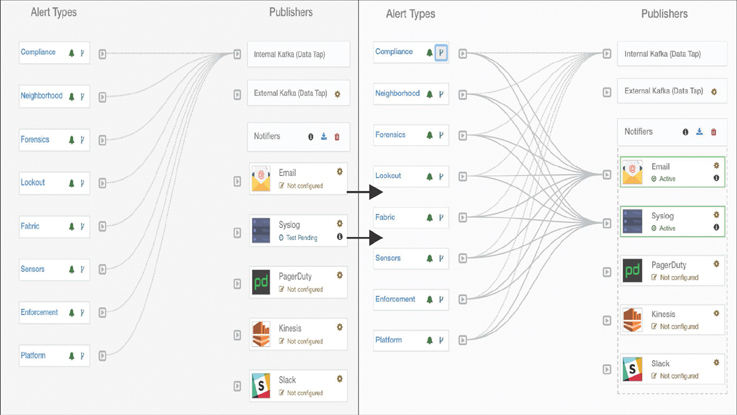
Figure 9-41 Mapping Alert Types to Publisher Types
Configuring Email Alerts
Email alerts from a cluster come from the alert email you set up during the initial configuration of the Tetration cluster. You can send to either default recipients or distribution groups. You need the TAN agent and the SMTP server/relay.
Go to Alerts > Configuration, select the gear icon, and configure the SMTP parameters as shown in Figure 9-42.

Figure 9-42 Email Alerts
Enabling Syslog
To enable syslog, you must have the TAN agent configured. If the TAN agent is installed, then you can configure to send messages to a syslog server.
Go to Alerts > Configuration, select the gear icon, and configure your syslog protocol, server address, and port number, as shown in Figure 9-43.
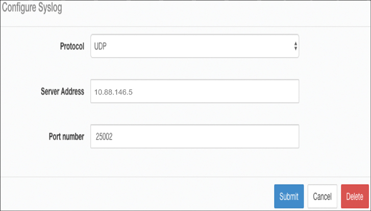
Figure 9-43 Configuring Syslog in Tetration
Next, select the alert types of your choice and configure the recipient to send alerts to the publisher of your choice. Be sure to select the appropriate alert severity level, as shown in Figure 9-44.

Figure 9-44 Enabling Alert Types
Tetration Scopes
Scopes are used to group data center applications and roles. They give you fine-grained control for management in Cisco Tetration. Scopes are organized in a hierarchical fashion as a set of trees with the root corresponding VRF instance. Each scope tree hierarchy represents disjointed data that does not overlap, as illustrated in Figure 9-45.

Figure 9-45 Scope Tree
To create a new scope, you need to perform the following procedure in the Tetration GUI:
Step 1. Click on the gear icon in the top-right corner and select Scopes.
Step 2. Go to the parent scope CSCO.
Step 3. Click Create New Scope, enter the application name, and enter the query (from the CMDB app name column EX:*Application = CaaS). Then click Create.
Step 4. Click the newly created scope and continue creating the layers of the tree shown in Figure 9-45.
Tetration Applications
Applications play a central role in Cisco Tetration, providing features such as policy enforcement, application dependency mapping (ADM), and visibility.
To create an application, follow these steps:
Step 1. Log in to Tetration and, in the left pane, select Applications > Create New Application Workspace.
Step 2. In the Create New Application Workspace window, type the application name and description. Select the scope and uncheck Dynamic Mode (because you don’t want cluster queries to overlap). Then click Create Application, as shown in Figure 9-46.

Figure 9-46 Creating an Application
Once an application is created, you can enter it. You do not see any policies until ADM is run against the application with the desired start and end times. After the agents see enough Tetration flows for a few days or weeks, ADM should be run.
Application Dependency Mapping (ADM)
ADM runs groups of similar endpoints of a workspace into clusters and generates security policies (whitelists) among the clusters. To run (or rerun) ADM, you select the time range for gathering data on the endpoints (for computing similarities and policies), and you can change other run parameters (the run configuration). After this, you can launch a run and explore, modify, and approve the results.
External Orchestrators
External orchestrators, such as vCenter and Kubernetes, provide a user interface to the Tetration analytics engine. Orchestrators provide inventory learning for Cisco Tetration in the form of annotations.
To create an external orchestrator, follow these steps:
Step 1. In the left pane of the Tetration GUI, select Visibility > External Orchestrators.
Step 2. Select Create New Configurations on the External Orchestrator page.
Step 3. Fill in the information for the specific orchestrator that is being added, as shown in Figure 9-47.

Figure 9-47 Adding an External Orchestrator
Tetration Code Upgrades
Tetration code upgrades are completed through the Tetration GUI. To update the Tetration code, follow these steps:
Step 1. Click the wrench icon in the left pane and select Upgrade.
Step 2. Select Send Upgrade Link, and an email goes out to the administrative account with the upgrade link.
Step 3. Upload the specified files and click Continue, as shown in Figure 9-48.
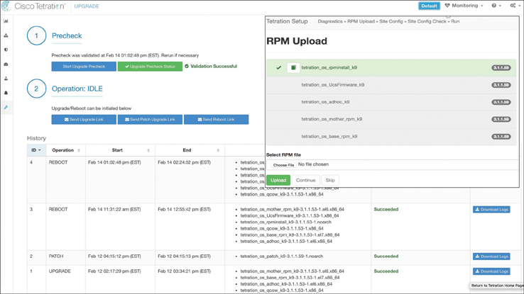
Figure 9-48 Tetration Code Upgrade
Tetration Patch Upgrade
Tetration patching is completed through the Tetration GUI. To update the Tetration code, follow these steps:
Step 1. Click the wrench icon in the left pane and select Upgrade.
Step 2. Select Send Patch Upgrade Link, and an email goes out to the administrative account with the upgrade link (see Figure 9-49).
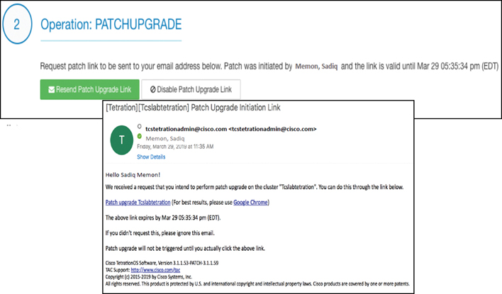
Figure 9-49 Tetration Patch Upgrade
Step 3. In the message that goes to the administrative account, click Patch upgrade Tcslabtetration, and a browser window opens.
Step 4. In the browser window, select the patch RPM file and click Upload, as shown in Figure 9-50.
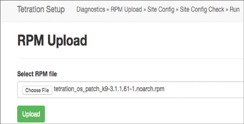
Figure 9-50 RPM Upload
Tetration Cluster Reboot
Use the following process to reboot a Tetration cluster:
Step 1. Click the wrench icon in the left pane and select Upgrade.
Step 2. Select Send Reboot Link, and an email goes out to the administrative account with the reboot link.
Step 3. In the message that goes to the administrative account, click the reboot link. Tetration takes you to the setup UI.
From this point, the process is the same as for upgrades.
Tetration Cluster Shutdown
To shut down a Tetration cluster, you must use a POST operation in the GUI. Cluster shutdown stops all running Tetration processes and powers down all individual bare-metal servers. Follow these steps to shut down a cluster:
Step 1. Click the wrench icon in the left pane and select Explore.
Step 2. Choose the POST action.
Step 3. Enter orchestrator.service.consul as the snapshot host.
Step 4. Enter cluster_powerdown?args=--start as the snapshot path.
Step 5. Click Send.
Figure 9-51 illustrates this process.
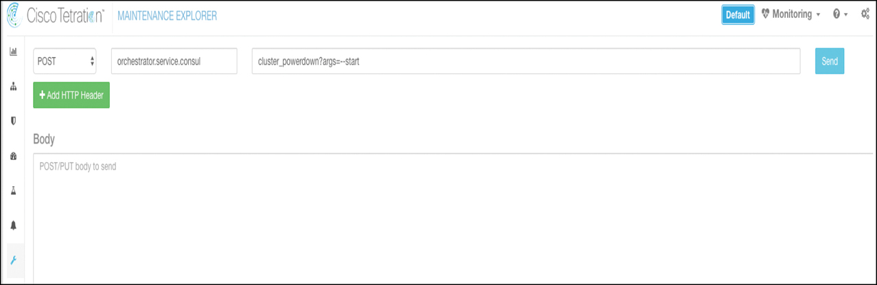
Figure 9-51 Tetration Cluster Shutdown
Example: Workload Security with Tetration
Say that you have received a call from a customer, who says that her web application has been performing slowly for the past few days. You examine the ACI infrastructure and find that the leaf interface through which the web server is connected is showing congestion. Figure 9-52 shows the network topology for this example.
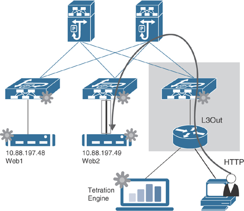
Figure 9-52 Web Application Hosting Network Topology
Your company has recently deployed Cisco Tetration for network visibility and workload security. You log in to the Tetration engine and run a flow search for a specific time range. You observe a spike in traffic flow on May 31, at around 9 p.m. Upon further investigation, you discover that another web server, web1, is pulling SNMP data from the impacted web server, web2, as shown in Figure 9-53.

Figure 9-53 Traffic Flow Analysis
This is indeed suspicious behavior because you only run web services on your web server providing services to customers and nothing else. So how is it possible that the SNMP daemon is running on web2, and web1 is pulling data using SNMP? When you check the workload profile of web2, you find that on May 31, 2019, at 07:29:38pm (EDT), someone installed the SNMP daemon on web2, indicating the process binary hash. Luckily, web2 has the Tetration Enforcement agent installed, as shown in Figure 9-54.

Figure 9-54 SNMP Daemon Process Binary Hash
You create a security policy to allow only ICMP and HTTPS traffic and apply the Enforcement agent to a scope that includes all web servers. When Tetration enforces the policy, web2 stops responding to any SNMP queries and starts performing normal application web serving for your customers, as shown in Figure 9-55.
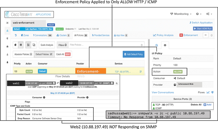
Figure 9-55 Tetration Policy Enforcement
This example clearly shows the benefit of Tetration providing network visibility and workload security.
Monitoring Through the REST API
With the industry boom in SDN, where network infrastructure is now provisioned and managed programmatically through the Representational State Transfer (REST) application programming interface (API), network engineers can use the REST interface for monitoring their software-defined network infrastructure as well. As explained in the previous chapters, in ACI, all the configuration, statistical data, faults, events, and audit logs are stored on an APIC, which provides a suitable foundation for REST calls to send this data to external devices for further analysis and alerting. SNMP and syslog are two monitoring protocols that have been used on network devices for decades; they both work on UDP, which is a connectionless protocol and does not guarantee traffic flow all the time. SNMP sends traps to an external management station, and syslog sends system messages to an external logging server during failure events. Both of these cases involve push operations using the connectionless protocol UDP; in contrast, the REST API pulls data from an APIC. Likewise, an SNMP query is a pull operation. However, running SNMP queries from multiple management stations and especially pulling full routing tables may result in CPU spikes on traditional switches such as the Cisco Catalyst 6500. The REST method is a much lighter operation on network devices. Until SDN is prevalent in the industry, there will continue to be debate about which option is the best.
REST is a client/server communication method based on TCP using HTTP or HTTPS, where the client makes a resource request to a server and, in response, the server transfers to the client a representation of the state of the requested resource. The REST API accepts and returns HTTP or HTTPS messages that contain documents in JavaScript Object Notation (JSON) or Extensible Markup Language (XML) format. A request generally consists of the following:
HTTP(S) method: Defines what kind of operation to perform
Header: Allows the client to pass along the request information
Path: Identifies the location of a resource
Message body: Contains data
Three HTTP(S) methods are used in requests to interact with resources in an ACI-based REST system:
GET: Retrieves a specific resource or a collection of resources
POST: Creates or updates a resource
DELETE: Removes a specific resource
POST and DELETE methods are idempotent, meaning that there is no additional effect if they are called multiple times with the same input parameters. However, the GET method is nullipotent, meaning that no matter how many times it is executed, there is no change in the MIT object model (read-only operation), regardless of the input parameter.
Note
The PUT method is a valid REST API method that is used primarily to modify an existing resource; however, it is not supported in ACI.
Before we get into performing a read-only GET request to pull statistical data from an APIC, it is important to understand the format of the URL used in the call, as shown in Figure 9-56.

Figure 9-56 REST API URL Format
There is a slight difference in the URI resource path when running a REST query against a regular managed object than when running a REST query against a specific object node (or object instance) or an object class. For example, to get information about the tenant managed object named t01, you use the following URL, where the resource path contains the DN of the managed object (/uni/tn-t01):
https://{{apic-host-or-ip}}/api/mo/uni/tn-t01.json
If you want to pull some statistics from a node managed object, you use the following URL, where the resource path contains the DN of the managed object (/topology/pod-ID/node-ID/sys/ch/ftslot-number):
https://{{apic-host-or-ip}}/api/mo/topology/pod-1/node-1001/sys/ch/ftslot-1.json
To retrieve information about a class of objects, you use the following URL, where the resource path is /class/class-name:
https://{{apic-host-or-ip}}/api/class/fvTenant.json
The REST API offers a wide range of filter options to help narrow down the scope of a query in the URI to locate the intended resource quickly. You can apply the filters in your URI by starting with the ? symbol. If you want to join multiple queries, you use the & symbol.
For example, to pull the operational status of leaf node 1001, you can run the following REST query against the node 1001 MO containing DN topology/pod-1/node-1001/sys and filter a child object class eqptCh by using the filters query-target=children and target-subtree-class. Note that the filter section starts with the ? symbol, and the filters are joined with the & symbol.
https://{{apic-host-or-ip}}/api/mo/topology/pod-1/node-1001/sys.json?query-target=children&target-subtree-class=eqptCh
Note
The REST API and other programmability techniques are discussed in Chapter 8, “Automation and Orchestration.” This section just provides a refresher for you to understand the examples shown below for monitoring the ACI fabric using REST.
Let’s now dive in to some examples of monitoring an APIC, network nodes such as leafs and spines, and applications by using REST API.
Monitoring an APIC
This section demonstrates monitoring of APIC-related components using the REST API.
Monitoring CPU and Memory
An APIC provides information regarding the health status of a CPU as well as memory utilization by creating instances of the process entity class procEntity. The procEntity object class contains the following useful properties:
cpuPct: CPU utilization
maxMemAlloc: The maximum memory allocated for the system
memFree: The maximum amount of memory available for the system
To retrieve information about APIC CPU and memory usage, you can use the REST API call shown in Example 9-4.
Example 9-4 Retrieving Information About APIC CPU and Memory Usage
GET Operation
URL: https://{{apic-host-or-ip}}/api/class/procEntity.json
{
    "totalCount": "3",
    "imdata": [
        {
            "procEntity": {
                "attributes": {
                    "adminSt": "enabled",
                    "childAction": "",
                    "cpuPct": "3",
                    "dn": "topology/pod-1/node-1/sys/proc"
                   "maxMemAlloc": "21941292",
                    "memFree": "109550112",
                    "modTs": "2019-12-09T01:04:33.268-05:00",
                    "monPolDn": "uni/fabric/monfab-default",
                    "name": "",
                    "operErr": "",
                    "operSt": "enabled",
                    "status": ""
                }
            }
        },
        {
            "procEntity": {
                "attributes": {
                    "adminSt": "enabled",
                    "childAction": "",
                    "cpuPct": "4",
                    "dn": "topology/pod-1/node-2/sys/proc",
                    "maxMemAlloc": "19891584",
                    "memFree": "111525332",
                    "modTs": "2019-12-09T01:04:32.971-05:00",
                    "monPolDn": "uni/fabric/monfab-default",
                    "name": "",
                    "operErr": "",
                    "operSt": "enabled",
                    "status": ""
                 }
            }
        },
        {
            "procEntity": {
                "attributes": {
                    "adminSt": "enabled",
                    "childAction": "",
                    "cpuPct": "4",
                    "dn": "topology/pod-1/node-3/sys/proc",
                    "maxMemAlloc": "16422600",
                    "memFree": "115001260",
                    "modTs": "2019-12-09T01:04:38.641-05:00",
                    "monPolDn": "uni/fabric/monfab-default",
                    "name": "",
                    "operErr": "",
                    "operSt": "enabled",
                    "status": ""
                }
            }
        }
    ]
}
Monitoring Disk Utilization
An APIC is a server with several disks and file systems present. The REST API provides easy access to disk space utilization of all partitions on the system. The output is similar to the output you get when you run the df (diskfree) command on an APIC in the Bash shell via the CLI.
To retrieve information about APIC disk utilization, you can use the REST API call shown in Example 9-5.
Example 9-5 Retrieving Information About APIC Disk Utilization
GET Operation
URL: https://{{apic-ip}}/api/class/eqptStorage.json
{
    "totalCount": "115",
    "imdata": [
        {
            "eqptStorage": {
                "attributes": {
                    "available": "2584188",
                    "blocks": "2817056",
                    "capUtilized": "3",
                    "childAction": "",
                    "device": "",
                    "dn": "topology/pod-1/node-1/sys/ch/p-[/boot]-f-[/dev/sda1]",
                    "failReason": "",
                    "fileSystem": "/dev/sda1",
                    "firmwareVersion": "",
                    "lcOwn": "local",
                    "mediaWearout": "100",
                    "modTs": "2019-10-15T12:30:54.694-05:00",
                    "model": "",
                    "monPolDn": "uni/fabric/monfab-default",
                    "mount": "/boot",
                    "name": "/boot",
                    "nameAlias": "",
                    "operSt": "ok",
                    "serial": "",
                    "status": "",
                    "used": "70052"
                }
            }
        },
        {
            "eqptStorage": {
                "attributes": {
                    "available": "37477520",
                    "blocks": "41153856",
                    "capUtilized": "5",
                    "childAction": "",
                    "device": "",
                    "dn": "topology/pod-1/node-1/sys/ch/p-[/logs]-f-
  [/dev/mapper/vg_ifc0-logs]",
                    "failReason": "",
                    "fileSystem": "/dev/mapper/vg_ifc0-logs",
                    "firmwareVersion": "",
                    "lcOwn": "local",
                    "mediaWearout": "100",
                    "modTs": "2019-12-09T22:11:22.634-05:00",
                    "model": "",
                    "monPolDn": "uni/fabric/monfab-default",
                    "mount": "/logs",
                    "name": "/logs",
                    "nameAlias": "",
                    "operSt": "ok",
                    "serial": "",
                    "status": "",
                    "used": "1562800"
                }
            }
        },
        {
            "eqptStorage": {
                "attributes": { ........... Command output truncated.
Monitoring Interfaces
A Cisco APIC is recommended to connect to two leaf switches for redundancy. This involves using 10 Gbps interfaces. In addition, an APIC has two 1 Gbps interfaces for OOB management connectivity. An APIC configures these interfaces into two separate bonded interfaces:
Bond0: This is the bond interface between the two 10 Gbps interfaces used to connect to the fabric via a pair of leaf switches.
Bond1: This is the bond interface between the two 1 Gbps interfaces used to connect to the OOB management network.
If you are using the in-band management network, the Bond0 fabric interface is carved into two subinterfaces: one for ACI fabric traffic (bond0.{infra-vlan}) and the other one for in-band management traffic (bond0.{Inband-vlan}).
To retrieve information about APIC interface status, you can use the REST API call shown in Example 9-6 with filter options to narrow down the search.
Example 9-6 Retrieving Information About APIC Interface Status
GET Operation
URL: https://{{apic-ip}}/api/mo/topology/pod-1/node-1/sys.json?query-
  target=subtree&target-subtree-class=l3EncRtdIf
{
    "totalCount": "3",
    "imdata": [
        {
            "l3EncRtdIf": {
                "attributes": {
                    "adminSt": "up",
                    "bw": "0",
                    "childAction": "",
                    "delay": "1",
                    "descr": "",
                    "dn": "topology/pod-1/node-1/sys/inst-bond1/encrtd-[po1.4093]",
                    "encap": "unknown",
                    "ethpmCfgFailedBmp": "",
                    "ethpmCfgFailedTs": "00:00:00:00.000",
                    "ethpmCfgState": "0",
                    "id": "po1.4093",
                    "ifConnDn": "",
                    "lcOwn": "local",
                    "linkLogEn": "default",
                    "modTs": "2019-08-12T10:08:36.569-05:00",
                    "monPolDn": "uni/tn-common/monepg-default",
                    "mtu": "1500",
                    "mtuInherit": "yes",
                    "name": "bond1",
                    "routerMac": "00:A3:8E:E2:CF:2E",
                    "status": ""
                }
            }
        },
       {
            "l3EncRtdIf": {
                "attributes": {
                    "adminSt": "up",
                    "bw": "0",
                    "childAction": "",
                    "delay": "1",
                    "descr": "",
                    "dn": "topology/pod-1/node-1/sys/inst-bond0/encrtd-[po1.4093]",
                    "encap": "vlan-4093",
                    "ethpmCfgFailedBmp": "",
                    "ethpmCfgFailedTs": "00:00:00:00.000",
                    "ethpmCfgState": "0",
                    "id": "po1.4093",
                    "ifConnDn": "",
                    "lcOwn": "local",
                    "linkLogEn": "default",
                    "modTs": "2019-08-12T10:08:36.569-05:00",
                    "monPolDn": "uni/tn-common/monepg-default",
                    "mtu": "1496",
                    "mtuInherit": "yes",
                    "name": "bond0.4093",
                    "routerMac": "40:01:7A:B9:3B:0C",
                    "status": ""
                }
            }
        },
        {
            "l3EncRtdIf": {
                "attributes": {
                    "adminSt": "up",
                    "bw": "0",
                    "childAction": "",
                    "delay": "1",
                    "descr": "",
                    "dn": "topology/pod-1/node-1/sys/inst-bond0/encrtd-[po1.51]",
                    "encap": "vlan-51",
                    "ethpmCfgFailedBmp": "",
                    "ethpmCfgFailedTs": "00:00:00:00.000",
                    "ethpmCfgState": "0",
                    "id": "po1.51",
                    "ifConnDn": "",
                    "lcOwn": "local",
                    "linkLogEn": "default",
                    "modTs": "2019-10-15T12:30:21.012-05:00",
                    "monPolDn": "",
                    "mtu": "1496",
                    "mtuInherit": "yes",
                    "name": "bond0.51",
                    "routerMac": "40:01:7A:B9:3B:0C",
                    "status": ""
                }
            }
        }
    ]
}
Monitoring the APIC Cluster State
ACI controllers run in a cluster of typically three, five, or seven APICs, depending on the number of leaf nodes supported in the fabric. It is important to monitor the state of a cluster. In order to do that, you can run the REST API call shown in Example 9-7.
Example 9-7 REST API Call to Monitor the APIC Cluster State
GET Operation
URL: https://{{apic-ip}}/api/mo/topology/pod-1/node-1/sys.json
{
"totalCount": "1",
    "imdata": [
        {
            "topSystem": {
                "attributes": {
                    "address": "10.2.0.1",
                    "bootstrapState": "none",
                    "childAction": "",
                    "configIssues": "",
                    "controlPlaneMTU": "9000",
                    "currentTime": "2019-12-09T23:45:39.337-05:00",
                    "dn": "topology/pod-1/node-1/sys",
                    "enforceSubnetCheck": "no",
                    "etepAddr": "0.0.0.0",
                    "fabricDomain": "f01",
                    "fabricId": "1",
                    "fabricMAC": "00:22:BD:F8:19:FF",
                    "id": "1",
                    "inbMgmtAddr": "100.100.100.1",
                    "inbMgmtAddr6": "fc00::1",
                   "inbMgmtAddr6Mask": "0",
                    "inbMgmtAddrMask": "26",
                    "inbMgmtGateway": "100.100.100.63",
                    "inbMgmtGateway6": "::",
                    "lcOwn": "local",
                    "modTs": "2019-08-13T13:28:56.006-05:00",
                    "mode": "unspecified",
                    "monPolDn": "uni/fabric/monfab-default",
                    "name": "apic1",
                    "nameAlias": "",
                    "nodeType": "unspecified",
                    "oobMgmtAddr": "200.200.200.1",
                    "oobMgmtAddr6": "fe80::2a3:8eff:fee2:cf2e",
                    "oobMgmtAddr6Mask": "0",
                    "oobMgmtAddrMask": "26",
                    "oobMgmtGateway": "200.200.200.63",
                    "oobMgmtGateway6": "2001:420:28e:2020:acc:68ff:fe28:b540",
                    "podId": "1",
                    "remoteNetworkId": "0",
                    "remoteNode": "no",
                    "role": "controller",
                    "serial": "FCH2113T1GY",
                    "siteId": "0",
                    "state": "in-service",
                    "status": "",
                    "systemUpTime": "55:11:17:22.000",
                    "tepPool": "0.0.0.0",
                    "unicastXrEpLearnDisable": "no"
                }
            }
        }
    ]
}
Monitoring Leafs and Spines
This section demonstrates monitoring of leafs and spines using the REST API.
Monitoring CPU Utilization
CPU utilization on leafs and spines can be monitored using the following object classes, depending on the desired sampling interval and update cycle:
procSysCPU5min: Represents the most current statistics for system CPU in a 5-minute sampling interval and updates every 10 seconds.
procSysCPU15min: Represents the most current statistics for system CPU in a 15-minute sampling interval and updates every 5 minutes.
procSysCPU1h: Represents the most current statistics for system CPU in a 1-hour sampling interval and updates every 15 minutes.
procSysCPU1d: Represents the most current statistics for system CPU in a 1-day sampling interval and updates every hour.
procSysCPU1w: Represents the most current statistics for system CPU in a 1-week sampling interval and updates every day.
procSysCPU1mo: Represents the most current statistics for system CPU in a 1-month sampling interval and updates every day.
procSysCPU1qtr: Represents the most current statistics for system CPU in a 1-quarter sampling interval and updates every day.
procSysCPU1year: Represents the most current statistics for system CPU in a 1-year sampling interval and updates every day.
In order to monitor CPU utilization on leafs and spines, you need to run the REST API call shown in Example 9-8, which shows CPU utilization on a 1-hour sampling interval.
Example 9-8 Monitoring CPU Utilization on Leafs and Spines
GET Operation
URL: https://{{apic-ip}}/api/class/procSysCPU1h.json
{
    "totalCount": "19",
    "imdata": [
        {
            "procSysCPU1h": {
                "attributes": {
                    "childAction": "",
                    "cnt": "1",
                    "dn": "topology/pod-1/node-1001/sys/procsys/CDprocSysCPU1h",
                    "idleAverage1mAvg": "93.407647",
                    "idleAverage1mLast": "93.407647",
                    "idleAverage1mMax": "93.407647",
                    "idleAverage1mMin": "93.407647",
                    "idleAverage1mSpct": "0",
                    "idleAverage1mThr": "",
                    "idleAverage1mTr": "0.000000",
                    "idleAverage1mTrBase": "93.513571",
                    "idleAverage1mTtl": "93.407647",
                    "idleAvg": "93.409271",
                    "idleLast": "93.409271",
                    "idleMax": "93.409271",
                    "idleMin": "93.409271",
                    "idleSpct": "0",
                    "idleThr": "",
                    "idleTr": "0.000000",
                    "idleTrBase": "93.512008",
                    "idleTtl": "93.409271",
                    "kernelAverage1mAvg": "3.027181",
                    "kernelAverage1mLast": "3.027181",
                    "kernelAverage1mMax": "3.027181",
                    "kernelAverage1mMin": "3.027181",
                    "kernelAverage1mSpct": "0",
                    "kernelAverage1mThr": "",
                    "kernelAverage1mTr": "0.000000",
                    "kernelAverage1mTrBase": "3.001924",
                    "kernelAverage1mTtl": "3.027181",
                    "kernelAvg": "3.025889",
                    "kernelLast": "3.025889",
                    "kernelMax": "3.025889",
                    "kernelMin": "3.025889",
                    "kernelSpct": "0",
                    "kernelThr": "",
                    "kernelTr": "0.000000",
                    "kernelTrBase": "3.002168",
                    "kernelTtl": "3.025889",
                    "lastCollOffset": "900",
                    "repIntvEnd": "2019-12-11T01:14:47.233-05:00",
                    "repIntvStart": "2019-12-11T00:59:47.231-05:00",
                    "status": "",
                    "userAverage1mAvg": "3.565172",
                    "userAverage1mLast": "3.565172",
                    "userAverage1mMax": "3.565172",
                    "userAverage1mMin": "3.565172",
                    "userAverage1mSpct": "0",
                    "userAverage1mThr": "",
                    "userAverage1mTr": "0.000000",
                    "userAverage1mTrBase": "3.484505",
                    "userAverage1mTtl": "3.565172",
                    "userAvg": "3.564840",
                    "userLast": "3.564840",
                    "userMax": "3.564840",
                    "userMin": "3.564840",
                    "userSpct": "0",
                    "userThr": "",
                    "userTr": "0.000000",
                    "userTrBase": "3.485824",
                    "userTtl": "3.564840"
                }
            }
        },
        {
            "procSysCPU1h": {  ........... Command output truncated.
Monitoring Memory Utilization
Much like CPU utilization, memory utilization on switches can be monitored using the following classes, depending on the desired sampling interval and update cycle:
procSysMem5min: Represents the most current statistics for system memory in a 5-minute sampling interval and updates every 10 seconds.
procSysMem15min: Represents the most current statistics for system memory in a 15-minute sampling interval and updates every 5 minutes.
procSysMem1h: Represents the most current statistics for system memory in a 1-hour sampling interval and updates every 15 minutes.
procSysMem1d: Represents the most current statistics for system memory in a 1-day sampling interval and updates every hour.
procSysMem1w: Represents the most current statistics for system memory in a 1-week sampling interval and updates every day.
procSysMem1mo: Represents the most current statistics for system memory in a 1-month sampling interval and updates every day.
procSysMem1qtr: Represents the most current statistics for system memory in a 1-quarter sampling interval and updates every day.
procSysMem1year: Represents the most current statistics for system memory in a 1-year sampling interval and updates every day.
In order to monitor memory utilization on leafs and spines, you need to run the REST API call in Example 9-9, which shows memory utilization for a 1-hour sampling interval.
Example 9-9 Monitoring Memory Utilization on Leafs and Spines
GET Operation
URL: https://{{apic-ip}}/api/class/procSysMem1h.json
{
{
    "totalCount": "19",
    "imdata": [
        {
            "procSysMem1h": {
                "attributes": {
                    "childAction": "",
                    "cnt": "0",
                    "dn": "topology/pod-1/node-1001/sys/procsys/CDprocSysMem1h",
                    "freeAvg": "0",
                    "freeLast": "12935932",
                    "freeMax": "0",
                    "freeMin": "0",
                    "freeSpct": "0",
                    "freeThr": "",
                    "freeTr": "0",
                    "freeTrBase": "12920790",
                    "freeTtl": "0",
                    "lastCollOffset": "0",
                    "repIntvEnd": "2019-12-11T01:59:47.232-05:00",
                    "repIntvStart": "2019-12-11T01:59:47.232-05:00",
                    "status": "",
                    "totalAvg": "0",
                    "totalLast": "24499860",
                    "totalMax": "0",
                    "totalMin": "0",
                    "totalSpct": "0",
                    "totalThr": "",
                    "totalTr": "0",
                    "totalTrBase": "24499860",
                    "totalTtl": "0",
                    "usedAvg": "0",
                    "usedLast": "11563926",
                    "usedMax": "0",
                    "usedMin": "0",
                    "usedSpct": "0",
                    "usedThr": "",
                    "usedTr": "0",
                    "usedTrBase": "11579068",
                    "usedTtl": "0"
                }
            }
        },
        {
            "procSysMem1h": {  ........... Command output truncated.
Monitoring Power Supply Unit (PSU) Status
The power supply is a critical component of a network device. To ensure that the power supplies in a unit are functioning correctly, you can run the REST API call shown in Example 9-10.
Note
Depending on the number of power supplies in a device that you would like to monitor, you can choose the appropriate PSU slot number in your REST calls.
Example 9-10 Monitoring Power Supply Unit Status
GET Operation
URL: https://{{apic-ip}}/api/mo/topology/pod-1/node-1001/sys/ch/psuslot-1.json
{
    "totalCount": "1",
    "imdata": [
        {
            "eqptPsuSlot": {
                "attributes": {
                    "cardOperSt": "unknown",
                    "childAction": "",
                    "descr": "PSU Slot N9K-PAC-3000W-B",
                    "dn": "topology/pod-1/node-101/sys/ch/psuslot-1",
                    "id": "1",
                    "loc": "front",
                    "modTs": "2019-10-09T17:21:14.709+00:00",
                    "monPolDn": "uni/fabric/monfab-default",
                    "operSt": "inserted",
                    "physId": "1",
                    "status": "",
                    "type": "psuslot"
                }
            }
        }
    ]
}
!! If the power is down or not connected, you will get the following output.
{
    "totalCount": "1",
    "imdata": [
        {
            "eqptPsuSlot": {
                "attributes": {
                    "cardOperSt": "unknown",
                    "childAction": "",
                    "descr": "PSU slot",
                    "dn": "topology/pod-1/node-101/sys/ch/psuslot-3",
                    "id": "3",
                    "loc": "front",
                    "modTs": "2019-10-09T17:21:14.709+00:00",
                    "monPolDn": "uni/fabric/monfab-default",
                    "operSt": "empty",
                    "physId": "3",
                    "status": "",
                    "type": "psuslot"
                }
            }
        }
    ]
}
Monitoring Fan Status
Fan assemblies in switches are required to dissipate the heat that is generated by power supplies. It’s important to monitor fan assemblies in switches to prevent devices from powering down. In order to monitor fans in switches, you need to run the REST API call shown in Example 9-11.
Note
Example 9-11 shows the status of the fan in slot 1 of the Leaf 1001 chassis.
Example 9-11 Monitoring FAN Status
GET Operation
URL: https://{{apic-ip}}/api/mo/topology/pod-1/node-1001/sys/ch/ftslot-1.json
{
    "totalCount": "1",
    "imdata": [
        {
            "eqptFtSlot": {
                "attributes": {
                    "cardOperSt": "unknown",
                    "childAction": "",
                    "descr": "Fan slot NXA-FAN-30CFM-F",
                    "dn": "topology/pod-1/node-1001/sys/ch/ftslot-1",
                    "id": "1",
                    "loc": "rear",
                    "modTs": "2019-10-15T13:55:02.593-05:00",
                    "monPolDn": "uni/fabric/monfab-default",
                    "operSt": "inserted",
                    "physId": "1",
                    "status": "",
                    "type": "fantray"
                }
            }
        }
    ]
}
Monitoring Module Status
The Nexus 9500 is a modular switch that consists of a supervisor module to process network traffic and line cards to forward network traffic. The device also uses a midplane fabric module for fast switching of packets between line cards. It is important to monitor the status of supervisor modules, line cards, and fabric modules for smooth functioning of the device. You can use the REST API call shown in Example 9-12 to determine the status of these peripherals in the switch.
Example 9-12 Monitoring Supervisor Module, Line Card, and Fabric Module Status
GET Operation
URL: https://{{apic-ip}}/api/mo/topology/pod-1/node-101/sys/ch/supslot-1/sup.json
{
    "totalCount": "1",
    "imdata": [
        {
            "eqptSupC": {
                "attributes": {
                    "childAction": "",
                    "descr": "Supervisor Module",
                    "dn": "topology/pod-1/node-101/sys/ch/supslot-1/sup",
                    "hwVer": "2.1",
                    "id": "1",
                    "macB": "18-80-90-93-9c-24",
                    "macL": "18",
                    "mfgTm": "2017-06-04T19:00:00.000-05:00",
                    "modTs": "2019-10-15T13:53:22.969-05:00",
                    "model": "N9K-SUP-B",
                    "monPolDn": "uni/fabric/monfab-default",
                    "numP": "0",
                    "operSt": "online",
                    "pwrSt": "on",
                    "rdSt": "active",
                    "rev": "B0",
                    "ser": "FOC21234SNF",
                    "status": "",
                    "swCId": "250",
                    "type": "supervisor",
                    "upTs": "2019-10-15T13:53:22.969-05:00",
                    "vendor": "Cisco Systems, Inc."
                }
            }
        }
    ]
}
GET Operation
URL: https://{{apic-ip}}/api/mo/topology/pod-1/node-101/sys/ch/lcslot-1/lc.json
{
    "totalCount": "1",
    "imdata": [
        {
            "eqptLC": {
                "attributes": {
                    "childAction": "",
                    "descr": "32p 40/100G Ethernet Module",
                    "dn": "topology/pod-1/node-101/sys/ch/lcslot-1/lc",
                    "hwVer": "1.4",
                    "id": "1",
                    "macB": "00-27-e3-45-13-a8",
                    "macL": "132",
                    "mfgTm": "2017-06-25T19:00:00.000-05:00",
                    "modTs": "2019-10-15T13:54:27.426-05:00",
                    "model": "N9K-X9732C-EX",
                    "monPolDn": "uni/fabric/monfab-default",
                    "numP": "32",
                    "operSt": "online",
                    "pwrSt": "on",
                    "rdSt": "active",
                    "rev": "B0",
                    "ser": "FOC2126018E",
                    "status": "",
                    "swCId": "270",
                    "type": "linecard",
                    "upTs": "2019-10-15T13:54:27.426-05:00",
                    "vendor": "Cisco Systems, Inc."
                }
            }
        }
    ]
}
GET Operation
URL: https://{{apic-ip}}/api/mo/topology/pod-1/node-101/sys/ch/fcslot-1/fc.json
{
    "totalCount": "1",
    "imdata": [
        {
            "eqptFC": {
                "attributes": {
                    "childAction": "",
                    "descr": "Fabric Module",
                    "dn": "topology/pod-1/node-101/sys/ch/fcslot-1/fc",
                    "hwVer": "1.0",
                    "id": "1",
                    "macB": "00-00-00-00-00-00",
                    "macL": "0",
                    "mfgTm": "2017-02-12T19:00:00.000-05:00",
                    "modTs": "2019-10-15T13:54:38.428-05:00",
                    "model": "N9K-C9504-FM-E",
                    "monPolDn": "uni/fabric/monfab-default",
                    "numP": "0",
                    "operSt": "online",
                    "pwrSt": "on",
                    "rdSt": "active",
                    "rev": "A0",
                    "ser": "FOC21070SAZ",
                    "status": "",
                    "swCId": "267",
                    "type": "fabriccard",
                    "upTs": "2019-10-15T13:54:38.428-05:00",
                    "vendor": "Cisco Systems, Inc."
                }
            }
        }
    ]
}
Monitoring Leaf/Spine Membership Status in a Fabric
Leaf and spine nodes are registered and discovered by the ACI fabric during the initial joining state. It is important to monitor whether leaf and spine switches stay connected and remain registered with the ACI fabric all the time in order for the APIC to manage and monitor them. You can use the REST API call shown in Example 9-13 to determine the leaf and spine membership status in the fabric.
Example 9-13 Monitoring Leaf and Spine Fabric Membership by Using the REST API
GET Operation
URL: https://{{apic-ip}}/api/mo/topology/pod-1/node-202/sys.json
{
    "totalCount": "1",
    "imdata": [
        {
            "topSystem": {
                "attributes": {
                    "address": "10.2.44.64",
                    "bootstrapState": "done",
                    "childAction": "",
                    "configIssues": "",
                    "controlPlaneMTU": "9000",
                    "currentTime": "2020-01-03T06:13:38.080-05:00",
                    "dn": "topology/pod-1/node-202/sys",
                    "enforceSubnetCheck": "no",
                    "etepAddr": "0.0.0.0",
                    "fabricDomain": "f02",
                    "fabricId": "1",
                    "fabricMAC": "00:22:BD:F8:19:FF",
                    "id": "202",
                    "inbMgmtAddr": "50.50.50.202",
                    "inbMgmtAddr6": "::",
                    "inbMgmtAddr6Mask": "0",
                    "inbMgmtAddrMask": "0",
                    "inbMgmtGateway": "0.0.0.0",
                    "inbMgmtGateway6": "::",
                    "lcOwn": "local",
                    "modTs": "2019-11-05T17:01:54.468-05:00",
                    "mode": "unspecified",
                    "monPolDn": "uni/fabric/monfab-default",
                    "name": "leaf202",
                    "nameAlias": "",
                    "nodeType": "unspecified",
                    "oobMgmtAddr": "60.60.60.202",
                    "oobMgmtAddr6": "::",
                    "oobMgmtAddr6Mask": "0",
                    "oobMgmtAddrMask": "0",
                    "oobMgmtGateway": "0.0.0.0",
                    "oobMgmtGateway6": "::",
                    "podId": "1",
                    "remoteNetworkId": "0",
                    "remoteNode": "no",
                    "role": "leaf",
                    "serial": "FDO212225F9",
                    "siteId": "0",
                    "state": "in-service",
                    "status": "",
                    "systemUpTime": "58:13:19:16.000",
                    "tepPool": "10.2.0.0/18",
                    "unicastXrEpLearnDisable": "no"
                }
            }
        }
    ]
}
If a node is out of service and is no longer registered with the ACI fabric, you get the output shown in Example 9-14.
Note
In this example, Node 201 is out of service.
Example 9-14 Fabric Node Out-of-Service Output Through the REST API
GET Operation
URL: https://{{apic-ip}}/api/node/mo/topology/pod-1/node-201/sys.json
{
    "totalCount": "1",
    "imdata": [
        {
            "error": {
                "attributes": {
                    "code": "1",
                    "text": "the messaging layer was unable to deliver the stimulus
  (destination (node) is marked unavailable)"
                }
            }
        }
    ]
}
You can also run a more granular REST query that targets a specific object class, such as fabricNode, to get the membership status for every node in the ACI fabric, along with device serial and model numbers, as demonstrated in Example 9-15.
Example 9-15 Pulling Fabric Node Status by Using the REST API
GET Operation
URL: https://{{apic-ip}}/api/mo/topology/pod-1.json?query-target=children&target-
  subtree-class=fabricNode
{
    "totalCount": "25",
    "imdata": [
        {
            "fabricNode": {
                "attributes": {
                    "adSt": "on",
                    "annotation": "",
                    "childAction": "",
                    "delayedHeartbeat": "no",
                    "dn": "topology/pod-1/node-1005",
                    "extMngdBy": "",
                    "fabricSt": "active",
                    "id": "1005",
                    "lastStateModTs": "2019-10-15T14:00:21.324-05:00",
                    "lcOwn": "local",
                    "modTs": "2019-10-15T14:00:46.369-05:00",
                    "model": "N9K-C93180LC-EX",
                    "monPolDn": "uni/fabric/monfab-default",
                    "name": "leaf1005",
                    "nameAlias": "",
                    "nodeType": "unspecified",
                    "role": "leaf",
                    "serial": "FDO21462QHN",
                    "status": "",
                    "uid": "0",
                    "vendor": "Cisco Systems, Inc",
                    "version": ""
                }
            }
        },
        {
            "fabricNode": {
                "attributes": {
                    "adSt": "on",
                    "annotation": "",
                    "childAction": "",
                    "delayedHeartbeat": "no",
                    "dn": "topology/pod-1/node-102",
                    "extMngdBy": "",
                    "fabricSt": "active",
                    "id": "102",
                    "lastStateModTs": "2019-10-15T13:33:38.344-05:00",
                    "lcOwn": "local",
                    "modTs": "2019-10-15T13:34:11.481-05:00",
                    "model": "N9K-C9504",
                    "monPolDn": "uni/fabric/monfab-default",
                    "name": "spine102",
                    "nameAlias": "",
                    "nodeType": "unspecified",
                    "role": "spine",
                    "serial": "FOX2126PD4S",
                    "status": "",
                    "uid": "0",
                    "vendor": "Cisco Systems, Inc",
                    "version": ""
                }
            }
        },
        {
            "fabricNode": {
                "attributes": {
                    "adSt": "on",
                    "annotation": "",
                    "childAction": "",
                    "delayedHeartbeat": "no",
                    "dn": "topology/pod-1/node-1",
                    "extMngdBy": "",
                    "fabricSt": "unknown",
                    "id": "1",
                    "lastStateModTs": "1969-12-31T19:00:00.000-05:00",
                    "lcOwn": "local",
                    "modTs": "2019-08-12T10:10:03.443-05:00",
                    "model": "APIC-SERVER-L2",
                    "monPolDn": "uni/fabric/monfab-default",
                    "name": "apic1",
                    "nameAlias": "",
                    "nodeType": "unspecified",
                    "role": "controller",
                    "serial": "FCH2113V1GX",
                    "status": "",
                    "uid": "0",
                    "vendor": "Cisco Systems, Inc",
                    "version": "A0"
                }
            }
        },
        {
            "fabricNode": {
                "attributes": {
                    "adSt": "off",
                    "annotation": "",
                    "childAction": "",
                    "delayedHeartbeat": "no",
                    "dn": "topology/pod-1/node-201",
                    "extMngdBy": "",
                    "fabricSt": "inactive",
                    "id": "201",
                    "lastStateModTs": "2019-11-05T16:50:07.568-05:00",
                    "lcOwn": "local",
                    "modTs": "2019-11-05T16:50:21.889-05:00",
                    "model": "N9K-C93180LC-EX",
                    "monPolDn": "uni/fabric/monfab-default",
                    "name": "leaf201",
                    "nameAlias": "",
                    "nodeType": "unspecified",
                    "role": "leaf",
                    "serial": "FDO212225QJ",
                    "status": "",
                    "uid": "0",
                    "vendor": "Cisco Systems, Inc",
                    "version": ""
                }
            }
        }
    ]
}
Monitoring Interface Status
Monitoring leaf and spine interface status is important especially when you face connectivity and performance issues. You can run the REST API call shown in Example 9-16 to retrieve that information.
Note
In Example 9-16, interface Ethernet1/1 on leaf Node 202 is being monitored.
Example 9-16 Monitoring the Status of Leaf and Spine Interfaces
GET Operation
URL: https://{{apic-ip}}/api/mo/topology/pod-1/node-202/sys/phys-[eth1/1]/
  dbgEtherStats.json
{
    "totalCount": "1",
    "imdata": [
        {
            "rmonEtherStats": {
                "attributes": {
                    "broadcastPkts": "40",
                    "cRCAlignErrors": "0",
                    "childAction": "",
                    "clearTs": "never",
                    "collisions": "0",
                    "dn": "topology/pod-1/node-202/sys/phys-[eth1/1]/dbgEtherStats",
                    "dropEvents": "0",
                    "fragments": "0",
                    "jabbers": "0",
                    "modTs": "never",
                    "multicastPkts": "3676300",
                    "octets": "7982783217",
                    "oversizePkts": "4726",
                    "pkts": "29858838",
                    "pkts1024to1518Octets": "2336916",
                    "pkts128to255Octets": "3625907",
                   "pkts256to511Octets": "7755066",
                    "pkts512to1023Octets": "444631",
                    "pkts64Octets": "10057075",
                    "pkts65to127Octets": "5634517",
                    "rXNoErrors": "16424455",
                    "rxGiantPkts": "0",
                    "rxOversizePkts": "2362",
                    "status": "",
                    "tXNoErrors": "13434383",
                    "txGiantPkts": "0",
                    "txOversizePkts": "2364",
                    "undersizePkts": "0"
                }
            }
        }
    ]
}
You can also run the REST calls in Example 9-17 to collect more interface-related information.
Example 9-17 provides the RX, or input-related, interface statistics.
Example 9-17 Checking Interface Unicast Packets Received by Using the REST API
GET Operation
URL: https://{{apic-ip}}/api/mo/topology/pod-1/node-202/sys/phys-[eth1/1]/
  dbgIfIn.json
{
    "totalCount": "1",
    "imdata": [
        {
            "rmonIfIn": {
                "attributes": {
                    "broadcastPkts": "19",
                    "childAction": "",
                    "clearTs": "never",
                    "discards": "0",
                    "dn": "topology/pod-1/node-202/sys/phys-[eth1/1]/dbgIfIn",
                    "errors": "0",
                    "modTs": "never",
                    "multicastPkts": "2301795",
                    "nUcastPkts": "2301814",
                    "octets": "2853600184",
                    "status": "",
                    "ucastPkts": "14376887",
                    "unknownProtos": "0"
                }
            }
        }
    ]
}
Example 9-18 provides the TX, or output-related, interface statistics.
Example 9-18 Checking Interface Unicast Packets Transmitted by Using the REST API
GET Operation
URL: https://{{apic-ip}}/api/mo/topology/pod-1/node-202/sys/phys-[eth1/1]/
  dbgIfOut.json
{
    "totalCount": "1",
    "imdata": [
        {
            "rmonIfOut": {
                "attributes": {
                    "broadcastPkts": "21",
                    "childAction": "",
                    "clearTs": "never",
                    "discards": "0",
                    "dn": "topology/pod-1/node-202/sys/phys-[eth1/1]/dbgIfOut",
                    "errors": "0",
                    "modTs": "never",
                    "multicastPkts": "1430409",
                    "nUcastPkts": "1430430",
                    "octets": "5252627292",
                    "qLen": "0",
                    "status": "",
                    "ucastPkts": "12208831"
                }
            }
        }
    ]
}
Monitoring Applications
This section provides application-related monitoring examples using the REST API.
Monitoring Application Traffic Status
To monitor network-related statistics for an application, you can investigate the aggregate amount of traffic flow to a specific application tier by executing the REST API query shown in Example 9-19.
Note
In Example 9-19, the application EPG db under application profile 3-tier in tenant t01 is being monitored.
Example 9-19 Monitoring the Aggregate Amount of Traffic Flow to a Specific Application Tier
GET Operation
URL: https://{{apic-ip}}/api/mo/uni/tn-t01/ap-3-tier/epg-db.json?query-
  target=self&rsp-subtree-include=stats
{

    "totalCount": "1",
    "imdata": [
        {
            "fvAEPg": {
                "attributes": {
                    "annotation": "",
                    "childAction": "",
                    "configIssues": "",
                    "configSt": "applied",
                    "descr": "",
                    "dn": "uni/tn-t01/ap-3-tier/epg-db",
                    "exceptionTag": "",
                    "extMngdBy": "",
                    "floodOnEncap": "disabled",
                    "fwdCtrl": "",
                    "isAttrBasedEPg": "no",
                    "isSharedSrvMsiteEPg": "no",
                    "lcOwn": "local",
                    "matchT": "AtleastOne",
                    "modTs": "2019-08-13T13:28:48.008-05:00",
                    "monPolDn": "uni/tn-t01/monepg-default",
                    "name": "db"
                    "nameAlias": "",
                    "pcEnfPref": "unenforced",
                    "pcTag": "49159",
                    "prefGrMemb": "exclude",
                    "prio": "unspecified",
                    "scope": "2949120",
                    "status": "",
                    "triggerSt": "triggerable",
                    "txId": "6341068275337697100",
                    "uid": "15374"
                },
                "children": [
               {
                        "l2IngrBytesAgHist1h": {
                            "attributes": {
                                "childAction": "deleteNonPresent",
                                "cnt": "4",
                                "dropCum": "24564298",
                                "dropPer": "13192",
                                "dropRate": "3.643595",
                                "dropSpct": "0",
                                "dropThr": "",
                                "dropTr": "680",
                                "floodCum": "0",
                                "floodPer": "0",
                                "floodRate": "0.000000",
                                "floodSpct": "0",
                                "floodThr": "",
                                "floodTr": "0",
                                "index": "10",
                                "lastCollOffset": "3620",
                                "modTs": "never",
                                "multicastCum": "0",
                                "multicastPer": "0",
                                "multicastRate": "0.000000",
                                "multicastSpct": "0",
                                "multicastThr": "",
                                "multicastTr": "0",
                                "repIntvEnd": "2020-01-03T19:00:08.914-05:00",
                                "repIntvStart": "2020-01-03T17:59:48.314-05:00",
                                "rn": "HDl2IngrBytesAg1h-10",
                                "status": "",
                                "unicastCum": "41838460449",
                                "unicastPer": "23760234",
                                "unicastRate": "6562.512843",
                                "unicastSpct": "0",
                                "unicastThr": "",
                                "unicastTr": "15104"
                            }
                        }
                    },
               {
                        "l2EgrBytesPartHist15min": {
                            "attributes": {
                                "childAction": "deleteNonPresent",
                                "cnt": "3",
                                "index": "88",
                                "lastCollOffset": "900",
                                "modTs": "never",
                                "multicastAvg": "0",
                                "multicastCum": "0",
                                "multicastMax": "0",
                                "multicastMin": "0",
                                "multicastPer": "0",
                                "multicastRate": "0.000000",
                                "multicastSpct": "0",
                                "multicastThr": "",
                                "multicastTr": "0",
                                "nodeId": "1006",
                                "repIntvEnd": "2020-01-03T07:44:58.200-05:00",
                                "repIntvStart": "2020-01-03T07:29:58.200-05:00",
                                "rn": "HDl2EgrBytesPart15min-88-node-1006",
                                "status": "",
                                "unicastAvg": "271532",
                                "unicastCum": "6282680533",
                                "unicastMax": "272889",
                                "unicastMin": "270136",
                                "unicastPer": "814597",
                                "unicastRate": "905.107778",
                                "unicastSpct": "0",
                                "unicastThr": "",
                                "unicastTr": "-3200"
                            }
                        }
                    },
........... Output truncated
Monitoring External Network Connectivity
In ACI, any traffic that comes into and goes out of the fabric does so via a border leaf. As explained in Chapter 5, “End Host and Network Connectivity,” you need to configure an external routed network or L3Out with a routing protocol or static route on the ACI border leaf. It is critical to monitor the status of external network connectivity from the ACI fabric; if there are problems, no traffic can flow in and out of the fabric.
To monitor external network connectivity status, you can execute the REST API query shown in Example 9-20.
Note
In Example 9-20, with the L3Out configuration, Border Leaf 202 has established an OSPF neighbor relationship with its peer router (ID 20.88.193.130) under tenant t01 and the VRF instance t01:standard. Routed interface eth1/4 is used to establish the OSPF neighbor relationship. If you use a switch virtual interface (SVI), you can adjust your query with if-[vlanX] (where X is the VLAN number). If you use a routed subinterface, you can adjust your query with if-[eth1/4.X] (where X is the VLAN number).
Example 9-20 Monitoring External Network Connectivity by Using the REST API
GET Operation
URL: https://{{apic-ip}}/api/mo/topology/pod-1/node-202/sys/ospf/inst-default/
  dom-t01:standard/if-[eth1/4]/adj-20.88.193.130.json?query-target=subtree&target-
  subtree-class=ospfAdjStats,ospfAdjEp
{
    "totalCount": "2",
    "imdata": [
        {
            "ospfAdjEp": {
                "attributes": {
                    "area": "0.0.0.43",
                    "bdr": "0.0.0.0",
                    "bfdSt": "down",
                    "childAction": "",
                    "dbdOptions": "64",
                    "dn": "topology/pod-1/node-202/sys/ospf/inst-default/dom-
  t01:standard/if-[eth1/4]/adj-20.88.193.130",
                    "dr": "0.0.0.0",
                    "flags": "",
                    "helloOptions": "8",
                    "id": "20.88.193.130",
                    "ifId": "0",
                    "modTs": "never",
                    "monPolDn": "uni/fabric/monfab-default",
                    "name": "",
                    "operSt": "full",
                    "peerIp": "30.88.192.30",
                    "peerName": "",
                    "prio": "1",
                    "status": ""
                }
            }
        },
        {
            "ospfAdjStats": {
                "attributes": {
                    "childAction": "",
                    "dbdSeqNum": "146976805",
                    "deadTimerExpTs": "2020-01-12T00:27:48.564-05:00",
                    "dn": "topology/pod-1/node-202/sys/ospf/inst-default/
dom-t01:standard/if-[eth1/4]/adj-20.88.193.130/adjstats",
                    "lastNonHelloPktTs": "2019-11-05T16:54:22.932-05:00",
                    "lastStChgTs": "2020-01-12T00:20:43.678-05:00",
                   "lsaReqRexmitCnt": "0",
                    "modTs": "never",
                    "outstandingLsaCnt": "0",
                    "reqLsaCnt": "0",
                    "stChgCnt": "4",
                    "status": ""
                }
            }
        }
    ]
}
Monitoring the PBR Service Graph
Policy-based routing (PBR) is a method of redirecting IP traffic to a defined destination next hop, based on the set criterion. This next-hop destination could be any L4/L7 device defined in the configuration. In ACI, PBR is done through service graph configuration.
It is important to monitor the state of the PBR service graph to prevent your traffic from black-holing. To monitor policy-based redirect status, you can execute the REST API query shown in Example 9-21.
Note
In Example 9-21, with PBR configuration, you can check that the policy is enforced on Leaf 201, which is redirecting the traffic firewall front-end interface with IP address 10.15.250.26 that is part of the service BD in the VRF instance with segment ID 2555904. The output shows that the operational state of the PBR service graph is enabled, and the state is formed.
Example 9-21 Monitoring PBR Status by Using the REST API
GET Operation
URL: https://{{apic-ip}}/api/mo/topology/pod-1/node-201/sys/svcredir/inst/
  destgrp-1/rsdestAtt-[topology/pod-1/node-201/sys/svcredir/inst/
  dest-[10.15.250.26]-[vxlan-2555904]].json
{
    "totalCount": "1",
    "imdata": [
        {
            "svcredirRsDestAtt": {
                "attributes": {
                    "childAction": "",
                    "destName": "",
                    "dn": "topology/pod-1/node-201/sys/svcredir/
  inst/destgrp-1/rsdestAtt-[topology/pod-1/node-201/sys/svcredir/inst/
  dest-[10.15.250.26]-[vxlan-2555904]]",
                    "forceResolve": "yes",
                    "lcOwn": "local",
                    "modTs": "2019-09-09T11:50:08.481-05:00",
                    "monPolDn": "uni/fabric/monfab-default",
                    "operSt": "enabled",
                    "rType": "mo",
                    "redirDestKey": "uni/tn-t03/svcCont/svcRedirectPol-dc1-f01-
  fw810-dmz1028/RedirectDest_ip-[10.15.250.26]",
                    "state": "formed",
                    "stateQual": "none",
                    "status": "",
                    "svcredirCfgFailedBmp": "",
                    "svcredirCfgFailedTs": "00:00:00:00.000",
                    "svcredirCfgState": "0",
                    "tCl": "svcredirDest",
                    "tDn": "topology/pod-1/node-201/sys/svcredir/inst/
  dest-[10.15.250.26]-[vxlan-2555904]",
                    "tType": "mo"
                }
            }
        }
    ]
}
Summary
A proper monitoring solution is key to running your network operations smoothly. Monitoring can drastically reduce service downtime and provide rapid resolution of any issues you might encounter during normal business services. With the evolution of SDN in the industry requiring complex application deployment solutions, it is becoming mandatory to have a robust proactive monitoring solution for today’s modern networks. ACI works with monitoring tools such as SNMP, syslog, and NetFlow, as discussed in this chapter. In addition, this chapter discusses Cisco tools such as Network Insights, Network Assurance Engine, and Tetration. By reading this chapter, you should now have a better idea of how to build a proper monitoring solution that suits your environment.
Review Questions
The questions that follow are designed to help you prepare for the Implementing Cisco Application Centric Infrastructure - Advanced (300-630 DCACIA) exam if you are planning on acquiring the Cisco Certified Specialist: ACI Advanced Implementation certification.
1. What is a fault? How does the fault cycle work? (Choose three.)
A fault is a failure in ACI fabric that is represented by a managed object (MO).
A fault managed object (MO) is unique in the MIT and does not have a distinguished name (DN).
A fault code is an alphanumeric string that uniquely identifies the type of fault being raised.
The fault life cycle transitions from Soaking to Raised to Clearing.
The fault life cycle transitions from Raised to Soaking to Clearing.
The fault severity levels are major, minor, and warning.
2. What is a health score? What benefit does a health score bring to overall monitoring of the ACI fabric? (Choose three.)
A health score provides system audit logs of any change made in the fabric.
Health scores enable you to monitor faults and the general health of the entire ACI fabric.
To check the overall fabric health in the APIC GUI, go to System > Dashboard.
Health scores range from 0 to 100%, with 100% indicating a fully fit and functional ACI fabric.
Health scores enable you to monitor tenant configuration.
3. What built-in tools are available for ACI monitoring? (Choose three.)
NTP
TACACS+
Syslog
SNMP
NetFlow
4. What is SNMP? How is it supported in ACI? (Choose three.)
SNMP is a mechanism to manage and monitor computer networks.
SNMP is supported only on fabric switches in ACI.
SNMP in ACI can only perform GET, GET NEXT, GET BULK, and WALK operations.
All SNMP protocol versions are supported in ACI.
SNMP is a TCP-based protocol that uses port 123.
5. What is supported with SNMP in ACI? How is an SNMP trap configured in ACI? (Choose three.)
ACI supports 10 trap destination servers.
SNMP traps are generated based on the events or faults that occurred on a managed object (MO).
SNMP trap is a mechanism for querying network devices by performing GET, GET NEXT, GET BULK, and WALK operations.
SNMP traps are enabled under access, fabric, and tenant configuration on an APIC.
An SNMP trap uses UDP port 161.
6. What is syslog? How is it supported in ACI? (Choose three.)
Syslog is sent to an external server using an agent in ACI.
Syslog is a mechanism for collecting and storing system logs.
Fault, event, audit, and session logs can be collected and stored locally on an APIC and sent to an external logging server.
ACI supports only critical, major, minor, and warning syslog severity-level messages.
Faults or events in the ACI fabric can trigger the sending of a syslog message.
Only fault and event logs can be collected and stored locally on an APIC and sent to an external logging server.
7. What is NetFlow? How is it supported in ACI? (Choose three.)
NetFlow is a protocol used to collect IP traffic information.
NetFlow policies are enabled with access and tenant configuration on an APIC.
NetFlow is configured in ACI to provide telemetry data to Cisco Tetration.
NetFlow is supported on all fabric switches.
ACI supports only NetFlow Version 9.
8. How is NetFlow used? (Choose three.)
NetFlow is used for network monitoring.
NetFlow is used in network usage billing.
NetFlow is used to boost application performance.
NetFlow is used in forensics.
NetFlow is used in the change management process.
Note
There are no Key Topics for this chapter.