
Chapter 15
Troubleshooting Use Cases
Hopefully you’ve enjoyed this book, and you feel your journey through ACI Advanced Monitoring and Troubleshooting has been worthwhile. To pull together everything you’ve learned in this book, this chapter gives you a chance to explore various troubleshooting use cases and situations. It provides real-world examples of issues that have been experienced in the field. Each problem or use case covers a different aspect of the ACI technology. In many cases, the solution can be found by checking faults first. However, in some of these examples, the fault is displayed at the end of the troubleshooting so that deeper isolation techniques can be described for future reference.
This chapter goes through a variety of troubleshooting scenarios for the following topics:
Troubleshooting Fabric Discovery: Leaf Discovery
After setting up a new fabric, you realize that the infrastructure subnet overlaps with some monitoring services used in your environment. Because of this, the APIC routing table prefers the interfaces going to the fabric over the out-of-band interfaces when connecting to these services. In order to resolve this issue, you decide to set up the fabric again, this time using a different infrastructure subnet.
After running the setup script on all three of your APICs, you notice that the switches are not showing up under Fabric Membership. This is preventing you from discovering the switches in the fabric and redeploying the desired configuration. In order to isolate the issue, you check the bond on APIC 1 to see which interface is active, as shown in Example 15-1.
Example 15-1 Verifying the Active Bond Interface on APIC 1
apic1# cat /proc/net/bonding/bond0
Ethernet Channel Bonding Driver: v3.7.1 (April 27, 2011)

Bonding Mode: fault-tolerance (active-backup)
Primary Slave: None
Currently Active Slave: eth2-1
MII Status: up
MII Polling Interval (ms): 60
Up Delay (ms): 0
Down Delay (ms): 0
Slave Interface: eth2-1
MII Status: up
Speed: 10000 Mbps
Duplex: full
Link Failure Count: 0
Permanent HW addr: 58:f3:9c:5a:42:26
Slave queue ID: 0
Slave Interface: eth2-2
MII Status: up
Speed: 10000 Mbps
Duplex: full
Link Failure Count: 0
Permanent HW addr: 58:f3:9c:5a:42:27
Slave queue ID: 0
Based on the output, you know that eth2-1 is the active member. From here, you check whether you are sending and receiving LLDP frames from the connected switch, as this is a requirement for programming the Infra VLAN and allowing the DHCP discover packet from the leaf to be received on the APIC. You run the acidiag run lldptool in eth2-1 command to check whether you are receiving LLDP frames from the connected leaf, as shown in Example 15-2.
Example 15-2 Verifying LLDP Frames from the Connected Leaf on APIC 1
apic1# acidiag run lldptool in eth2-1
Chassis ID TLV
    MAC: 64:12:25:74:65:49
Port ID TLV
    Local: Eth1/1
Time to Live TLV
    120
Port Description TLV
    topology/pod-1/paths-102/pathep-[eth1/1]
System Name TLV
    Prod-Leaf102
System Description TLV
    topology/pod-1/node-102
System Capabilities TLV
    System capabilities:  Bridge, Router
    Enabled capabilities: Bridge, Router
Management Address TLV
    MAC: 64:12:25:74:65:49
    Ifindex: 83886080
Cisco 4-wire Power-via-MDI TLV
    4-Pair PoE not supported
    Spare pair Detection/Classification not required
    PD Spare pair Desired State: Disabled
    PSE Spare pair Operational State: Disabled
Cisco Port Mode TLV
    0
Cisco Port State TLV
    2
Cisco Serial Number TLV
    SAL1813PBJY
Cisco Model TLV
    N9K-C93128TX
Cisco Firmware Version TLV
    n9000-13.2(5e)
Cisco Node Role TLV
    1
Cisco Infra VLAN TLV
    3091
Cisco Name TLV
    Prod-Leaf102
Cisco Fabric Name TLV
    Prod-Fabric1
Cisco Node IP TLV
    IPv4:10.0.208.64
Cisco Node ID TLV
    102
Cisco POD ID TLV
    1
Cisco Appliance Vector TLV
    Id: 1
    IPv4: 10.0.0.1
    UUID: 7269dc3c-e157-11e9-9ea0-89c4055bf321
    Id: 2
    IPv4: 10.0.0.2
    UUID: 5895c8ec-e158-11e9-81e1-3bf5402dc3aa
    Id: 3
    IPv4: 10.0.0.3
    UUID: 5d668cda-e158-11e9-a89e-c768499dd00b
End of LLDPDU TLV
Based on the LLDP frames being received, it appears that the leaf already has configuration on it. In order for a switch to be discovered in ACI, it must meet the following criteria:
The switch must be running ACI software. The Cisco Firmware Version TLV information in the LLDP output in Example 15-2 shows that it is running ACI code.
The switch must be in Discovery mode, which means it must not have any previous configuration on it. This allows the leaf to program the Infra VLAN on the ports connecting to the APIC and ensures that the leaf is sending DHCP requests to obtain a valid IP address. Based on the LLDP output in Example 15-2, the switch is not in Discovery mode.
Solution
In order to resolve the issue, you issue the following commands on the leaf connected to eth2-1 on APIC 1 to wipe the configuration and reload:
Prod-Leaf102# acidiag touch clean
This command will wipe out the APIC, Proceed? [y/N] y
Prod-Leaf102# reload
This command will reload the chassis, Proceed (y/n)? [n]: y
When the switch reloads and comes back online, you can successfully register the device, as shown in Figure 15-1.

Figure 15-1 Switch Is Now Ready to Be Registered in APIC
Troubleshooting APIC Controllers and Clusters: Clustering
Your ACI fabric has been running for some time, but it has been found that APIC 2 is having a hardware-related issue and needs to be replaced. After receiving the replacement unit, you unplug the existing APIC and plug in the new one to the same ports that the old one was connected to. You configure CIMC and finish the initial setup of APIC 2, configuring it identically to the previous APIC. However, after completing the setup script, APIC 2 will not join the cluster, and APIC 1 and APIC 3 see APIC 2 as Unknown and Unavailable, as shown in Figure 15-2.

Figure 15-2 APIC 2 Is Unavailable in the APIC UI
In order to troubleshoot the issue, you first check whether you have IP connectivity to the APIC from either APIC 1 or APIC 3. You know that the infrastructure address for APIC 2 will always be the second address in the infrastructure subnet, so you issue a ping to that address from APIC 1. Example 15-3 shows the result of this test.
Example 15-3 Ping to APIC 2 from APIC 1 Fails
apic1# ping 10.0.0.2
PING 10.0.0.2 (10.0.0.2) 56(84) bytes of data.

--- 10.0.0.2 ping statistics ---
5 packets transmitted, 0 received, 100% packet loss, time 4000ms
You know that IP connectivity to APIC 2 is broken from APIC 1. The next thing you check is whether the infrastructure VLAN is programmed on the switch where the APIC connects. You checked LLDP and verified that APIC 2 is plugged into the correct interface, Eth1/3, but the infrastructure VLAN is not programmed on this port, as shown in Example 15-4.
Example 15-4 Verifying LLDP and Infra VLAN Deployment on Leaf 101
leaf101# show lldp neighbors
Capability codes:
  (R) Router, (B) Bridge, (T) Telephone, (C) DOCSIS Cable Device
  (W) WLAN Access Point, (P) Repeater, (S) Station, (O) Other
Device ID            Local Intf      Hold-time  Capability  Port ID
apic1                 Eth1/1          120                    eth2-2
apic3                 Eth1/2          120                    eth2-2
apic2                 Eth1/3          120                    eth2-2

leaf-101# show vlan extended

VLAN Name                             Encap            Ports
---- -------------------------------- ---------------- ------------------------
10   infra:default                    vxlan-16777209,  Eth1/1, Eth1/2
                                       vlan-3091
Because LLDP is present, you find it strange that the VLAN is not being deployed on the switch. Referring back to what you learned about clustering in Chapter 13, “Troubleshooting Techniques,” you decide to check the lldpIf managed objects (MOs) on the leaf for Eth1/3, and you see a wiring issue on the interface, as shown in Example 15-5.
Example 15-5 Wiring Issue Raised on Eth1/3 of Leaf 101
leaf101# moquery -d sys/lldp/inst/if-[eth1/3]
Total Objects shown: 1

# lldp.If
id           : eth1/3
adminRxSt    : enabled
adminSt      : enabled
adminTxSt    : enabled
childAction  :
descr        :
dn           : sys/lldp/inst/if-[eth1/3]
lcOwn        : local
mac          : 88:F0:31:2B:D7:AD
modTs        : 2019-09-30T15:53:06.107+00:00
monPolDn     : uni/fabric/monfab-default
name         :
operRxSt     : enabled
operTxSt     : enabled
portDesc     : topology/pod-1/paths-101/pathep-[eth1/3]
portMode     : normal
portVlan     : unspecified
rn           : if-[eth1/3]
status       :
sysDesc      : topology/pod-1/node-101
wiringIssues : ctrlr-uuid-mismatch
In addition, you see a fault raised in the APIC UI, stating the same information for both leafs connecting to APIC 2, as shown in Figure 15-3.

Figure 15-3 Fault Raised on APIC for a Wiring Issue
Solution
Before APIC 2 was replaced with a new APIC and before the setup script was run on APIC 2 to configure it with the correct cluster parameters, APIC 2 was not officially decommissioned from the cluster. When a new APIC is connected, a new UUID is configured after the setup is complete. The fabric protects itself from a new controller inserting itself by validating the UUID of the APIC that is clustered to that of the one that is being discovered. In this case, the fabric still has the information of the old APIC in its database, so it’s preventing the new one from coming online.
To resolve the issue, you navigate to the cluster members, right-click on APIC 2 from APIC 1, and select Decommission, as shown in Figure 15-4.

Figure 15-4 Decommissioning APIC 2 in the APIC UI
It is recommended to wait five minutes before recommissioning the controller, so after five minutes, you right-click on APIC 2 and select Commission. The faults clear, and the APIC is allowed back into the fabric.
For additional remediation steps for various wiring issues, refer to the section “APIC Cluster Troubleshooting” in Chapter 13.
Troubleshooting Management Access: Out-of-Band EPG
After setting up the APIC and discovering the switches, you want to enable SNMP, syslog, and other management protocols. To do this, you decide to configure the out-of-band management EPG and create an out-of-band contract to restrict who can access the APIC. You create an external management network instance profile called IT_Users, which contains the 10.254.10.0/24 subnet and consumes the oobMgmt contract that you created to restrict access. After doing this, you notice that you can still access the APIC from a laptop on wireless, which falls outside the 10.254.10.0/24 subnet. To begin your investigation, you review your contract configuration and association, as shown in Figure 15-5.
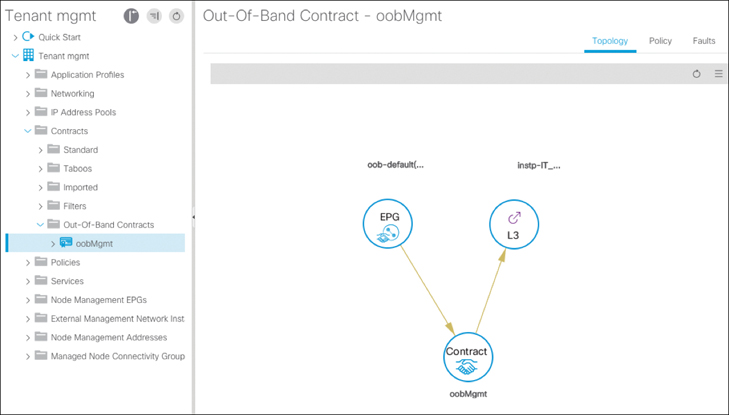
Figure 15-5 oobMgmt Contract Relationship
The next step is to test with the switches. You try using SSH to access a switch from your laptop, and the connection fails. Next, you try using SSH to access your management workstation behind the 10.254.10.0/24 subnet and confirm that it works. So far, you’ve confirmed that the out-of-band contract appears to be working for only the switches but not the APIC. Now you have to determine what is different between your switches and your APIC when it comes to the management EPG. To gain more insight, you right-click on the management EPG and select Show Usage. The screen that appears (see Figure 15-6), shows only switches.

Figure 15-6 Verifying Policy Usage for the oobMgmt Contract
Why are only switches, and not any of the APICs, in the management EPG? Where are devices placed into a management EPG? This is the node management address configuration. Under Static Node Management Addresses, you’ve defined the IP address for switches to use and what EPG this IP address belongs to. However, this was never done for the APICs. Therefore, the object model doesn’t have the IP configuration of the APIC. The IP configuration was only done during the initial setup wizard, when the underlaying OS was configured, not when the management information tree for ACI was created.
Solution
After you add your APIC to the static node management addresses, the policy model is complete, and an iptables configuration can be created and configured on the APICs to block incoming connections on ports that aren’t permitted and from sources that aren’t allowed. The configuration for APIC 1 is illustrated in Figure 15-7.
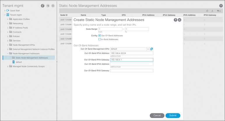
Figure 15-7 Assigning an Out-of-Band IP Address to APIC 1
Troubleshooting Contracts: Traffic Not Traversing a Firewall as Expected
You have a AAA server in tenant Shared-Service, and a resource in tenant ACI-AMT-Book needs access to it. The requirement is that this traffic must flow through a firewall that is connected to the core. To accomplish this, you provide an existing contract called AAA_Server from the AAA EPG in tenant Shared-Service. To reach the server in tenant ACI-AMT-Book, traffic should go out an L3Out in tenant Shared-Service, get routed to the firewall, and come back in the target VRF instance, ACI-AMT-Book:v1. Due to the traffic flow, the core L3Out in tenant ACI-AMT-Book will be providing the contract AAA_Server, and the Web EPG will be consuming it. Figure 15-8 illustrates the topology used.

Figure 15-8 Topology for the Firewall
You run a few tests and confirm that 172.16.0.10 can access 172.18.4.20. When you review the firewall logs, you see no traffic flow logs. Contract AAA_Server was defined in tenant Common, so to view the contract topology map, you navigate there. Here you confirm that in tenant Shared-Service, EPG AAA_Server is providing contract AAA_Server, and Shared-Service-L3OutCore is consuming it. In tenant ACI-AMT-Book, Internal-Net is providing the contract, and EPG App is consuming it. This is validated in the UI, as shown in Figure 15-9.
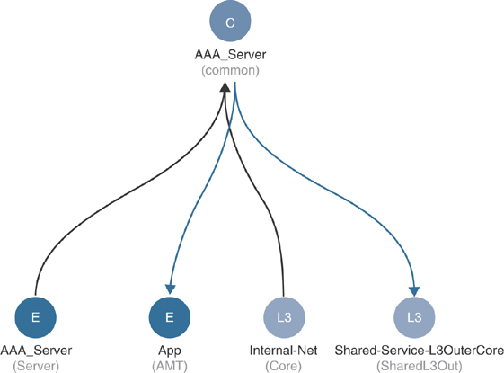
Figure 15-9 Contract Relationships for Contract AAA_Server
Here you confirm that in tenant Shared-Service, EPG AAA_Server is providing contract AAA_Server, and Shared-Service-L3OutCore is consuming it. In tenant ACI-AMT-Book, Internal-Net is providing the contract, and EPG App is consuming it.
The next stop should be to confirm the routing table, either in software or by using the ELAM app, to see where the packet is going. When running the show ip route command (see Example 15-6), you notice that there is a pervasive route pointing to the spine proxy. These routes are only pushed by the APIC when policy exists that requires the specific route.
Example 15-6 Routing Table of Leaf 103 with a Pervasive Route Pointing to the Spine Proxy
leaf103# show ip route vrf ACI-AMT-Book:v1 172.18.4.0
IP Route Table for VRF "ACI-AMT-Book:v1"
'*' denotes best ucast next-hop
'**' denotes best mcast next-hop
'[x/y]' denotes [preference/metric]
'%<string>' in via output denotes VRF <string>
172.18.4.0/24, ubest/mbest: 1/0, attached, direct, pervasive
    *via 10.0.184.66%overlay-1, [1/0], 00:39:26, static, tag 4294967294
         recursive next hop: 10.0.184.66/32%overlay-1
Solution
By taking a closer look at the policy of the contact, you can see that the scope is incorrectly set, as shown in Figure 15-10. Contracts where the scope is set to Global or Tenant can actually leak a route between two VRF instances and cause unexpected traffic flows.
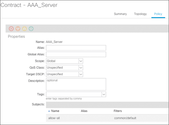
Figure 15-10 Contract Configuration for Contract AAA_Server
When using contracts from tenant Common, be sure to confirm that the scope is properly set to avoid causing an unexpected traffic path. In this case, the existence of a global contract allows the potential for leaking routes directly instead of having the traffic traverse VRF instances via the external firewall.
Troubleshooting Contracts: Contract Directionality
You’ve created a new EPG called JumpBox, which you use to connect (using SSH) to different servers. In some cases, you need to use SCP to copy files from the jump server to other servers in the VRF instance. Because of this requirement, you’ve decided to use the VRF EPG to provide a contract using port 22. This is often referred to as a vzAny contract, based on the object name. In the GUI, the folder is called EPG Collection for the VRF, as shown in Figure 15-11. The contract you create has a single subject called TCP:22, and you select Apply Both Directions because you also want to be able to copy files (using SCP) from the JumpBox to other devices. To allow the return traffic to work as well, you select Reverse Filter Ports.

Figure 15-11 Contract Provided on the VRF Instance
Contract TCP:22 is consumed on your new EPG called JumpBox. You go to the jump server and open an SCP session to the web server. This works as expected. From the web server, you now try to copy an updated package from the jump server by initiating an SCP session from the web server to the EPG JumpBox. The session times out. When you navigate to the Tenant tab to look for contract drops, you see that the flow in question is being dropped, as shown in Figure 15-12.

Figure 15-12 Contract Drops in the Tenant Operational View
To further look into this, you log on to the switch CLI to look at the zoning rules. To begin troubleshooting, you check the PCTag assigned to EPG JumpBox, which is 16394. You need to understand why the JumpBox EPG can use SSH to reach the web server.
In Example 15-7 you can see that EPG JumpBox (PCTag 16394) can talk to any EPG (PCTag 0) where the flow matches Filter 19. Filter 19 is what was defined on the APIC to allow destination port 22.
Example 15-7 Contract Deployment on Leaf 101 for Traffic Sourced from the JumpBox EPG
leaf101# show zoning-rule scope 2785280 src-epg 16394
Rule ID    SrcEPG DstEPG  FilterID operSt  Scope    Action     Priority
=======    ====== ======  ======== ======= =======  =======    ========
4158       16394  0       19        enabled 2981888  permit     fully_qual(6)
leaf101# show zoning-filter filter 19
<Snipped for Formatting>
FilterId  Name  EtherT  SFromPort     SToPort      DFromPort    DToPort
========= ====  ======  ===========   ===========  ===========  ===========
19        19_0  ip      unspecified   unspecified  22           22
In the reverse direction, PCTag 0 or any EPG is able to communicate with EPG JumpBox (PCTag 16394) but using a different filter, Filter 20, as shown in Example 15-8.
Example 15-8 Contract Deployment on Leaf 101 for Traffic Destined to the JumpBox EPG
leaf101# show zoning-rule scope 2785280 dst-epg 16394
Rule ID    SrcEPG DstEPG  FilterID operSt  Scope    Action     Priority
=======    ====== ======  ======== ======= =======  =======    ========
4151       0      16394   19        enabled 2981888  permit     fully_qual(6)
leaf101# show zoning-filter filter 19
<Snipped for Formatting>
FilterId  Name  EtherT  SFromPort     SToPort      DFromPort    DToPort
========= ====  ======  ===========   ===========  ===========  ===========
20        20_0  ip       22           22            unspecified   unspecified
Filter 20 just allows source port 22 with any destination port. This is the return traffic of the original traffic flow from EPG JumpBox to EPG Web. To better understand what happens when using Apply Both Directions and Reverse Filter Ports in hardware, examine Figures 15-13, 15-14, and 15-15.

Figure 15-13 Policy Enforcement Without Apply Both Directions and Reverse Filter Ports
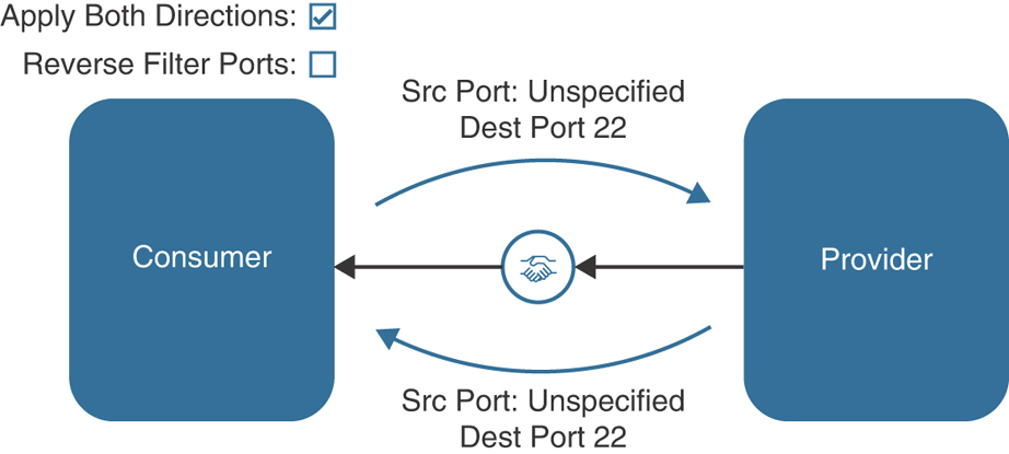
Figure 15-14 Policy Enforcement With Apply Both Directions and Without Reverse Filter Ports

Figure 15-15 Policy Enforcement with Apply Both Directions and Reverse Filter Ports
Because of the configuration, no EPG in the VRF instance is able to initiate an SCP connection with the JumpBox EPG because there is not a contract in place that allows this source and destination (sourced from unspecified and destined to port 22).
Solution
In order to enable anything in the VRF instance to initiate an SCP connection back to the JumpBox EPG, one of two configurations can be deployed:
Have both vzAny and the JumpBox EPG provide and consume the contract. With vzAny, this is suboptimal because now any EPG can use SSH or SCP to connect to any other EPG in the VRF instance. Providing and consuming the same contract is a better solution when using regular EPGs and not vzAny.
Add an additional filter entry to the subject where the source port is 22 and the destination port is unspecified. This allows flow opposite the intended direction.
After adding an additional filter entry, as described in the second option, initiating SCP connections to the JumpServer EPG works as intended.
Troubleshooting End Host Connectivity: Layer 2 Traffic Flow Through ACI
The server team has added a new web server to allow for the web cluster to expand. After connecting the machine to the ACI fabric, the server team is unable to communicate with the other server. The team claims that if they initiate a ping to Host A from Host B, the ping times out. This is the first server added to the ACI fabric, as the other server connects to an external switch, which then connects to ACI. After collecting the IP and MAC address information from the server, you are ready to begin troubleshooting, using the topology shown in Figure 15-16.

Figure 15-16 Layer 2 Connectivity for Web Servers
Before connecting the server, you provision a new EPG called Web and a bridge domain called Web. The bridge domain has been configured with the following default settings:
Unicast Routing: Enabled
Subnet Configured: No
L2 Unknown Unicast: Proxy
ARP Optimization: Enabled
Limit IP Learning to Subnet: Enabled
Under the EPG, two static path bindings have been added to allow communication to the server as well as the external switch. These bindings have VLAN 10 set to trunk. Because you know you are supposed to have VLAN 10 trunked correctly down to the two locations, the first step would be to validate that the VLAN is correctly programmed on the switch. Example 15-9 demonstrates how to check whether the VLAN is correctly deployed on Leafs 101 and 102.
Example 15-9 VLAN Deployment on Leafs 101 and 102
leaf101# show vlan extended

 VLAN Name                             Encap            Ports
 ---- -------------------------------- ---------------- -------------------
 16   ACI-AMT-Book:Web                 vxlan-16154554   Eth1/5, Po1
 17   ACI-AMT-Book:AMT:Web             vlan-10          Eth1/5, Po1

leaf102# show vlan extended
 VLAN Name                             Encap            Ports
 ---- -------------------------------- ---------------- ------------------
 16   ACI-AMT-Book:Web                 vxlan-16154554   Eth1/5, Po1
 17   ACI-AMT-Book:AMT:Web             vlan-10          Eth1/5, Po1
The output shows that the VLAN is correctly deployed, so now you can further validate that Host A’s MAC address is learned as an endpoint on Leafs 101 and 102, as shown in Example 15-10.
Example 15-10 Layer 2 Endpoint Verification on Leafs 101 and 102
leaf101# show endpoint mac 88f0.3187.3827
Legend:
 s - arp              O - peer-attached a - local-aged       S - static
 V - vpc-attached     p - peer-aged M - span             L - local
 B - bounce           H - vtep
+-------------------+---------------+-----------------+--------------+-------------+
      VLAN/           Encap          MAC Address       MAC Info/      Interface
      Domain          VLAN           IP Address        IP Info
+-------------------+---------------+-----------------+--------------+-------------+
17/ACI-AMT-Book:v1    vlan-10         88f0.3187.3827    LV            po1

leaf102# show endpoint mac 88f0.3187.3827
Legend:
 s - arp              O - peer-attached a - local-aged       S - static
 V - vpc-attached     p - peer-aged M - span             L - local
 B - bounce           H - vtep
+-------------------+---------------+-----------------+--------------+-------------+
      VLAN/           Encap          MAC Address       MAC Info/      Interface
      Domain          VLAN           IP Address        IP Info
+-------------------+---------------+-----------------+--------------+-------------+
17/ACI-AMT-Book:v1    vlan-10         88f0.3187.3827    LV            po1
With the VLAN deployed correctly and the endpoint learned on Leafs 101 and 102, the next step would be to check Leaf 103 to ensure that the same applies for Host B. When you check the VLAN deployment on Leaf 103, you notice that the VLAN is missing. If you think the configuration is correct, but it is not being deployed, you should check the EPG to see if there are any faults. If you navigate to Web EPG > Faults, you see a fault raised for the path on Leaf 103, as shown in Figure 15-17.

Figure 15-17 Fault Raised on EPG Web
Solution
As described in Chapter 5, “End Host and Network Connectivity,” for a VLAN to be successfully deployed to an interface, the port you are deploying needs to tie back to a domain. That domain references a VLAN pool that contains one or more VLANs that you wish to deploy on an interface. The error shown in Figure 15-17 explains that the domain you have associated to the EPG does not map back to the interface you have deployed; therefore, the VLAN cannot be configured on this port.
The Troubleshooting tab for the fault can be very useful if you think the configuration was set up correctly. The Troubleshooting tab allows you to look at all changes that were made within a certain time of the fault being raised. If you view it in this case, you see that the attachable access entity profile (AAEP) that was used to associate the domain to the interface was removed, as shown in Figure 15-18.

Figure 15-18 Troubleshooting Tab for a Fault Raised on EPG Web
By correcting the configuration as shown in Figure 15-19 and adding the correct AAEP to the interface policy group for the web server, you can see that the fault clears, and the VLAN is successfully pushed to the leaf. This configuration associates the AAEP WebServers, which contains the proper domain (AMT), with the interface policy group for WebServers.

Figure 15-19 AAEP Configuration for EPG WebServers
You can now also validate that the endpoint is being learned correctly on Leaf 103, as shown in Example 15-11.
Example 15-11 VLAN and Endpoint Verification for EPG WebServers on Leaf 103
leaf103# show vlan extended
 VLAN Name                             Encap Ports
 ---- -------------------------------- ---------------- ------------------------
 17   ACI-AMT-Book:BD1                 vxlan-16547722 Eth1/9
 18   ACI-AMT-Book:AMT:EPG1            vlan-2 Eth1/9
 25   ACI-AMT-Book:Web                 vxlan-16154554 Eth1/27
 27   ACI-AMT-Book:AMT:Web             vlan-10 Eth1/27

leaf103# show endpoint mac 0050.5682.4d40
Legend:
 s - arp              O - peer-attached a - local-aged       S - static
 V - vpc-attached     p - peer-aged M - span             L - local
 B - bounce           H - vtep
+-------------------+---------------+-----------------+--------------+-------------+
      VLAN/           Encap          MAC Address       MAC Info/      Interface
      Domain          VLAN           IP Address        IP Info
+-------------------+---------------+-----------------+--------------+-------------+
27/ACI-AMT-Book:v1   vlan-10          0050.5682.4d40     L             eth1/27
With the configuration corrected, you are confident that the servers will be able to communicate the access policy configuration because the end host connectivity has been resolved.
Troubleshooting External Layer 2 Connectivity: Broken Layer 2 Traffic Flow Through ACI
Despite resolving the fault described in the previous example and correcting the access policy configuration for the server on Leaf 103, the server team is still reporting connectivity issues between the servers. In order to further check what might be happening, you should choose a direction to focus on and validate what the expected packet flow should look like. Because the server team is unable to ping from Host B to Host A, you look to see if Leaf 103 knows where Host A exists. If you check the endpoint database on Leaf 103, you see that it has not learned the MAC address of Host A, as shown in Example 15-12.
Example 15-12 Host A MAC Address Is Not Learned on Leaf 103
leaf103# show endpoint mac 88f0.3187.3827
Legend:
 s - arp              H - vtep V - vpc-attached     p - peer-aged
 R - peer-attached-rl B - bounce           S - static M - span
 D - bounce-to-proxy  O - peer-attached a - local-aged       L - local
+-------------------+---------------+-----------------+--------------+-------------+
      VLAN/           Encap          MAC Address       MAC Info/      Interface
      Domain          VLAN           IP Address        IP Info
+-------------------+---------------+-----------------+--------------+-------------+
<EMPTY>
In this situation, the switch forwards packets based on the settings configured under the bridge domain. The server team also lets you know that it is unable to resolve ARP to Host A, which it feels is the reason that communication is unsuccessful. With ARP optimization enabled, an ACI leaf forwards ARP frames based on the target IP address in the ARP payload. If the ACI leaf does not know where the IP address of the endpoint exists, it forwards the frame to the IPv4 anycast proxy on either of the spine switches in the pod. However, because Limit IP Learning to Subnet is enabled but there is no subnet defined, the leafs do not learn IP address information for endpoints connected in the bridge domain. Therefore, the spine does not know where to redirect the ARP frame, and a glean cannot be generated by the leaf switches because there is no subnet for which to originate the glean. As a result, the frame is dropped in the ACI fabric. The same would go for unknown unicast traffic as well. If the ACI leaf switch does not know the destination MAC address, by default it sends the frame to the MAC proxy TEP on the spines in the pod. If the host times out or goes silent, the spine does not know of its existence, and the frame is dropped.
Solution 1
When connecting Layer 2 devices in ACI, best practice dictates setting L2 Unknown Unicast to Flood and enabling the ARP Flooding setting, as shown in Figure 15-20. These settings ensure that in situations where a leaf switch has not learned the remote endpoint, traffic can be flooded on the bridge domain, where it will reach the egress leaf(s) and be sent out.
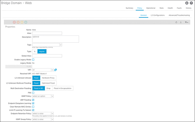
Figure 15-20 Web BD Should Use L2 Unknown Unicast Flooding and ARP Flooding
With these settings, the Layer 2 configuration now provides flooding of ARP frames, and the server team is able to communicate with Host A.
Solution 2
Another solution in this scenario would be to add a subnet under the BD. If the intention is to have the gateway on ACI, then this would be required to allow traffic to be routed. If the intention is to have the gateway configured on the external device, an additional IP address in the subnet needs to be allocated to the bridge domain. With the addition of the subnet under ACI, the ACI leaf switches can learn IP address information if it matches the given subnet range, and the leaf can perform host refresh and glean to detect whether hosts are still alive. This resolves the silent host issue if the host is still connected to the network but may not be sending traffic into the ACI fabric. You’ve decided to add a subnet under the bridge domain to resolve the issue because the intention is to move the routing functionality to ACI in the future.
Troubleshooting External Layer 3 Connectivity: Broken Layer 3 Traffic Flow Through ACI
Now that Layer 2 connectivity is working the way you want for the web servers, a requirement comes in that you need connectivity between web servers and some application servers that the server team is building. For these app servers, the subnet has not been provisioned yet, so the decision is to create the subnet on ACI and have ACI perform the routing functionality for these servers. An L3Out has been provisioned to statically route traffic to the external switch, where it can be sent back into the fabric for any EPGs where the gateway still resides externally. The topology for this flow is illustrated in Figure 15-21.
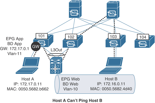
Figure 15-21 Layer 3 Connectivity for App and Web Servers
In addition, a contract has been configured that allows the necessary communication between the App EPG and the L3Out, which includes ICMP. After setting this up, the server team notifies you that the app server Host A is not able to ping the web server Host B. The team is, however, able to ping the gateway configured in BD App. You need to investigate what is causing the issue.
In this case, Host A is single attached to Leaf 101, so you can begin focusing on Leaf 101. Because the server team has let you know that it can ping the default gateway but not Host B, you need to validate that the route programming looks okay. Example 15-13 demonstrates how to check the routing table on Leaf 101.
Example 15-13 Routing Table for Route to Host B on Leaf 101
leaf101# show ip route 172.16.0.11 vrf ACI-AMT-Book:v1
IP Route Table for VRF "ACI-AMT-Book:v1"
'*' denotes best ucast next-hop
'**' denotes best mcast next-hop
'[x/y]' denotes [preference/metric]
'%<string>' in via output denotes VRF <string>
0.0.0.0/0, ubest/mbest: 1/0
    *via 10.10.100.3, vlan17, [1/0], 00:03:45, static
This looks good. From a routing table perspective, the leaf thinks it should route traffic destined to Host B by using the static default route configured under the L3Out. But even with the route present, the traffic does not work.
If you think back to Chapter 12, “Bits and Bytes of ACI Forwarding,” where you learned about the different forwarding paradigms, you know that an ACI leaf does a Layer 3 lookup as follows in the VRF instance in which the frame is received:
If the destination IP address is a learned endpoint, the frame is forwarded based on how that endpoint is learned.
If no endpoint is learned, the frame is forwarded based on the longest prefix matched route for that destination.
Because you know the route looks okay, you check whether you have learned the destination IP address as an endpoint, as shown in Example 15-14.
Example 15-14 Remote Endpoint Learned for Host B on Leaf 101
leaf101# show system internal epm endpoint ip 172.16.0.11
MAC : 0000.0000.0000 ::: Num IPs : 1
IP# 0 : 172.16.0.11 ::: IP# 0 flags :
Vlan id : 0 ::: Vlan vnid : 0 ::: VRF name : ACI-AMT-Book:v1
BD vnid : 0 ::: VRF vnid : 2981888
Phy If : 0 ::: Tunnel If : 0x18010003
Interface : Tunnel3
Flags : 0x80004400 ::: sclass : 49154 ::: Ref count : 3
EP Create Timestamp : 07/19/2018 20:02:06.034819
EP Update Timestamp : 07/19/2018 20:07:41.469567
EP Flags : IP|sclass|timer|
::::
You see that you have learned the destination IP address as an endpoint. Why would Leaf 101 have learned this endpoint? This endpoint should only be Layer 2 connected to ACI, as per the earlier requirements. You go back to the previous section, where you configured Layer 2 connectivity for Host B in EPG Web. You decided to leave unicast routing enabled on BD Web, and added a subnet to perform host refresh. As you know, when unicast routing is enabled, leaf switches learn the IP addresses of endpoints connected in that bridge domain. This also applies for remote endpoint learning, and as endpoints start being learned remotely, the leaf switches always prefer the tunnel where the endpoint is learned versus routing externally.
The design for this traffic flow only requires a contract between the App EPG and the L3Out, and because you did not add a contract between the App EPG and the Web EPG directly, this traffic is not allowed.
Upon further inspection, you notice that there are drops incrementing under the tenant for this flow, so you know the traffic is being dropped because there is no contract that permits this traffic. You can see this by selecting Tenant > Operational > Flows > L3 Drop, as shown in Figure 15-22.
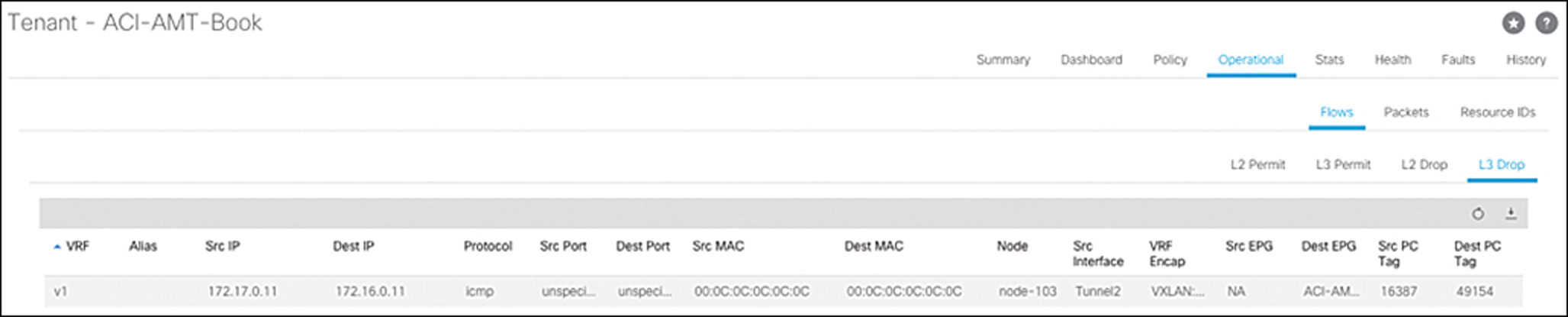
Figure 15-22 Layer 3 Drop Statistics for Tenant ACI-AMT-Book
Solution
In order to resolve this issue, you need to review your design for the Layer 2 flow. You had two options to enable Layer 2 connectivity between the two web servers:
Disable unicast routing and enable ARP flooding and L2 unknown unicast flooding.
Enable routing and add a subnet to allow for host refreshing and glean.
With the current design, you need to ensure that traffic is sent via the L3Out, so you cannot have the fabric learn IP address information for the servers in EPG Web since you have not moved the gateway for the Web EPG into ACI yet. In order to prevent IP learning in EPG Web, you need to revert to the first option.
After disabling unicast routing and changing to ARP flooding and L2 unknown unicast flooding, the server team tells you that Host A in EPG App is able to communicate with Host B in EPG Web.
Troubleshooting External Layer 3 Connectivity: Unexpected Layer 3 Traffic Flow Through ACI
You now have a new requirement for the ACI network. The developers need to be able to access the app servers so they can test code and push changes when new vulnerabilities are detected. Developers connect to the network using a different external router than the production external traffic. Because of this, you have configured a new L3Out and assigned the interfaces connecting to the dev external router. The topology in Figure 15-23 is used as reference.

Figure 15-23 Layer 3 Connectivity for App Servers and Dev Server
The security team is very strict about what traffic is allowed through the development environment. The team needs the ACI fabric to only allow the specific ports for the application between EPG App and the L3Out toward the dev server. After setting up the new dev L3Out and adding a contract that only allows the ports for the application, the security team calls and says it is able to ping the app servers from the dev network. They need this to be resolved immediately. You need to look at why ICMP is allowed between the App EPG and the L3Out for the dev network, despite the contract in place that only allows particular TCP ports.
In this case, it’s important to remember how contracts are programmed in regard to L3Outs. Under an L3Out, contracts are configured via external EPGs, where one or more subnets are defined along with one or more contracts. As frames enter the L3Out, policy is enforced based on the prefix that is matched for the external EPG. Because you are applying policy based on IP address, the match occurs for a prefix globally in a VRF instance.
These rules are controlled by the NX-OS process ACLQOS. When a user configures an external EPG and defines prefixes within it, the APIC pushes this configuration to the leaf. The configuration is then pushed into hardware by ACLQOS. Each prefix is assigned the PCTag for the external EPG so that contracts can be applied matching the prefix and, thus, the tag. You can view the prefix configuration for a given VRF instance by finding the VXLAN VNID (segment) for the VRF instance and checking ACLQOS for that VNID, as shown in Figure 15-24 and Example 15-15.

Figure 15-24 VNID for VRF Instance v1 Within Tenant ACI-AMT-BOOK
Example 15-15 IP Prefix Verification Within ACLQOS for a Given VRF Instance on Leaf 101
leaf101# vsh -c "show system internal policy-mgr prefix" | egrep "Vrf|=|2981888"
Vrf-Vni VRF-Id Table-Id   Table-State  VRF-Name      Addr       Class  Shared Remote
  Complete
======= ====== ========== =========== ============= =========== =====  ====== ======
  ========
2981888 6      0x80000005 Up          ACI-AMT-Book:v1     0::/0   15   False  False
  False
2981888 6      0x5        Up          ACI-AMT-Book:v1 0.0.0.0/0   15   False  False
  False
In this case, you can see that only the “any” prefix 0.0.0.0/0 has been configured. This is indeed what has been configured, but what is different is the class or PCTag that has been assigned to this route: 15, or 0xf. This doesn’t seem to match what has been allocated for the external EPG defined under the dev L3Out, as shown in Figure 15-25.

Figure 15-25 The PCTag for an External EPG in the Cisco APIC UI
In this case, you would expect the subnet (0.0.0.0/0) to get associated with PCTag 16389. However, there is one exception to how prefixes get assigned to the corresponding external EPG PCTag: the all-zeros prefix.
The all-zeros prefix is always allocated the dedicated prefix 15 (0xf) globally within the VRF instance. This means that if any other L3Out that also uses the all-zeros prefix has contracts to an EPG, traffic can be classified using that contract.
In the previous example, you needed to define a contract between the App EPG and the L3Outfor External-Net. This contract was required to allow traffic to be routed outside the ACI fabric for connectivity to the web servers. The L3Out for External-Net was also configured with an all-zeros prefix, and the common/default contract was used to allow all traffic toward the App EPG as it came in the L3Out from the external network. Because the all-zeros prefix was defined under multiple L3Outs, traffic is also being classified for the dev L3Out. This is because both L3Outs reside within the same VRF instance, and the prefix 100.100.100.100 falls within 0.0.0.0/0.
You can further validate the filter the switch will use when enforcing policy between the App EPG and the VRF instance with the PCTag 15. You do this by checking the zoning-rules on the leaf from iBash, as shown in Example 15-16.
Example 15-16 Contract and Filter Verification for PCTag 15 on Leaf 101
leaf101# show zoning-rule scope 2981888 dst-epg 15
Rule ID    SrcEPG DstEPG  FilterID operSt  Scope    Action     Priority
=======    ====== ======  ======== ======= =======  =======    ========
4109       0      15      implicit enabled 2981888  deny,log   any_vrf_any_deny(21)
4117       16387  15      default  enabled 2981888  permit     src_dst_any(8)
As you can see, all traffic is allowed to communicate between the App EPG (PCTag 16387) and any prefix that falls under the all-zeros prefix defined in the VRF instance using the default filter.
Solution
Under a given VRF instance, it is best practice to only define the all-zeros route under one L3Out to prevent traffic from being classified incorrectly. In order to resolve this, you need to remove the all-zeros prefix from the external EPG for development and add a more specific prefix to classify the traffic you want to enforce, as shown in Figure 15-26.
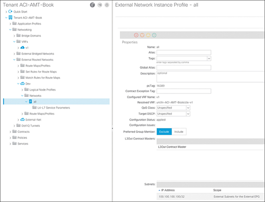
Figure 15-26 Adding a More Specific Prefix to the External EPG for Development
After doing this, you now see in ACLQOS that the prefix is directly identified with the PCTag of the external EPG for development, as shown in Example 15-17.
Example 15-17 Adding a More Specific Prefix to the External EPG for Development
leaf101# vsh -c "show system internal policy-mgr prefix" | egrep "Vrf|=|2981888"
Vrf-Vni VRF-Id Table-Id Table-State  VRF-Name      Addr    Class  Shared Remote
  Complete
=======  === ========== ==  =============     ============= ====  ==== =====
  ========
2981888  6   0x80000005 Up  ACI-AMT-Book:v1       0::/0        15    False  False
  False
2981888  6   0x5        Up  ACI-AMT-Book:v1       0.0.0.0/0    15    False  False
  False
2981888  6   0x5        Up  ACI-AMT-Book:v1 100.100.100.100/32  16389 False False
  False
With this in place, any traffic coming from 100.100.100.100 in that VRF instance is classified using the contract configured under the external EPG for development, which only allows the TCP ports needed for the app servers. You can re-validate the zoning rules on the switch, as shown in Example 15-18.
Example 15-18 Contract and Filter Verification for PCTag 16389 on Leaf 101
leaf101# show zoning-rule scope 2981888 dst-epg 16387
Rule ID    SrcEPG DstEPG  FilterID operSt  Scope    Action     Priority
=======    ====== ======  ======== ======= =======  =======    ========
4121       16389  16387   8        enabled 2981888  permit     fully_qual(6)

leaf101# show zoning-filter filter 8
<Snipped for Formatting>
FilterId  Name  EtherT  SFromPort     SToPort      DFromPort    DToPort
========= ====  ======  ===========   ===========  ===========  ===========
8         8_0   ip      unspecified   unspecified  3260         3260
With this configuration in place, the security team makes you aware that all other traffic is denied from the development network and that it can only connect to the App EPG on port 3260 via the development L3Out.
Troubleshooting Leaf and Spine Connectivity: Leaf Issue
Your manager has asked you to troubleshoot an application outage. It’s a three-tier application, and users are not able to connect to the front-end web server. You review the network topology where the application is hosted using the ACI fabric (see Figure 15-27).
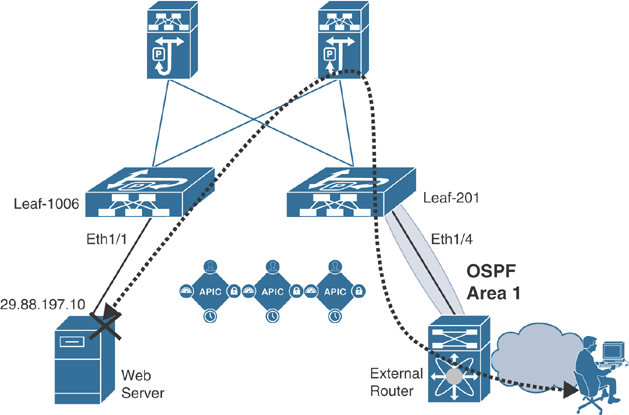
Figure 15-27 Network Topology Hosting Application
Solution
To begin troubleshooting the issue, first you should get the IP address of the unreachable web server (in this example, 29.88.197.10). Take this IP address and check to see if the endpoint IP address is learned in ACI. In order to do this in the APIC GUI, go to Operations tab > EP Tracker. Type the IP address of the web server in the search bar and press Enter. Figure 15-28 shows the output.
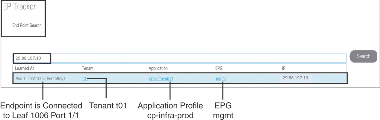
Figure 15-28 Checking Endpoint Learning in ACI
You know now that the endpoint is learned in ACI, and the web server is active. Use SSH to access Leaf 1006 to verify that the encapsulation VLAN and anycast gateway are programmed on the switch, as shown in Example 15-19.
Example 15-19 VLAN and Anycast Gateway Deployment on Leaf 1006
Leaf-1006# show vlan extended

 VLAN Name                             Encap            Ports
 ---- -------------------------------- ---------------- ------------------------
 28   t01:a-cp-infra-mgmt              vxlan-15335344   Eth1/1, Eth1/5, Eth1/6,
                                                        Eth1/7, Eth1/8, Po1, Po3
 29   t01:cp-infra-prod:mgmt           vlan-1001        Eth1/1, Eth1/5, Eth1/6,
                                                        Eth1/7, Eth1/8, Po1, Po3

Leaf-1006# show ip interface brief vrf t01:standard
IP Interface Status for VRF "t01:standard"(5)
Interface            Address              Interface Status
vlan28               29.88.197.1/27       protocol-up/link-up/admin-up
Now check the reachability of the web server from the directly connected leaf:
Leaf-1006# iping 29.88.197.10 -V t01:standard
PING 29.88.197.10 (29.88.197.10): 56 data bytes
64 bytes from 29.88.197.10: icmp_seq=0 ttl=63 time=0.756 ms
64 bytes from 29.88.197.10: icmp_seq=1 ttl=63 time=0.375 ms
64 bytes from 29.88.197.10: icmp_seq=2 ttl=63 time=0.551 ms
^C
--- 29.88.197.10 ping statistics ---
3 packets transmitted, 3 packets received, 0.00% packet loss
round-trip min/avg/max = 0.375/0.56/0.756 ms
You are now sure that there is nothing wrong with web server reachability from the directly connected Leaf 1006. Because the users are accessing the web server from a remote network external to the ACI fabric, you should now check the connectivity from Border Leaf 201 toward the external router, as shown in Example 15-20.
Example 15-20 OSPF Neighbor Verification on Leaf 201
Leaf-201# show ip ospf neighbors vrf t01:standard
 OSPF Process ID default VRF t01:standard
 Total number of neighbors: 1
 Neighbor ID     Pri State            Up Time  Address         Interface
 39.88.193.129     1 FULL/ -          3w0d     49.88.192.26    Eth1/4
You have confirmed that the connectivity from Border Leaf 201 to the external router is fine. Next, you try to ping from Border Leaf 201 to the web server IP address, as shown in Example 15-21.
Example 15-21 iPing Failing to the Destination
Leaf-201# iping 29.88.197.10 -V t01:standard
PING 29.88.197.10 (29.88.197.10) from 49.88.192.27: 56 data bytes
Request 0 timed out
Request 1 timed out
Request 2 timed out
^C
--- 29.88.197.10 ping statistics ---
4 packets transmitted, 0 packets received, 100.00% packet loss
You are not able to ping from Border Leaf 201 to the web server that is plugged in to Leaf 1006. This means there is something wrong in the ACI fabric. You logged in to APIC GUI and checked the system faults. You found that Border Leaf 201 somehow became inactive in the fabric, as shown in Figure 15-29.
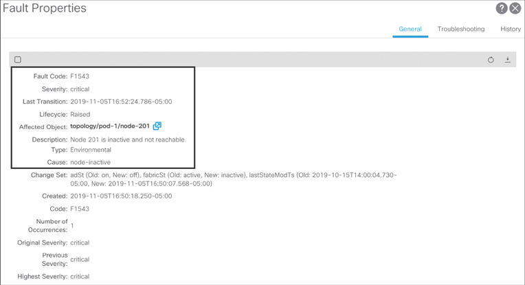
Figure 15-29 ACI Fault Showing Border Leaf 201 Becoming Inactive
As you further diagnose the Border Leaf 201 issue, you find that both of the uplinks toward the spines were down due to transceiver errors. You replace the transceivers and bring Border Leaf 201 back to active in the fabric, as shown in Example 15-22.
Example 15-22 Border Leaf 201 Back to Active State
APIC-1# acidiag fnvread
      ID   Pod ID                 Name    Serial Number         IP Address    Role
  State   LastUpdMsgId
-------------------------------------------------------------------------------------
  -------------------------
     101        1      Spine-101          FOX2120P68P       10.2.2.76/32   spine
  active   0
     102        1      Spine-102          FOX2126PD4S       10.2.2.77/32   spine
  active   0
     201        1      Leaf-201           FDO212225QJ      10.2.44.65/32    leaf
  active   0
    1006        1      Leaf-1006          FDO21460982       10.2.2.74/32    leaf
  active   0

Total 4 nodes
Now, if you try to reach the web server from Border Leaf 201, you should be able to do so, as shown in Example 15-23.
Example 15-23 Endpoint and Tunnel Verification on Border Leaf 201
Leaf-201# show endpoint ip 29.88.197.10
Legend:
 s - arp              H - vtep             V - vpc-attached     p - peer-aged
 R - peer-attached-rl B - bounce           S - static           M - span
 D - bounce-to-proxy  O - peer-attached    a - local-aged       L - local
+-----------------------------------+---------------+-----------------+-------------
  -+-------------+
      VLAN/                           Encap           MAC Address       MAC Info/
  Interface
      Domain                          VLAN            IP Address        IP Info
+-----------------------------------+---------------+-----------------+-------------
  -+-------------+
t01:standard                                             29.88.197.10
  tunnel25

Leaf-201# show interface tunnel 25
Tunnel25 is up
    MTU 9000 bytes, BW 0 Kbit
    Transport protocol is in VRF "overlay-1"
    Tunnel protocol/transport is ivxlan
    Tunnel source 10.2.44.65/32 (lo0)
    Tunnel destination 10.2.2.74
    Last clearing of "show interface" counters never
    Tx
    0 packets output, 1 minute output rate 0 packets/sec
    Rx
    0 packets input, 1 minute input rate 0 packets/sec

Leaf-201#
Leaf-201# acidiag fnvread | grep 10.2.44.65
     201        1      Leaf-201      FDO212225QJ      10.2.44.65/32    leaf
  active   0

Leaf-201#
Leaf-201# acidiag fnvread | grep 10.2.2.74
    1006        1      Leaf-1006     FDO21460982      10.2.2.74/32     leaf
  active   0

Leaf-201# iping 29.88.197.10 -V t01:standard
PING 29.88.197.10 (29.88.197.10): 56 data bytes
64 bytes from 29.88.197.10: icmp_seq=0 ttl=63 time=0.756 ms
64 bytes from 29.88.197.10: icmp_seq=1 ttl=63 time=0.375 ms
64 bytes from 29.88.197.10: icmp_seq=2 ttl=63 time=0.551 ms
^C
--- 29.88.197.10 ping statistics ---
3 packets transmitted, 3 packets received, 0.00% packet loss
round-trip min/avg/max = 0.365/0.46/0.654 ms
Note
This troubleshooting use case outlines various troubleshooting steps to resolve the issue. However, always remember that if a failure event occurs or someone has made any configuration change that could have destabilized the network, you can check the fault and audit logs to get clues right away.
Troubleshooting VMM Domains: VMM Controller Offline
The server team just installed a new VMware vSphere cluster to deploy production applications. You advise the team to plug the servers in to the ACI fabric so you can use VMM integration with the VMware vDS to help seamlessly map VMware port groups to EPGs in the ACI fabric. However, upon creating the VMM domain, the server administrators advise you that they do not see the vDS that was supposed to be pushed by APIC. When navigating to the VMM domain in the APIC UI, you see the fault shown in Figure 15-30.

Figure 15-30 A Fault Raised on the VMM Domain Stating That the APIC Can’t Connect to vCenter
The fault is alerting you that the APIC is unable to connect to vCenter, so it can’t pull the inventory and deploy the vDS. You need to check whether the APICs have IP connectivity to the configured vCenter. The APICs form a cluster, but only one APIC is responsible for handling the connection to a VMM domain at a time. This is known as the “shard leader” for a VMM domain. If the shard leader goes down, such as for an upgrade or a replacement, the connection is moved to another available APIC. Because you need to check network connectivity from the APIC to vCenter, you need to locate the shard leader for the VMM domain. This is done on the NX-OS CLI of any APIC by running the show vmware domain name VMM-domain command, as shown in Example 15-24.
Example 15-24 Viewing the VMM Domain Configuration and Checking the Shard Leader
apic1# show vmware domain name ACI-AMT-Book
Domain Name                        : ACI-AMT-Book
Virtual Switch Mode                : VMware Distributed Switch
Vlan Domain                        : ACI-AMT-Book (100-150)
Physical Interfaces                :
Number of EPGs                     : 0
Faults by Severity                 : 0, 1, 0, 1
LLDP override                      : no
CDP override                       : no
Channel Mode override              : no
NetFlow Exporter Policy            : no
vCenters:
Faults: Grouped by severity (Critical, Major, Minor, Warning)
vCenter               Type      Datacenter            Status    ESXs   VMs   Faults
--------------------  --------  --------------------  --------  -----  ----- ------
172.18.118.140        vCenter   ACI-AMT-Book          unknown   0      0     0,1,0,1

APIC Owner:
Controller    APIC      Ownership
------------  --------  ---------------
VC            apic-1     Leader
VC            apic-2     NonLeader
VC            apic-3     NonLeader

Trunk Portgroups:
Name                                           VLANs
---------------------------------------------  -------------------------------------
Here you can see that APIC 1 is the shard leader for the newly deployed VMM domain. While APIC 1 is online, all troubleshooting can be performed directly on APIC 1 because it performs the necessary functions for the VMM domain unless it goes offline. Next, you need to see if APIC 1 has IP connectivity to vCenter by initiating a ping, as shown in Example 15-25.
Example 15-25 Checking Shard Leader IP Connectivity to vCenter by Using ping
admin@apic1# ping 172.18.118.140
PING 172.18.118.140 (172.18.118.140) 56(84) bytes of data.
From 10.100.1.10 icmp_seq=1 Destination Host Unreachable
From 10.100.1.10 icmp_seq=2 Destination Host Unreachable
From 10.100.1.10 icmp_seq=3 Destination Host Unreachable
From 10.100.1.10 icmp_seq=4 Destination Host Unreachable
Here you can see that you are unable to ping vCenter. vCenter should be reachable via the OOB network, but the ping request was using the 10.100.1.10 address, which is configured for in-band. In order to see what the Linux routing table looks like on the APIC, you can run the route command from the bash CLI of APIC 1, as shown in Example 15-26.
Example 15-26 Checking the Routing Table of the APIC Shard Leader
apic1# bash
apic1:~> route
Kernel IP routing table
Destination     Gateway         Genmask         Flags Metric Ref    Use Iface
default         10.100.1.1      0.0.0.0         UG    8      0        0 bond0.10
default         192.168.4.1     0.0.0.0         UG    16     0        0 oobmgmt
10.0.0.0        10.0.0.30       255.255.0.0     UG    0      0        0 bond0.3091
10.0.0.30       0.0.0.0         255.255.255.255 UH    0      0        0 bond0.3091
10.0.168.65     10.0.0.30       255.255.255.255 UGH   0      0        0 bond0.3091
10.0.168.66     10.0.0.30       255.255.255.255 UGH   0      0        0 bond0.3091
10.100.1.0      0.0.0.0         255.255.255.0   U     0      0        0 bond0.10
10.100.1.1      0.0.0.0         255.255.255.255 UH    0      0        0 bond0.10
169.254.1.0     0.0.0.0         255.255.255.0   U     0      0        0 teplo-1
169.254.254.0   0.0.0.0         255.255.255.0   U     0      0        0 lxcbr0
172.17.0.0      0.0.0.0         255.255.0.0     U     0      0        0 docker0
192.168.4.0     0.0.0.0         255.255.255.0   U     0      0        0 oobmgmt
Here you see that there are two default routes: one via the in-band interface with a metric of 8, and the other via the out-of-band interface with a metric of 16. Because the in-band interface has a lower metric, that will be the interface used to reach any network outside of what is locally configured.
Solution 1
One solution is to provide network connectivity from the in-band interface of the APIC to vCenter.
Solution 2
Another solution is to change the default APIC connectivity preference to out-of-band versus in-band by navigating to System > System Settings > APIC Connectivity Preferences and selecting ooband.
Note
If other services, such as NTP and syslog, are intended to work using in-band, then you may need to change the configuration of each protocol to explicitly use the in-band EPG. This overwrites the default policy and uses the in-band interface for those protocols.
Troubleshooting VMM Domains: VM Connectivity Issue After Deploying the VMM Domain
Since resolving the previous issue, the APIC has successfully connected to vCenter and pushed a vDS. The server team has added the appropriate hosts behind a UCS B-Series blade chassis to the vDS. The current requirement is to push a port group to vCenter for the Web EPG so that new virtualized web servers can inherit the existing policy. However, after mapping the VMM domain to the Web EPG, the server administrators notify you that the VMs are unable to ping the gateway.
When the VMM domain was mapped to the EPG, both Deployment Immediacy and Resolution Immediacy were set to Immediate. To troubleshoot this issue, you navigate to Dynamic EPG Members to see if the VLAN was pushed to the interfaces that connect to the UCS fabric interconnects, but you do not see the paths listed. This means the VLAN that was dynamically allocated for this EPG is not being pushed to the switches and switchports where the UCS fabric interconnects connect.
When deploying using the On-Demand or Immediate setting, a valid LLDP or CDP adjacency must be reported from vCenter for the physical NICs on the host that is added to the APIC managed vDS. To troubleshoot this issue, you look at the faults raised under the VMM domain and notice that there is a fault for being unable to retrieve the adjacency information for a host where the VMs reside, as shown in Figure 15-31.

Figure 15-31 Fault for Missing Adjacency on the ESXi Host
Because the APIC is unable to retrieve the adjacency information from vCenter, it cannot deploy the dynamic configuration to the switches and ports where the UCS fabric interconnects are connected. Because the fabric interconnects terminate LLDP and CDP on the uplinks and downlinks, it’s critical that the UCS domain is configured to send LLDP or CDP, depending on what is desired. In this case, LLDP is configured in the vSwitch policy under the VMM domain. The ultimate goal is to ensure that the discovery protocol pushed to vCenter via the vSwitch policy matches what is being sent and received on the hosts.
Solution 1
The UCS server administrators should enable LLDP under the network control policy for the vNICs on the blades. Once it is enabled, LLDP can be sent and received, allowing the hosts to view a neighbor pointing to the fabric interconnect. The host can then communicate this to vCenter, and the APIC can receive the configuration in the form of an event.
Solution 2
If CDP is the desired protocol, ensure that it is enabled on the UCS domain and change the vSwitch policy so that LLDP is disabled and CDP is enabled. This way, you can push CDP as the discovery protocol on the vDS.
The APIC can then deploy the configuration to switches and ports where the fabric interconnects are connected, based on the neighbor information received from vCenter. Once there is a valid neighbor, the dynamic paths can be seen under Dynamic EPG Members for the EPG, as shown in Figure 15-32.
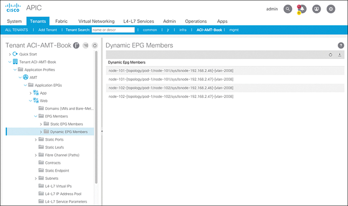
Figure 15-32 Verifying That Dynamic Paths Are Deployed to the Leafs Connecting to the Fabric Interconnects
If there are no paths shown in this UI, the adjacency cannot be resolved. This is just an additional way to verify that the correct state has been built in vCenter for the corresponding hosts.
Solution 3
If you don’t want the policy to rely on dynamic discovery using LLDP or CDP, you can set Resolution Immediacy on the VMM domain EPG mapping to Pre-Provision to ignore the adjacency requirement and push the VLAN to every switch and interface that is mapped to the AAEP used for the VMM domain. When using Pre-Provision, it is best practice to have a separate AAEP for VMM so that the VLAN is not pushed unnecessarily to interfaces connecting to bare-metal servers or devices providing external Layer 2 or Layer 3 connectivity.
Using either of the three offered solutions, the VLANs can be deployed properly, and the server administrators can notify you that the VMs have connectivity on the network.
Troubleshooting L4–L7: Deploying an L4–L7 Device
Due to business expansion, additional web servers have been deployed to handle the increased load. You decide to insert a policy-based routing (PBR) service graph to intercept traffic and redirect it to the load balancer before it reaches the new web servers. The first step is to connect the load balancer to the fabric so you can configure it directly by creating a static path on an EPG. After configuring the load balancer, you create the L4–L7 device and deploy the service graph template. After doing this, you notice that traffic isn’t hitting the load balancer as expected. Figure 15-33 illustrates the topology used.
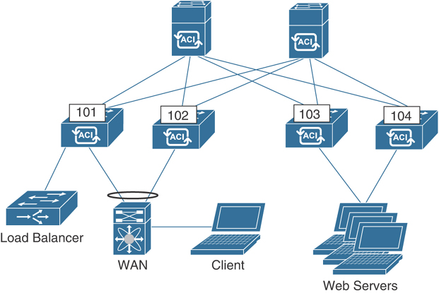
Figure 15-33 Load Balancer Inserted into Web Traffic Flow
To begin troubleshooting, you review the L4–L7 deployed graph instance and verify that the right VLANs are deployed on the Ethernet interfaces toward the load balancer. Figure 15-34 shows the view of the deployed service graph instance. You verify that the correct VLANs are configured: VLAN 15 for the outside and VLAN 5 for the inside. From the deployed graph instance, you also see the PCTag assigned to the VLANs. The L4–L7 deployed VLANs are also called shadow EPGs because they function like traditional EPGs but are controlled by the service graph.
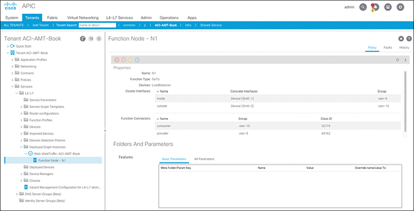
Figure 15-34 Deployed Service Graph Instance
A quick way to verify whether these VLANs are deployed is by checking the VLANs on the leaf node where the service device is connected. Example 15-27 shows the currently deployed VLANs.
Example 15-27 VLAN Verification on Leaf 101
leaf101# show vlan extended | egrep -A 1 "vlan-5 "
 1    ACI-AMT-                         vlan-5           Eth1/21
      Book:LoadBalancerctxv1:inside:
leaf101# show vlan extended | egrep -A 1 "vlan-15 "
 59   ACI-AMT-Book:NetCentric:VLAN15   vlan-15          Eth1/47
The VLAN name should always be Tenant:L4-L7DeviceName+VRF:ClusterInterfaceName. As you can see in Example 15-27, VLAN 5 is deployed properly, but ACI-AMT-Book:LoadBalancerctxv1:inside is deployed with VLAN 5, and VLAN 15 is deployed for an EPG named VLAN15 inside the NetCentric application profile. Based on this output, you determine that the graph did not get deployed properly. The next step should be to look at all faults raised. Given that you don’t know where the fault is raised, it is easiest to go to the top-level tenant view and view all faults for the tenant, as shown in Figure 15-35.

Figure 15-35 Faults Raised in a Tenant
Here you can see that fault F0467 is raised; the fault description says that encapsulation is already in use by ACI-AMT-Book:NetCentric:VLAN15. This confirms why VLAN 15 wasn’t properly deployed as a shadow EPG.
One common issue with service graphs is that the service device interfaces are part of a regular EPG—usually because IP connectivity is required to configure the service device. To resolve this issue, the old static path needs to be deleted so the shadow EPG can be deployed. After making this change, you see that PBR now works, but you are no longer able to use SSH to connect directly to the load balancer to make changes. This indicates a contract issue, and you can confirm it by looking at the packet log or the deny flows in the APIC UI. The service graph does not enable you to access devices inside the shadow EPG.
Solution
You can update the service graph template to allow Direct Connect, as shown in Figure 15-36. This way, you can create a contract relationship between the consumer or provider EPG and the corresponding shadow EPG.

Figure 15-36 Service Graph Direct Connect
Troubleshooting L4–L7: Control Protocols Stop Working After Service Graph Deployment
After deploying a new service graph between an EPG and vzAny in the VRF instance, you notice that some control plane protocols, such as CDP, LLDP, and LACP, stop functioning. Servers begin dropping because LACP keeps timing out, and you must move quickly to isolate the issue.
You start by reviewing how the service graph was deployed. The requirement was to have all traffic sourced from EPG untagged redirected to a firewall. In order to accommodate this, the service graph was deployed using the EPG as the consumer and vzAny as the provider, as shown in Figure 15-37.

Figure 15-37 Deployed Graph Instance for Service Graph
The EPG is named untagged because all servers inside this EPG also send traffic without an 802.1Q tag. Control protocols such as LACP also do not include a VLAN tag, so it’s possible that the leaf switch could classify these packets in the EPG where the untagged VLAN is deployed.
In order to troubleshoot the issue further, you run tcpdump on the kpm_inb interface on the leaf where the hosts connect, and you notice that no LACP frames are reaching the CPU, as shown in Example 15-28.
Example 15-28 tcpdump on kpm_inb Showing No LACP Packets Being Received
leaf101# tcpdump -xxvi kpm_inb ether proto 0x8809
tcpdump: listening on kpm_inb, link-type EN10MB (Ethernet), capture size 65535 bytes
You suspect that they might be redirected because of how the service graph is deployed. But how could control protocol frames like LACP frames be redirected? These frames are only Layer 2 and do not include a Layer 3 header, which is what you would expect the match criteria for redirection to be. You decide to take a closer look at the contract that was used to deploy the service graph; see Figure 15-38.

Figure 15-38 Contract Configuration for the Deployed Service Graph
Aha! The contract deployed is using the common/default filter, which matches on all frame types—not just packets with Layer 3 information. Because the service graph was deployed with vzAny as the provider, any packet that gets classified in EPG untagged is redirected to the firewall.
Solution
It was only desired to have traffic with an L3 header redirected to the firewall. In order to resolve the issue, you add a new filter to the contract to match only on IP traffic, as shown in Figure 15-39. You then remove the common/default filter from the contract.

Figure 15-39 IP-Only Filter to Redirect Only IP Packets to the Firewall
This way, Layer 2 control plane frames are forwarded to the CPU as normal; they are not redirected to the firewall.
Troubleshooting Multi-Pod: BUM Traffic Not Reaching Remote Pods
Your business is expanding to a new location. You want to extend your ACI fabric to that location to allow for easy integration with your existing environment, and you want a single pane of glass for both locations. You meet all the requirements for deploying multi-pod, so you decide to roll out the deployment by adding the new location as a second pod to your existing ACI fabric.
However, after you add the pod and connect servers at the new location in an existing bridge domain, you find that those servers cannot resolve ARP to servers if they are in different pods. Because servers can always resolve ARP to other servers in the same pod, you are confident that this is an issue with the multi-pod deployment. Figure 15-40 shows the BD stretched across multi-pod.

Figure 15-40 Bridge Domain Stretched Across Pod 1 and Pod 2
Because you know that only a single spine in each pod will join a group and send traffic for a group, you start by investigating which spine is authoritative for the bridge domain using Group IP outer (GIPo) 225.0.96.144. This can be accomplished by running the show isis internal mcast routes command on a spine iBash CLI and checking if there is an external interface for the route in question. You run the command on Spine 201 and get the output shown in Example 15-29.
Note
In this topology, interfaces Ethernet1/1 and Ethernet1/2 connect to the IPN(s), so running the command and using grep for four lines after the match is sufficient. If you had more interfaces connecting to the IPN, you would need to add more lines to the grep statement.
Example 15-29 Checking Spine 201 for a GIPo Route with External Interfaces
pod1-spine201# show isis internal mcast routes | grep -A 4 "225.0.96.144"
GIPo: 225.0.96.144 [TRANSIT]
    OIF List:
      Ethernet1/1.1(External)
      Ethernet1/5.83
      Ethernet1/6.84
Based on this, you know that Spine 201 is authoritative for the GIPo and that it is sending traffic for this group toward the IPN on interface Ethernet1/1. This interface connects to IPN1.
The next step would be to check the multicast routing table of the IPNs to ensure that the proper routes are in place to forward the traffic for group 225.0.96.144 between pods. Example 15-30 shows the output of the mroute table on IPN1.
Example 15-30 mroute Validation on IPN 1
IPN3# show ip mroute 225.0.96.144 vrf IPN
(*, 225.0.96.144/32), bidir, uptime: 00:00:26, igmp ip pim
  Incoming interface: Ethernet1/1.4, RPF nbr: 192.168.1.0
  Outgoing interface list: (count: 2)
      Ethernet1/1.4, uptime: 00:00:26, igmp, (RPF)
Here you see that the same interface is listed as incoming and outgoing. The incoming interface should be the interface facing the rendezvous point (RP), or if the RP is local, the incoming interface should be the interface facing the loopback interface where the RP is configured. In this case, the incoming interface is the link connecting to Spine 201 in Pod 1. The spines in ACI do not run PIM, so they are not valid RPFs for the route to the RP.
The IPN thinks the RP is via the spine because of the default OSPF cost. In this topology, the ACI spines are connected at 40 Gbps and have a default OSPF cost of 1. The interfaces between the IPNs are connected at 10 Gbps and have a higher cost due to the lower bandwidth. Because of this, the route to the RP is preferred through the ACI spines.
Solution 1
If the platform supports it, the interfaces between IPNs should have a matching physical speed. This ensures not only that the cost is the same on the link but also that there is a less likely chance of oversubscription.
Solution 2
You can manually set the OSPF cost on the interface connecting the IPN routers by running the ip ospf cost <value> command on all interfaces. The value can be lowered to 1 to match, or the interfaces that connect to the spine switches can be assigned a higher value to make the route via the spine less preferred.
Troubleshooting Multi-Pod: Remote L3Out Not Reachable
You’ve added a second pod to your ACI fabric. After configuring a static path for a server attached in Pod 2 to an EPG, you notice that you are unable to ping it from a device in the core router in Pod 1. Contracts are in place between the L3Out and the EPG that allow ICMP. Figure 15-41 provides a high-level overview of the topology.

Figure 15-41 Topology Overview
When you run tcpdump on 172.17.0.20, you see the ICMP requests from 10.254.0.10 come in and replies go out. However, ping is showing as timing out from the 10.254.0.10 source. Using ELAM Assistant, you capture the ICMP reply on Leaf 302, and it shows that the packet is dropped, with drop code UC_PC_CFG_TABLE_DROP, as shown in Figure 15-42.

Figure 15-42 Packet Drop on the Compute Leaf Using ELAM Assistant
UC_PC_CFG_TABLE_DROP means that there is no route present in the routing table to forward the packet to the destination.
To understand why a route doesn’t exist, you go to the leaf CLI and run the show ip route command. The odd thing is that only pervasive routes show up, and no BGP learned routes appear. The next step is to see if Leaf 302 has any BGP neighbors by running the show bgp sessions vrf overlay-1 command, as shown in Example 15-31.
Example 15-31 No BGP Neighbors Exist on Leaf 302
leaf302# show bgp sessions vrf overlay-1
Total peers 3, established peers 3
ASN 65502
VRF overlay-1, local ASN 65502
peers 0, established peers 0, local router-id 10.0.128.70
State: I-Idle, A-Active, O-Open, E-Established, C-Closing, S-Shutdown

Neighbor        ASN    Flaps LastUpDn|LastRead|LastWrit St Port(L/R)  Notif(S/R)
leaf302#
So why don’t Leaf 302 and the other leafs in Pod 2 have BGP neighbors? The fabric BGP sessions are established on a per-pod basis. Just like IS-IS, BGP VPNv4 is pod specific, and a unique set of route reflectors must be defined for each pod.
Solution
Under System > System Settings > BGP Route Reflector, you must define a unique set of route reflectors for each pod. Once this is done, the spines take the routes they learn through EPVN from Pod 1 and redistribute them into BGP VPNv4. After you configure the spines in Pod 2 in the route reflector policy, the route learned in Pod 1 is advertised to Pod 2, and Pod 2 spines advertise these routes locally in BGP to the leafs. Example 15-32 shows the route present on the leaf after you add the BGP configuration.
Example 15-32 Route on Compute Leaf Is Now Reachable via Border Leafs in Pod 1
leaf302# show ip route 10.254.0.10 vrf ACI-AMT-Book:v1
IP Route Table for VRF "ACI-AMT-Book:v1"
'*' denotes best ucast next-hop
'**' denotes best mcast next-hop
'[x/y]' denotes [preference/metric]
'%<string>' in via output denotes VRF <string>

10.254.0.0/16, ubest/mbest: 2/0
    *via 10.0.128.71%overlay-1, [200/1], 00:00:07, bgp-65502, internal, tag 65502
         recursive next hop: 10.0.128.71/32%overlay-1
    *via 10.0.128.70%overlay-1, [200/1], 00:00:07, bgp-65502, internal, tag 65502
         recursive next hop: 10.0.128.70/32%overlay-1
Troubleshooting Multi-Site: Using Consistency Checker to Verify State at Each Site
After setting up multi-site and connecting the MSO controller to two different sites, a schema and template are configured to stretch EPGs between sites and allow communication between them. However, a few days after completing the configuration and verifying that the hosts in the respective sites are able to ping each other, a colleague notifies you that communication is down between devices in VLAN 501 in Site 1 and VLAN 502 in Site 2.
In order to begin troubleshooting, you review the configuration that was deployed initially. A single contract called MSC-ICMP was used to allow the devices in VLAN 501 and VLAN 502 to ping each other for IP connectivity verification. These APIC policies were configured in MSC under a template called L3-Stretched, and the template was associated to both sites.
You check to see if the configuration that is laid out in the MSO controller matches what is pushed individually to each site. In MSO, a built-in consistency checker can validate the configuration at each site and compare it with what is configured in MSO. You navigate to the template and notice in the top-right corner that the state is listed as unverified. In order to run the consistency checker, you click on that and choose VERIFY, as shown in Figure 15-43.
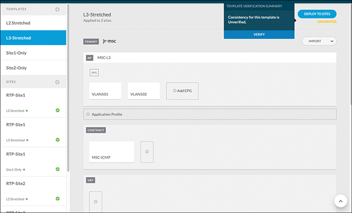
Figure 15-43 Running a Consistency Check on the Template L3-Stretched
After running this, you notice in the Site 1 deployment for this template that there is a warning notification. When you click on the deployment, there is a modification symbol under EPG VLAN502. If you click on the EPG, you see a warning indicating that modifications made to this EPG in the APIC were not done via the MSO, as shown in Figure 15-44.

Figure 15-44 Warning on EPG VLAN 502 That Modifications Were Made via the APIC
Solution
In order to ensure consistency, you want to again push the template configuration to both sites. You go to the template and click on the Deploy to Sites icon to again push the configuration to each site. You then notice that the ping that was previously failing is now working again.
Interested in what changed, you navigate to VLAN 502 in Site 1 via the APIC UI. Under the audit log for VLAN 502, you can see that at the time the configuration was redeployed via MSO, the contract MSC-ICMP was re-created, as shown in Figure 15-45. It appears that this contract was removed by another user at the time the issue started happening.

Figure 15-45 MSC-ICMP Contract Was Re-Created on VLAN 502 in Site 1
Using the consistency checker in MSO helps ensure that the policy is in sync if changes may have been made outside MSO.
Troubleshooting Programmability Issues: JSON Script Generates Error
You have been asked to provision a tenant by using some sort of programmability. In the near future, you are anticipating an ACI deployment in your data center that requires network provisioning with automation. You have started learning JSON and have created a sample script to validate in a lab before applying it in a production network. You end up with an issue despite calling out the proper JSON syntax through the POSTMAN REST client. An error is generated, as shown in Figure 15-46.

Figure 15-46 JSON Syntax Error
Solution
As noted in the error, that attributes tag is missing in the JSON payload, causing the script to fail. This is because the APIC controller that provides northbound REST APIs parses the JSON payload inside curly brackets with the object type, and it must include the attributes tag, as shown in Figure 15-47.
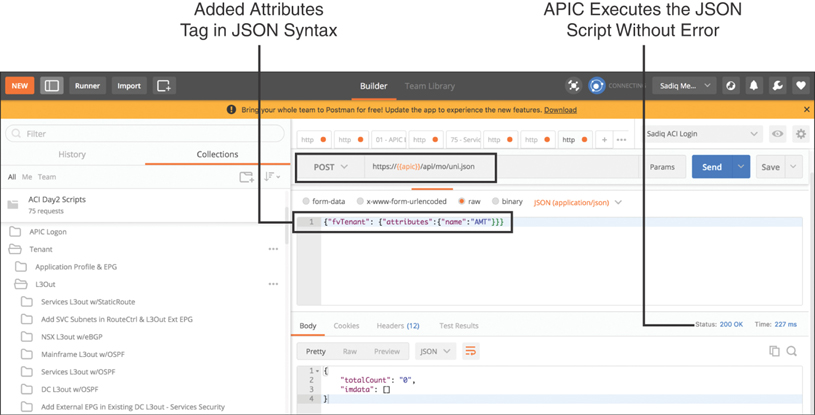
Figure 15-47 JSON Syntax, Including the attributes Tag
After you modify the JSON syntax to include the attributes tag, the APIC executes the script successfully (status code 200), and the new tenant AMT is created, as shown in Figure 15-48.
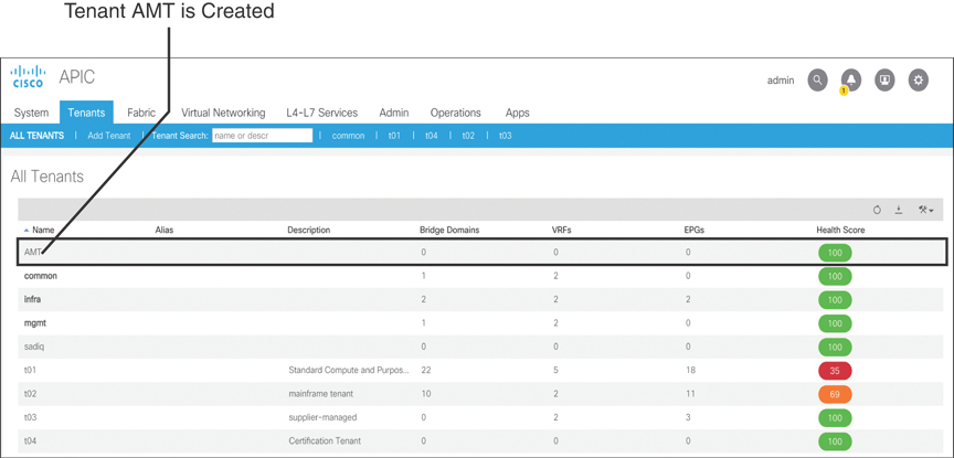
Figure 15-48 Tenant AMT Created
You can further verify this through the API Inspector tool in the APIC GUI. This tool is somewhat similar to a packet capture tool that displays each packet flowing through the wire. However, the API Inspector tool displays the API messages that the APIC GUI creates and sends internally to the operating system to execute a task.
To execute the API Inspector tool, you need to log on to the APIC GUI. In the top-right corner, right-click on the circular Help and Tools button and click the Show API Inspector tab to open the API Inspector window. Then you can create a new tenant through the APIC GUI. When this is done, you can switch to the API Inspector window, where you can clearly see in the payload the JSON syntax, including the attributes tag that ACI uses to execute the REST call (see Figure 15-49).

Figure 15-49 API Inspector Tool
Troubleshooting Multicast Issues: PIM Sparse Mode Any-Source Multicast (ASM)
Management calls you in because at the CEO’s annual employee town-hall meeting, which was supposed to be broadcast through real-time media service, but video streaming did not work. The initial report in the trouble ticket says that the Digital Media Engine (DME) was streaming media content through multicast group 239.80.0.89. This media server has recently been migrated from a legacy network and is now connected to an ACI leaf pair. For decades, your company’s network has been enabled to forward multicast traffic by running Protocol Independent Multicast (PIM) Sparse Mode. PIM Sparse Mode Any-Source Multicast (ASM), unlike its counterpart PIM Dense Mode, requires an RP that builds a shortest-path tree between the multicast sender and receiver. The RP (10.100.100.1) is running on your ASR 9000 WAN core router (ASR9K-WAN) outside the ACI fabric. After migrating the DME media server to ACI and connecting to leafs (Leaf-1001 and Leaf-1002), you configured PIM multicast in the fabric, pointing to the external RP (the ASR 9000 WAN core router) by using the Auto-RP feature. The ACI fabric is connected externally to the data center core router (DC-Core) through Border Leaf (BorderLeaf-202). Figure 15-50 shows the network topology enabled with multicast traffic.

Figure 15-50 Multicast-Enabled Network Topology
Solution
To troubleshoot multicast issues using PIM-ASM, you need to consider the following steps:
Step 1. Find out the multicast source, receiver and RP physical connectivity, and IP addresses.
Step 2. Ensure that the multicast source, receiver, and RP are IP reachable together through unicast.
Step 3. Ensure that PIM Sparse Mode is enabled on all the interfaces between multicast source (first-hop router [FHR]), receiver (last-hop router [LHR]), and RP.
Step 4. Verify that Internet Group Management Protocol (IGMP) Snooping is enabled on the interface connecting to the multicast receiver. (In most switch platform cases, it is already enabled by default.)
A regular multicast flow using PIM Sparse Mode ASM between source and receiver consists of the following:
The multicast source starts streaming and sends a PIM register message to the RP, using its unicast IP and multicast group addresses (S, G).
The multicast receiver interested in media streaming sends a PIM join message to the RP, using the multicast group (*, G).
RP establishes the shortest-path tree (SPT), and then the source and receiver start communicating directly.
You start troubleshooting the issue to determine the root cause. As a first step, you need to ask the application team to provide the IP address of the DME, which in this case is 50.88.197.34. You log in to your APIC via the CLI and run the show endpoints command, as shown in Example 15-33. You could also run the EP Tracker tool in the APIC GUI to find out which of the leafs in your fabric have learned the DME IP address.
Example 15-33 DME IP Address Is Learned on Leaf 1001
apic1# show endpoints ip 50.88.197.34
Legends:
(P):Primary VLAN
(S):Secondary VLAN


Dynamic Endpoints:
Tenant      : t01
Application : cp-infra-prod
AEPg        : services

 End Point MAC     IP Address    Node     Interface    Encap       Multicast Address
-----------------  ------------  -----    ----------   ---------   --------------
00:0C:29:B8:34:33  50.88.197.34   1001    eth1/16      vlan-1002   not-applicable

Total Dynamic Endpoints: 1
Total Static Endpoints: 0
The command output shows that the DME IP address 50.88.197.34 is learned on Leaf Node 1001 on interface eth1/16 with encapsulation VLAN 1002. After finding out the leaf through which DME is physically connected, you log on to it and try pinging the PIM RP address 10.100.100.1, sourcing from the DME IP subnet anycast gateway address 50.88.197.33, as shown in Example 15-34. The purpose of this is to ensure that the RP is unicast reachable from Leaf 1001, which is the First-Hop Router (FHR) where the DME is connected as multicast source. Example 15-34 shows the multicast RP address reachability from Leaf 1001 via the fabric where DME (multicast source) is connected.
Example 15-34 RP Address Reachability from Leaf 1001 Sourcing from the DME IP Subnet Gateway
Leaf-1001# show vlan extended

 VLAN Name                             Encap            Ports
 ---- -------------------------------- ---------------- ------------------------
 8    t01:dme-bd                       vxlan-16547722   Eth1/3, Eth1/15, Eth1/16
 9    t01:dme-epg                      vlan-1002        Eth1/3, Eth1/15, Eth1/16

Leaf-1001# show ip interface brief vrf t01:standard | grep vlan8
vlan8        50.88.197.33/27      protocol-up/link-up/admin-up

Leaf-1001# iping 10.100.100.1 -V t01:standard -S 50.88.197.33
PING 10.100.100.1 (10.100.100.1): 56 data bytes
64 bytes from 10.100.100.1: icmp_seq=0 ttl=252 time=1.055 ms
64 bytes from 10.100.100.1: icmp_seq=1 ttl=252 time=1.002 ms
64 bytes from 10.100.100.1: icmp_seq=2 ttl=252 time=1.001 ms
64 bytes from 10.100.100.1: icmp_seq=3 ttl=252 time=1.079 ms
64 bytes from 10.100.100.1: icmp_seq=4 ttl=252 time=0.954 ms

--- 10.100.100.1 ping statistics ---
5 packets transmitted, 5 packets received, 0.00% packet loss
round-trip min/avg/max = 0.954/1.018/1.079 ms
In the output shown in Example 15-34, you notice that encapsulation VLAN 1002 is bound to EPG dme-epg, which is associated to BD dme-bd forwarding on port Eth1/16. You quickly check the status of the anycast gateway of VLAN 8 with IP address 50.88.197.33 and are successful in pinging the RP address 10.100.100.1. Because you sourced the ping using the DME IP subnet anycast gateway address from Leaf 1001 and are successful at reaching the RP address, there is no need to perform this step from Border Leaf 202 or the data center core router.
Next, you check the IP reachability from the multicast receiver by pinging to the multicast source (50.88.197.3) and RP (10.100.100.1) addresses, as shown in Example 15-35. You get the IP address from one of the end users interested in receiving the multicast stream. In this case, it is 100.88.146.51.
Example 15-35 Multicast Receiver IP Reachability to the Multicast Source and RP
shussa36@eco:~> ip a
1: ens32: <BROADCAST,MULTICAST,UP,LOWER_UP> mtu 1500 qdisc pfifo_fast state UP group
  default qlen 1000
    link/ether 00:50:56:a1:d7:35 brd ff:ff:ff:ff:ff:ff
    inet 100.88.146.51/24 brd 100.88.146.255 scope global ens32
       valid_lft forever preferred_lft forever

shussa36@eco:~> ping 50.88.197.3
PING 50.88.197.34 (50.88.197.34) 56(84) bytes of data.
64 bytes from 50.88.197.34: icmp_seq=1 ttl=59 time=0.405 ms
64 bytes from 50.88.197.34: icmp_seq=2 ttl=59 time=0.423 ms
64 bytes from 50.88.197.34: icmp_seq=3 ttl=59 time=0.473 ms
64 bytes from 50.88.197.34: icmp_seq=4 ttl=59 time=0.374 ms

--- 50.88.197.34 ping statistics ---
4 packets transmitted, 4 received, 0% packet loss, time 3062ms
rtt min/avg/max/mdev = 0.374/0.418/0.473/0.043 ms

shussa36@eco:~> ping 10.100.100.1
PING 10.100.100.1 (10.100.100.1) 56(84) bytes of data.
64 bytes from 10.100.100.1: icmp_seq=1 ttl=252 time=0.598 ms
64 bytes from 10.100.100.1: icmp_seq=2 ttl=252 time=0.737 ms
64 bytes from 10.100.100.1: icmp_seq=3 ttl=252 time=0.582 ms
64 bytes from 10.100.100.1: icmp_seq=4 ttl=252 time=0.651 ms

--- 10.100.100.1 ping statistics ---
4 packets transmitted, 4 received, 0% packet loss, time 3062ms
rtt min/avg/max/mdev = 0.582/0.642/0.737/0.060 ms
Next, you log on to the router running RP and walk through, hop by hop, to verify PIM and RP reachability up to Leaf 1001, where the multicast source DME is connected. Example 15-36 shows the multicast RP and PIM status on the RP.
Example 15-36 Multicast RP and PIM Status on the RP
RP/0/RSP0/CPU0:ASR9K-WAN# show pim rp mapping
Sun Feb 16 21:52:33.470 UTC
PIM Group-to-RP Mappings
Group(s) 224.0.0.0/4
  RP 10.100.100.1 (?), v2
    Info source: 10.100.100.1 (?), elected via autorp
      Uptime: 6d06h, expires: 00:02:57
Group(s) 224.0.0.0/4
  RP 10.100.100.1 (?), v2
    Info source: 0.0.0.0 (?), elected via config
      Uptime: 6d06h, expires: never

RP/0/RSP0/CPU0:ASR9K-WAN# show pim interface
Sun Feb 16 21:54:21.352 UTC
PIM interfaces in VRF default
Address         Interface               PIM  Nbr   Hello  DR    DR
                                             Count Intvl  Prior

10.138.211.1    Loopback0               on   1     30     1   this system
10.100.100.1    Loopback9               on   1     30     1   this system
70.88.184.253   GigabitEthernet0/0/0/0  on   2     30     1   this system
Example 15-36 clearly shows that the ASR 9000 WAN core router is acting as the multicast RP with the Auto-RP feature. PIM is enabled on Loopback 0, Loopback 9 (used as the anycast RP address), and the GigabitEthernet0/0/0/0 interface connecting to the data center core router. You should also check to see if the multicast routing table on the RP is showing PIM join messages (*, G) and PIM register messages (S, G), as shown in Example 15-37.
Example 15-37 Multicast Routing Table on the RP
RP/0/RSP0/CPU0:ASR9K-WAN# show mrib route
Sun Feb 16 21:51:31.729 UTC

IP Multicast Routing Information Base
Entry flags: L - Domain-Local Source, E - External Source to the Domain,
    C - Directly-Connected Check, S - Signal, IA - Inherit Accept,
    IF - Inherit From, D - Drop, ME - MDT Encap, EID - Encap ID,
    MD - MDT Decap, MT - MDT Threshold Crossed, MH - MDT interface handle
    CD - Conditional Decap, MPLS - MPLS Decap, EX - Extranet
    MoFE - MoFRR Enabled, MoFS - MoFRR State, MoFP - MoFRR Primary
    MoFB - MoFRR Backup, RPFID - RPF ID Set, X - VXLAN
Interface flags: F - Forward, A - Accept, IC - Internal Copy,
    NS - Negate Signal, DP - Don't Preserve, SP - Signal Present,
    II - Internal Interest, ID - Internal Disinterest, LI - Local Interest,
    LD - Local Disinterest, DI - Decapsulation Interface
    EI - Encapsulation Interface, MI - MDT Interface, LVIF - MPLS Encap,
    EX - Extranet, A2 - Secondary Accept, MT - MDT Threshold Crossed,
    MA - Data MDT Assigned, LMI - mLDP MDT Interface, TMI - P2MP-TE MDT Interface
    IRMI - IR MDT Interface


(*,224.0.1.39) Flags: S P
  Up: 6d06h
  Outgoing Interface List
    Loopback0 Flags: II LI, Up: 6d06h
    GigabitEthernet0/0/0/0 Flags: LI, Up: 02:53:22

(10.100.100.1,224.0.1.39) RPF nbr: 10.100.100.1 Flags: RPF
  Up: 6d06h
  Incoming Interface List
    Loopback9 Flags: F A, Up: 6d06h
  Outgoing Interface List
    Loopback0 Flags: F IC, Up: 6d06h
    Loopback9 Flags: F A, Up: 6d06h
    GigabitEthernet0/0/0/0 Flags: F, Up: 6d06h

(*,224.0.1.40) Flags: S P
  Up: 6d06h
  Outgoing Interface List
    Loopback0 Flags: II LI, Up: 6d06h
    GigabitEthernet0/0/0/0 Flags: LI, Up: 01:20:00

(10.100.100.1,224.0.1.40) RPF nbr: 10.100.100.1 Flags: RPF
  Up: 6d06h
  Incoming Interface List
    Loopback9 Flags: F A, Up: 6d06h
  Outgoing Interface List
    Loopback0 Flags: F IC, Up: 6d06h
    Loopback9 Flags: F A, Up: 6d06h
    GigabitEthernet0/0/0/0 Flags: F, Up: 6d06h

(*,232.0.0.0/8) Flags: D P
  Up: 6d06h
This does not look good. You notice that the multicast routing table is only showing the (*, G) and (S, G) entries of Auto-RP multicast group 224.0.1.39 and 224.0.1.40; it shows nothing else. There is no PIM join message (*, G) from the multicast receiver, and there is no PIM register message (S, G) from the multicast source on multicast group 239.80.0.89.
You repeat these steps on the next-hop router from the RP, which in this case is the data center core router. Example 15-38 shows the multicast RP and PIM status, along with the multicast routing table on the data center core router.
Example 15-38 Multicast RP and PIM Status Along with the Multicast Routing Table on the Data Center Core Router
DC-Core# show ip pim rp
PIM RP Status Information for VRF "default"
BSR disabled
Auto-RP RPA: 10.100.100.1, uptime: 3w0d, expires: 00:02:30
BSR RP Candidate policy: None
BSR RP policy: None
Auto-RP Announce policy: None
Auto-RP Discovery policy: None

RP: 10.100.100.1, (0),
 uptime: 3w0d   priority: 255,
 RP-source: 10.100.100.1 (A),
 group ranges:
 224.0.0.0/4   , expires: 00:02:30 (A)

DC-Core# show ip pim interface brief
PIM Interface Status for VRF "default"
Interface            IP Address      PIM DR Address  Neighbor  Border
                                                     Count     Interface
Vlan100              100.88.146.1    100.88.146.1    1         no
Ethernet1/49         70.88.184.252   70.88.184.252   1         no
Ethernet3/4          80.88.192.30    80.88.192.30    1         no

DC-Core# show ip mroute
IP Multicast Routing Table for VRF "default"
You can tell that the data center core router is having no issues reaching the multicast RP. PIM is enabled on all the right interfaces. However, the multicast routing table is showing nothing for the group of interest. There is no PIM join message (*, G) from the multicast receiver. The multicast receiver is connected to a switch on VLAN 100 that is physically connected to the data center core router.
Now you repeat these steps on the next-hop router from the data center core router, which in this case is ACI Border Leaf 202. Example 15-39 shows the multicast RP and PIM status, along with the multicast routing table on ACI Border Leaf 202.
Example 15-39 Multicast RP and PIM Status Along with the Multicast Routing Table on ACI Border Leaf 202
BorderLeaf-202# show ip pim rp vrf t01:standard

PIM RP Status Information for VRF:"t01:standard"
BSR: Not Operational
Auto-RP RPA: 10.100.100.1/32
RP: 10.100.100.1, uptime: 21:25:04, expires: 00:02:57,
  priority: 0, RP-source: 10.100.100.1 (A), group-map: None, group ranges:
    224.0.0.0/4
BorderLeaf-202# show ip pim interface brief vrf t01:standard
PIM Interface Status for VRF t01:standard
Interface    IP address         DR address         Neighbor-count  Border-If
tunnel9      90.88.193.132      90.88.193.132/32   0               no
lo3          90.88.193.132/32   90.88.193.132/32   0               no
eth1/4       80.88.192.31/31    80.88.192.31/32    1               no

BorderLeaf-202# show ip mroute vrf t01:standard
IP Multicast Routing Table for VRF "t01:standard"

(*, 232.0.0.0/8), uptime: 3w0d, pim ip
  Incoming interface: Null, RPF nbr: 0.0.0.0
  Outgoing interface list: (count: 0)
From Example 15-39, it is observed that ACI Border Leaf 202 is having no issues reaching the multicast RP. PIM is enabled on all the right interfaces. However, the multicast routing table is showing nothing. One other thing you notice is that Border Leaf 202 has PIM enabled on interface tunnel9. You check the details of tunnel9 as shown in Example 15-40.
Example 15-40 Checking the Details of the tunnel9 Interface
BorderLeaf-202# show interface tunnel 9
Tunnel9 is up
    MTU 9000 bytes, BW 0 Kbit
    Transport protocol is in VRF "t01:standard"
    Tunnel protocol/transport is ivxlan
    Tunnel source 90.88.193.132
    Tunnel destination 225.1.192.0/32
    Last clearing of "show interface" counters never
    Tx
    0 packets output, 1 minute output rate 0 packets/sec
    Rx
    0 packets input, 1 minute input rate 0 packets/sec
From the output shown in Example 15-40, you can see that interface tunnel9 is established with source IP address 90.88.193.132 (the Loopback 3 interface) and destination IP address 225.1.192.0 (VRF instance GIPo address), as shown in Figure 15-51.

Figure 15-51 Multicast-Enabled VRF Instance Standard
In ACI, when you enable multicast on the VRF instance, the APIC assigns a unique GIPo address for the VRF instance. In this case, you enabled multicast on the VRF instance standard, and APIC assigned the 225.1.192.0 GIPo address.
Finally, as a last step, you check the RP and PIM status along with multicast routing details on Leaf 1001, which houses the multicast source—the DME streaming video content (see Example 15-41).
Example 15-41 Multicast RP and PIM Status Along with the Multicast Routing Table on Leaf 1001
Leaf-1001# show ip pim rp vrf t01:standard

PIM RP Status Information for VRF:"t01:standard"
BSR: Not Operational
Auto-RP RPA: 10.100.100.1/32
RP: 10.100.100.1, uptime: 1d5h, expires: 00:02:07,
  priority: 0, RP-source: 10.100.100.1 (A), group-map: None, group ranges:
    224.0.0.0/4
Leaf-1001# show ip pim interface brief vrf t01:standard
PIM Interface Status for VRF t01:standard
Interface    IP address        DR address        Neighbor-count     Border-If
tunnel39     127.0.0.100/32    127.0.0.100/32    1                  no

Leaf-1001# show ip mroute vrf t01:standard
IP Multicast Routing Table for VRF "t01:standard"

(*, 232.0.0.0/8), uptime: 3w0d, pim ip
  Incoming interface: Null, RPF nbr: 0.0.0.0
  Outgoing interface list: (count: 0)
From Example 15-41, you can see that Leaf 1001 is having no issues reaching the multicast RP. PIM is enabled on fabric interface tunnel39. However, the multicast routing table is showing nothing. You check the details of tunnel39, as shown in Example 15-42.
Example 15-42 Checking the Details of the tunnel39 Interface
Leaf-1001# show interface tunnel 39
Tunnel39 is up
    MTU 9000 bytes, BW 0 Kbit
    Transport protocol is in VRF "t01:standard"
    Tunnel protocol/transport is ivxlan
    Tunnel source 127.0.0.100/32
    Tunnel destination 225.1.192.0/32
    Last clearing of "show interface" counters never
    Tx
    0 packets output, 1 minute output rate 0 packets/sec
    Rx
    0 packets input, 1 minute input rate 0 packets/sec
Example 15-42 shows that tunnel39 is sourcing from localhost with destination IP address 225.1.192.0 (the VRF instance GIPo address). This means the only missing point in the entire multicast topology is that BD dme-bd is not enabled for PIM. To prove this, you need to run the command shown in Example 15-43 in the APIC CLI.
Example 15-43 Checking PIM Status on BD dme-bd
apic1# show bridge-domain dme-bd detail | grep PIM
PIM Enabled             : no
Based on this output, you know that on Leaf 1001 you will not see any PIM register (S, G) entry for multicast group 239.80.0.89, as verified in Example 15-44.
Example 15-44 Multicast Routing Table on Leaf 1001
Leaf-1001# show ip mroute vrf t01:standard
IP Multicast Routing Table for VRF "t01:standard"

(*, 232.0.0.0/8), uptime: 3w0d, pim ip
  Incoming interface: Null, RPF nbr: 0.0.0.0
  Outgoing interface list: (count: 0)
You enable multicast PIM on BD dme-bd, as shown in Figure 15-52.
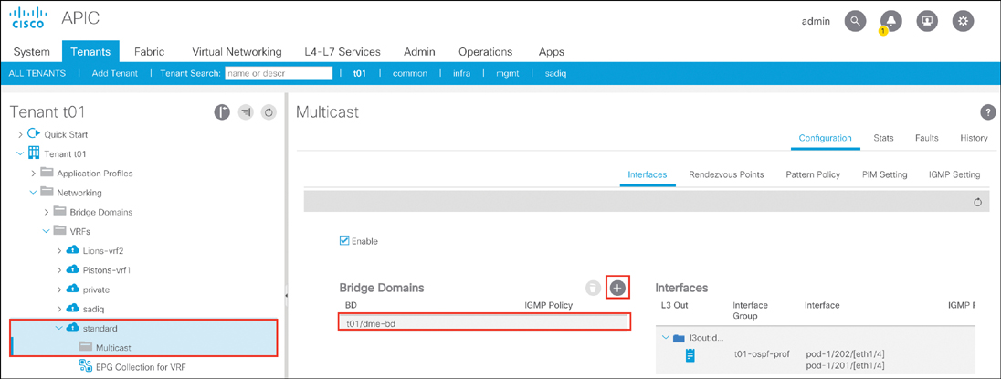
Figure 15-52 Enabling PIM on BD dme-bd
After you enable PIM on BD dme-bd, multicast streaming starts working. You check the status of IP multicast on all the routers involved, as illustrated in Example 15-45.
Example 15-45 Checking Multicast Status on All the Routers in the Network Topology
Leaf-1001:
Leaf-1001# show ip pim interface brief vrf t01:standard
PIM Interface Status for VRF t01:standard
Interface     IP address          DR address         Neighbor-count    Border-If
tunnel39      127.0.0.100/32      127.0.0.100/32     1                 no
vlan8         50.88.197.33/27     50.88.197.33/32    0                 no  ← BD SVI

Leaf-1001# show ip mroute vrf t01:standard
IP Multicast Routing Table for VRF "t01:standard"

(*, 224.2.133.134/32), uptime: 00:36:44, igmp ip pim
  Incoming interface: Tunnel39, RPF nbr: 10.2.44.64
  Outgoing interface list: (count: 1)
    Vlan8, uptime: 00:36:44, igmp

(50.88.197.34/32, 224.2.133.134/32), uptime: 00:36:45, ip pim mrib
  Incoming interface: Tunnel39, RPF nbr: 10.2.6.66 (pervasive)
  Outgoing interface list: (count: 1)
    Vlan8, uptime: 00:36:44, mrib

(*, 232.0.0.0/8), uptime: 2w4d, pim ip
  Incoming interface: Null, RPF nbr: 0.0.0.0
  Outgoing interface list: (count: 0)

(50.88.197.34/32, 239.80.0.89/32), uptime: 00:36:47, ip pim
  Incoming interface: Tunnel39, RPF nbr: 10.2.6.66 (pervasive)      ← Spine1 VTEP
  Outgoing interface list: (count: 0)

BorderLeaf-202:
BorderLeaf-202# show ip mroute vrf t01:standard
IP Multicast Routing Table for VRF "t01:standard"

(*, 224.2.133.134/32), uptime: 3d02h, ngmvpn ip pim
  Incoming interface: Ethernet1/4, RPF nbr: 80.88.192.30
  Outgoing interface list: (count: 1) (Fabric OIF)
    Tunnel9, uptime: 3d02h, ngmvpn

(50.88.197.34/32, 224.2.133.134/32), uptime: 3d02h, pim mrib ip
  Incoming interface: Tunnel9, RPF nbr: 10.2.6.66 (pervasive)
  Outgoing interface list: (count: 1)
    Tunnel9, uptime: 3d02h, mrib, (RPF)

(*, 232.0.0.0/8), uptime: 8w0d, pim ip
  Incoming interface: Null, RPF nbr: 0.0.0.0
  Outgoing interface list: (count: 0)

(50.88.197.34/32, 239.80.0.81/32), uptime: 00:00:54, pim ip ngmvpn
  Incoming interface: Tunnel9, RPF nbr: 10.2.6.66 (pervasive)      ← Spine1 VTEP
  Outgoing interface list: (count: 2) (Fabric OIF)
    Tunnel9, uptime: 00:00:54, ngmvpn, (RPF)
    Ethernet1/4, uptime: 00:00:54, pim          ← Connected to data center core

DC-Core:
DC-Core# show ip mroute

(*, 239.80.0.89/32), uptime: 00:23:28, igmp ip pim
  Incoming interface: Ethernet1/49, RPF nbr: 70.88.184.253  ← Connected to ASR 9000
  WAN
  Outgoing interface list: (count: 1)
    Vlan100, uptime: 00:23:28, igmp  ← Receiver connected and joins IGMP

(50.88.197.34/32, 239.80.0.89/32), uptime: 00:23:28, pim mrib ip
  Incoming interface: Ethernet3/4, RPF nbr: 80.88.192.31  ← Connected to Border Leaf
  202
  Outgoing interface list: (count: 2)
    Ethernet1/49, uptime: 00:23:28, pim  ← Connected to ASR 9000 WAN
    Vlan100, uptime: 00:23:28, mrib   ← Connected to receiver
DC-Core# show ip igmp groups 239.80.0.89

IGMP Connected Group Membership for VRF "default" - matching  Group "239.80.0.89"
Type: S - Static, D - Dynamic, L - Local, T - SSM Translated, H - Host Proxy
Group Address  Type  Interface   Uptime    Expires   Last Reporter
239.80.0.89    D     Vlan100     01:53:51  00:02:39  100.88.146.51  ← Receiver
  joined multicast group
ASR9K-WAN:
RP/0/RSP0/CPU0:ASR9K-WAN# show mrib route
(*,239.80.0.89) RPF nbr: 10.100.100.1 Flags: C RPF
  Up: 00:22:21
  Incoming Interface List
    Decapstunnel0 Flags: A, Up: 00:22:21
  Outgoing Interface List
    GigabitEthernet0/0/0/0 Flags: F NS, Up: 00:22:21   ← Connected to data center
  core

(50.88.197.34,239.80.0.89) RPF nbr: 10.100.100.1 Flags: L C RPF
  Up: 00:47:46
  Incoming Interface List
    Decapstunnel0 Flags: A, Up: 00:47:46
To summarize the solution in this case, you executed the following troubleshooting steps:
Step 1. Ensured that ACI learned the DME media server (multicast source) endpoint 50.88.197.34 on Leaf 1001 eth1/16 (refer to Example 15-33).
Step 2. Verified that the DME media server (multicast source) is associated to EPG dme-epg on encapsulation VLAN 1002 with BD dme-bd. Checked the connectivity by pinging the DME media server IP address 50.88.197.34 from the ToR ACI leaf (refer to Example 15-34).
Step 3. Checked IP reachability from multicast receiver to the DME media server (multicast source) and to the RP (ASR 9000 WAN core router) (refer to Example 15-35).
Step 4. Logged on to the ASR 9000 WAN core router and checked the RP and PIM interface status (refer to Example 15-36).
Step 5. Verified the multicast routing table on the RP (ASR 9000 WAN core router) (refer to Example 15-37).
Step 6. Logged on to the next-hop router from the RP toward the multicast source, which is the data center core router, and verified the RP, PIM interface status, and multicast routing table (refer to Example 15-38).
Step 7. Logged on to the next-hop router from the data center core router toward the multicast source, which is ACI Border Leaf 202, and verified the RP, PIM interface status, and multicast routing table (refer to Example 15-39).
Step 8. Verified that Border Leaf 202 is using the tunnel9 interface sourced from its Loopback 3 IP address 90.88.193.132 and destination by using the VRF instance GIPo address 225.1.192.0. The APIC assigned this GIPo address on the VRF instance when you enabled PIM multicast in ACI on the VRF instance (refer to Figure 15-50 and Example 15-40).
Step 9. Logged on to the next-hop router from ACI Border Leaf 202, which is ACI Leaf 1001, where the DME media server (multicast source) is connected, and verified the RP and multicast routing table (refer to Example 15-41).
Step 10. Checked the PIM interface status on ACI Leaf 1001, where the BD dme-bd anycast gateway (50.88.197.33/27) resides and found out that it is not enabled with PIM (refer to Example 15-43).
Step 11. Enabled the PIM interface on BD dme-bd, after which multicast started functioning normally (refer to Figure 15-51 and Example 15-45).
Summary
Throughout this book, you have explored the vast areas of ACI, and you should be on your way to becoming proficient in monitoring and troubleshooting an ACI fabric. This chapter demonstrates numerous troubleshooting scenarios that have been seen in the field and provides isolation steps you can follow to identify an issue, as well as remediation steps you can take to fix various issues.
Note
There are no Key Topics or Review Questions for this chapter.