
Chapter 2
Introduction to the ACI Policy Model
This chapter covers the following topics related to Cisco Application Centric Infrastructure (ACI):
The ACI policy model provides a convenient way of building application logic based on required policies. APIC automatically renders policies inside the fabric infrastructure. When an administrator or a process initiates a change in the configuration, the APIC actually executes it by changing the state of the objects in the ACI policy model. This policy model change then triggers a change to the actual physical infrastructure within the fabric. In ACI, everything is an object, whether it is a configuration, a fault, an event, or a fabric node. These objects are organized in a hierarchical policy model, and this approach is called a model-driven architecture.
ACI uses logical network provisioning of stateless hardware. It defines network-related application profiles, which are similar to service profiles in Cisco Unified Computing System (UCS).
Key Characteristics of the Policy Model
The following are the key characteristics of the ACI policy model:
As a model-driven framework, the APIC software maintains a complete representation of the administrative and operational state of the entire system. This means that when you make configuration changes, you are creating or modifying objects. Furthermore, if a configuration is incorrect and a fault is raised, that fault is represented as an object as well. Thus, everything in ACI is an object. ACI uses objects to represent and store the configuration, operational, and statistical data fabric-wide.
There are different types of objects, depending on where the configuration is deployed in the ACI fabric:
Logical: A logical object is a managed object such as AEPg (application EPG), BrCP (contract), or Filter (filter) that the user manipulates from the APIC through the GUI, the CLI, or API calls.
Resolved: Resolved managed objects are objects that the APIC automatically instantiates after resolving the logical model managed object.
Concrete: A concrete object is a managed object that delivers the actual configuration to each fabric node, based on the resolved model and attached endpoint.
Even if a configuration is defined for devices, that configuration is not deployed until a device is registered in the fabric.
No configuration can be done on an individual ACI physical infrastructure. All configuration is defined on the APIC in the form of policies and commanded through it for execution.
The APIC converts logical objects into concrete objects that the fabric hardware uses to configure the various network components. Each switch in the fabric validates these concrete objects and translates them into hardware-level programming.
How does the policy model work in ACI? Well, the interaction of the user with an ACI controller (APIC) happens through an application programming interface (API) to create or modify the objects in the policy model with an objective of creating and allocating resources in hardware. This is illustrated in the sequential flow process shown in Figure 2-1.
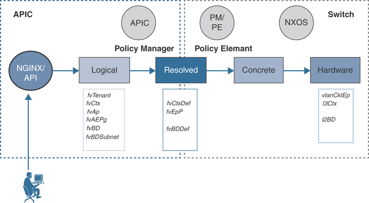
Figure 2-1 ACI Policy Model Flow
As Figure 2-1 shows, the user interacts with the APIC through an API to create or modify objects. This can be through a native REST API or through a Python SDK such as Cobra. The APIC runs a process called NGINX that creates logical managed objects such as fvTenant (tenant), fvCtx (VRF instance/context), fvAp (application profile), fvAEPg (application endpoint group), fvBD (bridge domain), and fvBDSubnet (subnet).
Note
The fv (fabric virtualization) represents a logical grouping of object classes.
Once the APIC creates or modifies the logical managed objects, it resolves the managed objects—such as fvCtxDef (context definition), fvEpP (endpoint profile), fvBDDef (bridge domain definition)—through the Policy Manager process and sends the instructions to switches to program them. The fabric switches running the object model operating system code understand the instructions from the APIC, and by using the Policy Element process, the APIC creates or modifies concrete objects—such as vlanCktEp (VLAN circuit endpoint), l3Ctx (Layer 3 context), l2BD (Layer 2 bridge domain)—and hence fabric switches finally program the instructions in their hardware.
These objects are organized in a hierarchical tree structure called the management information tree (MIT), as discussed in the following section.
Management Information Tree (MIT)
The fabric is composed of physical and logical components that are recorded in the Management Information Model (MIM) and can be represented in a hierarchical management information tree (MIT). You might have worked on X.500 network directory services (such as Microsoft Active Directory or Novell Directory Services) or SNMP MIB structure; the concept of MIT is similar. The MIM is stored and managed by processes that run on the fabric controller APIC. The APIC enables the control of resources by presenting their manageable attributes as object properties that can be inherited according to the location of the object within the hierarchical structure of the MIT.
Each node in the MIT represents a managed object (MO) or group of objects. MOs are abstractions of fabric resources. A MO can represent a concrete object, such as a switch, or a logical object, such as an application profile, an endpoint group, or a fault. Figure 2-2 provides an overview of the MIT.

Figure 2-2 Cisco ACI Policy Management Information Tree
The logical hierarchical structure of the object model starts with the policy universe (polUni) at the top and contains child objects. Additional objects contain parent objects and can contain child objects, as shown in Figure 2-3.
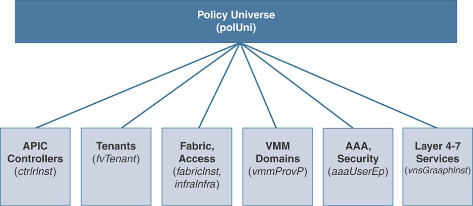
Figure 2-3 Cisco ACI Logical Policy Model
Each object in the tree is a MO that has a class, a globally unique relative name (RN), and a distinguished name (DN) that describe the object and its location in the tree. All the configurable entities and the structure of a managed object are represented as a class. For example, fvBD represents a class of bridge domain managed objects and all the configurable attributes in the system. All classes have a single parent and can contain multiple children, except the root of the tree, which is a special class called topRoot. Within the policy model, there are different packages that act as logical groupings of classes with similar entities for easier navigation in the MIT. Each class has a name, which is composed of the package name and a class name. For example, in the class called topRoot, top is the package, and Root is the class name. Similarly in the class called fvTenant, fv is the package, and Tenant is the class name.
MOs are identified by RNs. An RN is a prefix that is prepended by some sort of naming properties. For example, an object class fvTenant has the RN prefix tn- followed by the name of the MO, such as AMT; in this example, the managed object RN of class fvTenant would be tn-AMT. A relative name is unique in its namespace, which means that within the local scope of a MO, there can only ever be one RN using that name. To locate this unique managed object in the tree, the policy model uses a DN that tracks the entire path in the tree. In this example, the DN would be uni/tn-AMT. Note that topRoot is always implied and does not appear in the distinguished name.
The following managed objects contain the policies that govern the operation of the system:
The ACI policy model is stored in an object-oriented database that is synchronized throughout the cluster (comprising multiple APICs) to ensure that the configuration is sustained in the event of APIC failures. Different portions of the tree are stored in shards. Database sharding is a mechanism of splitting a large chunk of data into smaller units. One of the APICs in the cluster is a leader for a particular shard. If the leader goes down, another APIC takes over leadership. Configuration can be done from any APIC, but the leader for the shard is always what is updated. Once the leader is updated, the policy is synchronized to the remaining members in the cluster.
The tenant MO acts as a container or parent MO for policies that enable an administrator to exercise domain-based access control. Therefore, the tenant is the administrative boundary of the ACI system. The system provides the following four kinds of tenants:
User tenants are defined by the administrator according to the needs of the organization’s application-hosting requirements. They contain policies that govern the operation of resources such as applications, databases, web servers, network-attached storage, virtual machines, and so on. If you are a service provider, you might have one tenant per customer. Or, depending on how your organization is structured, you might need only a single tenant. A common deployment is to have a production tenant and a development tenant; another common deployment is to have a tenant named after each business entity.
The Common tenant is provided by the system but can be configured by the fabric administrator. It contains policies that govern the operation of resources that can be shared and consumed between all tenants, such as firewalls, load balancers, and intrusion detection appliances. The Common tenant cannot be deleted.
The Infra tenant is provided by the system but can be configured by the fabric administrator for certain needs. It contains policies that govern the operation of infrastructure resources such as the fabric Virtual Extensible Local Area Network (VXLAN) overlay. Examples of those policies exist in cases of multi-pod, multi-site, and remote leaf deployment (discussed in detail in Chapter 4, “ACI Fabric Design Options”). The Infra tenant cannot be deleted.
The Mgmt tenant is provided by the system but can be configured by the fabric administrator. It contains policies that govern the operation of fabric management functions used for in-band and out-of-band management configuration of fabric nodes. The out-of-band and in-band addresses, when configured, provide management access to the ACI fabric and also are used when connecting to external data collectors, orchestrators, and other managed devices.
Access policies define the configuration of switch specific parameters. Access policies include policies such as Control Plane Policing (COPP) or virtual port channel (VPC) domains and interface-specific parameters such as Cisco Discovery Protocol (CDP), Link Layer Discovery Protocol (LLDP), Link Aggregation Control Protocol (LACP), and interface speed. An administrator must configure these policies to enable tenant administrators with the capability to deploy endpoint groups (EPGs) on these ports.
Fabric policies govern the operation of the switch fabric ports, including such functions as Network Time Protocol (NTP) server synchronization, Intermediate System-to-Intermediate System (IS-IS) Protocol, Border Gateway Protocol (BGP) route reflectors, and Domain Name System (DNS). The fabric MO contains objects such as power supplies, fans, chassis, and so on.
Virtual machine manager (VMM) policies group virtual machine (VM) controllers in a domain with similar networking policy requirements. VM controllers can share VLAN or VXLAN space and application endpoint groups. The APIC communicates with the VM controller to publish network configurations such as port groups that are then applied to the virtual workloads. These network configurations map to EPGs in the ACI fabric to ensure consistent policy between virtual and physical workloads.
Authentication, authorization, and accounting (AAA) policies govern user privileges, roles, and security domains of the Cisco ACI fabric.
The Layer 4 to Layer 7 service integration automation framework enables the system to dynamically respond when a service comes online or goes offline. Policies provide service device package, inventory management functions, and traffic redirection to L4/L7 service devices using policy-based routing.
The hierarchical policy model fits well with the REST API interface. When invoked, the API reads from or writes to objects in the MIT. These objects are logically grouped into various classes. Your browser URLs map directly into distinguished names that identify the locations of the managed objects in the MIT. You can also query on a tree level to discover all members of an object. The data in the MIT can be described as a self-contained structured object encoded in XML or JSON natively.
Benefits of a Policy Model
The benefits of a policy-driven model are as follows:
Abstraction: Instead of deploying configurations directly into hardware, using a policy-driven model, you can abstract the control layer or policy from actual configuration. This allows you to replicate the policies for future use and provides ease in deployment on a large number of hardware infrastructure devices.
Flexibility: Defined policies can be modified as network capabilities and requirements change.
Reuse: Policies can be reused on future end hosts requiring the same settings.
Agility: It is possible to rapidly deploy a large number of application-hosting infrastructure devices.
Logical Constructs
The ACI policy model manages the entire fabric, including the infrastructure, authentication, security, services, applications, and diagnostics. Logical constructs in the policy model define how the fabric meets the needs of any of the functions of the ACI fabric. Figure 2-4 provides an overview of the ACI policy model logical constructs.
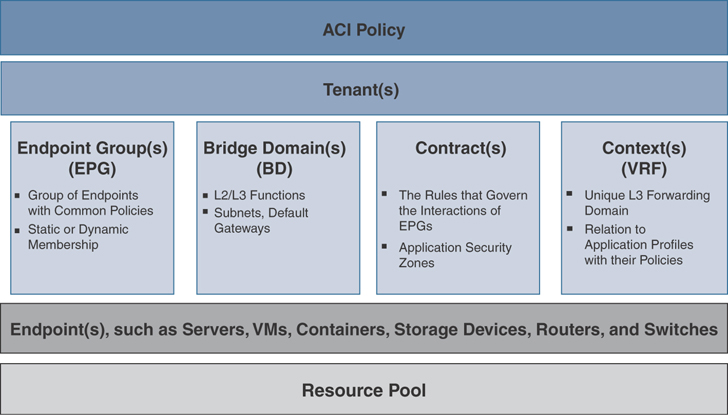
Figure 2-4 ACI Policy Model Logical Constructs
Administrators create predefined policies, either fabric-wide or tenant based, that contain application logic or shared resources that will be consumed by applications. These policies automate the provisioning of applications, network-attached services, security policies, and tenant subnets, which puts administrators in the position of approaching the resource pool in terms of applications rather than infrastructure building blocks. The application needs to drive the networking behavior—not the other way around.
The following sections provide details on the MOs in the ACI policy model.
Tenant Objects
A tenant object is represented in the MIT by the class fvTenant. It is a logical container that houses all application-related policies and allows for granular role-based access control (RBAC). Forwarding constructs created within a tenant are by default accessible only by the specific tenant they were created in, unless route leaking is used or forwarding constructs are created in the common tenant for shared resources. Within the tenant, you still need to create a VRF instance as your Layer 3 boundary, and you create bridge domains as the Layer 2 boundary that the EPG object consumes. A tenant can represent a customer in a service provider environment, an organization or a domain in an enterprise setting, or just a convenient grouping of policies. Figure 2-5 provides an overview of the tenant portion of the MIT.
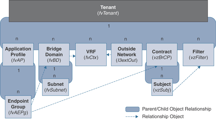
Figure 2-5 Tenant Object
Tenants can be isolated from one another for administrative reasons; however, interactions between tenants are possible through route leaking and contract exporting. You must configure a tenant object first before creating any child objects for it, such as VRF instances, bridge domains, application profiles, or endpoint groups. Starting with Release 2.3(1), the Cisco APIC introduced a quota policy, which allows the ACI administrator to define limits to what objects can be configured. This ensures that scalability can be enforced for each user-defined tenant. This feature is useful when you want to prevent any tenant or group of tenants from exceeding ACI maximums per leaf or per fabric or unfairly consuming the majority of available resources and potentially affecting other tenants on the same fabric.
Deletion of a user-defined tenant deletes all the subsequent application policies underneath. Cisco ACI provides three default tenants that users cannot delete: Common, Infra, and Mgmt.
VRF Objects
A virtual routing and forwarding (VRF) object, also known as a context, is a child object of a tenant object in the MIT. It is represented by the class fvCtx. A tenant object is the parent object, and you can create multiple VRF objects in it, based on your design requirements.
A VRF instance is a unique Layer 3 forwarding domain. Figure 2-6 shows the locations of VRF instances in the MIT and their relationships to other objects in the tenant object.
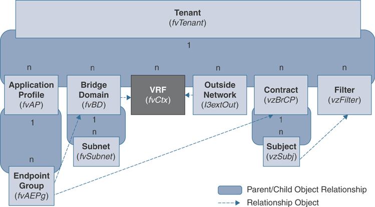
Figure 2-6 VRF Object
A VRF object defines a Layer 3 address domain. One or more bridge domains and external routed networks are associated with a VRF instance. All of the endpoints within the Layer 3 domain must have unique IP addresses because it is possible to forward packets directly between these devices if the policy allows it. Furthermore, all subnets defined under bridge domains that map to a VRF instance must be unique so that there is no overlapping IP space. One additional configuration of the VRF object in ACI allows the administrator to define whether the contract enforcement model should be used (whitelisting) or whether policy enforcement should be turned off for all hosts inside the VRF instance by configuring the Policy Control Enforcement Preference parameter.
Each VRF object is dynamically allocated a unique VXLAN VNID to be used when traffic is routed in the VRF. The VNID will be used to segment the Layer 3 traffic into unique L3 forwarding domains.
Application Profile Objects
An application profile object is a child object of a tenant object in the MIT and is represented by the class fvAp. It defines the policies, services, and relationships between EPGs. Figure 2-7 shows the locations of application profiles in the MIT and their relationships to other objects in the tenant object.
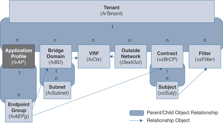
Figure 2-7 Application Profile Object
An application profile object is a logical container that houses one or more EPGs. Modern applications contain multiple components. For example, a three-tier e-commerce application could require a web server, an application server, a database server, data located in a storage area network, and access to outside resources that enable financial transactions. An application profile object contains as many (or as few) EPGs as necessary that are logically related to providing the capabilities of running an application. Keep in mind that an application profile object is just for organizational purposes; it is a logical container for grouping EPGs.
Endpoint Group Objects
An endpoint group object is a child object of an application profile object in the MIT. It is represented by the class fvAEPg. The EPG object is the most important object in the policy model because it is where you define the security policies that allow endpoints to communicate in the fabric. Figure 2-8 shows where application EPGs are located in the MIT and their relationships to other objects in the tenant object.

Figure 2-8 Endpoint Group Objects
An EPG is a managed object that contains a collection of endpoints. EPGs are designed to contain endpoints that have common policy requirements, such as security, VMM, QoS, or Layer 4/Layer 7 services. Rather than configure and manage endpoints individually, you place them in an EPG and manage them as a group. Why do we need EPGs? Say that your security team asks that all web traffic be switched to an intrusion detection system (IDS) for security and auditing purposes. To accomplish this, you would have to identify all web servers, configure a SPAN session on all switches to which the web servers connect, and plan for workload mobility. This would require hours of planning, and time on the weekend implementing change control—and it would be error prone.
EPGs simplify how new policy requirements are deployed in a data center network. You configure a policy on an EPG and then attach endpoints to that EPG by deploying VLANs on specific interfaces or extending VXLAN VNIDs to hypervisors. Within an EPG, the VLAN tag and the interface on which a host connects define the EPG to which the endpoint belongs. In the previous example, say that your security team wants to mirror all the web server traffic. You group all web servers to an EPG called Web-Servers. These web servers would attach to the fabric by using either an untagged VLAN or a tagged VLAN on the physical interfaces for which they attach. Now, the SPAN configuration needs to be defined in one place: the EPG. As devices move around, or as new web servers get added to the network, the APIC ensures that their SPAN configurations are pushed automatically to the leafs where these servers attach. This drastically decreases the time invested to deploy the requirements and brings a more positive feeling to the term change control.
There are a few ways that you can extend the EPG down to connected devices and begin classifying that traffic within the EPG:
Binding the EPG to an entire leaf switch (static leafs) by statically mapping a VLAN to the node
Binding an EPG to an individual port (static ports) by adding a VLAN to that port
Binding an EPG to a grouping of ports across multiple switches by adding a VLAN to the attachable access entity profile (AAEP)
Binding an EPG to a VMM domain, which pushes network policies to an external VMM controller, and ensuring that traffic in that virtual network is associated to the EPG
Note
If a leaf switch is configured for static leafs under an EPG, the following restrictions apply:
The static binding cannot be overridden with a static port since the static leaf deployment was deployed first.
Interfaces in that switch cannot be used for routed external network (L3Out) configurations using routed interfaces or subinterfaces, since the port mode is set to switchport.
The ACI fabric can contain the following types of EPGs:
Application endpoint group (fvAEPg)
Layer 2 external outside network instance endpoint group (l2extInstP)
Layer 3 external outside network instance endpoint group (l3extInstP)
Management endpoint groups for out-of-band (mgmtOoB) or in-band (mgmtInB) access
Layer 2 external EPGs were created to simplify the integration of legacy Layer 2 environments with the ACI fabric. All traffic entering from the legacy network is classified in the external EPG, and contracts are again used to define which endpoints inside ACI the legacy network can communicate with at Layer 2. The same can be achieved by using two different application endpoint groups by associating them to the same bridge domain. This is preferred by many users since they are more familiar with fvAEPg than with external bridged networks. If no contracts are required, and all traffic should be allowed by default between the devices in this Layer 2 boundary, simply extending the application EPG to the external switch would be the best path.
A Layer 3 external network EPG is used to classify endpoints or prefixes that exist outside the fabric and apply consistent policy as traffic enters or leaves the fabric. This allows you to classify traffic coming from an internal campus subnet differently than traffic coming from an internet-facing router and to use contracts to define what resources inside the data center external users have access to.
Virtual machine management connectivity to VMware vCenter is an example of a configuration that uses a dynamic EPG. Once the virtual machine management domain is configured in the fabric, policy can be pushed to the leaf switches as VMs dynamically connect in the ACI fabric. If VMs are powered on, migrated, or powered off, the policy can get added, moved, or deleted.
Further endpoint isolation can be accomplished by using microsegmentation. Microsegmentation associates endpoints from multiple EPGs into a microsegmented EPG according to virtual machine attributes such as IP address or MAC address. Virtual machine attributes include vNIC domain name, VM identifier, VM name, hypervisor identifier, VMM domain, data center, operating system, vSphere attribute tag, and custom attributes.
Advantages of microsegmentation include the following:
Stateless whitelist network access security with line rate enforcement
Per-microsegment granularity of security automation through dynamic Layer 4 through Layer 7 service insertion and chaining
Hypervisor-agnostic microsegmentation in a broad range of virtual switch environments
ACI policies that easily move problematic VMs into a quarantine security zone
For any EPG, the ACI fabric ingress leaf switch classifies packets into an EPG according to the policies associated with the ingress port. Microsegmented EPGs apply policies to individual virtual or physical endpoints that are derived based on the VM attribute, MAC address, or IP address specified in the microsegmented EPG policy.
Intra-EPG endpoint isolation policies provide full isolation for virtual or physical endpoints; no communication is allowed between endpoints in an EPG that is operating with isolation enforced. Isolation-enforced EPGs reduce the number of EPG encapsulations required when many clients access a common service but are not allowed to communicate with each other.
An EPG is isolated for all ACI network domains or none. While the ACI fabric implements isolation directly to connected endpoints, switches connected to the fabric are made aware of isolation rules according to a primary VLAN (PVLAN) tag.
Bridge Domain and Subnet Objects
A bridge domain represents a Layer 2 forwarding construct within the fabric. Figure 2-9 shows the locations of bridge domains (BDs) in the MIT and their relationships to other objects in the tenant object. It is represented by the class fvBD.
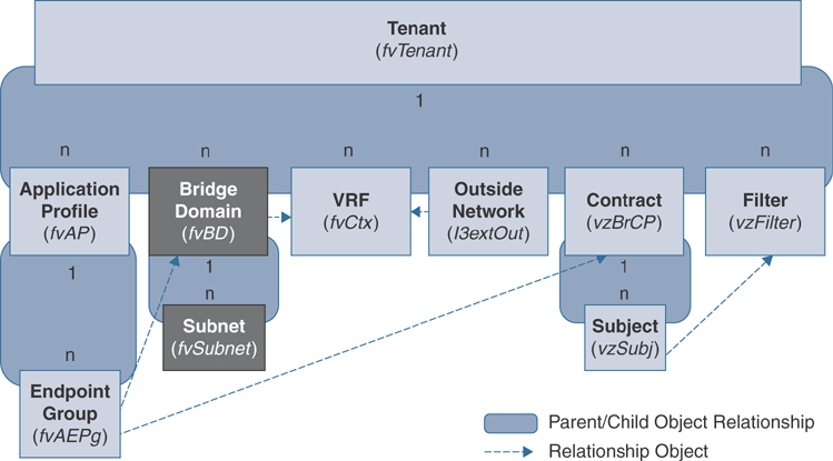
Figure 2-9 Bridge Domain and Subnet Objects
A BD must be linked to a VRF instance, even if the bridge domain is operating in a Layer 2–only mode. A BD can have one or more subnets associated with it. The BD defines the unique Layer 2 MAC address space and a Layer 2 flood domain if such flooding is enabled. Different options are available to define how Layer 2 traffic should be forwarded in the bridge domain. While a VRF instance defines a unique IP address space, that address space can consist of multiple subnets. Those subnets are defined in one or more BDs that reference the corresponding VRF instance.
The options for a subnet under a BD or under an EPG are as follows:
Public: The subnet can be advertised externally via a routed connection, using a dynamic routing protocol.
Private: The subnet applies only within its VRF instance.
Shared: The subnet can be shared with and exported to multiple VRF instances in the same tenant or across tenants as part of a shared service. An example of a shared service is a routed connection to an EPG present in another VRF instance in a different tenant. This is sometimes referred to as a shared L3Out. For more details on shared L3Out, please refer to the Cisco website.
Note
Shared subnets must be unique across the VRF instance involved in a communication. When a subnet under an EPG provides a Layer 3 external network shared service, the subnet must be globally unique within the entire ACI fabric.
Bridge Domain Options
A bridge domain can be configured to operate as a pure Layer 2 domain, or it can have unicast routing enabled. The Layer 3 routing capability is configured by enabling the Unicast Routing option on the bridge domain. The Layer 3 Configurations tab of the bridge domain panel allows an administrator to configure the following parameters:
Unicast Routing: If this setting is enabled and a subnet address is configured, the fabric provides the default gateway function and routes the traffic. Enabling unicast routing also instructs the mapping database to learn the endpoint IP-to-VTEP mapping for this bridge domain. The IP learning is not dependent on having a subnet configured under the bridge domain unless the setting Limit IP Learning to Subnet is configured.
Subnet Address: This option configures the SVI IP address(es), the default gateway for the bridge domain, which acts as an anycast address on all leafs where the bridge domain is deployed.
Table 2-1 outlines how the forwarding behavior for various scenarios is affected by the different settings on a bridge domain.
Table 2-1 Controlling BD Packet Behavior
BD Setting |
Description |
ARP Optimization |
When enabled, ARP packets are sent to the spine proxy, or to the leaf where the Target-IP endpoint resides. When disabled, ARP frames are flooded in the BD. |
L2 Unknown Unicast |
When set to Flood, unknown unicast frames are flooded in the BD. When set to Hardware Proxy, unknown unicast frames are sent to the spine proxy for a lookup. Note: Modifying the L2 Unknown Unicast setting causes the BD to get redeployed on the leaf switches. This means there is a slight disruption in service when making this change. |
Unknown L3 Multicast |
When set to Flood, if an L3 multicast packet is received, the packet is flooded to all interfaces in the BD, even if there are no receivers. When set to Optimized, if an L3 multicast packet is received, the packet is sent only to router ports. If there are no router ports, the packet is dropped. |
Multi-Destination Flooding |
When set to Flood in BD, floods the packet in the BD. When set to Flood in Encapsulation, floods the packet only in the VLAN encapsulation it was received in. When set to Drop, drops the packet. |
Bridge domains can span multiple switches because the EPG can exist anywhere in the fabric. If the bridge domain (fvBD) has the Limit IP Learning to Subnet property set to yes (which is the default setting in ACI Release 2.3 and later code), endpoint learning occurs in the bridge domain only if the IP address of the endpoint is within any of the configured subnets for the bridge domain or within an EPG subnet when the EPG is a shared service provider. Subnets can span multiple EPGs; one or more EPGs can be associated with one bridge domain. In hardware proxy mode, ARP traffic can be forwarded to an endpoint in a different bridge domain when that endpoint has been learned as part of the Layer 3 lookup operation.
Each BD gets dynamically allocated a unique VXLAN VNID to be used when traffic is switched or flooded in the BD. The VNID is used to segment the Layer 2 traffic into unique L2 forwarding domains.
Contract Objects
ACI involves the idea of the policy-driven network. ACI refers to security policies as contracts. Contracts are in some ways similar to access control lists (ACLs), but there are a few differences. First of all, ACLs can be applied only at Layer 2, such as in VLANs, or Layer 3, such as in IP address or subnets; in contrast, ACI contracts can be applied on an EPG where multiple endpoints are grouped together, regardless of their Layer 2 or Layer 3 attributes. Also, contracts can be easily applied bidirectionally, meaning you can apply the same policy from your WEB EPG, for example, to your APP EPG and vice versa. You can make it bidirectional by simply clicking a checkbox in contract configuration on an APIC instead of writing several more ACLs to make it work.
Let’s now look at some of the configuration components that go along with contracts:
Filter: The filter applies to the traffic you want to manage or, more specifically, the ports or protocols you want to permit or deny. Filter depends on intent or action. Usually, the action is to permit traffic. However, other actionable items are also allowed, including the following:
Deny (taboo): This could be for a specific use case, such as during a migration from legacy networks to ACI. In this case, you may specify to allow all traffic in a contract but set up taboos to deny certain traffic.
Redirect: This may be useful for sending traffic from an EPG to a Layer 4 through Layer 7 device such as a firewall, load balancer, or IPS/IDS.
Mark: You might want to mark traffic for quality of service reasons.
Label: A label is an identifier in a filter to specify a more complex relationship between endpoints.
Subject: A subject, also called a label, contains a filter with an action.
A contract contains one or more subjects that each contain one or more filters. Let’s consider an example of an Apache web server that requires HTTPS access for external clients, along with ICMP. The Apache web server talks to the app server on TCP port 2500 that then talks to the database server on UDP port 1100, as shown in Figure 2-10.
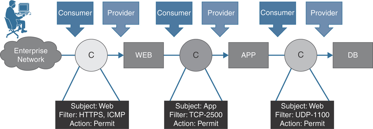
Figure 2-10 Contracts, Subjects, and Filters
In this example, an external user that is part of an external EPG consumes a contract that has a filter action to allow ports HTTPS and ICMP. The WEB EPG in this transaction is providing this contract. During the communication between WEB and APP EPGs, the WEB EPG consumes a contract that has a filter action of allowing TCP port 2500. The APP EPG is the provider for the contract. Similarly, the communication from the WEB EPG to the DB EPG is allowed via a contract with a filter permitting UDP port 1100. This contract is consumed by the APP EPG and is provided by the DB EPG.
In addition to EPGs, contracts (vzBrCP) are key objects in the policy model. EPGs can communicate with other EPGs only according to contract rules. Figure 2-11 shows the locations of contracts in the MIT and their relationships to other objects in the tenant object.

Figure 2-11 Contract Objects
Contracts govern the following types of EPG communications:
Between ACI fabric application EPGs (fvAEPg), both intra-tenant and inter-tenant
Between endpoints in the same EPG using intra-EPG contracts
Between ACI fabric application EPGs and Layer 2 external outside network instance EPGs (l2extInstP)
Between ACI fabric application EPGs and Layer 3 external outside network instance EPGs (l3extInstP)
Between ACI fabric out-of-band (mgmtOoB) or in-band (mgmtInB) management EPGs and external users
Labels, Filters, and Aliases
Subjects, filters, labels, and aliases are managed objects that are the components governing EPG communications. These managed objects enable mixing and matching among EPGs and contracts to satisfy various applications or service delivery requirements. Figure 2-12 shows the locations of application subjects and filters in the MIT and their relationships to other objects in the tenant object.
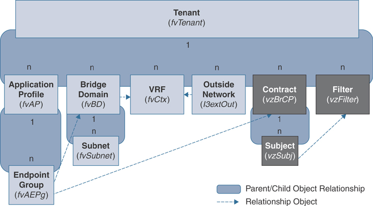
Figure 2-12 Subject and Filter Objects
Contracts can contain multiple communication rules for multiple EPGs. EPGs can both consume and provide multiple contracts. Labels control which rules apply when communicating between a specific pair of EPGs. A policy designer can compactly represent complex communication policies and reuse those policies across multiple instances of an application. For example, suppose you have multiple EPGs, five that would like to communicate ICMP with each other, and a separate five with the same requirements. However, one group should not be able to send ICMP to the other group. At first, you might think that you need to create two separate contracts, each with a subject and filter that allows ICMP. Instead, you can create a single contract and reuse that contract by defining labels. Labels allow you to selectively choose which EPGs will consume and provide a contract.
Contract Inheritance
To streamline the process of associating contracts to new EPGs, you can enable an EPG to inherit all provided and consumed contracts associated directly to another EPG in the same tenant. Contract inheritance can be configured for application, microsegmented, L2Out, and L3Out EPGs.
With Cisco ACI Release 3.0 and later, you can also configure contract inheritance for inter-EPG contracts as both provided and consumed. Inter-EPG contracts are supported on Cisco Nexus 9000 Series switches, including the EX and FX platforms.
You can enable an EPG to inherit all the contracts associated directly to another EPG by using the APIC GUI, NX-OS style CLI, and the REST API. In Figure 2-13, EPG A is configured to inherit Provided Contracts 1 and 2 and Consumed Contract 3 from EPG B (the contract master for EPG A).
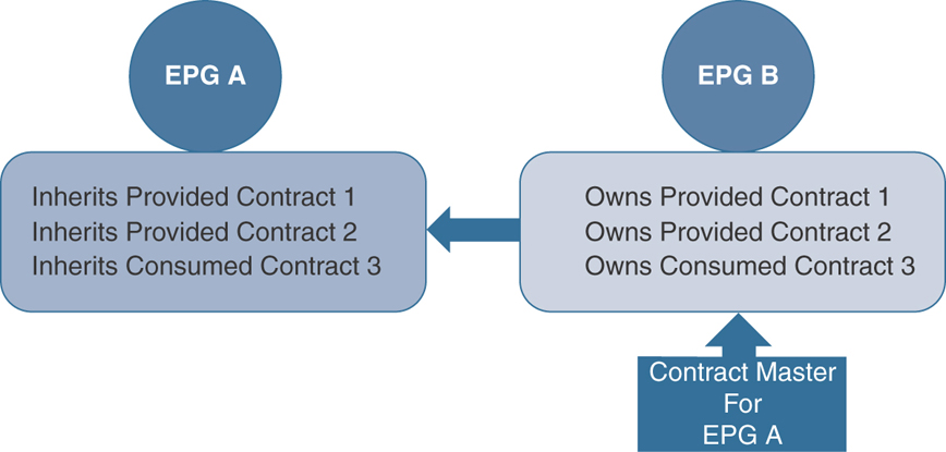
Figure 2-13 Contract Inheritance
Contract Preferred Groups
Contract preferred groups enable greater control of communication between EPGs in a VRF instance. If most of the EPGs in a VRF instance should have open communication but a few should have only limited communication with the other EPGs, you can configure a combination of a contract preferred group and contracts with filters to control inter-EPG communication precisely.
Two types of policy enforcements in a VRF instance are available for EPGs with a contract preferred group configured:
Included EPGs: EPGs can freely communicate with each other without contracts if they have membership in a contract preferred group. This is based on the source-any-destination-any-permit default rule.
Excluded EPGs: EPGs that are not members of preferred groups require contracts to communicate with each other. Otherwise, the default source-any-destination-any-deny rule applies.
EPGs that are excluded from the preferred group can communicate with other EPGs only if there is a contract in place to override the source-any-destination-any-deny default rule. Figure 2-14 illustrates this behavior.
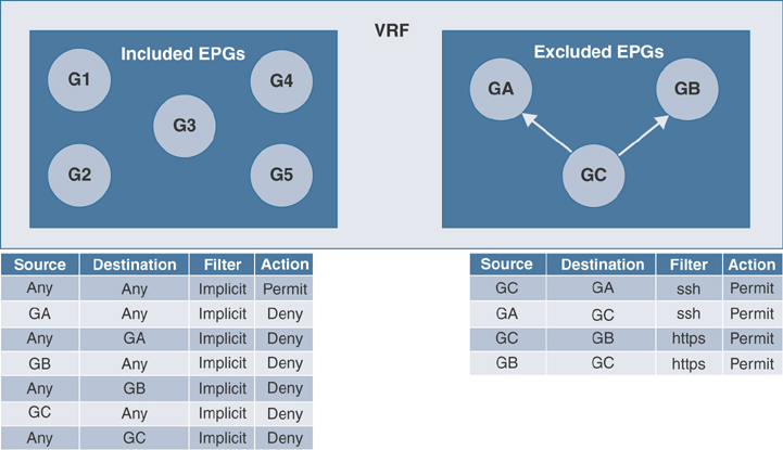
Figure 2-14 Contract Preferred Group
Contract preferred groups do have some limitations. In topologies where L3Out and application EPGs are configured in a contract preferred group and the EPG is deployed only on a VPC, you may find that only one leaf switch in the VPC has the prefix entry for the L3Out. In this situation, the other leaf switch in the VPC does not have the entry, and it therefore drops the traffic.
To resolve this issue, you can do one of the following:
Disable and reenable the contract group in the VRF
Delete and re-create the prefix entries for the L3Out EPG
vzAny
The vzAny managed object allows you to efficiently associate all EPGs in a VRF instance to one or more contracts (vzBrCP) instead of creating a separate contract object relationship for each EPG.
In the Cisco ACI fabric, EPGs can only communicate with other EPGs according to contract rules in Enforced mode. A relationship between an EPG and a contract specifies whether the EPG provides the communications defined by the contract rules, consumes them, or both. By dynamically applying contract rules to all EPGs in a VRF, vzAny automates the process of configuring EPG contract relationships. Whenever a new EPG is added to a VRF, vzAny contract rules automatically apply and control the traffic forwarding. The vzAny contract consumes less TCAM memory of fabric physical infrastructure and is the most efficient way of applying security policies in ACI. TCAM entries are generally specific to each EPG pair. In other words, even if the same contract is reused, new TCAM entries are installed for every EPG pair group that requires restrictive communication.
Outside Network Objects
Outside network policies control connectivity from ACI fabric to the external networks. This connectivity from ACI fabric to outside networks can occur at either Layer 2 or Layer 3. Outside network policies specify the relevant Layer 2 (l2extOut) or Layer 3 (l3extOut) properties that govern communications between an outside public or private network and the ACI fabric. A tenant can contain multiple outside network objects. Figure 2-15 shows the locations of outside networks in the management information tree (MIT) and their relationships to other objects in the tenant object.

Figure 2-15 Outside Network Objects
External devices, such as routers that connect to the WAN and data center core or existing Layer 2 switches, all connect to the front panel interfaces of a leaf switch. The leaf switch that provides such connectivity is known as a border leaf. As the name implies, the border leaf is the demarcation point of all traffic coming in and going out of the fabric from external networks. The border leaf switch interface that connects to an external device can be configured as either a bridged or routed interface. In the case of a routed interface, static or dynamic routing can be enabled. The border leaf switch can also perform all the functions of a normal leaf switch.
Physical Construct
ACI decouples the physical infrastructure from the logical construct to provide application agility. In the past, application deployment was often delayed because of unavailability of physical infrastructure to service applications. Provisioning a physical infrastructure separately and building application logic on top of it is a free and efficient way of hosting business applications. The physical construct in ACI governs the infrastructure-related configuration, as explained in the following sections.
Access Policies
Access policies in ACI control the configuration of port-level policies such as CDP, LLDP, and LACP as well as features such as storm control and how they are programmed on physical hardware. For fabric policies, three building blocks make up the access policy workflow:
Policies: A policy defines a specific characteristic without being applied to an interface or switch directly.
Policy groups: A policy group combines individual policies to create a consistent policy that can be reused.
Profiles: Profiles are used to tie policy groups to specific interfaces and switches.
Figure 2-16 illustrates a fabric access policy and its workflow.

Figure 2-16 Fabric Access Policy
Switch Policies
Switch policies are used to configure switch-specific parameters in ACI fabric. These policies govern switch-wide configurations that can be grouped together for common functionalities and applied to specific switch nodes. For ease and flexibility of configuration changes, these policies function through the following three main categories:
Policy: Switch policies are used to define switch-wide settings such as COPP policies or to define the VPC domain. The default policies work well in most environments and do not need to be customized in most instances.
Policy group: A policy group is used to tie different policies together and acts as an updating policy, so that if a change is made to a policy group, any switch profile using the policy group will be updated.
Profile: A switch profile is used to tie a fabric node (leaf or spine switch) to a specific switch policy group. A more critical function of a switch profile is the ability to tie a switch or range of switches to an interface profile. A recommended way to configure switch profiles is to create a one-to-one mapping of physical nodes to switch profiles and one switch profile that contains two switches per VPC domain. For example, if you had four switches in your fabric with node IDs 101 through 104, you would create four leaf profiles named Leaf101, Leaf102, Leaf103, and Leaf104. Each one of these profiles would contain only the corresponding node. If two VPC domains existed, one containing nodes 101 and 102 and the other containing 103 and 104, two additional switch profiles, named vPC101-102 and vPC103-104 and containing the corresponding nodes, could be created.
Figure 2-17 shows the relationships between switch policies and the interface policies.
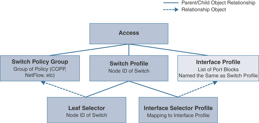
Figure 2-17 Object Relationship in Fabric Access Policy
Interface Policies
Interface policies are part of the Access Policies main tab in the APIC user interface. These policies are grouped together for common functionality of end-host connectivity and are assigned to the interfaces of your choice and requirement. For ease and flexibility of configuration changes, these policies function through the following three main categories:
Policy: Interface policies are used to configure interface-specific parameters, which range from enabling or disabling CDP or LLDP to specifying how LACP should react if PDUs are no longer received.
Policy group: The policy group is used to tie different policies together and acts as an updating policy, so that if a change is made to a policy group, any interface profile using this policy group will be updated. Policy groups can be created for a set of similar servers such as a hypervisor farm or a firewall cluster. It is recommended that you determine your balance of policy reuse versus flexibility. In many cases, a handful of policy groups can be created to meet the needs of most servers, but this severely restricts the ability to make a configuration change for one specific device. The interface policy group is also used to tie back into an AAEP (as discussed in the following section).
Profile: The interface profile is used to map Ethernet interfaces to an interface selector, which is mapped to a policy group. The interface profile is also mapped back to a switch profile. With an interface profile, you create a link between an interface policy group and a leaf switch on which you want to deploy the policy. To simplify the profiles and policies, you can create a single interface profile per switch in the fabric and a single profile per VPC domain. For example, if you had four switches in your fabric with node IDs 101 through 104, you would create four interface profiles named Leaf101, Leaf102, Leaf103, and Leaf104. Each one of these profiles will be mapped to the corresponding switch profile. If two VPC domains existed, one containing nodes 101 and 102 and the other containing 103 and 104, two additional switch profiles, named vPC101-102 and vPC103-104 and containing the corresponding nodes, could be created. If you follow this naming convention, you maintain a one-to-one mapping between switch profile and interface profile. This means that when you need to configure a new interface, all you need to do is create the appropriate port block under the interface profile. The interface profile is already mapped back to the switch profile, so these policies do not need to be created or modified every time.
Figure 2-18 demonstrates the relationships between interface policies and the AAEP.

Figure 2-18 Object Relationship Between Interface Policies and AAEP
Global Policies
Global policies configure VLAN pools, domains, and AAEP, as explained in the following sections.
VLAN Pools
A VLAN pool is used to define a range of VLANs that are allowed to be deployed on an ACI fabric. These VLANs will inevitably be trunked on an interface to map an endpoint to an EPG. Mapping a VLAN pool to an interface is similar to configuring the Switchport Trunk Allowed VLAN A-Z setting on a Nexus or Catalyst switch. These VLANs aren’t extended on the interface until the VLAN is created. With ACI, the pool creates a list of potential VLANs that can be extended on the physical interface.
The secondary role of a VLAN pool is to create a VNID range to assign to each VLAN. Features such as flooding in encapsulation or spanning tree require that BPDUs be flooded only within a specific VLAN and not the bridge domain or every EPG/VLAN associated with it. This is accomplished by using the encapsulation VNID instead of the BD VNID when sending traffic via the fabric.
A third use case of the VLAN pool is for VPC switches. When two switches are in a VPC domain, VPC and orphan port learned endpoints are synchronized between the two switches, and the VNID must be the same in order for the synchronization to be successful. Therefore, when a VLAN is mapped to an EPG that is deployed on a VPC pair, the domain from which that EPG is deployed must not have an overlapping VLAN pool.
Domains
ACI is built for a multitenancy environment where tenant administrators can have full access to deploying EPGs within the fabric. When deploying an EPG to a switch port, that VLAN is reserved for the specific EPG switch-wide. This could create a problem in which a single tenant uses up all VLANs available on a switch. To prevent this from happening, you can limit the VLANs a tenant can deploy on an interface. VLAN pools are not directly mapped to an interface; rather, VLAN pools are mapped to domains, and these domains are mapped to an AAEP. On the domain itself, the fabric administrator can restrict which tenant has access to which specific domain, which gives access to the VLAN pool. This means that in a single interface policy group, there is a relationship to a single AAEP. This AAEP can map to multiple domains, which can map to one or more VLAN pools. Because of this functionality, you can provide the server team a list of VLANs that they can use as well as a range of interfaces, and you can trust that they won’t use resources reserved for other tenants. There are five types of domains:
Physical (physDomP): Physical domains are used to deploy static path attachments to an EPG.
Virtual (vmmDomP): VMM domains are used when integrating virtual domains with the Cisco APIC.
External bridged (l2extDomP): External bridged domains are used when creating an external bridged network.
External routed (l3extDomP): External routed domains are used when creating an external routed network.
Fibre Channel (fcDomP): Fiber Channel domains are used when connecting Fibre Channel devices to the ACI fabric.
Attachable Access Entity Profile
In order to restrict what interfaces have access to what domains and, consequently, what VLAN ranges, an AAEP is needed. An AAEP is an object that acts as a filter for one or more domains on a particular interface. In order to create this mapping, an AAEP is associated to an interface policy group. The domain is then associated to the AAEP. Therefore, an interface on a switch has a given set of policies. Those policies are grouped on a policy group, and an AAEP is tied to the group, allowing access to certain domains. The interface is then allowed access to the VLAN pools that the domains provide. This allows an ACI admin to restrict access to certain VLANs so that they are not allowed to overlap. This is critical in a shared infrastructure where there are multiple tenants.
In most cases, a single AAEP for each domain type (physical, VMM, external L2, external L3) is sufficient. The physical and external domains map to a VLAN pool with static allocation ranges, and the VMM domain maps to a VLAN pool with dynamic allocation ranges. Figure 2-19 demonstrates the relationships of global policies and the interface and EPG.
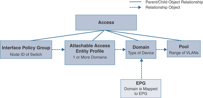
Figure 2-19 Object Relationship Between Global Policies and Interface Policy Group to an EPG
Managed Object Relationships and Policy Resolution
A managed object relationship outlines the relationship between managed object processes that do not share the parent/child relationship. MO relationships are established between the source MO and a target MO in one of the following two ways:
An explicit relationship (fvRsPathAtt) defines a relationship based on the target MO distinguished name (DN).
A named relationship defines a relationship based on the target MO name.
The dotted lines in Figure 2-20 show examples of common MO relationships.
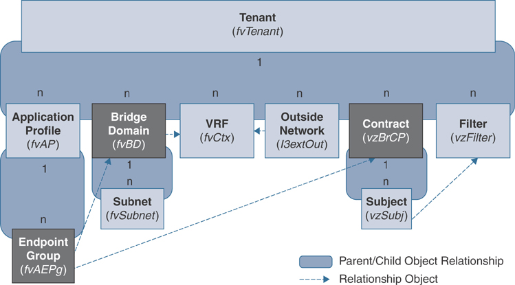
Figure 2-20 Managed Object Relationship
In Figure 2-20, the dotted line between the EPG and the bridge domain defines the relationship between those two managed objects. In this figure, the EPG fvAEPg contains the relationship MO fvRsBD that is named with the name of the target bridge domain MO (fvBD). For example, if production is the bridge domain name (fvBD=production), the relationship object name is tnFvBDName=production. There is a similar managed object relationship between the EPG fvAEPg and contract vzBrCP.
In the case of policy resolution based on named relationships, if a target MO with a matching name is not found in the current tenant, the ACI fabric tries to resolve in the common tenant. For example, if the user tenant EPG contains a relationship MO targeted to a bridge domain that does not exist in the tenant, the system tries to resolve the relationship in the common tenant. If a named relationship cannot be resolved in either the user-defined tenant or the common tenant, the ACI fabric attempts to resolve to a default policy. If a default policy exists in the current tenant, it is used. If it does not exist, the ACI fabric looks for a default policy in the common tenant. Bridge domain, VRF, and contract (security policy) named relationships do not resolve to a default.
Tags
A tag MO provides simplification in API operations. While executing an API operation, an object or a group of objects can be referenced by the tag name instead of by the DN. Tags are child objects of the item they tag; besides the name, they have no other properties.
You can use a tag to assign a descriptive name to a group of objects. The same tag name can be assigned to multiple objects. Multiple tag names can be assigned to an object. For example, to enable easy searchable access to all web server EPGs, assign a web server tag to all such EPGs. Web server EPGs throughout the fabric can be located by referencing the web server tag.
Default Policies
The initial values of the APIC default policies are taken from the concrete model that is loaded in the switch. A fabric administrator can modify default policies.
Warning
Default policies can be modified or deleted. Deleting a default policy can result in a policy resolution process completing abnormally. Be sure there are no current or future configurations that rely on a default policy before deleting a default policy. For example, deleting a default firmware update policy could result in a problematic future firmware update.
The ACI fabric includes default policies for many of its core functions. Examples of default policies include the following:
Bridge domain (in the common tenant)
Layer 2 and Layer 3 protocols
Fabric initialization, device discovery, and cabling detection
Storm control and flooding
VPC
Endpoint retention for caching and aging of learned endpoints in switch buffers
Loop detection
Monitoring and statistics
When the ACI fabric is upgraded, the existing policy default values persist, even if the default value changes in the newer release. When a node connects to an APIC for the first time, the node registers itself with the APIC, which pushes all the default policies to the node. Any subsequent change in the default policy is pushed to the node.
A default policy allows a fabric administrator to override the default values in the policy model by using explicit policy. In addition, if an administrator does not provide an explicit policy, the APIC applies the default policy. An administrator can create a default policy, which the APIC uses unless the administrator provides an explicit policy. For example, based on the actions the administrator does or does not take, the APIC will do the following:
Because the administrator does not specify the LLDP policy for the selected ports, the APIC applies the default LLDP interface policy for the ports specified in the port selector.
If the administrator removes a port from a port selector, the APIC applies the default policies to that port. In this example, if the administrator removes port 1/15 from the port selector, the port is no longer part of the port channel, and the APIC applies all the default policies to that port.
The following scenarios describe common policy resolution behavior:
A configuration explicitly refers to the default policy: If a default policy exists in the current tenant, it is used; otherwise, the default policy in the common tenant is used.
A configuration refers to a named policy (not the default policy) that does not exist in the current tenant or in tenant common: If the current tenant has a default policy, it is used; otherwise, the default policy in the common tenant is used.
Note
This does not apply to a bridge domain or a VRF instance in a tenant.
A configuration does not refer to any policy name: If a default policy exists in the current tenant, it is used; otherwise, the default policy in the common tenant is used.
Note
For bridge domains and VRF instances, this applies only if the connectivity instrumentation policy (fvConnInstrPol) in the common tenant has the appropriate bridge domain or VRF flag set. This prevents unintended EPGs from being deployed in common tenant subnets.
How a Policy Model Helps in Diagnosis
Now that you understand the policy model in ACI, let’s dive into a failure scenario and observe how you can leverage the ACI policy model concepts in diagnosing and resolving problems.
Say that you have received a complaint that your application servers hosted in ACI fabric are not reachable. The external network connectivity from ACI leafs is by route peering using OSPF, as shown in Figure 2-21.

Figure 2-21 Diagnosis Use Case
For this kind of issue, typically you need to check the following:
Are your border leafs up and running?
Is your OSPF neighbor relationship up?
Is any fault generated?
Checking this manually on each of the border leafs is time-consuming and extends your service downtime unnecessarily. In ACI, you can run a short query against your entire fabric to get all this information at once, as demonstrated in Example 2-1.
Example 2-1 Checking External Network Connectivity from ACI Leafs via Route Peering Using OSPF
https://{{apic}}/api/node/class/ospfAdjEp.json?query-target=self&rsp-subtree-
  include=faults
{
    "totalCount": "4",
    "imdata": [
        {
            "ospfAdjEp": {
                "attributes": {
                    "area": "0.0.0.13",
                    "dn": "topology/pod-1/node-201/sys/ospf/inst-default/
  dom-t01:standard/if-[eth1/1]/adj-50.88.193.130",
                    "operSt": "full",
                    "peerIp": "50.88.192.30",
              }
          }
      },
      {
          "ospfAdjEp": {
              "attributes": {
                  "area": "0.0.0.23",
                "dn": "topology/pod-1/node-202/sys/ospf/inst-default/
  dom-t02:mainframe/if-[eth1/1]/adj-60.88.152.130",
                    "operSt": "full",
                    "peerIp": "60.88.152.2",
                }
            }
        },
        {
            "ospfAdjEp": {
                "attributes": {
                   "area": "0.0.0.33",
                    "dn": "topology/pod-1/node-203/sys/ospf/inst-default/
  dom-t03:hadoop/if-[eth1/1]/adj-70.88.172.130",
                    "operSt": "full",
                    "peerIp": "70.88.172.2",
                }
            }
        },
        {
            "ospfAdjEp": {
                "attributes": {
                    "area": "0.0.0.43",
                    "dn": "topology/pod-1/node-204/sys/ospf/inst-default/
  dom-t01:standard/if-[vlan48]/adj-80.88.143.4",
                    "operSt": "full",
                    "peerIp": "80.88.143.104",
                },
                "children": [
                    {
                        "faultInst": {
                            "attributes": {
                                "ack": "no",
                                "cause": "protocol-ospf-adjacency-down",
                                "changeSet": "operSt (New: full)",
                               "code": "F1385",
                                "created": "2020-05-01T04:53:37.931-04:00",
                                "descr": "OSPF adjacency is not full, current state
  Exchange",
                                "domain": "external",
                                "highestSeverity": "warning",
                                "lastTransition": "2020-05-01T04:53:38.093-04:00",
                                "lc": "soaking-clearing",
                                "occur": "1",
                                "origSeverity": "warning",
                                "prevSeverity": "warning",
                                "rn": "fault-F1385",
                                "rule": "ospf-adj-ep-failed",
                                "severity": "warning",
                                "subject": "oper-state-failed",
                                "type": "operational"
                            }
                        }
                    }
                ]
            }
        }
     ]
   }
Note
The output in Example 2-1 is truncated to include only necessary values for explanation.
From Example 2-1, you can observe that the REST query provides quick feedback of the issue you are encountering. Out of four border leafs, one of the OSPF route peer relationships from Border Leaf ID 204 to external router is down and in OSPF EXSTART state. The REST query is calling an object class ospfAdjEp (an OSPF adjacency endpoint) fabric-wide, including the fault F1385 associated with the object class.
Summary
ACI is a policy-based object model in which configurations are stored as managed objects in a hierarchical fashion. All configuration management to fabric devices called nodes is carried out via a set of controllers in a replicated and synchronized cluster fashion. Traffic forwarding is still conducted directly by nodes called leafs and spines that constitute the ACI fabric. The Cisco ACI policy model is a top-down model based on promise theory that is meant to control a scalable architecture of defined network and service objects. This model provides robust repeatable controls, multitenancy, and minimal requirements for detailed knowledge by the Cisco APIC control system. The model is designed to scale beyond current requirements and to satisfy the needs of private clouds, public clouds, and software-defined data centers.
The policy enforcement model within the fabric is built from the ground up in an application-centric object model. This provides a logical model for laying out applications, which will then be applied to the fabric by the Cisco APIC. This helps to bridge the gaps in communication between application requirements and the network constructs that enforce them. The Cisco ACI model is designed for rapid provisioning of applications on the network that can be tied to robust policy enforcement while maintaining a workload-anywhere approach with single-pane-of-glass management.
In the next chapter, you will learn about ACI command-line interfaces.
Review Key Topics
If you are preparing to take the Implementing Cisco Application Centric Infrastructure - Advanced (300-630 DCACIA) exam to attain the Cisco Certified Specialist—ACI Advanced Implementation certification, be sure to review the key topics marked in this chapter as outlined in Table 2-2.
Table 2-2 Key Topics
Key Topic Element |
Description |
Page Number |
Paragraph |
Description of VLAN Pools |
Review Questions
The questions that follow are designed to help you prepare for the Implementing Cisco Application Centric Infrastructure - Advanced (300-630 DCACIA) exam if you are planning on acquiring the Cisco Certified Specialist: ACI Advanced Implementation certification.
1. What is the ACI policy model? How does it help in building application logic? (Choose two.)
The ACI policy model is a convenient model for building application logic through required policies.
Spine switches render the ACI policy model in the fabric with admin instructions.
In ACI, faults and events are not part of the policy model as they are generated as system logs.
The ACI policy model only deals with the configuration of stateful devices.
Policies are rendered automatically by APICs inside the fabric infrastructure.
2. How does the policy model work in ACI? How does it help in expediting the application deployment process? (Choose three.)
Configuration is applied through a centralized APIC system to fabric switches. This method ensures consistent changes and avoids human errors.
A user interacts with an APIC through the REST API to create and modify objects in the policy model, which ultimately results in the allocation of hardware resources.
An APIC only maintains the configuration of the fabric. For faults, an external server is required.
Switches must register to the fabric first before they can be configured by an APIC.
Everything in ACI is an object that is represented in a logical model only.
3. What are the benefits of using the ACI policy model? (Choose two.)
Policies that are programmed in hardware cannot be reused.
It slows down the deployment process as the fabric infrastructure scales.
Control policy is abstracted from the configuration in hardware.
It provides flexibility in modifying the defined policies as service requirements change.
4. What are contracts, and how are they used in ACI? (Choose four.)
Contracts are mapped to bridge domains for Layer 2 isolation.
Contracts are used to enforce security policies in ACI.
A contract allows or denies specific ports and protocols.
In ACI, contracts are applied on application EPGs to enforce security policies on endpoints, regardless of their Layer 2 or Layer 3 attributes.
Contract inheritance allows for modified filters on new EPGs.
A contract preferred group allows certain EPGs with full communication within a VRF instance while restricting others through a contract with restrictive filters.
A taboo contract allows all traffic but denies certain traffic. It is useful during migration cases.
5. What are switch policies? How does a switch policy work in ACI? (Choose four.)
Switch policies govern switchwide configurations, which can be grouped together for common functionalities and applied to specific switch nodes.
A VPC domain is defined under a switch policy group.
A COPP policy is defined under a switch policy.
A switch profile is used to tie a fabric node (leaf or spine switch) to a specific switch policy group.
The recommended configuration is to always create a one-to-one mapping between physical switches and the corresponding switch profile.
Switch policies are part of the Inventory tab in the Access Policies main menu bar.
6. What are interface policies? How do they work in ACI? (Choose three.)
Interface policies are part of Admin tab in main menu bar of the APIC GUI.
Interface policies govern the interface-related policies that are grouped together for common functionality of end-host connectivity.
CDP, LLDP, and LACP protocols are configured under an interface policy group.
To configure interface policies, first you need to configure policies, and then you include those policies in a policy group, and finally you create a profile with an interface selector and assign a policy group to it.
An attachable access entity profile is tied to an interface profile.
Interface policies are directly configured on a switch profile.
An interface profile associates the Ethernet interfaces through the interface selector and maps it to a switch profile.
7. What is an attachable access entity profile (AAEP)? What are the benefits of an AAEP? (Choose three.)
If multitenancy is not required, a single AAEP is sufficient for each domain type, such as physical, VMM, External L2, or External L3.
An AAEP restricts admins to access certain VLANs that are part of the domain on a particular interface to avoid overlap.
An AAEP is tied to an interface policy group and associated with a domain.
An AAEP is mapped to an application EPG to enforce interface policy.
An AAEP does not help in a shared infrastructure situation where there are multiple tenants.