
Although most X10 users start by controlling lamps and lighting, there’s no reason to stop there. Appliances from TVs and stereos to air conditioners are also “X10-able,” enabling you to start, and stop them with a click of your remote control or with signals from other X10 and X10-compatible devices. In this chapter, you’ll learn how to put X10 in charge of your appliances.
You can control almost any appliance with X10, providing you choose the right type of module:
For appliances up to 15 amps, use plug-in X10 or X10-compatible appliance modules. These are available in two-prong (polarized) or three-prong (polarized and grounded) forms, with or without pass-through connectors. Figure 5.1 shows typical examples. Plug-in appliance modules also support motors up to 1/3 horsepower, 400 watts for TVs, and up to 500 watts for incandescent lights.
For plug-in appliances with loads up to 20 amps, and for appliances that are semi-permanently installed (such as air conditioners, electric dryers, and electric stoves), use X10 outlet modules to replace normal electrical outlets. These are available in 15-amp and 20-amp ratings, 110-volt and 220-volt ratings, as well as split and duplex/one-address versions. See Figure 5.2 for typical examples. Note that outlet modules use the traditional X10 house and unit code dials.
For permanently wired-in appliances, motors, or fluorescent lights that use (or can use) wall-mounted on/off switches, use X10 switches rated for appliances, also referred to as relay switches. These switches are available in 110-volt or 220-volt ratings and 15-amp or 20-amp ratings.
Switches made by X10 use code wheels for programming, whereas some X10-compatible switches are programmed with a remote. Consult the instruction manual of the switch you are considering for installation and programming details (see Figure 5.3).
For permanently wired-in appliances, motors, or fluorescent lights that use built-in on/off switches, use an X10 or X10-compatible inline appliance switch. Some inline appliance switches support up to 30-amp loads, making them suitable for use with electric water heaters (see Figure 5.4). Appliance relays might use the traditional X10 house and unit code dials, or might be programmed with an X10 remote.
X10 appliance modules and switches differ from lamp modules and switches in several important ways:
Lighting support
Electrical loads
Programmability
The following sections discuss these differences in more detail.
X10 appliance control devices, unlike lamp control devices, don’t support dimming, even when used with incandescent or other dimmable lights. Therefore, if you want to dim your lights, make sure that you’re not using an appliance control device to control your lamps or light fixtures.
Also, X10 appliance modules do not respond to the All Lights On command available with many tabletop controllers and computer interfaces. They do respond to the All Units Off command, however. See Chapter 6 for more information about controllers that support these commands.
Although appliance control devices don’t support dimming or All Lights On, they do have three advantages over lamp modules when used in lighting applications:
Appliance control devices can be used with fluorescent lights, which are often used in kitchens, garages, and workshops.
Appliance control devices can be used to control combination fan/light fixtures.
Appliance control devices can be used with higher wattage incandescent lights than lamp control devices.
X10 appliance control devices are rated to handle resistive (ampere) and motor (horsepower) loads, whereas lamp modules are not. If you use an appliance, motor, or fluorescent light with an X10 lamp control device, you could damage whatever is plugged into the control device. Make sure that you use lamp modules only for incandescent lamps; use appliance modules for other applications.
X10 appliance modules are labeled to indicate the electrical loads they are designed to handle. Figure 5.5 provides a typical example.
Most X10 appliance control modules, regardless of their form, are relatively simple devices. Usually, they are programmed using the traditional house code and unit code wheels, and are designed for one-way (receive-only) operation.
However, if you want to use an X10 appliance module with remote access, particularly via the Internet (see Chapter 12, “Accessing X10 Home Control via Your Home Network and the Internet,” for details), consider using a plug-in module that supports two-way operation. Two-way operation enables a module to send status messages back to the controller.
If you want to use an appliance module to control devices that will be part of a scene, such as “dim lights, turn on air conditioner, turn off fan,” you can use computer control (see Chapter 11, “Accessing X10 Home Control via Your Home Computer,” for details). However, if you want to store scene commands within the module itself so that you can trigger them from a remote control or tabletop controller, use appliance modules with scene storage capability. See Chapter 6 for details about creating scenes.
The process of installing X10 appliance control modules ranges from simple to complex. If you can use two or more module types to perform a task, be sure to consider electrical safety factors in your decision.
The following sections cover the process for each type of installation in detail.
To install a plug-in X10 appliance module, such as the ones shown in Figure 5.1, follow this basic process:
Find a suitable AC electrical outlet near the appliance you want to control.
Make sure that the power switch on the lamp or appliance is set to On.
Unplug the lamp or appliance from its outlet.
Plug the lamp or appliance into the module.
Plug the module into the AC outlet.
Set the house and unit code dials to the desired settings.
If necessary, set the remote control or tabletop controller to control the house and unit code settings used for this module. If you use a wireless remote, the module, the transceiver, and the remote must all use the same house code.
Turn the module on and off remotely.
If your X10 appliance module uses house and unit code dials, use a small screwdriver to set the dials. With this type of module, you can set it before you plug it into the outlet, as shown in Figure 5.6.
Black & Decker’s freewire system (refer to Chapter 4, “Using X10 to Control Home Lighting,” for more information) includes an X10-compatible appliance receiver module (see Figure 5.7). This unit has the same ratings as other appliance modules. However, the house and unit code dials on the freewire module are concealed beneath a hinged cover.
The unit code wheel is divided into colors. Each color can be used to represent a zone or room. For easiest operation when using a freewire remote, you should use the zone system when installing modules. For example, you could use the yellow zone for modules in the living room. With the freewire remote control, you can turn off each module in a group with the cover closed, or by opening the cover and using the round on/off buttons to turn off the selected group.
If your X10-compatible appliance module doesn’t have house and unit code dials, consult the module’s instructions for setting the house and unit codes. To program a Smarthome appliance module or relay switch, for example, press the Set button on the module or switch, and then use a remote, tabletop controller, or computer interface to send the house and unit code you want to use with the module or switch. Figure 5.8 illustrates this process.
Caution

In the example shown in Figure 5.8, the module uses the first X10 code you send. Make sure that code is recorded on your worksheet (as discussed in Chapter 4) because you can’t look at the unit to determine its settings.
If you forget the code you sent to the unit, unplug it, press its reset button, and start over.
The process of installing X10-compatible wall switches for use with appliances is similar to the process used for installing an X10 light switch (refer to Chapter 4). However, relay wall switches made for appliances always use the neutral wire, unlike the simple on/off switch installed in Chapter 4.
To install an X10-compatible wall switch that uses a neutral wire, follow this procedure:
Turn off the wall switch.
Disconnect power to the switch by turning off the appropriate circuit breaker or removing the appropriate fuse (see Figure 5.9).
Remove the switch wall plate.
Remove the screws holding in the switch.
Pull the switch out from the wall box so that the screws holding the wires in place are visible.
Make sure that the switch is still turned off.
Caution
Many wall boxes used for switch installations don’t have a neutral wire (white) run to the box. If you want to install a switch for lights (refer to Chapter 4) or other uses (this chapter) that require a neutral wire, don’t do it if the neutral wire is not available. X10-compatible switches made for appliance control always require the neutral wire; installing such a switch without using the neutral wire can create a fire hazard.
If your existing switch doesn’t use the neutral wire but you are installing a switch that does, look toward the back of the wall box for two or more white wires connected to each other with a wire nut. For dimmer applications, you can purchase switches that don’t require the neutral wire from Smarthome (SwitchLinc RX series).
Don’t confuse the neutral wire with the bare copper ground wire. This is not used in most X10-compatible switch installations, whether for lighting (refer to Chapter 4) or appliance control (this chapter).
Before continuing, you must test the lines to determine which wire is the line wire (carries current at all times—hot) and which line is the load wire (carries current when the switch is turned on—switched-hot) using a voltage sensor.
Return to the circuit breaker and turn on the power to the switch.
Use a voltage sensor to determine which wire is hot (line wire) and which is switched-hot (load wire) (see Figure 5.10).
The line wire will cause the voltage sensor to light up. Note which wire is the line (hot) wire and which is the load (switched-hot) wire. You need to connect these wires to the correct leads on the new switch.
Shut off the power to the switch at the electrical panel.
Remove the screws connecting the power wires to the switch (see Figure 5.11).
To connect the new switch, follow these directions:
Connect the line wire from the wall box to the switch connector used for the hot (line) wire. Most switches use a screw connection as in Figure 5.12, but a few use a black wire marked Line.
Remove the wire nut from the neutral (white) wires at the back of the wall box.
Connect the neutral wire from the wall box to the switch connector used for the neutral wire. Most switches use a screw connector as in Figure 5.12, but a few use a white wire marked Neutral.
Connect the load wire from the wall box to the switch connector used for the switched-hot (load) wire. Most switches use a screw connection as in Figure 5.12, but a few use a red wire marked Load.
Figure 5.12 shows what a typical appliance switch using the neutral line looks like after it has been connected to the wall box wiring.
After connecting the switch to the appropriate wires, complete the process:
Push the line, load, neutral, and ground wires back into the switchbox (the ground wire is not used).
Reattach the switch to the switchbox.
Reconnect power to the switch.
Follow the instructions provided with the switch for setting house and unit codes. In most cases, these codes are set by adjusting code wheels, which might require removing the switch toggle plate.
Turn on and turn off the device using the switch.
Use your X10 remote control or tabletop controller to turn the device off and on.
Reattach the wall plate.
Even if you have installed X10 or X10-compatible light switches, installing an X10 electrical outlet can be a challenge for several reasons:
The wires used for electrical outlets are thicker and harder to bend than those used for switches.
You use line, neutral, and ground wires to install an electrical outlet instead of line, load, and neutral wires.
You might encounter a miswired outlet, so you should use a voltage sensor to determine line and load wires.
Although a miswired X10 outlet module will work, it presents a fire and safety hazard.
The outlet module uses most of the space in the electrical box, leaving relatively little room for the wires after the existing outlet has been replaced with the X10 electrical outlet.
When you push the outlet module back into place, you must make sure that you don’t nick the insulation around the wires or trap bare wires between the back of the module and the back of the wall box.
I suggest that you use a plug-in appliance module instead of an outlet module. However, if you decide that you must install an outlet module, be especially careful.
Figure 5.13 shows a typical split (one outlet X10 controlled, the other uncontrolled) outlet module. Note the clear identification of each wire on the rear of the module.
To install an X10 electrical outlet, follow this procedure:
Set the house and unit code dials to appropriate values (use the worksheet in Chapter 2 for a reference). Refer to Figure 5.6 earlier in this chapter.
Shut off the power to the outlet at the electrical (circuit breaker or fuse) box.
Use a voltage sensor to verify the power is out (see Figure 5.14).
Remove the faceplate over the existing outlet.
Remove the screws holding the outlet to the wall box.
Pull the outlet out of the wall box.
Depending on the outlet and the original installer’s preferences, the wires might be held in place by screws on the sides of the unit or by locks inside the outlet. The outlet shown in Figure 5.15 uses a screw to secure the bare copper ground wire, but internal locks to hold the line and neutral wires. To release the locks, insert a small straight-bladed screwdriver into the slot next to the wire hole and wriggle the screwdriver until the wire releases.
Connect the line (black), neutral (white), and ground (green) wires from the new X10 outlet to the corresponding wires in the wall box using wire nuts (usually provided with the new outlet). Note that the ground wire is often a bare copper wire. Figure 5.16 shows the outlet after being secured to the wires from the wall box.
Push the wires back into the box. You might need to bend the wires to provide sufficient clearance for the outlet because X10 outlets tend to be deeper front-to-back than conventional outlets.
Attach the X10 outlet to the box using the screws provided with the outlet.
Attach the new outlet cover to the outlet.
Turn on the power at the electrical box.
If the outlet is a split type (one outlet uncontrolled), plug a device into the uncontrolled outlet and turn it on. It should run normally.
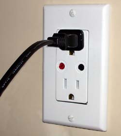
Plug a device into the controlled outlet (or either outlet, if both are X10 compatible) and use the X10 remote to turn on and turn off the device. Figure 5.17 shows you what your outlet should resemble after you complete installation and plug in an appliance.
Repeat step 13 with the other outlet if both outlets are X10 controlled.
If both outlets work, you’re all set!

To install an X10-compatible appliance inline relay module, such as the one shown in Figure 5.18, see the instructions packaged with the module. You will need to connect this module to the wiring running to the device you want to control.
Connecting your appliance to an X10 appliance module is simple:
Turn off the appliance.
Plug the appliance into an X10-controlled outlet.
Turn on the appliance.
Select the appropriate button on the X10 remote control or tabletop controller to activate that appliance.
If you want your appliance to turn on at the same time as another X10 device, set both for the same house and unit codes. However, keep in mind that this simplistic approach will prevent you from using the devices independent of one another unless you get out of your easy chair and turn them on or off yourself.
An X10 timer enables you to run an appliance, such as a coffeemaker or fan, when you want it to run. To automate remote operation of your appliance, use a programmable X10 control module. An X10-to-computer interface enables you to control an appliance remotely via your home network or the Internet.
See Chapter 6 for more information about X10 timers, and Chapters 10–12 for more information about controlling your X10 system remotely via telephone, computer, and the Internet.
X10 appliance control is fairly straightforward. But, if you’re having problems, use the suggestions in this section to get your installation squared away.
If your X10 module or switch isn’t set to the same house code as your remote, it will not be able to pick up X10 signals. If your X10 module is set to a unit code different from the unit code you selected, it won’t work.
Make sure that you’re pressing the correct key for your light’s unit code. With modules that use house and unit code dials, you’ll need to physically inspect the module or light switch to see its settings. If your X10 module can be programmed with a remote, try reprogramming it to the desired house and unit codes.
If a device plugged into or controlled by an X10 or X10-compatible module is turned off using its own on/off switch, X10 cannot control that device until it is turned on again.
Turn the device’s own power switch to the On position and retry turning it off and on with your X10 remote.
If one remote can’t control the device, try another. The remote’s batteries might be run down. Or, if the remote uses a programmable chip, it might need to be reprogrammed. See the remote’s instructions for details.
If none of your X10 devices can be controlled with a remote, your transceiver module might be unplugged, be set to the wrong house code, or have failed.
If none of your X10 devices can be controlled with a tabletop controller, it might be set for the wrong house code, might not be plugged in, or might be plugged into a surge suppressor.
It’s just as important to turn the power back on after you install a new wired-in-place X10 module, outlet, or switch as it is to turn off the power before you start.
Use a voltage tester to see whether other outlets on the same circuit are working. If none of the outlets are working, you need to turn the power back on at the electrical box.
If other outlets on the same circuit as your newly installed outlet are working, but your outlet has no power, you have a wiring problem. Shut off the power immediately and recheck your installation! The wire nuts connecting the outlet to the wall box might have come loose when you pushed the wires back into the box, or you might have miswired the outlet or switch. If your outlet still won’t work after you redo the wiring and restart it, it might be damaged.
If some of your X10 or X10-compatible devices work some of the time, but not consistently, and you have ruled out the problems discussed in this chapter, you might have signal quality problems. For advanced troubleshooting techniques and tools, see Appendix B, “Troubleshooting X10.”