I'm fixing a hole where the rain gets in And stops my mind from wandering Where it will go. | ||
| --John Lennon and Paul McCartney | ||
A particle physicist works with atoms, a baker and a banker both work with dough, and a compositor works with selections—lots and lots of selections.
If compositing were simply a question of taking pristine, perfect foreground source A and overlaying it onto perfectly matching background plate B, there wouldn't even be a compositor in the effects process; an editor could accomplish the job before lunchtime.
Compositors break images apart and reassemble them, all in motion. Often, it is one element, one frame, or one area of a shot that needs special attention. By the clever use of selections, a compositor can save fellow artists and camera operators, taking control of whatever part of the source footage is necessary.
In this chapter, we'll look at the foundation techniques that define how a layer merges with those behind it. Then Section II, “Effects Compositing Essentials,” will focus on particular ways to refine selections, creating high-contrast mattes, and pulling keys from blue-screen footage.
After Effects offers a number of ways to create selections, yet far fewer than exist in Photoshop. Why? To Photoshop's advantage, its selection tools need work only with still images. This is a much simpler problem, believe it or not, than selection tools for moving images, which must deliver consistent results across the changing array of frames which make up a single clip.
So what are the After Effects methods for creating selections? Take a look.
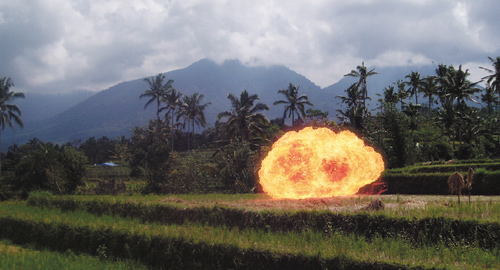
You may think that pulling a matte refers to keying out the blue or green from an effects film shoot (Figure 3.1). True enough, but there are other types of mattes too. Even more common than blue-screen keys are high-contrast, or hi-con, mattes. You create these by maximizing the contrast of a particular channel or area of the image. There are other types of mattes possible as well, such as the elusive difference matte. Chapter 6, “Color Keying,” discusses pulling mattes in depth.
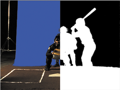
Using an existing alpha channel sounds like a no-brainer, right? The source footage was created with an alpha channel (typically in a 3D animation program); just bring it in as is (Figure 3.2). No worries, done deal, right?
Figure 3.2. This close-up of a computer-generated baseball is split into color (left) and alpha channels.
That's theoretically true, except that After Effects mostly conceals an issue that is quite explicit in other similar software packages (such as Apple's Shake): the interpretation of the alpha channel. Is the edge premultiplied or not, and what do you do in either case? The questions are raised not only when you import the initial image (as you do in After Effects) but also when applying effects to layers with an alpha.
How does After Effects get around this, and is it a good or a bad thing for compositors? For the answer, see the “Alpha Channels and Premultiplication” section later in this chapter.
A mask, by contrast, is a vector shape that determines the opaque and transparent areas of an image (Figure 3.3). Masks are generally created by hand, although After Effects does include a provision to generate them automatically by examining the raster data of an image. You can use the Layer > Create Outlines command, but typically it's not too useful for anything besides stylized motion graphics effects.
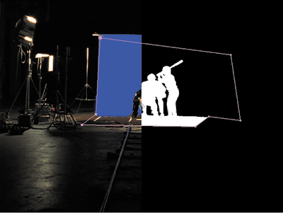
Figure 3.3. In this split-screen view, you can see the garbage matte mask that was added to remove areas of the stage that didn't have a blue screen.
This chapter focuses instead on the basics of creating and combining masks. You can find a follow-up discussion in Chapter 7, “Rotoscoping and Paint,” which focuses specifically on rotoscoping, the art of animating selections over time.
It's even possible to composite without selections at all, instead using blending modes (Add, Multiply, Screen) to combine color channels mathematically, pixel by pixel, in ways that mimic how light and shadow play out in the world (Figure 3.4). You can also use selections combined with blending modes to get the best of both worlds.
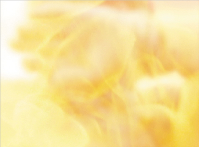
Figure 3.4. Blending modes are the preferred way for compositing elements that are composed of light rather than matter, such as fire.
This chapter goes over the modes that are relevant to effects compositing and gets into the nitty-gritty of what these blending modes are actually doing to the pixel data as they combine it.
Many effects can be used to create transparency effects or to refine the ones you have. Section II discusses these in detail.
As mentioned with blending modes, there is no reason to think that you're barred from combining these techniques, using a garbage matte to clean up a color key or a hi-con matte to enhance the effect of a blending mode. This is very common in advanced effects work, where no two shots are exactly the same and where a single frame or clip can require a variety of approaches.
The real skills here are knowing which approach to apply for a given situation, knowing how to apply it, and knowing when to try something else, either to enhance or to replace what you already have. None of these techniques or approaches is particularly sophisticated by itself, but applying them properly requires a clear vision of what the shot needs and how to supply it.
What exactly is happening in a simple A over B composite? You're just laying one image over another, right? Nothing to it—was obvious from the first time you used Photoshop, right?
For most people, the basic compositing operation is a completely intuitive process that is rarely questioned, but to deal with the crucial part of an A over B composite—the edge detail of layer A—it helps to know what is going on, not only in the world of software, but in the real world as well. The two worlds do not operate the same, but it is the job of the digital world to re-create, as faithfully as possible, what is happening in the natural world.
A bitmap selection channel is one in which each pixel is either fully opaque or fully transparent. This is the type of selection you get if you use, say, the Magic Wand tool in Photoshop. You can feature or blur the resulting edge, but the default selection has no semi-transparent pixels.
This type of selection has its place—say, isolating pixels of one particular color range to change them—but it is not how nature works. A bitmap cannot describe a curve or angle smoothly, and even a straight line with no edge transparency looks unnatural in an image whose goal is realism (Figure 3.5).

But although it's easy enough to see that a bitmap edge does not occur in nature, it's hard to imagine that a feathered alpha does occur—hard objects don't have semi-transparent edges, do they? Of course not. Look at the edge of this page, or anything in the foreground of your field of vision. Do you see semi-transparent edge areas? No.
Not exactly, anyhow. It so happens that semi-transparent edge pixels are the best approximation we have digitally for nature (Figure 3.6), because they solve two problems in translating the world of objects to the world of pixels:
They come closer to describing organic curves.
They approximate the physics of light as it bends around objects.
Figure 3.6. Ahh, that's better. With a proper alpha channel and a one-pixel feather adjustment, even at 400%, the edge does a much better job of describing a smooth, soft curve.
Say what? The first point is easy enough to see and appreciate, but the second one is a doozy, an observation that can be traced back a century to Einstein's annus mirabilus, in which he demonstrated how mass and light are interrelated. Light is bent—slightly—by any amount of mass that it passes. The greater the mass, the higher the amount of bending, right up to the extreme of black holes from which light cannot escape. With most objects, your eye sees a slight, subtle effect.
Geek Alert: The Compositing Formula
When you layer a raster image with semi-transparent alpha over an opaque background image, here's what happens: The foreground pixel values are multiplied by the percentage of transparency, which, if not fully opaque, reduces their value. The background pixels are multiplied by the percentage of opacity (the inverse of opacity), and the two values are added together to produce the composite. Expressed as a formula, it looks like
(Fg * A) + ((1-A)*Bg) = Comp
With real RGB pixel data of R: 185, G: 144, B: 207 in the foreground and R: 80, G: 94, B: 47 in the background, calculating one edge pixel only might look like
[(185, 144, 207) x .6] + [.4 x (80, 94, 47)] = (143, 124, 143)
The result is a weighted blend between the brightness of the foreground and the darker background.
Other effects compositing programs, such as Shake, do not take this operation quite as much for granted the way that After Effects and Photoshop do. You can't simply drag one image over another in a layer stack, you must apply an Over function to create this interaction. Is there a difference? Not until you add to the discussion the operations that go along with an Over, in particular premultiplication, which is detailed later in this chapter.
You can study this effect close-up in a digital photo with no compositing whatsoever (Figures 3.7a, b, and c). In the digital image, you can see areas at the edge of objects that become a wash of color combining the foreground and background. This is caused by the influence of the mass of that object itself on the light (color) coming from behind it.

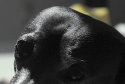
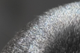
Figure 3.7a, b, and c. Consider a simple digital photo that is not composited (3.7a). When you look closely, you can see that there is a natural softness around the contour of the head despite that it is in sharp focus (3.7b). The effect is even more evident at 400%, if you compare the sharpness (albeit pixilated) of the detail in the fur to the softness of the edge (3.7c). (Images courtesy of Matt Silverman.)
But we're not done with the surprises connected to basic image combination; the way that Opacity edits work in After Effects often takes people by surprise as well, although they can work with it for years without coming face to face with what is counterintuitive about it.
Say you have two identical layers, no alpha/transparency information for either layer. Set each layer to 50% Opacity, and the result should look exactly like either one of the layers at 100%, right?
Wrong (Figure 3.8)! If you've ever heard of Zeno's Paradox, that's something like how opacity is calculated in After Effects, but for good reason.
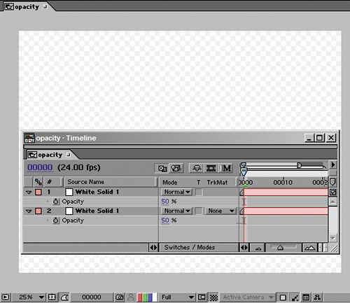
Figure 3.8. Two white solid layers sit one on the other, each at 50%, yet they do not add up to 100% (full) opacity. They add up to 75%, hence the 25% visibility of the checkerboard background.
Zeno was evidently violating the bounds of common sense with his observation. But a lead developer on the After Effects team once described the program's opacity calculations similarly: Imagine you have a light which is 1. You now have half the light showing through (0.5 * 1 = 0.5). Put a 50% transparent object in front of that. Half of the light shows through (0.5 * 0.5 = 0.25), and so on.
Hence, and invoking Zeno's Paradox, After Effects is mimicking how transparency behaves in the real world, which you can try yourself using sheets of vellum or other semi-transparent paper. (This is extra credit, of course!)
Clearly, you don't need to be able to write out the compositing formula to composite, any more than you need to be able to design a car in order to drive one. After Effects helps you by shielding this formula and many other mathematical portions of the compositing operations from your view.
Note
Zeno's Paradox goes something like this: Suppose I wish to cross the room. First, of course, I must cover half the distance. Then, I must cover half the remaining distance. Then, I must cover half the remaining distance. Then I must cover half the remaining distance, and so on forever. The consequence is that I can never get to the other side of the room.
Ignorance is not always bliss, however, when it comes to premultiplication, which After Effects also shields from view when you build a composition. Like Photoshop, After Effects uses non-premultiplied data for the compositing operation, yet it never explicitly tells you (or even lets you find out) how an image is premultiplied and unmultiplied in the image pipeline.
Fortunately, After Effects does an effective job of managing premultiplication under normal circumstances—fortunate because managing it yourself is a tedious process. You just need to know how things can go wrong, the symptoms that show you that something has gone wrong, and what to do to set it right.
Premultiplication exists for one reason only: so that source images look nice, with realistic, anti-aliased edges, before they've been composited.
That's right, we have premultiplication just so that a matted object looks right against a black background when it comes out of, say, your 3D animation program. All premultiplication does is composite the foreground against the background, so that the edges and transparency blend as well into that solid color (typically black) as they would against the final background.
It's not the alpha channel that distinguishes a premultiplied from a straight alpha image, it is the color channels. When you ask After Effects to “guess” how to interpret the footage (on import, by choosing Guess in the Interpret Footage dialog, or using Ctrl+F/Cmd+F), it looks for a solid color background with edge pixels that seem to have had that color multiplied into them.
What does it mean to have the background multiplied into the edge pixels? Revisit “Geek Alert: The Compositing Formula,” but imagine the background value to be 0,0,0. There's your answer. The effect is to darken semi-transparent edge pixels if the background is black, to lighten them if it's white, and to really wreak havoc with them if it's any other color.
The close-ups in Figures 3.9a and b show a section of the same foreground image with the alpha interpreted properly and with it misinterpreted. A misinterpreted alpha either fails to remove the background color from the edge pixels, or removes color that should actually be present.

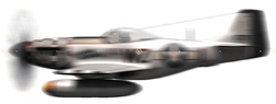
Figure 3.9a and b. Motion Blur clearly reveals the sins of improper premultiply settings. Although there are dark areas in the blur of the properly interpreted foreground, they are consistent with the dark areas of the plane itself (3.9a). The improperly interpreted version has dark matting all around it, including in the areas of the canopy that should be translucent, and around the blur of the propeller (3.9b). You suspect it's wrong simply because it looks bad around the edges.
Why should you care about premultiplication? First of all, because incorrectly managing your alpha channels can cause undesirable fringe artifacts. But just as important, you may find yourself in a situation where those artifacts seem to be presenting themselves although you've carefully managed the process; suddenly your composited elements have black edges around them. Your job depends on getting to the bottom of this. There are two basic ways it can happen:
Note
Most computer-generated images are premultiplied, unless the artist takes specific steps to counteract the process. The Video Output section of the Output Module Settings for items in the Render Queue includes a pull-down to specify whether you render with Straight or Premultiplied alpha; by default, it is set to Premultiplied (Figure 3.10).
An alpha channel is misinterpreted on import (see “Getting it Right on Import”)
A matte is added within a composition and premultiplication isn't accounted for (see “Solving the Problem Internally”)
Unfortunately, users who aren't confident enough to trace the underlying problem often end up resorting to all sorts of strange machinations to try to get rid of the black edge; re-rendering the element against a different color, choking the alpha matte even though it comes from a 3D program and is accurate, and possibly even more frightening and desperate maneuvers.
Most people's ace in the hole if they don't really understand pre-multiplication is the Guess feature that sits next to the premultiplication settings in the Footage Settings dialog. There is also a preference that determines what happens when footage is imported with an alpha channel; if this is set to anything other than Ask User (the default) you may be importing files with alpha channels without knowing what is happening (Figure 3.11).
Figure 3.11. By default, the import preferences are set to ask the user how to interpret an alpha channel, which is a good thing, generally speaking, as a check against errors. If you're not sure about the appropriate setting, you can click on the Guess button, which typically can determine the type of channel. If it cannot guess confidently, it beeps.
Is Guess ever wrong? Yes, it can be, if the factors it expects in a premultiplied alpha are there in a straight image, or vice versa. Thus it is best not to automate this process, if only so that you're able to hear the beep. In the case of a premultiplied image, After Effects attempts to guess not only the setting but also the color of the background; generally this will be black or white, but watch out for situations where an artist has become creative and rendered against canary yellow or powder blue. For that reason, there is an eyedropper adjacent to the Matted with Color setting (Figure 3.11). When in doubt, look at your footage without the alpha applied: If you see a solid background that is neither pure black or white and After Effects isn't detecting it, use the eyedropper.
Note
To see footage that was imported with a premultiplied alpha displayed in straight alpha mode (with edge transparency removed) use this shortcut in the Layer/Composition window: Alt+Shift+4 (Option+Shift+4).
Fundamentally, though, as an effects compositor you need to be able to examine your images and spot the symptoms of a misinterpreted alpha: dark or bright fringing in the semi-opaque edges of your foreground.
The really gnarly fact is that premultiplication errors can be introduced within the After Effects pipeline. Usually this happens when you apply a selection as a track matte to footage (described in more detail toward the end of this chapter), and After Effects, of course, doesn't anticipate premultiplication. If the sequence was rendered with premultiplication but the alpha channel was created on a separate pass, as a separate file, for example, you would apply that alpha using a track matte. After Effects would have no idea that the image was premultiplied, however, because the color channels came in through the back door, as it were, without an alpha.
If you see fringing in your edges and need to solve it internally in After Effects, there is a tool to help: the Remove Color Matting effect (Figures 3.12a and b). This effect has one setting only, for background color, because all it does is apply the unpremultiply calculation (the antidote to premultiplication) in the same manner that it would be applied in the Footage Settings.
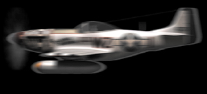
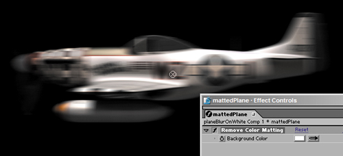
Figure 3.12a and b. In 3.12a, the plane against the white background had an alpha applied via a track matte without premultiplication removed, revealing white fringing, which is clear here against the black. With the color set to pure white, the Remove Color Matting effect corrects the problem (3.12b), but only once the color and track matte layers have been pre-composed.
Although hand-created and animated for the most part, masks open up all kinds of possibilities in After Effects. Masks are the principal method for defining transparency regions in a clip without regard to actual pixels, because they are vector shapes. This section lays down the basics for smart use of masks.
There are three tools for creating masks: two shape tools and the Pen. To activate the Rectangular Mask tool, use the keyboard shortcut Q; press Q again to toggle the tool to the Elliptical Mask tool. If your mask doesn't conform well to a rectangle or an ellipse, you can draw it point by point with the Pen tool (G).
Whether you draw the mask in the Composition window or the Layer window is up to you. It is somewhere between difficult and impossible to draw or see a mask accurately in the Composition window if, say, the layer was offset and rotated in 3D space, but if you want to see the layer over its background, you need to have the Composition window open. With enough monitor space, an ideal compromise is to keep both windows open side by side, working in the Layer window and watching the Composition window for live updates.
Remember that your target shape doesn't have to be an ellipse to benefit from starting by drawing an ellipse. Indeed, if the shape calls for a perfectly circular curve on one side, you might do well to draw an ellipse (holding down Shift to make it perfectly circular) and then editing other sides of it with the Pen tool.
Note
If you need other common primitive shapes—a rectangle with rounded corners, a hexagon, or the like—you're best off drawing the shape in Adobe Illustrator, then copying and pasting it. This, however, will not work unless the preferences in Illustrator are set properly. Under the File Handling & Clipboard preference, choose AICB with Preserve Paths checked. This is not the default. You can also select and copy paths in Photoshop for use as masks.
When drawing a rectangle or ellipse
Double-click the Mask tool (in the Tools palette) to set the boundaries of the mask to match those of the layer.
Use Shift to constrain the shape and Ctrl/Cmd to draw the shape from the center rather than from a corner.
Try the Mask Shape dialog if you need to set the boundaries to exact dimensions and can't do it visually. Although this dialog's use is quite limited, you access it by clicking the underlined word “Shape” under Mask options (highlight the layer and click M to reveal it).
Double-click a point on the shape to activate Free Transform mode, which enables you to offset, rotate, or scale the entire mask shape (Figure 3.13). As always, hold down Shift to keep the scale proportional, snap the rotation to 45 degree increments, or constrain movement to one axis.
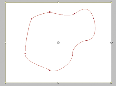
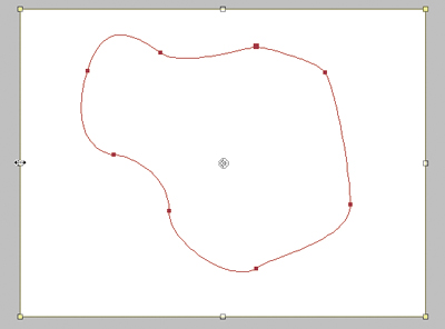
Figure 3.13. Flipping a custom mask symmetrically on one axis is no easy trick in After Effects. Holding down the Shift key scales both axes proportionally, which is not usually what you want. Instead, with View > Show Grid enabled and View Snap to Grid turned on, double-click the Rectangular Mask tool to create a mask that is the size of the layer. Select both masks in the timeline, and double-click a point on one of the masks to set the Free Transform tool. Now drag the handles at either side of the image and swap their positions, deleting the layer-sized mask when you're done.
Highlighting a layer with a mask and pressing the M key twice in rapid succession reveals the full Mask options for that layer. Some tips for those are
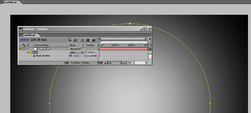
Feather is set for the entire mask and operates in both directions (to the inside and outside of the mask shape); there is no way around these defaults. All kinds of lighting, smoke, and glow effects can begin with a masked solid that is heavily feathered. In other words, the feather setting is approximately half the width of the mask at its narrowest crossing, meaning the masked solid is now a big soft gradient (Figure 3.14).
Pressing the F key reveals only the Mask Feather property in the timeline.
A hidden gem is Mask Expansion: You can use it to expand or, with a negative value, to contract the mask area. This has all sorts of uses, including creating an edge mask using one mask duplicated into two, each with a Mask Expansion value that is the inverse of the other, and the inner mask subtracted from the outer.
Keyboard shortcuts are a big part of eliminating a lot of the fuss and bother that comes with masking in After Effects.
By default, the Pen tool draws Bezier curves, and in After Effects you can do everything you need to create a mask by keeping the Pen tool active throughout the mask edit.
I sometimes draw a Bezier mask first as straight lines only, clicking to place points at key transitions and corners. Once I've completed the basic mask shape, with the Pen tool still active, I can go back point by point and edit the shape, because I have instant access to all of the mask shortcuts:
Clicking on a point with the Pen tool active deletes it.
Clicking on a segment between points with the Pen tool active adds a point.
Alt/Option-clicking on a point with the Pen tool enables the Convert Vertex tool: Apply it to a point with no handles, and you can drag out to create handles. Apply it to a point with handles, and you cancel the handles.
Clicking on a Bezier handle with the Pen tool breaks the center point of the Bezier, enabling you to adjust the handles individually; Alt/Option-clicking on a handle restores a linear connection between the handles.
Context-clicking on the mask shape with the Pen tool (or the Selection tool, for that matter) enables the context menu of options for that mask, including all of its settings on the timeline, the ability to specify a First Vertex, and Motion Blur settings for the mask, which can be unlocked from the layer itself.
Note
As with most selectable UI elements in After Effects, pressing F2 or Ctrl+Shift+A (Cmd+Shift+A) deselects the active mask. This is handy when you're done drawing one mask and want to create the next one without switching tools.
Only when you want to double-click to free transform the entire mask is it necessary to switch to the Selection tool, which you can do either by pressing V or by holding down Ctrl/Cmd while you double-click a vertex. The Ctrl/Cmd key toggles back and forth between the Pen and Selection tools, regardless of which one is currently active.
By default, all masks are drawn in Add mode, meaning that the contents of the mask are added to the layer selection, and the area outside all of the masks is excluded. There are other options for combining them, however; the five primary mask modes are
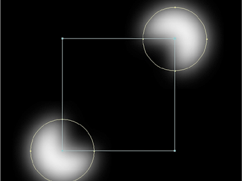
Add: The default mode; adds the density (luminance) values to the image as a whole, including masks higher in the stack (Figure 3.15)
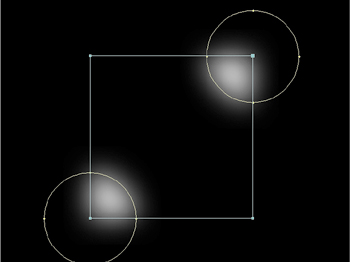
Subtract: Subtracts density (luminance) values from masks higher in the stack or from the image as a whole if no other masks precede it (Figure 3.16)
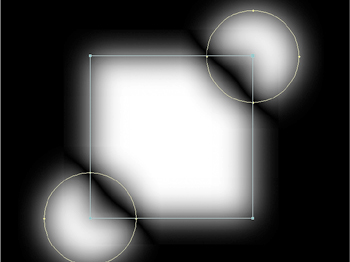
Intersect: Combines only the areas of the density that overlap with masks higher in the stack (Figure 3.17)
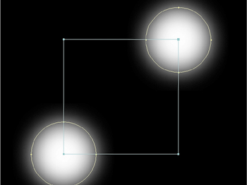
Difference: Subtracts overlapping areas. (Figure 3.18)
None: Has no effect on the image whatsoever; it can be useful as a placeholder or for effects that use masks (Figure 3.19)
Particularly when rotoscoping (masking an animated shape) it is very wise to take advantage of using multiple masks, for one simple reason: The more points you have to keep track of on a given frame, the more likely you'll have to add a keyframe and the more likely you'll lose track of a point. With multiple masks there is far more forgiveness for small errors and fewer keyframes per mask are needed to complete the job. This topic is explored in greater detail in Chapter 7, “Rotoscoping and Paint.”
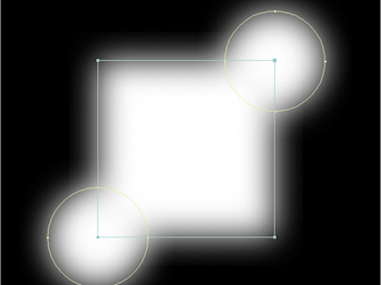
When combining masks that have semi-transparent areas, either because the opacity of the masks is less than 100% or, as in the examples shown here, because the edges are heavily feathered, you may not always want the densities to have a completely linear relationship in the overlapping areas. That's when Lighten and Darken modes come into play.
Figures 3.20a and b show the result of using each of these modes; they prevent mask densities from building up the way that they do with the other modes. No pixel within the combined masks will have a value that is not already represented in one of the overlapping masks; either the lighter or the darker of the two will be represented.
Figure 3.20a and b. With a lighten (3.20a) or a darken (3.20b) mask, the transparency values are chosen either from the mask set to this mode or those overlapping it, depending on which has the lighter (higher) or darker (lower) values.
Keep these in mind when combining multiple feathered or semi-transparent masks. Remember that mask modes apply to the layers above them, so these modes should be applied as each overlapping mask is added, not to the top mask in the stack.
A few features in After Effects exist specifically to help you manage multiple masks in a single layer.
One is Cycle Mask Colors, which is tucked away in the User Interface Colors section of Preferences. When Cycle Mask Colors is off, your masks are created in the same color (the mask itself and its swatch in the timeline) each time. To change it, you click the swatch. With Cycle Mask Colors checked on, which I recommend, the mask colors vary on their own.
Note
Don't forget that you can name masks by highlighting them in the timeline, pressing Return, and typing in a new name. The names don't come along when you copy and paste the layers, unfortunately, but they're still useful.
Also, when editing overlapping masks, you may find it helpful to use the context menu to lock and hide other masks. Context-click on the mask, and choose Lock Other Masks; now you can edit the active mask only. Context-click again, and choose Hide Locked Masks; this time your view is uncluttered as well.
Bug Alert, or Not?
Does a bug still count as a bug if the development team knows about it and has decided to leave it as-is to be backward-compatible? I'll let you be the judge. Say there's one part of an overlaid element that you want to mask and reduce to partial opacity, say 50%.
You create a mask for the area to be dialed back, set it to Subtract, and set Mask Opacity to 50%. But instead of the anticipated result, displaying the layer at full opacity and the masked area at 50%, the masked area is subtracted 100% and the rest of the layer displays at 50% opacity!
This is the identical result to applying the same mask in Add mode with Invert checked, only in that case the behavior is at least anticipated.
The workaround is to add a mask at the top of the stack, giving the mask the dimensions of the entire layer (double-click the Rectangular Mask tool). The Subtract mask will now work properly relative to this first mask, set to Add mode.
Putting masks in motion for visual effects work is also known as rotoscoping, which is covered in greater depth in Chapter 7. There are all kinds of uses for masks, however, and that chapter is fairly specialized, so here is an overview of some things to pay attention to when putting a mask in motion.
You can set a temporal ease on a mask keyframe, but you have no corresponding spatial curves with masks. Each point travels in a straight line to its position in the following keyframe.
This means that to precisely mask an object traveling in an arc, you need to set a lot more keyframes than for an object traveling in a single direction.
The real bummer about mask keyframes is that you can't select a group of them and translate the mask; as soon as you move, rotate, or scale it, your selection snaps to the current keyframe only.
There is a workaround. You can duplicate the layer being masked and use it as an alpha track matte for an unmasked source of the same layer, in which case you're free to transform (or even motion track) the duplicate using the normal layer transforms. It's not a perfect solution by any means, but it is often useful and hardly anyone thinks of it.
You can freely copy mask shapes from one source (a different mask, a different keyframe in the same mask animation, Illustrator, or Photoshop) and paste them into an existing mask channel. You just have to follow some rather strict rules that depend on the situation:
With no keyframes involved in the source or target: Selecting the mask itself and pasting it to another layer automatically applies it as-is to a new mask or to any mask that is selected.
Source mask has Mask Shape keyframes, but target has none: Highlighting the mask (not the specific keyframes) and pasting creates a new mask as if pasting from time 0. Highlighting any or all Mask Shape keyframes pastes a new mask with keyframes starting at the current time.
Target layer has masks with or without keyframes: To paste Mask Shape keyframes into a particular mask at a particular time, highlight the target mask before pasting. Highlighting the target Mask Shape property highlights any keyframes and replaces them (not usually what you want).
In all cases, if the target layer is a different size or dimension from the source, the mask stretches to maintain its relationship to the layer boundaries.
In many situations, pasting Mask Shape keyframes blindly in this manner is not what you're after, but a rather obscure feature in the Layer window will help you. The Target pull-down along the bottom of the window has a unique function: When you choose an existing mask as the target, you can start drawing a new mask anywhere in frame and it will replace the shape in the target mask layer (Figure 3.21).
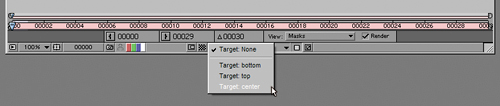
Figure 3.21. This pull-down menu at the bottom of the Layer window makes it easy for you to create a mask shape from scratch, replacing the shape in the target mask. If the target mask has keyframes, After Effects creates a new keyframe wherever you draw in a new shape for that mask.
Note
The Smart Mask Interpolation tool (available via a palette found in the Window menu) is designed to smooth transitions between two radically different shapes. It's useful for stylized motion graphics of detailed masks transitioning from one to the next, but less useful for effects masking and rotoscoping because it's a bit too automated. The result, while sometimes pleasing, doesn't usually obviate the need to more carefully keyframe an accurate mask transition.
When pasting in shapes or radically changing the existing mask by adding and deleting points, you may run into the issue of how the points line up. Hidden away in the mask context menu, and available only with a single vertex of the mask selected, is the Set First Vertex command. If you are having problems with mask points twisting around to a mismatched point during an interpolation, setting the First Vertex to two points that definitely correspond should help straighten things out. It also can be necessary for effects that rely on mask shapes, such as the Reshape tool (described in Chapter 7).
After Effects includes 34 blending modes, each created with a specific purpose (Figure 3.22). For effects work, however, the majority of them are not particularly recommended. In fact, traditional optical compositing would effectively include only two of them: Add and Multiply.
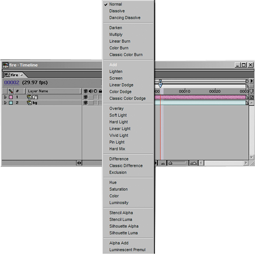
So that's it? Use these two or none at all? Not quite—I'll point out a few other useful modes as well. Once you understand how your options work, you can make informed compositing decisions, rather than lazily playing Go Fish by trying one mode after the other until you see something you kind of like.
Note
The mathematical descriptions of blending use values normalized to 1; in other words, the full range of pixel values is 0 to 1 instead of 0 to 255, as it typically appears in your color controls. A medium gray on any channel is 0.5 instead of 128, pure white is 1, and pure black is 0 (Figure 3.23). This makes it much simpler to show the calculations that are actually used to create the blended pixels, because the internal math typically is based this way. For information about overbright values, which have a value greater than 1,see Chapter 11, “Issues Specific to Film and HDR Images.”
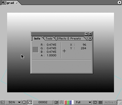
Figure 3.23. The Info palette can display pixel values in several different modes, including decimal values, shown here with the cursor over a medium gray. The values are normalized to a maximum luminance value of 1.0 and a minimum of 0.0, which make calculations more straightforward than 0 to 255, the standard 8-bit range. Select a color mode for the Info palette via its wing menu; whatever mode you select is thereafter also used by the Adobe color picker.
Remember, blending modes are all based on mathematical operations for combining pixels in the layer containing the given blending mode and the pixels behind it—either below it in the stack, if all the layers are 2D, or positioned behind it in 3D space, if all the layers are 3D.
To help you understand what the various blending modes are doing, Figures 3.24 through 3.30 show you what happens when a masked gradient is blended with its exact inverse. Remember that color operations are fundamentally no different than grayscale, except that they happen via three channels instead of one.
Figure 3.24. Compare Figures 3.25 through 3.30 to this one, which shows a masked section of a gradient over its exact inverse. Blending here is set to Normal.
Figure 3.25. The same combination with Add mode applied to the masked foreground area, which becomes full white as each pixel in the background is added to its inverse in the foreground.
Figure 3.26. Screening results in combined pixels that are not as bright as with Add, but which are combined in a similarly linear manner resulting in a flat color.

Figure 3.27. Multiplying a value with its inverse causes it to be zero or full black. This is like having the two gradients on two separate pieces of film and laying one over the other, making the combination darker because less light passes through the denser (darker) areas.
Figure 3.28. Overlay is a combination of Screen and Multiply; areas of the background below 50% brightness are multiplied, those above 50% are screened.
Figure 3.29. The inverse of Overlay: This time areas of the foreground below 50% brightness are multiplied, those above 50% are screened.
Figure 3.30. Difference bases the luminance of the foreground pixels on the amount of difference between the foreground and background source. In this case, pixels along the vertical center have no difference and are black, with the difference increasing as pixels move toward the upper and lower edges.
Add and Screen modes both brighten the image. Screen typically yields a subtler effect than Add, which results in brighter values overall.
Add mode is every bit as simple as it sounds; the formula is
newPixel = A + B
where A is a pixel from the foreground layer and B is a background pixel (although they are obviously interchangeable in this formula). The result is clipped at 1 for normal 8- and 16-bit pixels; any pixels that add up to a value of more than 1 take the value of 1, full white.
Note
What is the difference between Add and Linear Dodge? The name! Open Photoshop and you'll notice it contains no blending mode called Add. Apparently Photoshop lacks the legal rights to use this term, hence Linear Dodge, which exists in After Effects only to match Photoshop.
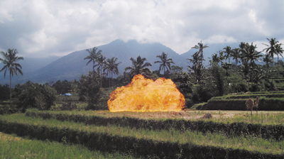
This mode is used a lot; it brightens the overall image, but black in the foreground becomes transparent, effectively adding a value of 0 to the background. It is useful for laying fire and explosion elements shot in negative space (against black) into a scene, adding noise or grain to an element, or any other element that is made up of light and texture (Figures 3.31a, b, and c).
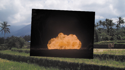
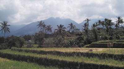
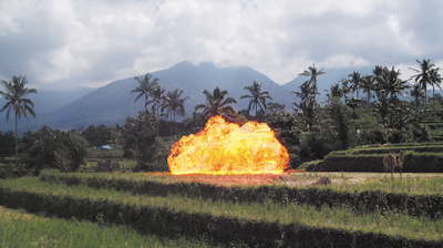
Figure 3.31a, b, and c. Add mode takes the source foreground element, the fire shot against a black background shown in 3.31a, and adds its pixel values channel by channel to the background (3.31b), causing the pure black pixels to disappear completely (3.31c).
Screen mode has an influence similar to Add mode's, but via a slightly different formula. The pixel values are inverted, multiplied together, and the result is inverted:
newPixel = 1–((1–A) * (1–B))
Note
Because Screen depends on no values being greater than 1, do not use it in a floating-point image pipeline that includes the possibility of pixel values over 1, such as eLin (Chapter 11).
Note that with this formula, fully white pixels stay white, fully black pixels stay black, but a mid-range pixel (0.5) takes on a brighter value (0.75), just not as bright as would be with Add (1).
You use Screen much like Add. Screen is most useful in situations where Add would blow out the highlights too much—glints, flares, glow passes, and so on (Figure 3.32).
Multiply is another mode that is as simple as it sounds; it uses the formula
newPixel = A * B
This would seem to make the values much higher until you recollect that we are dealing only with values between 0 and 1. Multiplying them together, therefore, actually has the effect of reducing midrange pixels and darkening an image overall, although pixels that are full white in both images remain full white.
In optical compositing (the way this was all done before we had computers) the equivalent of multiply was layering two images, one over the other, combining their densities such that the dark areas of one image held out light from the other image.
Multiply literally has the inverse effect of Screen mode, darkening the midrange values of one image with another. It is useful in cases where you have dark tones that you want to include in an image without replacing the lighter tones as much, for example to layer in texture, shadow, or dark fog to a background (Figure 3.33).

Overlay uses the bottom layer to determine whether to screen or multiply. If the top layer is lighter than 50%, it is screened. Below 50%, it is multiplied. Hard Light does the same, only using the top layer to determine whether to screen or multiply, so the two are inverse effects. Reversing layer order and swapping Overlay for Hard Light yields an identical result.
These modes, along with Linear and Vivid Light, can be most useful for combining a layer that is predominantly color with another layer that is predominantly luminance, or contrast detail (Figure 3.34). This is how you create textures; for example, a lot of the lava texturing in the Level 4 sequence of Spy Kids 3–D was created by combining a hand-painted color heat map with moving fractal noise patterns using Hard Light.
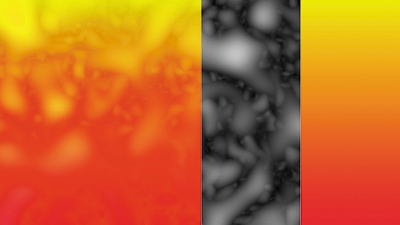
Figure 3.34. Overlay and its inverse, Hard Light, are useful for combining color and texture. Here, an instant lava lamp texture was created using the components shown at the right: a solid with Fractal Noise applied set to Overlay mode on top of a red-to-yellow gradient.
This type of usage is fine, but don't start fishing in the various Light modes when combining images. They don't work with overbright levels (explored in Chapter 11), and this method of adjusting images is a warning sign that you haven't thought things through in terms of what you're trying to do.
Difference is a subtraction mode that inverts a pixel in the background according to how bright the foreground pixel is. There is one very specific use for Difference that is never rendered: You can line up two identical layers using this mode. When all of the pixels line up properly, layer details disappear.
The Hue, Saturation, and Brightness modes each combine the given value from the foreground layer with the other two from the background layer. Saturation applies the foreground saturation to the background hue and luminance values, Hue combines the foreground hue with the background saturation and luminance, and Brightness uses the foreground luminance in combination with the hue and saturation of the background.
Color takes both the hue and saturation of the top layer, using only the luminance from the underlying background (Figure 3.35).
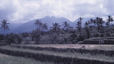
Figure 3.35. Setting a deep-blue-colored solid to Color mode and overlaying it on the plate footage has the effect of tinting the colors in the image blue. Subtler uses of this mode are explored in Chapter 12, “Working with Light.”
Keep these modes in mind as a shortcut to channel operations in which you might want the color from a foreground combined with the detail (luminance) of the existing background.
The Stencil and Silhouette blending modes apply transparency information to all of the layers below them in the composition. The Stencil modes use the light pixels, and Silhouette the dark pixels, of either the Alpha or Luminance values to determine the areas that remain visible in the layers below the current layer.
You should keep these in mind for that rare occasion where they save you extra setup work.
Alpha Add and Luminescent Premultiply are special-case blending modes that affect semi-transparent edge pixels only.
Have you ever tried matting a layer with an alpha channel over the same layer with the alpha channel inverted? Figures 3.36a through d show the typical result: a semi-opaque line tracing the edge of the alpha, where the pixels remain semi-transparent because they are blended together in the same manner as semi-opaque layers. Alpha Add adds the actual values of the alpha pixels without compensating for the opacity effect, so two 50% opaque pixels become 100% opaque.
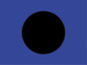
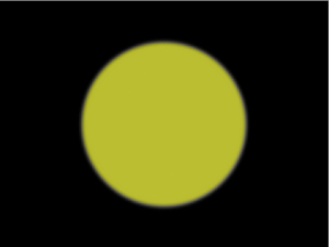
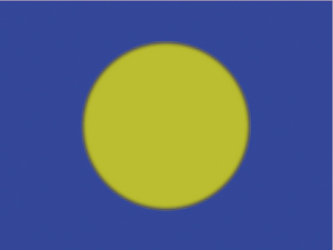
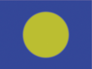
Figure 3.36a through d. (left to right) Laying a matted object over a background with the inverse matte seems as though it should result in a fully opaque image (3.36a, b). Instead, edge pixels become semi-transparent (3.36c). Alpha Add does just what the title implies, adding the alpha values together so that inverse mattes total up to 100% throughout the image (3.36d).
Why would you combine a layer with itself, inverting the alpha? You probably wouldn't. But you might combine two layers with overlapping transparency that should work this way—for example, two parts of the same layer.
Luminescent Premultiply is an alternative method of removing premultiplication from source footage, retaining bright values that would otherwise be clipped. Premultiplication over black causes all semi-transparent pixels to become darker; removing the black values while adding transparency, which is what removing premultiplication does, can cause them to appear dimmer than they should. This is useful for bright overlaid elements that come in with alpha channels and premultiplication, such as flares and explosions; you can set the footage to interpret as Straight on import and use this mode instead of Normal to overlay the element. It's another trick to keep in your arsenal should you ever see the symptoms (dim translucent elements) for which it is recommended.
Track mattes are the primary method by which you can use the alpha or luminance information of one layer to set the transparency of another layer (Figure 3.37). This is actually the normal way to apply a matte channel in many compositing applications, which don't have the concept of the alpha channel so firmly integrated into the overall pipeline as After Effects.
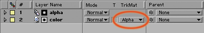
Figure 3.37. A basic alpha track matte setup: The alpha of layer 1 is set as the alpha of layer 2 via the highlighted pull-down menu. The small icons just to the left of the layer names help remind you that this relationship has been set up, and which is the color layer and which is the matte.
The perceptual difference between an alpha channel and a track matte isn't, for the most part, too difficult to grasp. In both cases, you have pixels with a value (in 8-bit color space) between 0 and 255, whether they are color or grayscale alpha pixels. That any image would be interchangeable with the alpha channel shouldn't be too shocking; even if you're using the luminance of a full-color image, After Effects simply averages the 0 to 255 value of the three color channels into one value. The principle doesn't even change in 16-bit color—it's just the same range of values, with finer increments, being sampled.
You set a track matte by placing the layer that contains the transparency data directly above its target layer in the timeline and choosing one of the four options from the Track Matte pull-down menu:
Alpha Matte: Uses the alpha channel of the track matte layer as if it were the alpha of the underlying target layer
Alpha Inverted Matte: Does the same as Alpha Matte but inverts the result, so that the lighter areas of the alpha are transparent and the darker areas are opaque
Luma Matte: Uses the luminance data of the track matte layer (the relative brightness of the red, green, and blue channels combined) as if it were the alpha of the underlying target layer
Luma Inverted Matte: Does the same as Luma Matte but inverts the result, so that the lighter areas of the alpha are transparent and the darker areas are opaque
By default, the source layer for the track matte (the upper of the two) has its visibility turned off when you set the track matte, which is almost always what you want. This sets the track matte with a single click to the Track Matte pull-down menu. If you need to adjust the source after setting it, you can always temporarily turn it back on; just remember to turn it back off when you're finished.
Track mattes are not the only way to apply alpha or luminance data to the transparency of a layer, but they're the clearest and most straightforward way. They help you out of a lot of jams in which creating a selection via other means would be inconvenient or in which mask or matte features constrain you.
For example, it's not possible to track a mask in After Effects. But it is possible to apply the mask to a track matte instead, and then to track that layer (instead of the mask itself). Chapter 8, “Effective Motion Tracking,” discusses this in detail.
In Chapter 6 you will learn of the many ways to pull a key, including hi-con mattes. Some of these methods apply their results directly to the alpha channel of the target layer, but others cannot. Additionally, specific operations such as blue-screen keying can change the color of the source (automatically removing blue spill from the foreground); applying the key via a track matte to a duplicate clean source instead is an effective workaround if you want the matte but not the despill.
Unlike with parented layers (described in Chapter 2, “The Timeline”), selecting a track matte layer does not lock it to the current layer. In fact, setting a track matte means that no matter which layer is next higher in the stack, that layer is the source of the matte. Thus, accidentally moving a layer in between a layer and its track matte can cause easily solvable but, nonetheless, disastrous results.
When you duplicate a layer with a track matte activated (Ctrl+D/Cmd+D), After Effects automatically duplicates it above the matte layer or two layers above the current layer. If you duplicate the matte layer at the same time, the duplicate will also move up two layers, so that all layers preserve their proper track mattes (Figure 3.38). That's good. What's bad is if you forget to duplicate both layers, because the track matte remains active in the duplicate layer, even if it has been duplicated to the top of the stack, and you can't see that it's active.
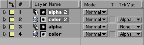
Figure 3.38. Selecting and duplicating the layers from Figure 3.37 creates two new layers that leapfrog above the previous layers to maintain the proper color/matte relationship in the source and duplicate layers.
If the layer to which the track matte is applied already has an alpha channel, then the new selection area created by the track matte will be opaque only in the areas that are opaque in both mattes. So applying a track matte in this situation is like making a subselection of the current selection.
Also tricky to work out with track mattes is the render order: Sometimes adjustments and effects that you apply to the matte layer are applied to the target matte, and sometimes you must first pre-compose to get the applied effects and adjustments.
And what happens if you apply a track matte to a track matte? It's actually hard to say; sometimes it will work, sometimes not. The user interface does not prohibit this behavior so you can try it, but a better idea is probably to pre-compose the first instance of track matting and apply the second track matte to that nested composition.
The next chapter, “Optimizing the Pipeline,” looks in depth at solving issues related to render order, and you'll begin to use After Effects as a visual problem-solving tool for these issues.