
Prestressed fiber-reinforced polymer (FRP) composites for concrete structures in flexure: fundamentals to applications
Y.J. Kim, University of Colorado, Denver, USA
M.F. Green, Queen’s University, Canada
R. Gordon Wight, Royal Military College of Canada, Canada
Abstract:
This chapter presents a comprehensive overview of prestressed fiber-reinforced polymer (FRP) composites for concrete structures. Of interest are the prestressing methods and flexural responses of such structures. This state-of-the-art review provides a synthesis of all existing prestressing applications for reinforcing or strengthening concrete members, including bonded and unbonded FRP composites. The review examines published codes and design manuals with their limitations, prestressing operation, failure modes, design methods, bond characteristics, and deformability (or ductility) of various prestressed FRP applications. Current research needs are discussed to further improve an understanding of the behavior and application of prestressed FRP composites for concrete structures.
Key words
application methods; bonding; ductility; fiber-reinforced polymer (FRP); prestressed concrete; reviews
2.1 Introduction
Prestressed concrete structures may suffer from damage of steel strands, including insufficient load-carrying capacity and degraded serviceability (e.g., large deflection and excessive cracks). Corrosion of steel strands may be the most significant contribution to the initiation and acceleration of damage in prestressed concrete members. To overcome this critical problem, various efforts have been made: for example, galvanized or epoxy-coated steel, and polymer concrete or low permeability concrete to reduce pores of the concrete (Toutanji and Saafi, 1999). None of these methods, however, effectively resolved corrosion problems.
Recent advances in materials technologies have resulted in an alternative reinforcing material, FRP composites. This chapter presents a synthesis of recent advances in prestressed FRP composites for concrete members subjected to flexural load, from fundamentals to applications. Focus is on the practical implementation of prestressed FRPs to better transfer the emerging technologies to practicing engineers and research professionals, including various prestressing operations and corresponding flexural responses of FRP-prestressed members. Current research needs to fill the gap between theory and practice are also discussed.
2.2 Types and characteristics of fiber-reinforced polymer (FRP) composites
Typical FRP composites consist of unidirectional fibers and a matrix resin. The fibers provide the load-carrying capacity of the composite. The matrix resin binds the fibers and transfers applied stresses between the fibers. Typical matrix resins include polyester, vinylester, and epoxy (Dolan, 1999). Two types of FRP reinforcement are currently available for concrete structures, namely FRP bars and laminates. A typical FRP tendon consists of 40% resin and 60% fiber (Dolan, 1999), and FRP laminates have 20–35% resin and 65–80% fiber (Meier, 1995; Wight et al., 2001; El-Hacha et al., 2003). Fiber content controls the mechanical properties of FRP composites. It should be noted that, for FRP-sheet applications, volume–fraction ratios may slightly change depending upon wet-lay-up (i.e., dry fibers and wet resins are incorporated on site and cured). In this case, the contribution of resin to the load-carrying capacity of FRP composites can be ignored (MBrace, 1998).
For infrastructure applications, three types of FRP composites are primarily used: aramid FRP (AFRP), glass FRP (GFRP), and carbon FRP (CFRP) (Bakis et al., 2002; Teng et al., 2003). The advantages of these FRP composites are non-corrosive characteristics, light weight, high tensile strength, low relaxation, good fatigue resistance, reduced maintenance costs, and ease of handling (Grace and Abdel-Sayed, 2000; Zhang et al., 2000; Bakis et al., 2002; Ghallab and Beeby, 2005; Youakim and Karbhari, 2007; Kim and Heffernan, 2008).
The benefits of prestressed FRP composites include the efficient use of FRP materials, reduced deflection, controlled cracks, active load-carrying mechanism, restored prestress losses in a prestressed concrete beam, improved cracking and yield loads of strengthened beams, and stress redistribution (Meier, 1995; Wight et al., 2001; Kim et al., 2007a, 2008). The most notable benefits of FRP composites for prestressed concrete applications are their non-corrosive characteristics and high tensile strength. Taking into account the high tensile strength of FRP composites (e.g., 4–10 times greater than yield strength of reinforcing steel and comparable to prestressing steel strands, as shown in Table 2.1), a prestress may be applied to efficiently use the material strength. The most remarkable difference between concrete beams with prestressed FRP composites and steel-prestressed concrete beams is the absence of yield load, because of the linear behavior of FRP composites until failure occurs. The failure of the beams with prestressed FRP composites may, thus, be substantiated by either concrete crushing or FRP rupture.
Table 2.1
Various FRP products for prestressing applications reported by the manufacturers
| Typical property | Steel | CFRP | AFRP | |||||||
| Type | Rebar | Tendon | Tendon | Sheet/laminate | Tendon | |||||
| Product | Generic | Generic | Leadline | CFCC | MBrace (CF-130) | Replark | Tyfo UC | Arapree | Parafil | Technora |
| Density (g/cm3) | 7.85 | 7.85 | 1.5 | 1.5 | 300 g/m2 | 200 g/m2 | 1.81 | 1.25 | 1.44 | 1.3 |
| Longitudinal tensile strength (MPa) | 400* | 1860 | 2550 | 2100 | 3800 | 1480 | 2510 | 1500 | 1900 | 2100 |
| Longitudinal tensile modulus (GPa) | 200 | 195 | 150 | 137 | 227 | 144 | 139 | 64 | 130 | 54 |
| Poisson’s ratio | 0.3 | 0.3 | 0.27 | – | – | 0.3 | – | 0.38 | – | 0.35 |
| Ultimate strain (%) | 0.2* | >3.5 | 1.5 | 1.57 | 1.67 | 1.4 | 1.8 | 2.4 | 1.7 | 3.8 |
| Longitudinal coefficient of thermal expansion (CTE) (× 10−6/°C) | 12 | 12 | −0.9 | 0.5 | −0.38 | 0.7 × 10⁻⁴ | – | −2 | – | −3 |
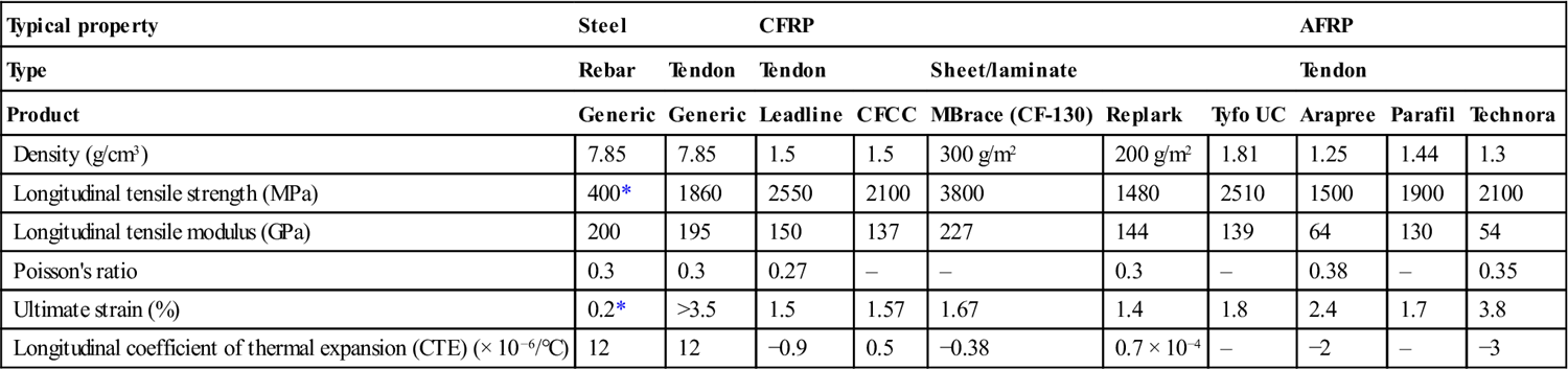
*Yield property.
AFRP materials are sensitive to the exposure of ultraviolet rays and thus they may be appropriate for internal prestressing application (McKay and Erki, 1993). AFRP composites show good fatigue resistance (Meier, 1995; Pisani, 1998); however, their time-dependent behavior is an important consideration for prestressing applications, taking into account their large relaxation characteristics and creep (McKay and Erki, 1993; Zhang et al., 2000). For example, typical relaxation losses of AFRP tendons are 6–18% in a 100 year design life (Dolan, 1989) which are significantly greater than those of steel strands, having approximately 3% of relaxation losses in 100 years. GFRP composites are limitedly used in prestressing application because of their poor resistance to creep (ACI, 2004; ISIS, 2007; Youakim and Karbhari, 2007). GFRP tendons show a typical strength decrease of 30% in 100 years (Pisani, 1998). It should be noted that an additional strength reduction of GFRP tendons may occur if the tendons are embedded in concrete because of their inadequate performance in an alkaline environment (Dolan, 1999). CFRP composites exhibit high strength (over 2100 MPa), low density (typically 1.5 g/cm3), and high temperature resistance, as shown in Table 2.1. CFRP materials also include excellent time-dependent behavior (e.g., no creep (Pisani, 1998)). However, material costs of CFRP are higher than those of GFRP and AFRP.
2.3 Using FRP composites in structures: design and applications
Despite the advantages of FRP composites and potential for cost-saving solutions, the application of prestressed FRP composites in practice is still in an early stage. This is attributed to the fact that practicing engineers and designers may not be familiar with such emerging prestressing technologies. Recently published code and design manuals reflect the significance of prestressed FRP composites for concrete structures.
fib Task Group 9.3 (fib, 2001) regards the application of prestressed FRP reinforcement as a special technique and addresses a number of advantages. The manual, however, does not specifically provide design guidelines for use of prestressed FRP composites. ACI 440.4R-04 (ACI, 2004) and ISIS Canada (ISIS, 2007) provide comprehensive design considerations for concrete structures using prestressed FRP composites, including flexural and shear design as well as serviceability. The Italian design manual CNR-DT200 (NRC, 2004) does not include specific provisions for prestressed FRP composites. The Canadian Highway Bridge Design Code (CHBDC, 2006) specifications include brief guidelines of prestressed FRP tendons for bridge superstructure (e.g., maximum permissible stresses in FRP tendons at jacking and transfer for concrete members).
Although some codes and design manuals have recently been published to aid use of prestressed FRP composites for concrete structures (ACI, 2004; CHBDC, 2006; ISIS, 2007), there still exists a dearth of understanding of the detailed structural behavior of FRP-prestressed concrete members. In addition, published design manuals have not included up-to-date innovative prestressed FRP applications such as post-tensioned FRP laminates and near-surface-mounted (NSM) FRP bars. Some review papers have reported on the application of prestressed FRPs (Soudki, 1998; Lees, 2001; El-Hacha et al., 2001); however, they have focused more on the conceptual behavior of FRP-prestressed members and material developments.
Despite these problems, prestressed FRP composites are increasingly used for various structural applications, for instance:
• concrete beams prestressed with internally bonded and unbonded FRP tendons (Sen et al., 1993; Abdelrahman and Rizkalla, 1995; Soudki et al., 1997; Saafi and Toutanji, 1998; Grace and Singh, 2003)
• externally unbonded prestressed FRP tendons (Grace et al., 2004; Ghallab and Beeby 2005)
• external strengthening of existing concrete members using prestressed FRP laminates or bars (Triantafillou et al., 1992; Wight et al., 2001; El-Hacha et al., 2004; Kim et al., 2005, 2006, 2007b; Nordin and Taljsten, 2006).
Commercially available FRP products are summarized in Table 2.1. Contrary to conventional seven-wire steel strands for prestressed concrete applications, various shapes of FRP tendons are available, such as strand (CFCC), indented (Leadline), deformed (Technora), round (Parafil), and rectangular (Arapree) FRPs.
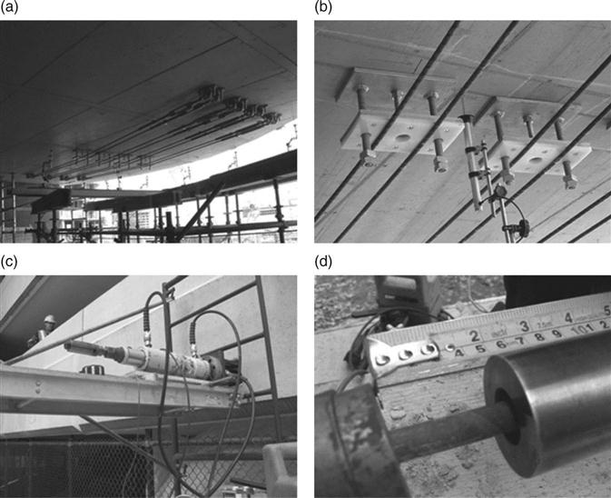
Field applications of prestressed FRP composites have been increasingly accepted by the civil engineering community around the world. Prestressed FRP composites have been used to construct new bridges and to repair existing bridges (Basler and Clenin, 2004; Grace et al., 2004; Kim et al., 2006; ISIS, 2009). FRP composites provide a unique feature in that fiber optic sensors can be incorporated with FRPs to monitor the real time performance of bridges (Rizkalla and Tadros, 1994). Some pictures of field applications are shown in Fig. 2.1. Further examples are available elsewhere (ACI, 2007; ISIS, 2009). The following sections provide a comprehensive overview of various applications of prestressed FRP composites from a practical perspective, such as prestressing operation and flexural responses of concrete members with prestressed FRP composites.
2.4 Internally bonded FRP tendons
The use of internally bonded FRP tendons is the most common method for FRP-prestressed concrete beams, as shown in Fig. 2.2a and Table 2.2. FRP-prestressed beams are designed in such a way that concrete sections are not cracked in service load (Grace and Singh, 2003), which is an analogous design approach to steel-prestressed beams. In some cases, unstressed FRP tendons are added to an FRP-prestressed beam to provide additional load-carrying capacity and ductility of the beam (Saafi and Toutanji, 1998; Grace and Singh, 2003). Conventional section analysis (i.e., strain compatibility) may be used for the application of internally bonded FRP tendons.

Table 2.2
Flexural behavior of selected prestressed FRP composites for concrete structures
| Reference | Test specimen | Prestressed FRP | Reinforcement | Material propertya | Flexural behaviorb | ||||||||||
| ID | Size (ft)* | Fiber | Type | ρF (%)† | Typec | f′c (MPa) | fpu (MPa) | εpu (%) | Ep (GPa) | Pressure level (%)‡ | Pcr (kN) | Pu (kN) | Pcr/Pu (%) | Failure mode | |
| Nanni and Tanigaki (1992) | A2 | 13.1 | AFRP | Tendon | 0.33 | IB | 37 | 1640 | 2.2 | 76 | 23 | 6§ | 12§ | 50.0 | Slip |
| B1 | 13.1 | AFRP | Tendon | 0.36 | IB | 38 | 1460 | 2.1 | 68 | 24 | 6§ | 13§ | 46.2 | Crushing | |
| B2 | 13.1 | AFRP | Tendon | 0.71 | IB | 39 | 1460 | 2.1 | 68 | 24 | 9§ | 23§ | 39.1 | Crushing | |
| C1 | 13.1 | AFRP | Tendon | 0.71 | IB | 34 | 1390 | 2.2 | 63 | 53 | 12§ | 27§ | 44.4 | Slip | |
| D1 | 13.1 | AFRP | Tendon | 0.36 | IB | 39 | 1460 | 2.1 | 68 | 48 | 9§ | 15§ | 60.0 | Crushing | |
| McKay and Erki (1993) | B1 | 6.9 | AFRP | Tendon | 0.13 | IB | 41 | 2500 | 3.7 | 53 | 45 | 17§ | 35§ | 48.6 | Rupture |
| B2 | 6.9 | AFRP | Tendon | 0.13 | IB | 40 | 2500 | 3.7 | 53 | 46 | 17§ | 33§ | 51.5 | Rupture | |
| B3 | 6.9 | AFRP | Tendon | 0.13 | IB | 40 | 2500 | 3.7 | 53 | 46 | 18§ | 40§ | 45.0 | Rupture | |
| Taerwe and Matthys (1995) | 1 | 10.5 | AFRP | Tendon | 0.60 | IB | 69 | 3000 | 3.0 | 91 | 55 | 7 | 19 | ZI.2 | Crushing |
| 2 | 10.5 | AFRP | Tendon | 0.60 | IB | 69 | 3000 | 3.0 | 91 | 55 | 8 | N/A | N/A | N/A | |
| 3 | 10.5 | AFRP | Tendon | 0.60 | IB | 65 | 3000 | 3.0 | 91 | 55 | 9 | 18 | 50.0 | Crushing | |
| 4 | 10.5 | AFRP | Tendon | 0.60 | IB | 99 | 3000 | 3.0 | 91 | 55 | 9 | 21 | 42.6 | Rupture | |
| 7 | 10.5 | AFRP | Tendon | 0.60 | IB | 69 | 3000 | 3.0 | 91 | 55 | 8 | 23 | 34.6 | Crushing | |
| 8 | 10.5 | AFRP | Tendon | 0.60 | IB | 69 | 3000 | 3.0 | 91 | 55 | 8 | 28 | 28.6 | Crushing | |
| Gowripalan et al. (1996) | Arpr40 | 10.5 | AFRP | Tendon | 0.44 | IB | 35 | 1300 | 2.3 | 56 | 31 | 20§ | 50§ | 40.0 | Crushing |
| Arpr80 | 10.5 | AFRP | Tendon | 0.44 | IB | 85 | 1300 | 2.3 | 56 | 35 | 25§ | 50§ | 50.0 | Rupture | |
| Niitani et al. (1997) | BA-1M | 39.4 | AFRP | Tendon | 1.3 | IB | 58 | 1250 | 2.0 | 64 | 45 | 55 | 131 | 42.3 | Crushing |
| BA-6Y | 39.4 | AFRP | Tendon | 1.3 | IB | 58 | 1250 | 2.0 | 64 | 45 | 54 | 129 | 41.9 | Crushing | |
| Saafi and Toutanji (1998) | B1 | 8.2 | AFRP | Tendon | 0.32 | IB | 45 | 1330 | 2.1 | 50 | 50 | 36 | 51 | 71.1 | Rupture |
| B2 | 8.2 | AFRP | Tendon | 0.32 | IUB | 45 | 1330 | 2.1 | 50 | 50 | 31 | 44 | 70.7 | Rupture | |
| B3 | 8.2 | AFRP | Tendon | 0.32 | IB&IUB | 45 | 1330 | 2.1 | 50 | 50 | 39 | 43 | 91.7 | Rupture | |
| B4 | 8.2 | AFRP | Tendon | 0.48 | IUB | 45 | 1330 | 2.1 | 50 | 50 | 32 | 49 | 65.5 | Rupture | |
| Toutanji and Saafi (1999) | C1 | 16.4 | AFRP | Tendon | 0.48 | IB | 45 | 1330 | 2.1 | 50 | 50 | 85 | 195 | 43.7 | Rupture |
| C2 | 16.4 | AFRP | Tendon | 0.68 | IUB | 45 | 1330 | 2.1 | 50 | 50 | 85 | 185 | 46.1 | Rupture | |
| C3 | 16.4 | AFRP | Tendon | 0.48 | IB&IUB | 45 | 1330 | 2.1 | 50 | 50 | 86 | 155 | 55.6 | Rupture | |
| C4 | 16.4 | AFRP | Tendon | 0.48 | IUB | 45 | 1330 | 2.1 | 50 | 50 | 85 | 143 | 59.7 | Rupture | |
| Lees and Burgoyne (1999) | TB(1) | 9.2 | AFRP | Tendon | 0.13 | IB | 59 | 1800 | 3.3 | 54 | 68 | N/A | 8 | N/A | Rupture |
| TB(2) | 9.2 | AFRP | Tendon | 0.13 | IB | 59 | 1800 | 3.3 | 54 | 68 | N/A | 8 | N/A | Rupture | |
| FB | 9.2 | AFRP | Tendon | 0.17 | IB | 69 | 1430 | 2.1 | 69 | 59 | N/A | 8 | N/A | Rupture | |
| TUB | 9.2 | AFRP | Tendon | 0.17 | IUB | 60 | 1800 | 3.3 | 54 | 63 | N/A | 6 | N/A | Crushing | |
| FUB | 9.2 | AFRP | Tendon | 0.17 | IUB | 60 | 1430 | 2.1 | 69 | 63 | N/A | 6 | N/A | Crushing | |
| TIB1 | 9.2 | AFRP | Tendon | 0.13 | IPB | 56 | 1800 | 3.3 | 54 | 65 | N/A | 7 | N/A | Crushing | |
| TIB2 | 9.2 | AFRP | Tendon | 0.13 | IPB | 56 | 1800 | 3.3 | 54 | 65 | N/A | 8 | N/A | Crushing +Rupture | |
| FIB1 | 9.2 | AFRP | Tendon | 0.17 | IPB | 56 | 1430 | 2.1 | 69 | 62 | N/A | 7 | N/A | Crushing | |
| FIB2 | 9.2 | AFRP | Tendon | 0.17 | IPB | 56 | 1430 | 2.1 | 69 | 65 | N/A | 7 | N/A | Rupture | |
| TAB | 9.2 | AFRP | Tendon | 0.13 | IB | 58 | 1800 | 3.3 | 54 | 65 | N/A | 6 | N/A | Crushing | |
| FAB | 9.2 | AFRP | Tendon | 0.17 | IB | 58 | 1430 | 2.1 | 69 | 64 | N/A | 8 | N/A | Crushing +Rupture | |
| Stoll et al. (2000) | Beam2 | 40.0 | CFRP | Tendon | 0.24 | IB | 71 | 2600 | 1.6 | 147 | 77 | 182 | 569 | 32.1 | Rupture |
| Dolan and Swanson (2002) | C1-H | 32.8 | CFRP | Tendon | 0.12 | IB | 43 | 1820 | 1.2 | 146 | 60 | N/A | 166§ | N/A | Rupture |
| C2-H | 32.8 | CFRP | Tendon | 0.12 | IB | 43 | 1820 | 1.2 | 146 | 60 | N/A | 158§ | N/A | Rupture | |
| Elrefai et al. (2007) | OL-DD | 11.5 | CFRP | Tendon | 0.37 | EUB | 35 | 2160 | 1.5 | 144 | 40 | 30 | 110 | 27.2 | Crushing |
| Nordin and Taljsten (2006) | BPS1 | 13.1 | CFRP | Rod | 0.17 | NSM | 68 | 2800 | 1.8 | 160 | 10 | 20 | 121 | 16.6 | Rupture |
| BPS2 | 13.1 | CFRP | Rod | 0.17 | NSM | 68 | 2800 | 1.8 | 160 | 10 | 21 | 121 | 17.3 | Rupture | |
| BPS3 | 13.1 | CFRP | Rod | 0.17 | NSM | 66 | 2800 | 1.8 | 160 | 12 | 23 | 120 | 19.0 | Rupture | |
| BPS4 | 13.1 | CFRP | Rod | 0.17 | NSM | 64 | 2800 | 1.8 | 160 | 12 | 23 | 123 | 18.5 | Rupture | |
| BPS5 | 13.1 | CFRP | Rod | 0.17 | NSM | 67 | 2800 | 1.8 | 160 | 20 | 26 | 122 | 21.2 | Rupture | |
| BPS6 | 13.1 | CFRP | Rod | 0.17 | NSM | 67 | 2800 | 1.8 | 160 | 20 | N/A | 148 | N/A | Rupture | |
| BPM1 | 13.1 | CFRP | Rod | 0.17 | NSM | 63 | 2000 | 0.8 | 250 | 16 | 25 | 128 | 19.5 | Rupture | |
| BPM2 | 13.1 | CFRP | Rod | 0.17 | NSM | 62 | 2000 | 0.8 | 250 | 16 | 25 | 132 | 18.9 | Rupture | |
| BPM3 | 13.1 | CFRP | Rod | 0.17 | NSM | 65 | 2000 | 0.8 | 250 | 27 | 32 | 131 | 24.2 | Rupture | |
| BPM4 | 13.1 | CFRP | Rod | 0.17 | NSM | 66 | 2000 | 0.8 | 250 | 19 | 23 | 123 | 18.5 | Rupture | |
| Wu et al. (2007) | 3 | 6.9 | CFRP | Tendon | 0.29 | NSM | 46 | 2100 | 2.2 | 95 | 15 | 23 | 137 | 16.6 | Debond |
| 4 | 6.9 | CFRP | Tendon | 0.29 | NSM | 46 | 2100 | 2.2 | 95 | 30 | 30 | 147 | 20.4 | Debond | |
| 5 | 6.9 | CFRP | Tendon | 0.29 | NSM | 46 | 2100 | 2.2 | 95 | 30 | 32 | 148 | 21.4 | Crushing | |
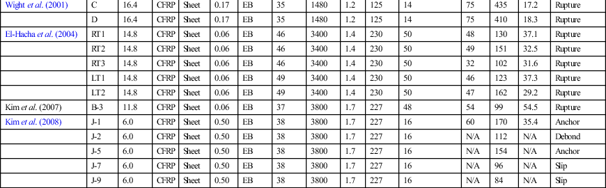
| Wight et al. (2001) | C | 16.4 | CFRP | Sheet | 0.17 | EB | 35 | 1480 | 1.2 | 125 | 14 | 75 | 435 | 17.2 | Rupture |
| D | 16.4 | CFRP | Sheet | 0.17 | EB | 35 | 1480 | 1.2 | 125 | 14 | 75 | 410 | 18.3 | Rupture | |
| El-Hacha et al. (2004) | RT1 | 14.8 | CFRP | Sheet | 0.06 | EB | 46 | 3400 | 1.4 | 230 | 50 | 48 | 130 | 37.1 | Rupture |
| RT2 | 14.8 | CFRP | Sheet | 0.06 | EB | 46 | 3400 | 1.4 | 230 | 50 | 49 | 151 | 32.5 | Rupture | |
| RT3 | 14.8 | CFRP | Sheet | 0.06 | EB | 46 | 3400 | 1.4 | 230 | 50 | 32 | 102 | 31.6 | Rupture | |
| LT1 | 14.8 | CFRP | Sheet | 0.06 | EB | 49 | 3400 | 1.4 | 230 | 50 | 46 | 123 | 37.3 | Rupture | |
| LT2 | 14.8 | CFRP | Sheet | 0.06 | EB | 49 | 3400 | 1.4 | 230 | 50 | 47 | 162 | 29.2 | Rupture | |
| Kim et al. (2007) | B-3 | 11.8 | CFRP | Sheet | 0.06 | EB | 37 | 3800 | 1.7 | 227 | 48 | 54 | 99 | 54.5 | Rupture |
| Kim et al. (2008) | J-1 | 6.0 | CFRP | Sheet | 0.50 | EB | 38 | 3800 | 1.7 | 227 | 16 | 60 | 170 | 35.4 | Anchor |
| J-2 | 6.0 | CFRP | Sheet | 0.50 | EB | 38 | 3800 | 1.7 | 227 | 16 | N/A | 112 | N/A | Debond | |
| J-5 | 6.0 | CFRP | Sheet | 0.50 | EB | 38 | 3800 | 1.7 | 227 | 16 | N/A | 154 | N/A | Anchor | |
| J-7 | 6.0 | CFRP | Sheet | 0.50 | EB | 38 | 3800 | 1.7 | 227 | 16 | N/A | 96 | N/A | Slip | |
| J-9 | 6.0 | CFRP | Sheet | 0.50 | EB | 38 | 3800 | 1.7 | 227 | 16 | N/A | 84 | N/A | Slip | |
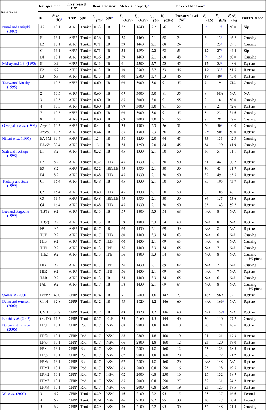
*Length of test specimen.
†ρF = Afrp/Aconcrete.
‡Percentage of prestress level with respect to ultimate property.
§Moment capacity (kNm).
af′c = concrete strength, fpu = ultimate FRP strength, Ep = FRP tensile modulus, εpu = FRP rupture strain.
bPcr = cracking loads, Pu = ultimate loads.
cIB = internally bonded, IUB = internally unbonded, EB = externally bonded, EUB = externally unbonded, NSM = near-surface mounted.
2.4.1 Prestressing operation
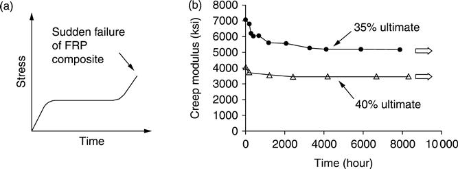
A prestressing operation may be conducted using hydraulic jacks reacting against anchorage. Special attention should be paid to gripping methods for FRP tendons during a jacking operation, to avoid premature failure of the tendons near the FRP-anchorage junction where stress concentrations occur. The reason is attributed to the relatively weak strength of FRP tendons in the radial direction (i.e., longitudinal strength of an FRP tendon is approximately ten times greater than radial strength). Various types of anchor systems have been developed to effectively prestress FRP tendons (Fig. 2.3), for example, clamp type (Malvar and Bish, 1995), plug-and-cone type (Burgoyne, 1988; Nanni et al., 1996; Sayed-Ahmed and Shrive, 1998), and bond type (Zhang and Benmokrane, 2002) anchors. Further details of anchorage are available elsewhere (ACI, 2004). Typical prestressing levels are 50–65% of the ultimate strength for AFRP and CFRP tendons, respectively (ACI, 2004). The reason is owing to the stress-rupture of FRP tendons, which may result in abrupt failure of FRP-prestressed concrete members subjected to long-term load. A stress-rupture phenomenon is illustrated in Fig. 2.4a. The long-term behavior of FRP composites depends on the level of prestress, as shown in Fig. 2.4b. Synergies from various factors may accelerate stress-rupture, including alkaline environment and temperature (Budelmann and Rostasy, 1993). An increase in the initial prestress level of FRP tendons increases transfer length in the concrete (Nanni and Tanigaki, 1992). Numerical comparisons of various predictive models on the transfer length of FRP tendons are to be discussed in Section 2.9.1. Allowable stresses in concrete and FRP tendons at transfer of the prestress and under service conditions are summarized in ACI-440.4R-04 (ACI, 2004).
2.4.2 Flexural behavior
The behavior of an internally bonded FRP-prestressed concrete beam depends on a reinforcement ratio that is categorized into three groups (Burke and Dolan, 2001): over-reinforced (ρ > ρb; where ρ is the reinforcement ratio and ρb is the balanced reinforcement ratio), under-reinforced (ρ < ρb), and significantly under-reinforced (ρ < 0.5ρb) sections. The balanced reinforcement ratio of ρb is defined as the reinforcement ratio at which concrete crushes and FRP ruptures simultaneously. As shown in Table 2.2, reinforcement ratios of prestressed FRP members are well below those of conventional reinforced concrete members having 1–1.5%.
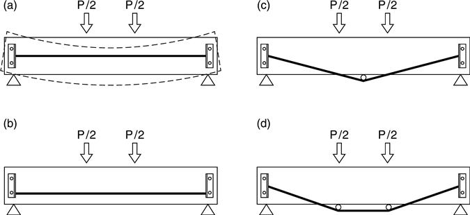
FRP-prestressed beams show almost identical behavior to steel-prestressed beams prior to cracking (Sen et al., 1993; Abdelrahman and Rizkalla, 1995) because the response of prestressed concrete beams until cracking is mainly governed by concrete sections, rather than reinforcement. To prevent sudden flexural failure immediately after the cracking of a beam, minimum reinforcement should be placed (ACI, 2004). Post-cracking deflections and crack widths of FRP-prestressed beams are greater than those of steel-prestressed beams, as shown in Fig. 2.5, because of the low modulus of FRP tendons (i.e., 62–150 GPa for FRPs, while 200 GPa for typical steel strands) (Sen et al., 1993; Dolan et al., 2000; Dolan and Swanson, 2002; ACI, 2004). Post-cracking deflection is also influenced by a reinforcement ratio (Grace and Singh, 2003). An increase of stresses in FRP tendons is observed at the locations of flexural cracks along the beam span (Nanni and Tanigaki, 1992) due to a lack of stress-sharing between the concrete and FRP tendon at cracked locations. An increase of stress levels in bonded FRP tendons is significant when compared to that of unbonded FRP tendons (Sections 2.5 and 2.6) (Pisani, 1998). This is related to the strain compatibility of the section. FRP-prestressed beams demonstrate higher stiffness than steel-prestressed beams after yielding of the steel, as shown in Fig. 2.5a.
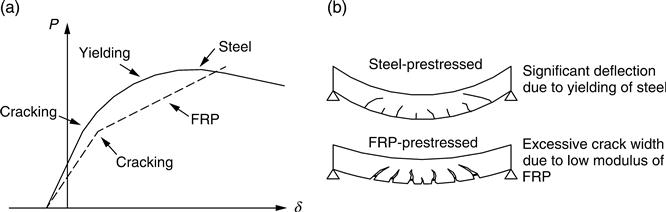
For under-reinforced beams, rupture of FRP tendons controls the failure of the beams, rather than concrete crushing. A progressive rupture failure may occur in a concrete beam prestressed with vertically-distributed FRP tendons (Dolan and Swanson, 2002). This failure characteristic of FRP tendons is different from that of steel strands, which exhibit a yield plateau. The FRP tendon located furthest from the extreme compression fiber of a concrete section, thus, governs the strain capacity of the beam, so that a sudden decrease in load-carrying capacity may take place when the governing tendon ruptures. In lieu of showing a yield load (Fig. 2.5a), FRP-prestressed beams exhibit significant crack width (e.g., about 5 mm at ultimate) as an indicator of imminent failure, as shown in Fig. 2.5b. FRP-prestressed beams may absorb less energy than steel-prestressed beams due to the absence of yield characteristics (Zou, 2003). For over-reinforced beams, concrete crushing is the primary contribution to the failure of the beams (Nanni and Tanigaki, 1992). Such a compression-controlled failure mode may be recommended for the design of FRP-prestressed concrete beams, considering safety issues (Lees, 2001; Grace and Singh, 2003). A ratio between cracking and ultimate loads (i.e., Pcr/Pu) was influenced by the level of prestress, as shown in Table 2.2; in other words, the Pcr/Pu ratio increased when a prestress level increased.
Sustained load levels significantly influence the deflection of an FRP-prestressed beam. For example, a difference between long-term (288 days) and short-term deflections was up to 540% under a sustained load equivalent to the cracking load (Zou, 2003). The low modulus of FRP tendons causes lower long-term prestress losses than those of steel strands; however, such a characteristic may cause a significant increase in camber of the prestressed member (Youakim and Karbhari, 2007). The creep response of FRP-prestressed members was greater than that of steel-prestressed cases (Soudki et al., 1997). The coefficients for predicting time-dependent behavior of steel-prestressed concrete beams may thus not be applicable to FRP-prestressed beams. Correspondingly, ACI 440.4R-04 (ACI, 2004) suggests long-term coefficients to estimate the deflection of concrete members with FRP tendons.
2.5 Internally unbonded FRP tendons
FRP tendons may be unbonded from concrete by using plastic ducts or sheaths, as shown in Fig. 2.2b. This type of prestressing provides global deformation compatibility, rather than section compatibility (Rao and Mathew, 1996; Naaman et al., 2002), taking into account the slippage between concrete and FRP tendons. For designing such a prestressing application, a strain reduction factor may be used (Naaman and Alkhairi, 1991). Part of the concept of the strain reduction factor is that strains in a tendon are calculated using a conventional sectional-analysis (i.e., fully-bonded tendons), and then the calculated strains are multiplied by a reduction factor to account for the reduced strain effect of the unbonded FRP tendons. The reduction factor varies depending upon the level of cracking of a beam and load configurations (ACI, 2004). When a prestressed member is loaded in flexure, an increase of stresses in unbonded FRP tendons is not significant compared to that of fully-bonded FRP tendons. For design purposes, the ultimate stress in an unbonded FRP tendon is conveniently expressed as (ACI, 2004)
[2.1]
where fp is the ultimate stress in the FRP tendon, fpe is the effective prestress prior to applying live load, and Δfp is the stress increase due to live load.
2.5.1 Prestressing operation
Post-tensioning is performed to prestress a concrete beam with internally unbonded FRP tendons. Sheaths for prestressing are placed inside the beam and the concrete is cast. After adequate hardening of the concrete (i.e., usually 7–10 days after casting), FRP tendons located inside a sheath are post-tensioned using hydraulic jacks and permanently anchored at the ends of the beam. Contrary to steel strand applications, the sheaths may not be grouted because FRP tendons are non-corrosive. Allowable prestressing requirements are available in ACI440.4R-04 (ACI, 2004).
2.5.2 Flexural behavior
A concrete beam with internally unbonded FRP tendons exhibits greater deflections, fewer flexural cracks, and lower ultimate loads than a beam with fully-bonded FRP tendons, as shown in Fig. 2.6 (Saafi and Toutanji, 1998; Lees and Burgoyne, 1999; Toutanji and Saafi, 1999). Possible reasons for such a relatively low load-carrying capacity are attributed to the slippage of unbonded FRP tendons and strain localization at cracked locations. The localized cracks of a concrete beam with unbonded FRP tendons (Fig. 2.6b) are due to a lack of horizontal shear stress interaction between the concrete and unbonded FRP tendons along the beam span. The mode of failure was not affected by concrete strength, whereas it was substantially influenced by the method of prestressing (e.g., unbonded or bonded), as shown in Table 2.2.

2.6 Externally unbonded FRP tendons
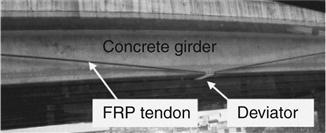
Prestressed FRP tendons may be located outside a concrete beam to provide tensile resistance. Externally unbonded FRP tendons may particularly be suitable for strengthening existing concrete beams to increase insufficient load-carrying capacity. Figure 2.7 shows a bridge girder strengthened with an unbonded FRP tendon. Benefits of such an externally unbonded FRP tendon application include an insignificant increase in dead load and rapid inspections, followed by an easy replacement of damaged (if any) FRP tendons (ACI, 2004). For analytical prediction of the behavior of a beam with externally unbonded FRP tendons, global displacement compatibility should be accounted for, rather than section compatibility. For practical design and site applications of externally unbonded FRP tendons, attention should be paid to a prestress level and the number of deviators (to be discussed).
2.6.1 Prestressing operation
An anchor system is required at the ends of a target beam to post-tension FRP tendons, as shown in Fig. 2.8. Post-tensioning is conducted after adequate aging of the concrete, thus a possibility of the failure of bearing concrete at the anchorage region may be lower. During post-tensioning, care must be exercised to provide safety to site workers because the stressed FRP tendons can rupture prior to reaching a target prestress level. It is thus suggested that safety brackets be placed along the beam span during prestressing FRP tendons. In the case of post-tensioning multiple FRP tendons, a gradual increase in prestressing force may be recommended to preserve the lateral stability of the concrete beam. Transfer of prestress to the concrete should be gradual. Unbonded FRP tendons experience constant stresses in the longitudinal direction except at the locations of deviators and anchorage where stress concentrations occur.
2.6.2 Flexural behavior
The behavior of a concrete beam prestressed with externally unbonded FRP tendons is different from that with internally bonded or unbonded FRP tendons, because of a change in the effective depth of FRP tendons induced by bending of the beam (Ghallab and Beeby, 2005) as schematically shown in Fig. 2.8a. The change of beam-eccentricity may provide less structural efficiency because it reduces a moment-arm between compression and tension forces. The contribution of FRP tendons to the flexural strength of a beam decreases accordingly. A depth reduction factor in the strength prediction of such a beam is proposed to take into account variable tendon eccentricity (Aravinthan and Mutsuyoshi, 1997). Variation of the effective depth of a beam strengthened with externally unbonded FRP tendons may be controlled by deviators that provide a constant tendon eccentricity especially within a high moment zone (Fig. 2.8c and 2.8d). Stress concentrations of FRP tendons at deviators should be taken into consideration for such strengthening applications. A cushioning material may be placed at the interface between FRP tendons and deviators (Grace, 1999). The slippage of FRP tendons at deviation points (Rao and Mathew, 1996) may induce the abrasion of FRP tendons, which can accelerate stress concentrations. An increase in the number of deviators (Fig. 2.8c and 2.8d) increases the load-carrying capacity of a concrete beam prestressed with externally unbonded FRP tendons (Rao and Mathew, 1996; Ghallab and Beeby, 2005) as well as stresses in the deviated tendons (Ghallab and Beeby, 2005). Typical cracking patterns of a beam with externally unbonded FRP tendons are analogous to those of a beam with internally unbonded FRP tendons (i.e., a few localized cracks, Fig. 2.6b). When the beam is loaded in flexure an increase in stress levels of externally unbonded FRP tendons is insignificant in comparison to that of bonded FRP tendons (Pisani, 1998). This is related to a strain compatibility effect in the section. Equation [2.1] may, thus, be used for externally unbonded FRP applications. Prestressed beams using externally unbonded FRP tendons, in general, fail due to concrete crushing, rather than FRP rupture under monotonic flexural load (Grace and Abdel-Sayed, 2000; Ghallab and Beeby, 2005). Although the long-term performance of a concrete beam with externally unbonded FRP tendons is an important issue because of the stress concentrations and damage propagation of the tendons, limited research has been reported. Experimental investigations are, therefore, recommended to examine local damage propagation under various load configurations, including fatigue load.
2.7 Externally bonded post-tensioned FRP laminate
In order to strengthen or repair an existing concrete member in flexure, externally bonded post-tensioned FRP laminates may be used (Meier, 1995; Wight et al., 2001; El-Hacha et al., 2004; Kim et al., 2008a,b,c,d). CFRP laminates are recommended for this application because of their favorable time-dependent behavior and high strength and stiffness compared to AFRP or GFRP composites (Meier, 1995). For such an innovative strengthening method, FRP laminates are tensioned (prior to bonding on the surface of the concrete) and then permanently bonded to the tensile side of the target structure using an epoxy adhesive, as shown in Fig. 2.2c. Notable benefits of the concrete members strengthened with prestressed FRP laminates are an active load-carrying mechanism (i.e., prestressed FRP laminates can sustain not only live load but also dead load), restored prestress losses in a prestressed concrete member, improved serviceability, and stress redistribution of existing concrete structures (Triantafillou et al., 1992; Wight et al., 2001; Kim et al., 2007a). The most critical concerns of prestressed FRP-sheet application are prestressing methods and premature delamination failure. An adequate anchor system may prevent the premature delamination failure of the prestressed FRP laminates (Wight et al., 2001; Kim et al., 2005, 2008b).
2.7.1 Prestressing operation
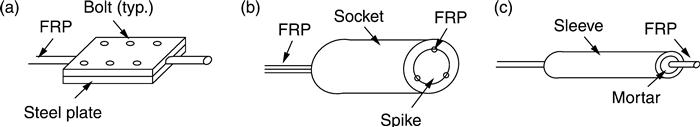
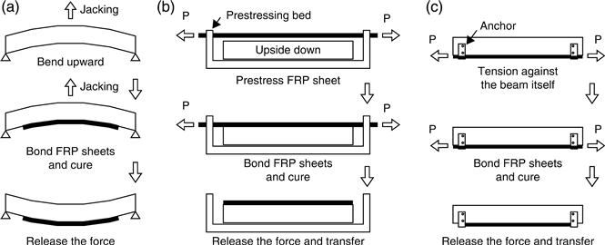
A typical prestress level of 15%–50% of the ultimate tensile capacity has been applied to FRP laminates (Wight et al., 2001; El-Hacha et al., 2004; Kim et al., 2007a). Recent research recommends that a level of prestress in CFRP laminates be 20% of the ultimate design strength, taking into account an adequate strength increase and ductility of strengthened members (Kim et al., 2010). Three different methods are available for prestressing FRP laminates (Wight et al., 2001). A schematic summary is given in Fig. 2.9. The first method (Fig. 2.9a) includes the artificial camber of a concrete beam (Saadatmanesh and Ehsani, 1991). The target beam is first loaded upward using a hydraulic jack and then FRP laminates are bonded to the bottom of the beam. After curing of the FRP laminates, the jack is removed so that a prestress is naturally applied to the sheets by gravity. This method, however, provides a very low level of prestress to the FRP laminates (e.g., less than 3% of the ultimate strength of FRP (Saadatmanesh and Ehsani, 1991)). The second method (Fig. 2.9b) uses an external prestressing apparatus (Triantafillou et al., 1992; Meier, 1995). FRP laminates are prestressed in an independent prestressing frame and bonded to the soffit of a target beam. The external frame is then removed after curing of the strengthening system. This method is suitable for laboratory investigations; however, it may not be practical for site application because of the need for a prestressing frame. The third method (Fig. 2.9c) is called the direct-tensioning method (Wight et al., 2001; El-Hacha et al., 2004; Kim et al., 2005, 2007, 2008a,d). An anchor system is mounted in a beam and FRP laminates are directly tensioned against the beam itself (Kim et al., 2009). Steel anchors are commonly used to sustain a high level of prestressing force. The most notable advantage of this prestressing method is its applicability on site (i.e., no prestressing frames are necessary for a prestressing operation, Fig. 2.9b and 2.9c). A field application has been recently conducted using the direct-tensioning method to repair an impact-damaged prestressed concrete girder bridge (Kim et al., 2006). Steel anchorage used for prestressing FRP laminates may be left permanently (Wight et al., 2001; El-Hacha et al., 2004; Kim et al., 2007, 2008a) or may be removed after curing of the post-tensioned FRP laminates (Kim et al., 2008b).
2.7.2 Flexural behavior
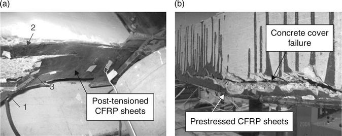
Externally bonded prestressed FRP laminates may significantly enhance the serviceability of existing concrete beams. A strengthened beam with prestressed FRP laminates exhibits a remarkably higher cracking load with improved stiffness when compared to a beam strengthened with unprestressed FRP laminates (Triantafillou et al., 1992; Wight et al., 2001; El-Hacha et al., 2004; Kim et al., 2008a). The beams strengthened with prestressed FRP laminates show many cracks of small width, whereas unstrengthened control beams show a few large cracks (Wight et al., 2001; El-Hacha et al., 2004).This observation implies that prestressed FRP laminates can effectively distribute applied stresses along the strengthened beam (i.e., reduced stress localization). Prestressed FRP laminates may close existing cracks (Kim et al., 2008a), which is a benefit in terms of durability (i.e., reduced possibility of moisture ingress into the concrete beam). The level of stress in existing internal reinforcement subjected to external load is reduced after strengthening because of a stress redistribution mechanism that may result in an increased yield load capacity of a strengthened beam (Wight et al., 2001; Kim et al., 2005). Failure of a strengthening system is attributed to either rupture of post-tensioned FRP laminates (Wight et al., 2001; El-Hacha et al., 2004; Kim et al., 2007a) or shear-off of FRP laminates (Triantafillou et al., 1992; Kim et al., 2008b), as shown in Fig. 2.10. Progressive rupture of prestressed FRP laminates may be observed (Kim et al., 2007a) because of uneven prestressing forces across the FRP laminates (Fig. 2.10a). These uneven prestressing forces are mainly attributed to three reasons, namely, misaligned FRP laminates at anchorage when the laminates are post-tensioned, deformation of the anchorage under a high level of prestress, and uneven jacking forces during a prestressing operation. Care should thus be exercised, when a prestress is applied to FRP laminates, to avoid uneven stress distribution across the laminates, which may result in localized failure of the laminates (Fig. 2.10a). The shear-off failure of FRP laminates may be associated with a number of shear-off cracks at the level of concrete cover (Fig. 2.10b) because prestressed FRP laminates tend to return to their unstressed state when the strengthened beam is loaded in flexure.
2.8 Near-surface-mounted post-tensioned FRP bars
The NSM strengthening method is a relatively new technology for strengthening concrete beams. This method includes cutting narrow grooves along the tension side of a target beam, and inserting FRP bars or strips into the slits, then bonding them using an adhesive (fib, 2001), as shown in Fig. 2.2d. To improve strengthening effects, NSM FRP composites may be prestressed. Advantages of such prestressed NSM FRP application include enhanced force transfer from FRP to concrete, improved durability, and increased impact resistance (Nordin and Taljsten, 2006). Limited investigations of prestressed NSM FRPs have been reported previously (Nordin and Taljsten, 2006; Taljsten and Nordin, 2007; Wu et al., 2007).
2.8.1 Prestressing operation
A prestressing operation for NSM FRP bars is typically conducted using an external apparatus (Nordin and Taljsten, 2006; Wu et al., 2007). Contrary to the application of prestressed FRP laminates mentioned in a previous section, no additional anchorage may be required to prevent premature bond failure of the FRP composites. The reason is that prestressed NSM reinforcement is located inside a strengthened beam (Fig. 2.2d) and thus better bond is achieved as compared to externally bonded FRP laminates (Fig. 2.2c). Practical prestressing methods for NSM FRP bars should be developed for site application.
2.8.2 Flexural behavior
The flexural behavior of a concrete beam strengthened with prestressed NSM FRP bars is analogous to that of a beam with prestressed FRP laminates. Although post-cracking stiffness of beams with prestressed and non-prestressed NSM bars is similar, the cracking load of the beam with prestressed NSM bars is higher than that of the non-prestressed case due to a prestressing effect (Nordin and Taljsten, 2006). Yield capacity of beams strengthened with prestressed NSM FRP bars is significantly improved when compared to that of an unstrengthened control beam. Ductility of the strengthened beams, however, decreases when a prestressing level increases (Nordin and Taljsten, 2006). A similar observation was made in the case of beams strengthened with prestressed CFRP laminates (Kim et al., 2010). Yield load of a strengthened beam is influenced by the level of prestress in NSM bars and corresponding tensile modulus. The failure of beams strengthened with prestressed NSM FRP bars is, in general, governed by fiber failure in NSM bars, rather than premature debonding or slip failure of the bars (Nordin and Taljsten, 2006). More testing is necessary for this type of strengthening technique.
2.9 Bond characteristics and deformability
Bond and deformability are crucial parameters to consider for FRP application. Inadequate bond significantly influences the performance of an FRP system. Sufficient deformability is necessary to ensure the safety of FRP structures. This section discusses the significance of these two subjects, including their practical considerations.
2.9.1 Bond characteristics
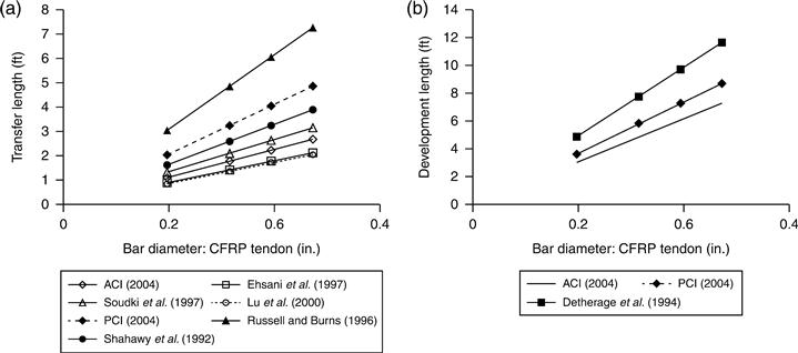
The surface of FRP tendons varies depending upon manufacturers. Surface conditions may affect the bond quality of FRP tendons embedded in concrete. FRP tendons (Table 2.1) are usually treated to have a rough surface – for instance, sand-coated (Arapree), fiber-wrapped (CFCC), and indented (Leadline) tendons. Bond resistance of FRP tendons is substantiated by friction and mechanical interlock (Zhang and Benmokrane, 2002). Bond characteristics of FRP tendons for concrete members may thus be different from those of steel strands. ACI 440.4R-04 (ACI, 2004) reports empirical equations to estimate adequate development and transfer lengths for prestressed FRP tendons. Figure 2.11 compares various existing models to predict the bond characteristics of FRP tendons. It should be noted that the models with solids dots in Fig. 2.11 were originally developed for seven-wire steel tendons. The material properties assumed for the numerical comparison were an ultimate strength of CFRP (fpu) of 2450 MPa, effective and initial prestressing levels of 0.6 fpu and 0.8 fpu, respectively, and a concrete strength of 40 MPa. The predictive models based on steel strands were relatively conservative when compared to those based on FRP tendons. This is possibly due to the rough surface of FRP tendons; in other words, seven-wire steel strands do not have rough surface. Bond failure of FRP tendons causes a significant loss in load-carrying capacity of the beam prestressed with internally bonded FRP tendons. The evidence of such a beam failure mode is observed by excessive longitudinal cracks at the level of prestressed FRP tendons (Zou, 2003). Although such a bond failure mode is not an issue for unbonded FRP tendon application, bond of FRP tendons at anchorage should still be accounted for to avoid local failure.
For strengthening concrete members, bond is a critical consideration for the application of post-tensioned FRP laminates, taking into account their premature delamination failure. An adequate anchor system precludes the premature bond failure of prestressed FRP laminates bonded to the soffit of a concrete member (Wight et al., 2001; El-Hacha et al., 2004; Kim et al., 2008a,d). Typical bond failure of prestressed FRP laminates due to a lack of adequate anchorage is available in Triantafillou et al. (1992). A bond critical zone near the cut-off points of prestressed FRP laminates may reasonably be assumed to be the shear stress concentration region where excessive horizontal shear deformation of the matrix resin (used to bond FRP laminates to the concrete) occurs (Kim et al., 2008c). Prediction of a shear concentration region is available in literature (Taljsten 1997; Smith and Teng, 2001). Prestressed NSM FRP bars provide better bond resistance than externally bonded prestressed FRP laminates. This is due to the fact that more areas of FRP composites are interacted with concrete (i.e., prestressed NSM bars are located inside the concrete beam). Flexural testing indicates that no bond failure of prestressed NSM FRP bars has been observed until failure of test beams takes place (Nordin and Taljsten, 2006).
2.9.2 Deformability
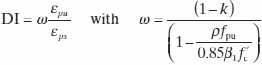
Conventional ductility concepts (i.e., a ratio between the yield and ultimate response of a concrete beam under flexural load) are not applicable to a beam with FRPs, because FRP composites do not exhibit yield characteristics. Deformability is an alternative to quantify the flexural behavior of a concrete beam with FRP composites. For a beam prestressed with FRP composites, deformability may be defined as the ability to resist applied load after cracking of a beam section without a significant loss of load-carrying capacity. For a design purpose, deformability indices are proposed by CHBDC (2006) and ACI 440.4R-04 (ACI, 2004) as shown in Equations [2.2] and [2.3], respectively.
[2.2]
[2.3]
 [2.3]
[2.3]
where: DI is the deformability index; Mult is the ultimate moment capacity of the section; φult is the curvature at Mult; Mc0.001 is the moment when the maximum concrete compressive strain reaches 0.001; φc0.001 is the curvature at Mc0.001; k is the ratio of neutral axis depth to FRP tendon depth; β1 is the stress block factor; εps and εpu are the strains at service and ultimate in the prestressed FRP composites, respectively; fpu is the ultimate strength of the FRP tendon; f′c is the specified compressive strength of the concrete; and ρ is the reinforcement ratio. ISIS Canada (ISIS, 2007) accepts the ACI approach shown in Equation [2.3].
CHBDC (2006) recommends that a deformability index be greater than 4.0 for rectangular sections and 6.0 for T-sections. ACI 440.4R-04 (ACI, 2004) does not provide specific limits of deformability index; however, it states that an acceptable deformability index shall be obtained unless the stress levels of FRP tendons exceed the allowable stress limits at jacking. A numerical comparison of deformability indices among various prestressed FRP applications is made using Equation [2.3], as shown in Table 2.3. It should be noted that the CHBDC approach (Equation [2.2]) was not included in Table 2.3 because most test data did not report detailed flexural responses that were necessary to calculate deformability indices using Equation [2.2]. The service strain (εps) in Equation [2.3] was assumed to be the prestressing strain of FRP composites, provided that the difference between service and prestressing strains might be insignificant (ACI, 2004). As shown in Table 2.3, deformability indices significantly vary depending upon prestress levels and particularly high deformability indices were observed for NSM FRP applications because of the contribution of the internal steel reinforcement in those beams. More research is necessary to suggest acceptable deformability indices for concrete members with various FRP systems.
Table 2.3
Variation of deformability index based on the ACI 440.4R-04 approach
| Reference | Specimen | FRP | εps (10−6) | εpu (10−6) | B (mm) | d (mm) | Afrp (mm2) | f′c (MPa) | ρ (10−3) | β1 | k | ω | DI |
| McKay and Erki (1993)* | B1 | A | 21 435 | 41 549 | 150 | 260 | 57.6 | 40 | 1.48 | 0.76 | 0.13 | 0.99 | 1.93 |
| B2 | A | 21 794 | 39 660 | 150 | 260 | 57.6 | 39 | 1.48 | 0.76 | 0.14 | 0.97 | 1.77 | |
| B3 | A | 21 586 | 49 103 | 150 | 260 | 57.6 | 40 | 1.48 | 0.76 | 0.10 | 1.06 | 2.41 | |
| Saafi and Toutanji (1998)* | B1 | A | 13 340 | 21 000 | 150 | 260 | 120 | 45 | 3.08 | 0.72 | 0.28 | 0.84 | 1.33 |
| Nordin and Taljsten (2006)† | BPS1 | C | 1708 | 17 500 | 200 | 295 | 100 | 68 | 1.70 | 0.65 | 0.16 | 0.96 | 9.86 |
| BPS2 | C | 1816 | 17 500 | 200 | 295 | 100 | 68 | 1.70 | 0.65 | 0.16 | 0.96 | 9.26 | |
| BPS3 | C | 2003 | 17 500 | 200 | 295 | 100 | 66 | 1.70 | 0.65 | 0.16 | 0.96 | 8.42 | |
| BPS4 | C | 2101 | 17 500 | 200 | 295 | 100 | 64 | 1.70 | 0.65 | 0.16 | 0.97 | 8.05 | |
| BPS5 | C | 3273 | 17 500 | 200 | 295 | 100 | 66 | 1.70 | 0.65 | 0.17 | 0.95 | 5.08 | |
| BPS6 | C | 3166 | 17 500 | 200 | 295 | 100 | 66 | 1.70 | 0.65 | 0.17 | 0.95 | 5.25 | |
| BPM1 | C | 1180 | 8000 | 200 | 295 | 100 | 65 | 1.70 | 0.65 | 0.31 | 0.77 | 5.22 | |
| BPM2 | C | 1184 | 8000 | 200 | 295 | 100 | 62 | 1.70 | 0.65 | 0.31 | 0.77 | 5.21 | |
| BPM3 | C | 1761 | 8000 | 200 | 295 | 100 | 65 | 1.70 | 0.65 | 0.32 | 0.75 | 3.39 | |
| BPM4 | C | 1368 | 8000 | 200 | 295 | 100 | 66 | 1.70 | 0.65 | 0.31 | 0.76 | 4.44 |
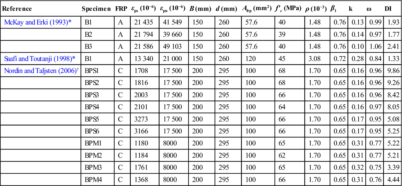
Notes: A = AFRP; C = CFRP; εps = FRP strain in service; εpu = ultimate FRP strain; B = width of beam; d = effective depth of beam; Afrp = cross-sectional area of FRP; f′c = concrete strength; ρ = reinforcement ratio; β1 = stress block factor for concrete; k= ratio of neutral axis depth to FRP depth; ω = constant shown in Equation [2.3]; DI = deformability index.
*Internally bonded.
†NSM bars.
2.10 Conclusions and future trends
This chapter has presented a comprehensive overview of the application of prestressed FRP composites for concrete structures in flexure with emphasis on practical perspectives. Commercially available FRP products were reviewed with their engineering properties. Existing provisions of codes and design manuals were evaluated, including their applications and limitations. Detailed flexural responses of concrete members with prestressed FRP composites were examined. The following conclusions can be drawn:
• FRP materials for prestressed concrete application (either bonded or unbonded) should carefully be selected for their usage. AFRP tendons were susceptible to ultraviolet rays; however, they had good resistance to fatigue. GFRP demonstrated significant creep deformation. CFRP exhibited favorable temperature resistance and excellent long-term behavior.
• Various techniques were used to prestress FRP composites, namely, artificial camber, external apparatus, and direct-tensioning methods. A high level of prestressing force (e.g., 50–60% ultimate) was applied for internally bonded cases, whereas a relatively low level (e.g., 20–40% ultimate) was used for externally bonded and unbonded applications. Prestressing levels significantly influenced the flexure of concrete members with prestressed FRP composites, such as deformability, cracking, deflection, and failure modes.
• Excessive crack widths warned of the imminent failure of FRP-prestressed concrete members, rather than significant deflections that were typically observed in steel-prestressed concrete members. Long-term prestress losses of FRP-prestressed members were lower than those of steel-prestressed members because of the low modulus of FRP composites.
• Concrete members with unbonded FRP composites demonstrated larger deflections and fewer, but wide, crack widths when compared to the members with bonded FRP composites. These observations were attributed to the stress-sharing mechanism between the FRP and the concrete.
• Bond characteristics of prestressed FRP composites affected the flexure of concrete members. FRP tendons required shorter transfer and development lengths than seven-wire steel strands. This was due to the specially-treated surface of FRP tendons, such as sand-coated, fiber-wrapped, or indented. Insufficient bond triggered premature failure of prestressed FRP composites from strengthened concrete members. Adequate anchor systems precluded such an undesirable failure mode.
• Attention should be paid to the deformability of FRP-prestressed members because FRP composites do not exhibit yield characteristics. The level of initial prestress was the most contributing factor to deformability. Additional internal reinforcement substantially improved the deformability of concrete members with prestressed FRP composites.
Although the application of prestressed FRP composites for concrete structures has been well established over a decade, there still exists a paucity of understanding of the behavior of such structures. The following recommendations are made to further advance the state-of-the-art of prestressed concrete structures:
• Detailed stress transfer mechanisms from prestressed FRP tendons to concrete should be examined. Progressive damage propagation induced by stress concentrations along the FRP-concrete interface needs to be studied. Meso-scale finite element modeling may be a recommended approach.
• More experimental investigations are necessary to promote the cutting-edge technologies (e.g., NSM FRP and prestressed FRP laminates) to the industry sector. A practical anchor system should be developed for prestressed NSM FRP methods for site application. Predictive models for such innovative methods need to be developed for design professionals.
• Durability of externally unbonded and bonded FRP composites should be examined, including a combination of environmental effects and stress concentrations at deviators and anchorage. Long-term characteristics of FRP, including bond degradation, also need a due consideration to warrant the field application of prestressed FRP composites.
• Code and design manuals should include the state-of-the-art application of prestressed FRP composites. An upgrade of existing provisions may be necessary; for example, the ACI-440.4R-04 document should provide specific limits for the deformability index and should include provisions for long-term performance.
• More field application incorporated with advanced sensing technologies is recommended to monitor the actual performance of prestressed FRP composites.
2.11 Acknowledgment
The authors gratefully acknowledge financial support provided by the Natural Sciences and Engineering Research Council of Canada (NSERC) and Intelligent Sensing for Innovative Structures (ISIS Canada).