
Repair of deteriorated bridge substructures using carbon fiber-reinforced polymer (CFRP) composites
M.E. Williams, Walter P. Moore and Associates, Inc., USA
Abstract:
This chapter presents a case study in the evaluation and repair of a 10-year-old highway bridge with substructures undergoing moderate to severe premature concrete deterioration and expansion due to alkali-silica reaction (ASR). Detailed visual observations of distressed conditions, structural analysis, and results of laboratory materials testing are presented as contributors to the development of a repair course of action. Carbon fiber-reinforced polymer (CFRP) composite applications for confinement and anchorage concepts are discussed as they relate to the structural repair methodology presented. CFRP testing procedures are discussed to ensure quality control in the repair implementation.
Key words
alkali-silica reaction (ASR); concrete bridges; premature concrete deterioration; CFRP
9.1 Introduction
The condition of an aging highway bridge infrastructure continues to be a subject of concern. The vast majority of bridges built to last 50 years in the USA now have an average age of 43 years. According to the National Bridge Inventory (NBI), one out of every four bridges is structurally deficient and in need of repair or functionally obsolete. As the cost of new bridge construction continues to soar, bridge repair, where possible, has generally become more economical than bridge replacement. Increasing transportation demands, and increasing economic impacts of bridge traffic closures, have been an impetus for pursuing durable and long-lasting repair solutions with minimal impact on bridge operations.
Concrete bridge deterioration can be caused by many factors. Bridges can experience distress due to growing traffic volumes, higher loads, and harsh environments. Bridges can also experience premature concrete deterioration due to material defects or adverse reactions of the concrete constituents. In certain instances, premature concrete deterioration can be more severe than progressive deterioration from corrosion or other related material damage mechanisms. For concrete bridges, alkali-aggregate reactions such as the alkali-silica reaction (ASR) can be detrimental, leading to the potential loss in structural capacity and uncertain bridge life expectancy. This chapter presents a case study in the evaluation and repair of bridge substructures experiencing premature concrete deterioration, using carbon fiber-reinforced polymer (CFRP) composites.
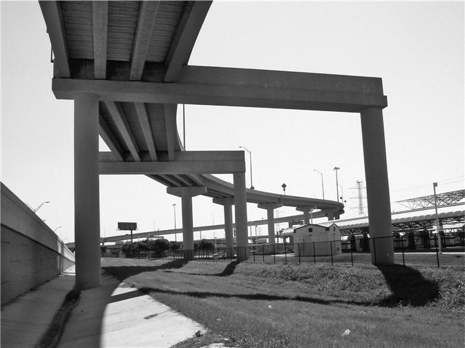
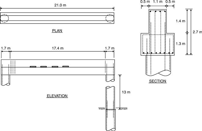
The subject of the case study is a concrete bridge that serves as a major connector for a high traffic volume toll road and has been in service for approximately 10 years. The multi-span bridge consists of precast concrete beams supported by cast-in-place reinforced concrete straddle bents, as shown in Fig. 9.1. Two concrete straddle bents in this case study span over an easement designated for future light rail expansion. The straddle bents are approximately 12 m in height, with inverted T-beams spanning approximately 17 m between two concrete 2 m diameter columns (Fig. 9.2). The two straddle bents are similar in design, and are separated by approximately 30 m. Both straddle bents are supported on drilled pier deep foundations. The straddle bents and bridge were constructed in accordance with the original design drawings and specifications.
9.2 Investigating deterioration of concrete in bridges
A prior routine bridge inspection noted cracking distress in the concrete bent substructure, particularly at the ends of the bent beams. Based on a review of bridge maintenance documents, cracking was believed to have initiated approximately 5 years after construction. An in-depth inspection was conducted to study the nature and cause of the cracking, in order to develop a future course of action for repair.
A close-up evaluation of the bridge substructures in this case study was performed in order to understand the nature and extent of the concrete deterioration. The investigation proceeded with a visual investigation of the substructures, followed by non-destructive evaluation, and concrete materials testing in a laboratory. The findings of these three phases of the investigation established the nature and causation of the observed concrete deterioration.
9.2.1 Visual investigation
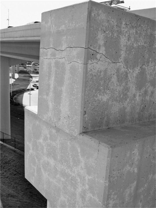
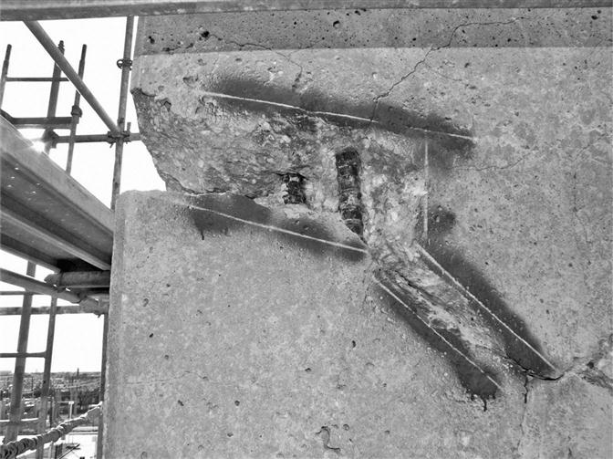
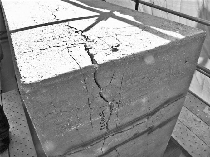
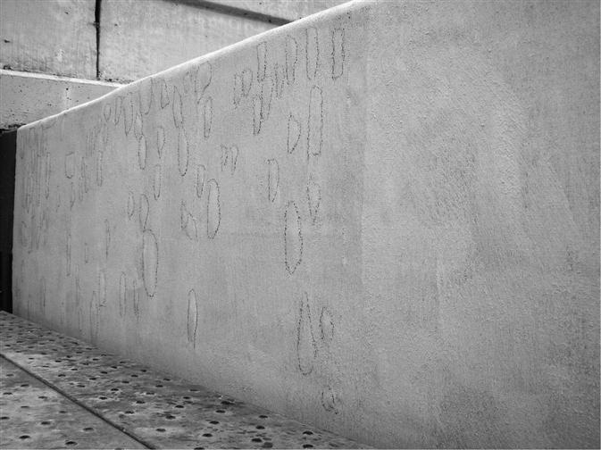
The primary means of visual evaluation was by up-close observations using aerial lift access. Concrete distress conditions were documented by way of field notes and crack mapping. Predominantly, the two straddle bent beams exhibited map cracking on all surfaces, with visible white staining exuding from cracks, as shown in Figs 9.3 and 9.4. Crack widths ranged from hairline to 3 mm on the surface of the bent beams. Severe concrete deterioration, in the form of wide cracking and concrete spalling, was observed at the ends of the bent beams (Fig. 9.5). At these locations, concrete crack widths up to 12 mm were recorded. Less notable map cracking was also observed near the top of the reinforced concrete columns supporting the substructure bent beams.


9.2.2 Non-destructive evaluation
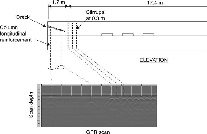
Non-destructive evaluation techniques were deployed to study the concrete deterioration in the two straddle bents. The substructure elements were scanned using ground (surface) penetrating radar (GPR) to identify the presence of reinforcing steel and to verify as-built conditions. Where possible, the bent beams were scanned in a single horizontal pass for side-by-side comparison with the as-built construction drawings. As shown for a particular bent beam end in Fig. 9.6, the horizontal GPR scan of the T-beam revealed conformance of reinforcing steel stirrups and longitudinal column steel placement with the as-built drawings. This finding was typical for the placement of reinforcing steel at both straddle bent beam end locations. The reinforcing steel placement was a key factor in determining the type and extents of the CFRP repair solution discussed later in this chapter.
Acoustic sounding techniques were deployed to obtain measurements of crack depth. Impact-echo testing was conducted at cracked concrete elements at selected locations. Impact-echo testing showed typical crack depths of 50–150 mm at locations of map cracking. Most notably, these crack depths exceeded the concrete clear cover at the reinforcing steel. Further testing of the bent beam ends showed full depth cracking, through a bent beam width of approximately 1.1 m. Crack depth measurements were further corroborated with crack length measurements along cores excised through cracks.
9.2.3 Concrete materials testing
Although there were some visual cues to possible mechanisms causing premature concrete deterioration, laboratory testing of excised concrete specimens was utilized to identify the specific deterioration mechanism. Exploratory coring was conducted to evaluate the concrete material properties and deteriorated condition of the concrete. Core samples were excised to obtain representative samples of deteriorated (cracked) and non-deteriorated concrete areas for subsequent laboratory testing and comparative study.
Concrete petrography was conducted on excised specimens at a testing laboratory in accordance with ASTM C 856 (standard practice for petrographic examination of hardened concrete) to study the cause of the concrete deterioration. Concrete samples were cut and examined under a stereomicroscope at 45 times magnification, and then as thin sections under polarized light up to 400 times magnification. The petrographic analysis indicated that the general quality of the original concrete was good, based largely on paste properties, water–cement ratio, and consolidation. The excised concrete cores, however, showed signs of randomly-oriented microcracks under microscopic evaluation, with evidence of ASR gel formation in voids and around quartzite aggregate particles. The ASR gel reaction product in the presence of moisture was believed to be the primary contributor to the expansion within the concrete and subsequent premature concrete deterioration. If left unchecked, further expansion of the ASR gel would lead to continued and more severe concrete deterioration of the bridge substructure.
Concrete deterioration due to ASR gel expansion can be influenced by concrete confinement, degree of restraint, and placement of reinforcing steel to control concrete cracking. In focusing on the substructure beam ends experiencing the most severe cracking, a review of the as-built construction drawings revealed the placement of limited reinforcing steel stirrups at the substructure beam ends. While additional reinforcing steel was not required for structural design purposes, the lack of confining steel stirrups provided ripe opportunity for ASR gel expansion in the presence of moisture. In addition, column longitudinal reinforcing steel extending up into the substructure bent beams for continuity was curtailed just below where the most severe cracking developed at the beam ends (Fig. 9.6).
9.3 Analysis of concrete deterioration in bridge substructures
The evaluation of structures undergoing premature concrete deterioration continues to be the object of research work seeking to incorporate long-term effects from deleterious reactions such as ASR. Finite element models of structural behavior, including expansive behavior of concrete gravity dams due to alkali-aggregate reactions, have been developed by Léger et al. (1996), Malla and Wieland (1999), and Sellier et al. (2009). While the finite element models reported in these research works have been validated with experimental test data, additional work is needed for general use on concrete bridge structures. Research has also been conducted to predict the swelling pressure of concrete undergoing expansion due to ASR. Work by Pike (1967) reported expansive pressures for mortars confined in a special metal container ranged from 2.5 to 14 MPa. Subsequent work by Lenzner and Ludwig (1978) measured expansive pressures of 2.5 to 4 MPa in mortars constrained with reinforcing bars. More recent work by Ferraris et al. (1997) measured expansion pressures ranging from 2 to 9 MPa depending on the level of reactivity in the concrete test specimens.
While considerable research has been conducted on ASR in concrete test specimens, there is limited published literature on the structural analysis of concrete bridge elements undergoing ASR expansion and subsequent deterioration. Accordingly, the bridge analysis presented in this case study relies on fundamental principles of structural mechanics with material behavior assumptions for expansive pressures exerted within the concrete bridge elements.
As previously shown, premature concrete deterioration was on-going in two concrete substructures. The straddle bent beams were undergoing map cracking throughout and severe cracking and splitting at the bent beam ends. Given the apparent cracking at the surface and confirmation of crack depths beyond the reinforcement cover, the substructure beams were suspected of undergoing expansive stresses exceeding the tensile strength of concrete (modulus of rupture). For the bridge substructures in this case study, the modulus of rupture was calculated to be approximately 4 MPa based on a concrete compressive strength of 42 MPa (AASHTO, 2012). Computer modeling of expansive behavior of rectangular or inverted T-shaped sections to replicate the level of concrete surface cracking would have been a complex endeavor involving nonlinear material behavior.
The extents of concrete cracking were considered in assessing the structural capacity of the substructures. Despite extensive map cracking and severe concrete deterioration at the bent beam ends, the concrete structure appeared to be generally intact, based on acoustic (hammer) sounding, and devoid of corrosion-related activity. Structural analysis of the substructure bent beams showed adequate structural capacity based on the original design parameters. However, knowing the substructures were undergoing irreversible concrete deterioration and the indeterminacy of the substructure capacity due to extensive cracking, structural remediation was the prudent course of action. Due to the expansive nature of ASR, structural remediation by confinement of the expanding concrete elements was required. This confinement was achieved by application of CFRP composites to the straddle bent beams.
9.4 Repair of bridges using carbon fiber-reinforced polymer (CFRP) composites
Repair of bridge substructures undergoing premature concrete deterioration can be achieved using a number of methods. Given the overwhelming need to keep the bridge open to service, partial demolition and repair or section enlargements were dismissed as repair options due to their potential functional and esthetic impact, respectively. Steel jacketing was also considered, and dismissed due to potential long-term maintenance issues. Repair using CFRP composites was preferred, due to its small and light footprint and ease of application while the bridge was in service. Among composite strengthening materials available for concrete, CFRP was preferred to glass-fiber or aramid reinforcement for exterior environments exposed to moisture. The high tensile strength of CFRP composites was also a compelling factor when selecting the material for the repair solution. The end goal of the repair was to counteract expansive pressures exceeding 4 MPa and subsequent surface cracking induced from ASR.
9.4.1 Design basis
In the repair methodology, CFRP composites were designed in a manner to provide external confinement of the bent beams. Research and experimentation in the confinement of concrete elements using CFRP has produced varied results. CFRP composites are more effective in confining circular concrete elements (i.e. columns). Confinement of non-circular concrete sections using CFRP can be achieved to a lesser extent using an equivalent diameter and shape factors (ACI, 2008). An important distinction to make in this case study is that CFRP was provided to confine further concrete expansion rather than to provide additional concrete compressive strength or joint confinement, as is the typical application for CFRP confinement in axially loaded members. In addition, some confinement is already provided by way of the reinforcing stirrups in the bent beams at locations of map cracking. Ideally, confinement and arrestment of future cracking would be achieved by a combination of existing reinforcing stirrups and external CFRP application. One drawback of this CFRP repair methodology is that the concrete element wrapped in CFRP must first expand in order to engage the CFRP and initiate restraint through confinement. This is somewhat counterintuitive, in that the CFRP composites are being provided to prevent further expansion due to ASR. However, applications of CFRP for confinement can be justified considering that some residual expansion is to be expected given the latent moisture conditions contributing to ASR within the bent beams.
CFRP composites were also designed to control expansion at the beam ends where there were minimal steel reinforcing stirrups. Calculation of the amount of CFRP composite strengthening was achieved by determining the design strength of the reinforcing stirrups at the typical spacing within the bent beam, had they been provided at the bent ends. Computation of the CFRP material requirements was similar to that for shear strengthening.
9.4.2 CFRP design for substructure beam
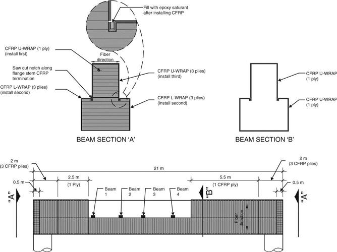
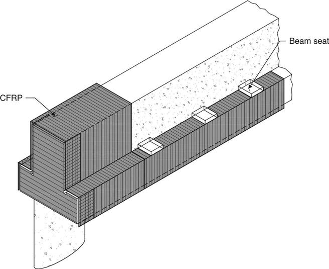
CFRP composites were designed for placement in locations to control concrete expansion along the straddle bent beams. A single ply of CFRP was designed for application along the beam where there was extensive map cracking. Given the angular geometry of the inverted T-beam, a single wrap was not possible, due to re-entrant corners. CFRP wrapping was therefore designed in two pieces. A single ply CFRP was designed to be applied as a three-sided U-wrap to the top leg of the inverted T-beam and a three-sided U-wrap on the flange of the inverted T-beam (Fig. 9.7 – Section ‘B’). Since the confinement procedure was designed in two pieces, CFRP end anchorage was provided to create pseudo-continuity between top and bottom of the beam in CFRP applications. End anchorage was provided by saw cutting a slot in the beam and embedding saturated plies in resin in the slot (Fig. 9.7). A single U-wrap application to the bottom flange of the beam was provided where access to the top leg of the inverted T-beam was not possible due to interference with the precast bridge beams and bearing seats (Fig. 9.8).
9.4.3 CFRP design for substructure beam ends
CFRP composites were designed for placement in locations to control concrete expansion at the straddle bent beam ends. In the case of the beam ends, a horizontal CFRP application was designed to control lateral expansion of the outside face of the bent beam end. Additionally, calculations showed that three vertical plies of CFRP would be required to supplement the existing minimal reinforcing steel stirrups, over a distance of approximately 2 m. These three plies were designed to be applied as a three-sided U-wrap to the top leg of the inverted T-beam. The CFRP installation drawings provided work phasing such that the horizontal CFRP application at the outside face of the beam was applied first (to the top leg and then bottom flange of the inverted T-beam) followed by the vertical U-wrap application (see Fig. 9.7 – Section ‘A’).
9.4.4 CFRP design specifications
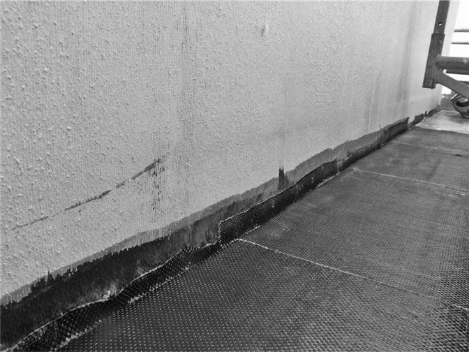
Drawings and technical specifications were developed prior to the application of CFRP composites. Documentation for concrete surface preparation was provided to include the removal of existing paint finishes on the concrete surfaces as well as surface roughness criteria using contained abrasive blasting. Although most CFRP confinement designs are generally not bond critical, surface roughness was specified to enhance bond to control concrete surface expansion. Procedures for crack repair were also provided in this construction documentation. Cracks with widths less than 6 mm were filled by injection of epoxy. Cracks with widths exceeding 6 mm, at the bent beam ends for example, required additional concrete removal and patching with concrete repair materials (Figs 9.9 and 9.10).
Several approved CFRP systems were specified for possible use on the project. Each system provided a layered application approach consisting of a primer, epoxy putty for surface irregularities, saturant, CFRP fabric, and protective top coat. The CFRP composite could be applied using either a wet or dry layup, depending on the contractor’s repair approach. A protective UV stable coating was specified for application over the finished CFRP composite. The coating was color-matched to other coated concrete surfaces in order to minimize the visibility of the CFRP application.
9.5 Review of CFRP repair of bridge substructure
Installation of the CFRP composite strengthening for the substructure elements was overseen for conformance with the repair design specifications. A mock-up was first installed to verify the proper CFRP application steps. Preparation of the concrete substrate to receive the CFRP was reviewed throughout the project, as proper surface preparation is critical to developing the necessary bond between the CFRP and concrete surface. The concrete surface was also observed to be sound and free of delaminations prior to the CFRP application. Temperature and relative humidity readings were recorded during mixing and application of the CFRP components. Finally, material batch numbers were logged for each application area in the event of a location-specific defect in the CFRP installation.
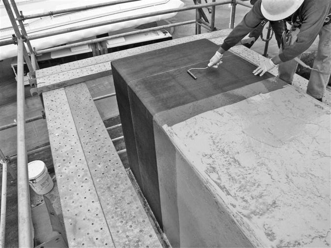
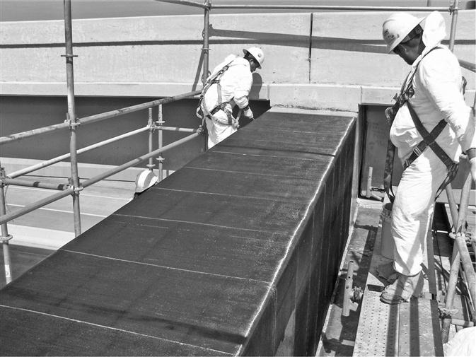
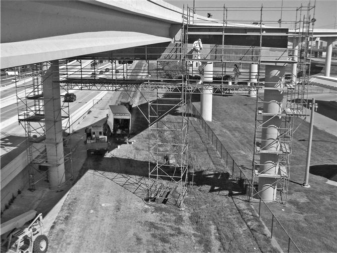
The CFRP composite application occurred in multiple phases. CFRP wrapping began at the end of each straddle bent beam (Fig. 9.11). CFRP wrapping then proceeded along the top of the bent beam (Fig. 9.12). CFRP was then applied to the bottom of the inverted T-beam and anchored into the slots previously installed along the beam (Fig. 9.13). Throughout this process, a work platform for the CFRP installation was provided by system scaffolding (Fig. 9.14).
CFRP installations were visually reviewed during and after application phases. Where possible, voids and delaminations were corrected prior to initial set of the CFRP composite. Such defects can occur due to various factors including sagging of CFRP material, outgassing due to temperature variations, improper saturation, and improper rolling and finishing. Defects noted after initial set of the CFRP composites were marked for repair. As discussed later in this chapter, excessive delaminations necessitated removal and reinstallation of CFRP composites (Fig. 9.15).
9.6 Site testing of CFRP repair and laboratory testing of materials
In addition to visual reviews of the CFRP installation, various site testing methods were employed to check the CFRP installation for conformance with the design specifications. Site testing methods include bond testing, infrared thermography, and acoustic (impulse response) testing.
9.6.1 CFRP bond testing
In this case study, CFRP test patches were installed for each application day and batch of resin used. Patches were tested for adhesion after curing to ensure conformance with ASTM D7522/D7522M–09 (standard test method for pull-off strength for FRP bonded to concrete substrate). A minimum pull-off tensile strength of 1.4 MPa was specified for bond.
9.6.2 Acoustic sounding
Acoustic sounding techniques were utilized to rapidly detect CFRP bond defects that were not visible during initial inspection. Delaminations detected by acoustic sounds, typically light tapping, were noted to have a dull, hollow sound upon testing. Although the testing can be performed quickly, there can be a high degree of inaccuracy, often leaving voids under the CFRP systems undetected. Those defects that are detected can be marked and subsequently repaired after acoustic sounding.
9.6.3 Infrared thermography
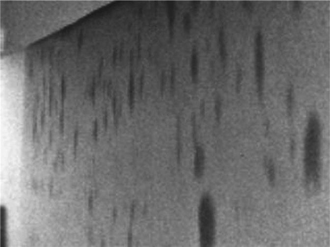
Infrared (IR) thermography is the science of acquisition and analysis of thermal information from non-contact thermal imaging devices. IR thermography detects emitted radiation in the infrared range of the electromagnetic spectrum. This corresponds to wavelengths longer than the visible light portion of the spectrum. Thermal imaging can therefore be utilized to detect defects in the CFRP installation that may not be visible. Voids or delaminations in the CFRP installation are shown with a unique thermal signature due to entrapped air between the CFRP composite and the concrete substrate. As shown in Fig. 9.16, CFRP delaminations exhibit a dark thermal signature in comparison to well bonded CFRP applications. As such, defects were marked and subsequently repaired after thermal inspection.
9.6.4 Impulse response testing
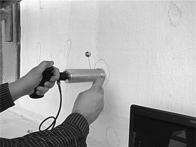
Impulse response is a non-destructive testing technique used to evaluate the integrity of concrete elements. In this test, a low-strain impact is applied to excite the structure and the response of the structure is measured. The concrete element is struck by using a small impactor, which has a built-in load cell that measures the impulse imparted. The response (vibration) of the concrete element is monitored by a velocity transducer (geophone) placed adjacent to the impact location. The geophone is connected to a data acquisition and processing system, which calculates the dynamic mobility as a function of the frequency of the excitation. The dynamic mobility was analyzed as a secondary means to characterize the condition of the CFRP composite and concrete substrate conditions, and the probability of delaminations in the CFRP application that may not be visible at the surface. Defects identified by impulse response testing were marked and subsequently repaired after inspection (Fig. 9.17).
9.6.5 Laboratory testing of CFRP materials
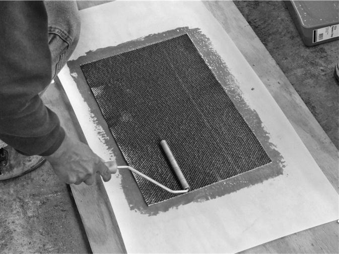
Laboratory testing is typically conducted to verify the mechanical properties of the CFRP composite. In this case study, witness panels were constructed by the repair contractor for each application day and batch of resin used in order to ensure quality control. Three-ply CFRP witness panels were created to match the installation condition on the straddle bents (Fig. 9.18). A portion of these fully cured witness panels were sent to a qualified testing laboratory with experienced personnel to validate the CFRP material properties with those used in the design. Witness panel testing was conducted to determine the CFRP composite thickness, tensile strength, modulus of elasticity, and percent elongation. The test results were then compared to the published mechanical properties from the CFRP material manufacturer.
9.7 Dealing with defects in CFRP repairs
Some defects are likely to occur given the labor intensive process of mixing multi-component materials and applying CFRP composites to existing concrete elements at a bridge site. ICC-AC 178 (2008) provides the following guidelines for judging CFRP defects and possible recourses for repair:
• Small entrapped air pockets and voids (approximately 1.6–3.2 mm in diameter) naturally occur in mixed resin systems and generally do not require repair.
• Except at the edges or boundaries, delaminations of less than 130 square mm are generally permissible.
• No more than ten delaminations of this size shall be allowed per 1 m square of the laminated area.
• Any delaminations spanning more that 5% of the surface area shall be repaired by any method approved by the engineer.
In this case study, several CFRP U-wrap applications to the bent beams had delaminations well in excess of the 5% judging guideline, thereby requiring removal and replacement. The CFRP wraps in question experienced sudden outgassing during initial set due to rapid temperature variations between the application faces. Under direct sun exposure, the outgassing resulted in bubble formations through the CFRP application strips. The contractor removed the CFRP wraps in this location and successfully reinstalled the material at a later date.
9.8 Conclusions
This case study has provided a methodology for assessing and repairing concrete bridge substructures undergoing premature concrete deterioration. Once the deterioration was diagnosed and attributed to ASR expansion, a repair scheme using CFRP composites was implemented for two straddle bent substructures. It is worth noting that this major connector bridge was evaluated and repaired without removing the bridge from service. CFRP applications in lieu of straddle beam replacement or section enlargement provided a cost-effective solution to mitigating ASR expansion and further concrete deterioration. The CFRP repair also proved to be suitable from an esthetic standpoint, as it generally goes unnoticed by the casual observer (Fig. 9.19). The CFRP repair has been in place for several years and appears to be performing as intended, based on periodic visual reviews. Long-term monitoring of these concrete members will help to validate the success of the remedial repairs in mitigating future concrete deterioration.