
Engineered cementitious composites for bridge decks
M. Li, University of Houston, USA
Abstract:
Engineered cementitious composites (ECCs), by reducing the brittle nature of concrete, have opened a new world of possibilities to enhance the safety, durability, and sustainability of civil infrastructure. With a strategically designed microstructure, ECC features incredible ductility under tension, previously only seen in ductile metals. Cost savings can be realized through more efficient design, and less frequent maintenance and repairs. When long-term environmental impacts are accounted for, the ECC advantages over concrete become even more compelling. This chapter presents the ECC fundamentals related to bridge construction, including the basics of material design theory, mechanical and durability characteristics, and application in bridges.
Key words
engineered cementitious composites; micromechanics; ductility; multiple cracking; durability
7.1 Introduction
In the past decades, great strides have been made in developing high-performance-fiber-reinforced cementitious composites (HPFRCCs). HPFRCCs were first classified by Naaman and Reinhardt1 as materials that can achieve different degrees of tensile ductility, often accompanied by a macroscopic pseudo-strain-hardening response after first-cracking. Under this definition, HPFRCC is differentiated from normal fiber-reinforced concrete (FRC), which has a tension-softening response (Fig. 7.1).2 Efforts to design tensile ductility into cementitious materials started in the 1970s, and have mainly focused on using continuous aligned fibers or large volumes of discontinuous fibers. Aveston et al.3 and Krenchel and Stang4 achieved tensile ductility hundreds of times that of normal concrete using continuous, aligned fibers in cementitious materials. Textile reinforced concrete materials, representing the modern version of continuous FRC, were developed by Curbach and Jesse5 and Reinhardt et al.6 Pultruded continuous FRC was recently developed by Mobasher et al.7 Additionally, cementitious composite materials using discontinuous fibers at high dosage (4–20%) in cement laminates8 or in slurry infiltrated fiber concrete (SIFCON)9,10 attained higher tensile strength and strain capacity than normal concrete, but much lower tensile ductility than continuous fiber and textile reinforced cementitious materials.

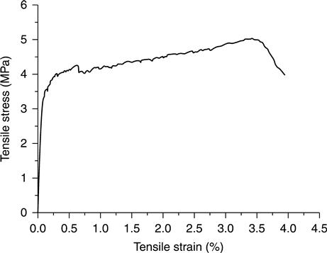
In recent years, a new class of HPFRCCs has emerged. Engineered cementitious composites (ECC) represent a family of fiber-reinforced cementitious composite materials that uniquely feature tensile ductility and intrinsic crack width control capacity with a moderate amount (2% by volume) of short discontinuous fibers such as polyethylene, poly-vinyl alcohol, or polypropylene fibers.11,12 While containing similar ingredients to concrete or FRC, the microstructure of ECC can be deliberately tailored through the use of micromechanical models to achieve tensile strain-hardening behavior and ductility levels approximately 200–600 times that of concrete under tension, thereby leading to delayed fracture localization (Fig. 7.2).13,14 The fiber/matrix interfacial micromechanical parameters are strategically tailored to allow ECC to dissipate energy through multiple microcracking with crack widths less than 100 μm (Fig. 7.3). The tensile strain-hardening behavior of ECCs significantly differentiates them from other FRCs such as steel, polymeric, glass, and carbon FRCs, which exhibit tension-softening behavior.
The name ECC was adopted by its original developers.11 The word ‘engineered’ emphasizes the micromechanics-based design and manipulation of the material microstructure to achieve specific composite behavior dictated by particular structural applications. In this way, ECC represents a family of materials without fixed ingredients or mixing proportion; more importantly, it also represents a versatile design philosophy. Microstructure design, rheology tailoring, and composite material science together serve as powerful tools to guide ECC material development for targeted composite properties, and enable a meaningful linkage between materials engineering and structural performance design.15,16 It should be noted that the design of ECC is not dependent on a certain type of fiber, although a large body of literature is on ECC incorporating poly-vinyl alcohol fibers. Nor does ECC rely on increasing fiber volume to achieve strain-hardening behavior. Instead, the ECC design philosophy emphasizes the synergistic interaction between fiber, matrix, and the fiber/matrix interface. An alternative name for ECC is strain-hardening cementitious composite (SHCC), given by RILEM TC HFC Technical Committee in 2006,17,18 emphasizing its tensile strain-hardening behavior as a constitutive law for structural engineering. Another name for ECC, given by Japan Society of Civil Engineers(JSCE), is multiple fine cracking fiber-reinforced cementitious composites,19 emphasizing the multiple fine microcracking behavior of ECC and its durability aspects.
The development and understanding of ECC is still evolving. This article presents some basic knowledge of ECC that does not cover the whole range of ECC materials that have been or are being developed. In the next section, the fundamentals of ECC design theory are introduced, followed by a section summarizing the mechanical properties and durability of ECC. The last section describes the implementation of a regular version of ECC, and a high early strength version of ECC in bridge-deck applications.
7.2 Engineered cementitious composites (ECCs) design theory
The design of ECC is based on micromechanics and fracture mechanics theory. Once the target ECC composite property is determined, it can be achieved through microstructure design coupled with rheology tailoring.
7.2.1 ECC design framework: scale linking
The micromechanics-based design theory of ECC was first established in the early 1990s.20,21 This theory links the measurable micromechanics parameters to the cracking propagation mode, and then to conditions for composite tensile strain-hardening. Scale linking is a fundamental characteristic of the ECC design approach, in which understanding and tailoring of microscale constituent parameters are the keys to achieving target macroscale composite behavior.16
As a composite material, ECC contains three main components: fiber, matrix, and fiber/matrix interface. Each component can be defined by a set of micro-parameters. Under uniaxial tension, ECC composites exhibit tensile strain-hardening behavior at the macroscale (mm–cm) through a multiple cracking process. Steady-state crack propagation is a necessary condition to ensure multiple cracking, which is governed by the fiber bridging properties across cracks at the mesoscale (μm–mm). The fiber bridging spring law across a crack, quantified by the fiber bridging stress vs crack opening relationship σ(δ), is the integration of the bridging force contributed by every single fiber bridging the crack. For an individual fiber, its bridging force for a given crack opening is determined by its debonding and pullout behavior from the surrounding matrix, and governed by fiber and interface properties at the microscale (nm–μm), as well as by fiber embedment length and inclination angle between the fiber axis and the crack face normal. In summary, the micromechanics model links microscale constituent parameters to fiber bridging constitutive behavior on the mesoscale; steady-state crack analysis links fiber bridging properties to tensile strain-hardening behavior on the composite macroscale. Once established, the model-based linking provides a systematic framework for optimizing ECC composite tensile properties with the minimum amount of fiber by strategically tailoring the microstructure at the smallest scale.16
7.2.2 Conditions for tensile strain-hardening
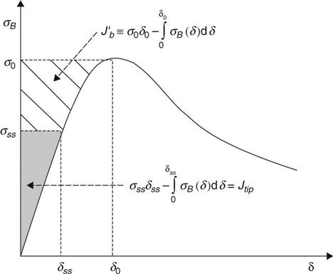
The tensile strain-hardening behavior of ECC is realized by tailoring the synergistic interaction between the fiber, matrix, and fiber/matrix interface using micromechanics theory. As a fiber-reinforced brittle mortar matrix composite, ECC's pseudo-strain-hardening behavior is achieved through sequential formation of matrix multiple cracking. The fundamental requirement for matrix multiple cracking is that steady-state flat crack propagation prevails under tension, which was first characterized by Marshall and Cox22 for continuous aligned fiber-reinforced ceramics, and extended to discontinuous fiber-reinforced cementitious composites by Li and Leung.20 To ensure steady-state cracking, the crack tip toughness Jtip must be less than the complementary energy ![]() calculated from the fiber bridging stress σ vs crack opening δ curve, as illustrated in Fig. 7.3 and shown in Equations [7.1] and [7.2].
calculated from the fiber bridging stress σ vs crack opening δ curve, as illustrated in Fig. 7.3 and shown in Equations [7.1] and [7.2].
[7.1]
[7.2]
where σ0 is the maximum bridging stress corresponding to the opening δ0, Km is the matrix fracture toughness, and Em is the matrix Young's modulus. Equation [7.1] employs the concept of energy balance during flat crack extension between external work (σ0 δ0), crack flank energy absorption through fiber/matrix interface debonding and sliding ![]() , and crack tip energy absorption through matrix breakdown (Jtip). This energy-based criterion determines whether the crack propagation mode is steady-state flat cracking or Griffith cracking,23 as illustrated in Fig. 7.4.
, and crack tip energy absorption through matrix breakdown (Jtip). This energy-based criterion determines whether the crack propagation mode is steady-state flat cracking or Griffith cracking,23 as illustrated in Fig. 7.4.

Apart from the energy criterion, another condition for pseudo-strain-hardening is that the matrix tensile cracking strength σc must not exceed the maximum fiber bridging strength σ0.
[7.3]
where σc is determined by the matrix fracture toughness Km and the preexisting internal flaw size a0 and distribution. While the energy criterion governs the crack propagation mode, the strength-based criterion controls the initiation of cracks. Satisfaction of both equations is necessary to achieve ECC strain-hardening behavior; otherwise, the composite behaves as a normal FRC, and results in tension-softening behavior.
7.2.3 Conditions for saturated multiple microcracking
For ECC materials with pseudo-strain-hardening behavior, high tensile strain capacity results from saturated formation of multiple microcracks. Once the steady-state cracking criteria are satisfied, the number of microcracks that can be developed is determined by (i) the maximum fiber bridging stress σ0, which is determined by fiber/matrix interface properties and fiber properties, and (ii) the matrix properties, in particular the pre-existing flaw-size distribution, and the matrix fracture toughness. Considering that ECC is a non-homogenous brittle-matrix composite, first-cracking strength is determined by the largest flaw size in the section where the first microcrack is initiated. Its ultimate tensile strength is determined by the ‘weakest’ section, where the fiber bridging capacity (maximum bridging stress σ0) is the lowest among all sections subjected to the same level of stress. Therefore, the maximum fiber bridging stress σ0 at the ‘weakest’ section imposes a lower bound on critical flaw size cmc, so that only those flaws larger than cmc can be activated and contribute to multiple cracking. There also exists a minimum crack spacing controlled by interface properties, which imposes an upper bound for the density of multiple cracking.
Matrix imperfections, for example random distribution of pre-existing flaws, is one cause of the variation in crack spacing and tensile strain capacity. Therefore, a large number of flaws slightly larger than cmc are preferred for saturated multiple cracking and high tensile strain capacity. Flaws much larger than cmc will lead to a reduction in the net cross-section and fiber bridging stress at the crack section. Fiber dispersion non-uniformity is another contributor to the variation in tensile strain capacity and unsaturated multiple cracking. With a fixed fiber volume percentage, the maximum fiber bridging stress σ0 at the weakest section is determined by the degree of fiber dispersion uniformity in the composite. Fiber dispersion uniformity is directly influenced by the rheology characteristics of the fresh ECC during processing.24 Ideally, processing of ECC should optimize fiber dispersion to achieve a uniform random distribution state, thereby minimizing the probability of creating ‘weak’ sections with lower fiber content. By these means, the largest possible tensile strain capacity can be achieved by maximizing multiple cracking behavior.
7.3 ECC mechanical properties and durability
ECC's high tensile ductility, deformation compatibility with existing concrete, and self-controlled microcrack width lead to its superior mechanical behavior and durability under various loading and environmental conditions,25 as summarized below.
7.3.1 Tensile behavior
The sole method to validate the true ECC tensile strain-hardening behavior is through direct uniaxial tension test. This is because some tension-softening materials can exhibit ‘pseudo-deflection hardening’ under bending test, depending on the geometry of the specimen. Figure 7.2 shows the typical tensile strain-hardening behavior of ECC under uniaxial tension, with tensile strain capacity approximately 3.5%, which is 350 times that of concrete and FRC. Such strain-hardening and ductile behavior indicates high fracture energy of the material for damage tolerance. Despite the difference in mix design, the ECC tensile stress–strain curve generally follows the same pattern containing three stages:
(1) the initial elastic stage, characterized by Young's modulus;
(2) the strain-hardening stage, accompanied by multiple microcracking formation. During this stage, the width of each microcrack slightly increases up to a strain level of 0.5% approximately, and then remains nearly constant while the increasing applied strain only increases the number of microcracks. This stage is characterized by first-cracking strength (i.e. the stress when the first microcrack occurs), ultimate tensile strength (i.e. the peak stress before localized fracture occurs), and the strain capacity of the material (i.e. the strain corresponding to peak stress). As the uniaxial tension test is conducted under displacement control, small load ‘drops’ on the curve correspond to the released energy during the formation of each microcrack
(3) The tension-softening stage, accompanied by the formation of a localized fracture at one of the microcracks and the continuous decrease in the ambient load. At this stage, ECC behaves similar to tension-softening FRC materials.
7.3.2 Compressive properties
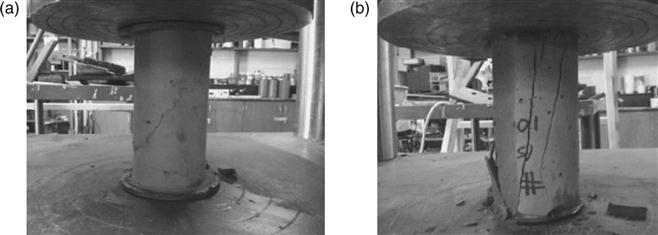
The compressive strength of ECC typically ranges from 30 to 100 MPa,26 depending on its mix design. The most commonly studied version of ECC, M45, has a 28-day compressive strength of 50–60 MPa. The Young's modulus of ECC is 20–25 GPa, which is lower than concrete because ECC does not contain any coarse aggregates in general in its mix design. This relatively low elastic modulus of ECC is desirable for limiting the tensile stress built up under restrained shrinkage conditions.27 The compressive strain capacity of ECC at 0.45–0.65% is slightly higher than concrete; the softening branch of ECC compressive stress–strain curve is longer, allowing for a more ‘ductile’ compressive failure mode with an approximately 45° final fracture plane, in contrast with brittle splitting failure mode of concrete or high strength concrete (Fig. 7.5).28
7.3.3 Inherent crack width control capacity
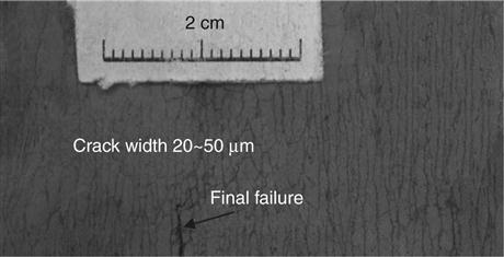
Concrete cracking is a result of the combined effects of mechanical loading and environmental conditions.29 Concentrated chloride exposure is one of the most severe and aggressive among all possible forms of environmental exposure for concrete structures.30 Serious concrete deterioration is generally initiated by concrete cracking under restrained shrinkage or stress concentration, which leads to accelerated penetration of aggressive agents, subsequent corrosion of embedded reinforcing steel, and spalling of concrete cover.31–34 Maximum allowable crack widths are thereby required in various codes and specifications for the design of reinforced concrete structures exposed to aggressive chloride environments. The allowable maximum crack width ranges from 150 to 300 μm,35–39 with the most stringent requirements specified by JSCE38 and American Concrete Institute(ACI) 224R.25 According to ACI 224R,29 the maximum crack width at the tensile face of reinforced concrete structures is specified as 150 μm for exposure conditions of seawater, seawater spray, wetting, and drying, and 180 μm for deicing chemical exposure. As the microcrack width of ECC formed during its strain-hardening stage is intrinsically limited to below 100 μm (Fig. 7.6),40 which is independent of structural geometry and applied deformation, steel reinforcement is not required to control crack width even for the most stringent allowable crack width requirement.
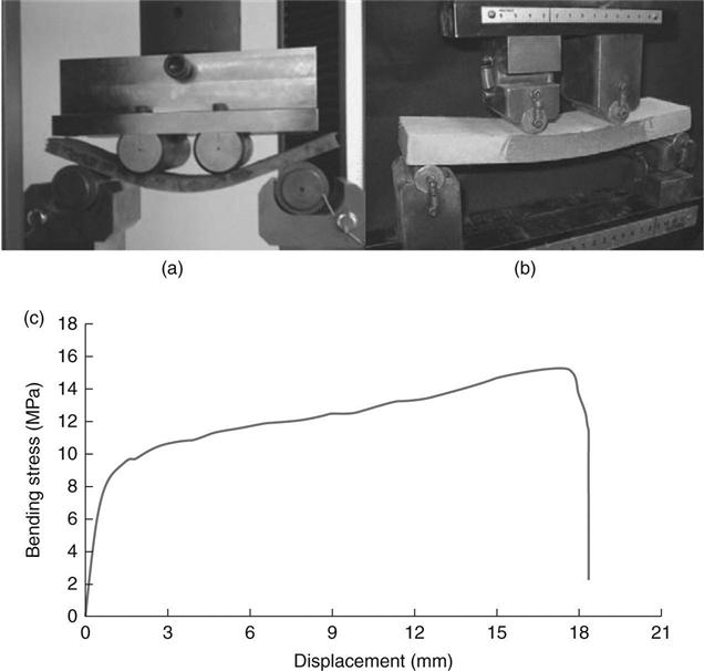
7.3.4 Flexural behavior
The popular nickname for ECC – ‘bendable concrete’ – results from its ductile flexural behavior. Under four-point bending, ECC first undergoes an elastic stage, followed by a deflection-hardening behavior accompanied by the formation of a number of microcracks on the tensile side of the specimen. This allows ECC to undergo a large curvature without fracture failure under excessively applied deformation. The deflection-hardening response of ECC reflects its tensile ductility, and is thus an intrinsic property. This is not the case for tension-softening FRC, for which, as beam specimen height increases, deflection hardening becomes more difficult to attain.41 Highly deformed ECC coupon and beam specimens are shown in Fig. 7.7.14
7.3.5 Abrasion and wear resistance
To evaluate ECC's abrasion and wear resistance for bridge-deck and roadway applications, surface friction and wear track testing according to Michigan Test Method 111 was conducted in conjunction with Michigan Department of Transportation (MDOT)42 using a static friction tester (Fig. 7.8). These tests were conducted on a wet pavement surface with vehicle tires operating at 65 kph (40 mph). Initial friction forces between the tire and the ECC surfaces were determined. The ECC specimens were then subjected to 4 million tire passes to simulate long-term wear. After wearing, friction forces were again determined to evaluate deterioration or surface polishing during wearing. These final measured frictional forces are called the aggregate wear index (AWI). AWI values for the textured ECC samples range from 1.6 to 2.3 kN, which are higher than the required minimum AWI of 1.2 kN for Michigan trunkline road surfaces. The test results show that ECC has good abrasion and wear resistance to heavy traffic.

7.3.6 Freezing and thawing
Saturated concrete exposed to freeze–thaw cycles may experience disintegration. Reduced freeze–thaw resistance has also been found in some very high early strength concrete mixes,43 limiting their applications in cold regions. Freezing and thawing testing was conducted on non-air-entrained ECC and normal concrete prisms42 over 14 weeks based on ASTM C666A.44 After 5 weeks (110 cycles of freezing and thawing), the non-air-entrained concrete specimens had severely deteriorated and were therefore removed from the test. The non-air-entrained ECC specimens survived 300 cycles with no degradation of dynamic modulus (Fig. 7.9). The freeze–thaw durability factor of ECC was calculated as 100, far larger than 10 for the non-air-entrained concrete. Additionally, uniaxial tension tests were performed on ECC coupons after being exposed to 200 cycles of freezing and thawing, and revealed no significant decrease in tensile strain capacity. The freeze–thaw resistance of non-air-entrained ECC is attributed to its pore structure, which is influenced by (i) the entrapped air size and distribution during processing of the mixture with specific viscosity and fiber content, and (ii) the hydration process. The increased toughness (i.e. reduced brittleness) of ECC also leads to increased resistance to disintegration.

7.3.7 Restrained shrinkage cracking
Shrinkage of concrete, when constrained, often causes early-age cracking in concrete. The tensile strain capacity of ECC is two orders higher than its shrinkage strain. Therefore, ECC can accommodate the restrained shrinkage deformation to suppress localized cracking.40,45 Shrinkage ring tests were conducted to simulate the shrinkage of a freshly cast ECC layer constrained by a steel ring. In contrast with the localized cracking in the control concrete specimens, whose crack width increased as the shrinkage strain increased with time, the ECC layer exhibited a number of distributed microcracks with crack width under 100 μm. The width of these microcracks did not increase the shrinkage strain increased was time; instead, the number of microcracks increased. The results indicated that ECC does not require steel reinforcement to control shrinkage cracking.
In concrete repairs, shrinkage can induce repair surface cracking and repair/old interface delamination. As shrinkage deformation of the repair layer is restrained by surrounding concrete that has undergone most of its shrinkage, tensile stress can build up in the repair layer and cause surface cracking; a combination of tensile and shear stress can build up at the repair/old interface and lead to interface delamination. Cracking and delamination are the main causes that initiate numerous durability issues in concrete repairs. Li and Li45 experimentally (Fig. 7.10) and numerically validated that the high tensile ductility of ECC repair can accommodate its shrinkage deformation by forming multiple microcracks with tight crack width below 60 μm. By these means, tensile and shear stresses at the repair/substrate interface were relieved, so that both repair surface cracking and interface delamination were limited to below 70 μm. It was also found that for normal concrete repair, several localized cracks over 450 μm in width formed in the repair layer. For steel FRC repair, several localized cracks formed with widths larger than 120 μm. Since the cracks were bridged by steel fibers and could not open traction-free to accommodate the repair layer's shrinkage deformation, the interface delamination became much larger (280 μm) than concrete and ECC repairs.

7.3.8 Water permeability
The transport properties of concrete cover determine the time needed for the penetration of water or aggressive agents to reach the steel reinforcements. Transport mechanisms include permeation, diffusion, and capillary absorption. Permeability of cracked concrete scales with the third power of crack width,46,47 and a crack with width below 100 μm (50 μm for gas permeability) tends to behave like sound concrete. Wang et al.47 and Lepech and Li48 found that microcracked ECC exhibited nearly the same permeability as sound concrete, even when loaded to a tensile strain of 1.5% (Fig. 7.11). The low water permeability of ECC is due to its tight self-controlled crack width, which does not rely on the steel reinforcement ratio and is independent of the applied strain level, as long as the strain capacity of the material is not surpassed.

7.3.9 Chloride diffusion
The corrosion of steel in concrete is a major durability concern for reinforced and prestressed concrete structures, demanding significant amounts of repair and rehabilitation.49–52 When concrete is cast around steel reinforcements, a passivation film forms around the steel bars and protects them from corrosion initiation. However, chloride ions, whether airborne or from deicing salt or seawater, are often present, especially in coastal areas and snow regions where deicing salts are used. Corrosion starts when chloride ions pass through the sound or cracked concrete cover, reach the steel, and accumulate beyond a threshold concentration level. At this point the natural protection layer surrounding the steel becomes depassivated, if oxygen and moisture are present in the steel–concrete interface. The oxidation products generate expansive forces within the concrete, eventually causing the concrete cover to spall.53 Moreover, the cross-section of the reinforcing bar or prestressing strand is now diminished, leading to a reduction in the load carrying capacity of the concrete member. It is widely recognized that corrosion of reinforcing steel has led to the premature deterioration of many concrete structures in the United States, especially bridges and marine structures, before their design life was reached. Although corrosion is not the sole cause of all structural deficiencies, it is a significant contributor and has become a major concern.51,54
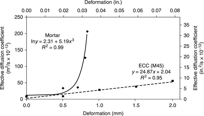
Corrosion initiation time is governed by the chloride diffusion coefficient. Chloride diffusion coefficients of ECC beam specimens were determined and compared with control reinforced mortar specimens (without coarse aggregates).55 The specimens were loaded under four-point bending to various deformation levels, and then were subjected to salt ponding of 3% chloride solution according to AASHTO T259–80.56 The chloride diffusion coefficients of unloaded and loaded specimens were determined based on the chloride concentration profile along the depth of the specimen. As shown in Fig. 7.12, the chloride diffusion coefficients were 6.75 × 10⁻¹² m2/s and 10.58 × 10⁻¹² m2/s for unloaded ECC and reinforced mortar, respectively. When the applied bending deformation increased, the chloride diffusion coefficients increased with a significantly faster rate for reinforced mortar than ECC. This was because the increasing deformation of ECC was accompanied by an increasing number of microcracks, while the crack width of each microcrack remained hardly changed; in contrast, the increasing deformation of reinforced mortar was accompanied by increasing crack width. It was further revealed that the chloride diffusion coefficient of ECC increased linearly with the number of cracks, whereas the diffusion coefficient of reinforced mortar was proportional to the square of the crack width. At the same level of applied deformation, the chloride diffusion coefficient of ECC was far lower than reinforced mortar, indicating a significantly longer chloride initiation time.
7.3.10 Corrosion resistance
In addition to prolonged corrosion initiation time, the high tensile ductility of ECC can lead to higher resistance to spalling induced by corrosion, and thus further prolonged service life. Şahmaran et al. (2008)57 conducted an experimental investigation on reinforced (R)/ECC cylinder with a single steel rebar embedded and subjected to accelerated corrosion by electrochemical method (Fig. 7.13). The corrosion-induced crack width of the mortar specimens increased with time as the steel corrosion progressed. Larger crack widths, up to 2 mm wide, were observed in mortar at higher levels of corrosion. On the other hand, crack widths of ECC remained nearly constant (~0.1 mm) with time as corrosion activity progressed, while the number of cracks on the surface of the specimen increased. The results of this study showed that ECC has significant anti-spalling capability as compared to conventional mortar. If 0.3 mm maximum crack width limit for outdoor exposure, as specified by AASHTO (2004),58 were used to represent the serviceability limit of reinforced concrete structures, the service life of reinforced ECC would be at least 15 times that of the reinforced mortar.

Reinforcement corrosion in mortar specimens resulted in a marked reduction in stiffness and flexural load capacity, as a result of mass loss of steel.57 After 25 h of accelerated corrosion exposure, the flexural strength reduced to about 34% of the original flexural capacity of the control mortar beam. In contrast, the ECC specimens after 50 h of accelerated corrosion exposure retained almost 100% of the original flexural capacity. Beyond 50 h, the flexural capacity decreased, but retained over 45% that of the original capacity, even after 300 h of accelerated corrosion exposure. Longitudinal cracks due to expansion of the corrosion products also affected the failure mode of the reinforced mortar under four-point bend loading. However, ECC deterioration due to the corrosion of reinforcement did not modify the ductile failure mode in ECC beams. Overall, the experimental results from this study suggest that the propagation period of corrosion could be safely included in estimating service life of a structure when concrete is replaced by ECC.
7.3.11 Fatigue behavior
ECC has greatly improved fatigue response compared with normal concrete and FRC. Suthiwarapirak et al.59 conducted flexural fatigue tests on ECC, and demonstrated higher ductility and fatigue life compared with polymer cement mortars commonly used in repair applications. Furthermore, fatigue loading does not seem to increase crack width. Kim et al. (2004)60 experimentally validated that after 100 000 cycles of fatigue loading, the crack width in the reference concrete link slab specimen increased from 50 μm to over 0.6 mm, while the crack width in the ECC link slab remained close to 50 μm.
7.3.12 Reflective cracking in repairs
In bridge-deck overlay repairs, premature reflective cracking is often the ultimate failure mode that limits repair service life.61,62–63 Concrete or hot mix asphalt (HMA) overlays are primary methods for rehabilitating distressed asphalt and Portland cement concrete pavements subjected to moderate and heavy traffic, including highways, bridge decks, and airfields.64 Before the more expensive option of removal and re-construction of existing pavements are undertaken, overlays can be used to provide smooth surfaces while utilizing the structure of existing concrete pavements.65,66 Reflective cracking is often the first distress that occurs in overlays.67 It is characterized as new cracks reflected through the overlay from pre-existing cracks or joints in the substrate under repeated traffic loads. In most cases cracks propagate through the new overlay during the first few years of service.68 Under severe conditions, a reflective crack can reach the surface of a 150 mm (6 in.) overlay in less than 1 year.69 Reflective cracking not only reduces the overlay load carrying capacity and service life, but also provides a path for aggressive agents to infiltrate the pavement or bridge-deck structure and cause early deterioration.70
Traditionally, efforts undertaken to reduce reflective cracking in overlay repairs have fallen into three broad categories71: (a) concrete slab fracturing, which includes rubblization, crack and seat (for plain concrete pavement), and break and seat (for reinforced concrete pavement); (b) stress-relieving interlayer, which is used between the concrete substrate and overlay, and includes paving fabric, modified HMA interlayer, geogrid, and other proprietary interlayers; and (c) modified overlay, which includes increasing overlay strength, increasing overlay thickness, adding fiber reinforcement, introducing saw and seal joints in HMA overlay, etc. If used appropriately, these methods can delay reflective cracking to a certain extent, although they will not fundamentally eliminate the fracture failure of the overlay.
Reflective cracking can be suppressed when ECC is used as the repair material.72 A layered repair system (Fig. 7.14) was investigated for resistance to reflective cracking and delamination under four-point monotonic and fatigue bending loading.16,73 This system contained a layer of repair material made of high early strength ECC (HES-ECC) or high early strength concrete cast on a substrate layer of old concrete with an initial vertical crack and interfacial delamination. When subject to monotonic loading, the HES-ECC layered repair system exhibited 100% increased load carrying capacity, and 5–10 times the deformation capacity of a concrete layered repair system. Instead of forming one single crack in the concrete repair layer, the initial interfacial crack would kink into the ECC repair layer, and then become trapped there. Upon additional loading, delamination resumed at the interface. The unique kink-trap-cracking behavior repeated itself with increasing loading till the flexural strength of HES-ECC was exhausted. In this way, repair spalling was successfully suppressed by using HES-ECC. Furthermore, when subject to the same level of fatigue loading, the HES-ECC layered repair system showed significantly longer service life than the concrete layered repair system (Fig. 7.15).


7.4 ECC application in bridges
ECC has been applied in bridge construction in the United States and in Japan, including repairs (Sections 7.4.1 and 7.4.2), rehabilitation (Section 7.4.3), and new construction (Section 7.4.4).
7.4.1 ECC patch repair
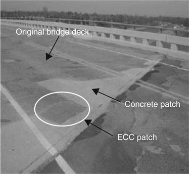
One of the earliest applications of ECC was a small patch repair on a bridge deck in the US.26,42 This application offers significant insights into ECC's long-term durability performance. In collaboration with MDOT, this ECC patch repair was placed on the bridge deck of Curtis Road over M-14 in Southern Michigan in October 2002. For this project, one section of the deteriorated bridge deck was repaired with ECC, while the remaining portion was repaired with a pre-packaged mixture of Portland cement and plaster of Paris, a commercial concrete patching material (Fig. 7.16). After placement, the ECC and concrete patching repairs were exposed to identical traffic and environmental loads, thereby allowing for a meaningful comparison of their long-term durability performance. Although the bridge has a relatively low average daily traffic of 3000 vehicles per day, it is used frequently by 11-axle trucks heavily loaded with aggregates. Hence, mechanical (traffic) loading on the patch repairs was significant. Potential environmental loading on the patch repairs included shrinkage, temperature change, freezing and thawing, chloride penetration, salt-scaling, and steel corrosion.
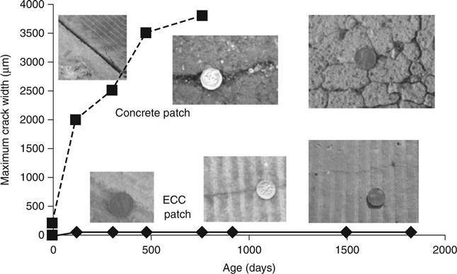
The performance of the ECC and adjacent concrete patch repairs was assessed through site visits. Initial visits 2 days after construction showed no visible cracking in the ECC patch repair. However, a clearly visible crack, about 300 μm wide, appeared in the concrete repair. A possible reason for the cracking was restrained shrinkage. After 4-months winter exposure, a number of microcracks with width around 50 μm had formed in the ECC patch repair. In contrast, the initial crack formed in the concrete repair widened to 2 mm and was surrounded by deteriorated and spalling concrete. In 2005, the concrete repair has severely deteriorated with cracks larger than 3.5 mm and had to be re-repaired. In 2007 when the complete bridge deck was reconstructed, the last available data point indicates that the ECC patch had survived the combined mechanical and environmental loading conditions with minor microcracking limited to less than 50 μm. No spalling or other deteriorations were found. The monitored crack width development is shown in Fig. 7.17. Field performance data revealed that ECC is a durable construction material in the harsh environments of Michigan winters in addition to heavy traffic loads.
7.4.2 High early strength ECC patch repair
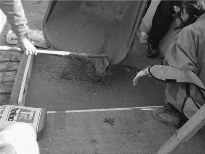
In November 2006, a patch repair made of a special version of ECC, HES-ECC, was constructed on the Ellsworth Road Bridge over US-23 (S07 of 81074) in Ann Arbor, Michigan.16,74 MDOT repair personnel conducted partial depth concrete removal, sandblasted the patch area, replaced damaged reinforcement, and completed patch preparation. Before pouring the patch materials, water fog was sprayed onto the concrete substrate to enhance repair bonding. The average temperature was 55°F (12.8°C) and relative humidity was 59.5% during this construction. 7 cubic feet (0.20 cubic meters) of HES-ECC was mixed using a 12 cubic foot (0.34 cubic meters) capacity concrete gas mixer provided by MDOT. The total mixing time was approximately 30 min. The fresh HES-ECC exhibited desirable viscosity, fiber distribution, and flowability. Flowability testing using a slump cone was conducted immediately after finishing the mixing and before repair placement. With a 25.6 in. (650.2 mm) slump diameter, the HES-ECC achieved a self-compacting state. The HES-ECC material was then poured into a wheelbarrow, transported to the patch area, and poured into the patch (Fig. 7.18). The self-compacting property of HES-ECC allowed it to easily flow into the corners of the patch area without any vibration. The surface of the HES-ECC patch repair was finalized by using a steel trowel, by hand.
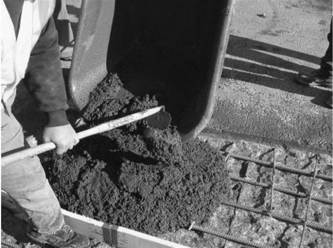
Mixing of Thoroc 10-60 (a patch repair material frequently used by MDOT) was performed using the same mixer. The fresh Thoroc 10-60 was barely flowable, resulting in much more effort and a longer time for construction workers to place and finish (Fig. 7.19). The two patch repairs using HES-ECC and Thoroc 10–60 are shown side by side in Fig. 7.20. Latex-based curing compound was sprayed onto both patches to reduce evaporation and shrinkage.

The two side-by-side patch repairs on the Ellsworth Road Bridge were completed at around 1 p.m. on Tuesday, 28 November 2006, as shown in Fig. 7.20. Taking advantage of the rapid strength gain of the materials, traffic reopened the next morning at 9 a.m.
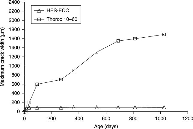
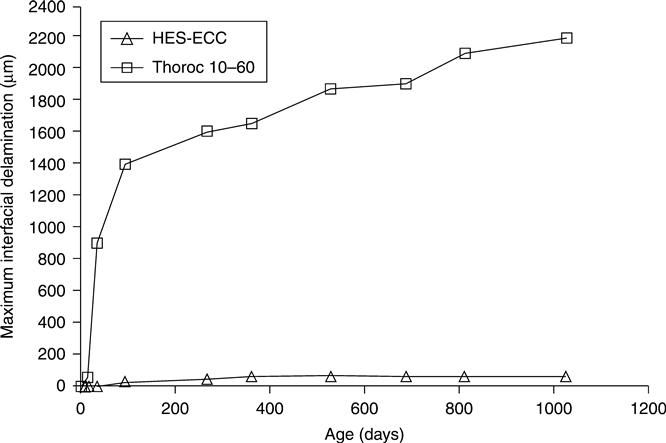
The performance of the HES-ECC and adjacent Thoroc 10-60 patch repairs has been assessed through a series of 12 site visits. This field performance data for 2 years and 10 months of patch life reveals the promise of HES-ECC as a durable repair material in the harsh environments of Michigan winters (with combined effects of restrained shrinkage, freezing and thawing, exposure to deicing salts, temperature change, etc.) in addition to heavy traffic loads, in terms of minimized surface cracking and old/new interfacial delamination (Figs 7.21 and 7.22).
7.4.3 ECC bridge link slab
Many highway bridges are composed of multiple span steel or prestressed concrete girders simply supported at piers or bents. The girders support cast-in-place concrete decks. A mechanical joint is typically used at the end of decks to allow deck deformation imposed by temperature variation, concrete shrinkage, and girder deflection. The bridge-deck joints are expensive to install and maintain. Debris accumulation can often cause deterioration of the expansion joints, which subsequently will lead to severe damage in the bridge deck and substructure. Thermal expansion caused by a high temperature combined with debris filled expansion joints can cause cracks or spalls near the expansion joints. Water leakage through the joints can cause beam-end corrosion, spalling, and deterioration of pier caps.
A possible approach to address this problem is the replacement of expansion joints by a concrete link slab in multi-span bridges. A link slab is a section of the deck that connects the two adjacent simple-span girders. A number of concrete link slabs have been constructed in other states, including Michigan and Florida, to address the continuing problem of deteriorating and leaking expansion joints (Fig. 7.23). In general, the link slabs are subjected to negative bending under traffic conditions and environmental loads, and tensile cracks may form at the top of the link slab.

To address these challenges, a high performance and durable link slab made of ECC was constructed in Michigan to replace expansion joints for multi-span simply supported bridges75 (Fig. 7.23). The ECC link slabs can maintain the simple-span performance of the bridge while accommodating mechanical and environmental (i.e. thermal) loads typically accounted for by the expansion joints. The ductile link slabs allow for a joint-free bridge deck, eliminating leaking problems while creating a smoother riding surface. Notably, the ECC slabs can accommodate large deformation with self-controlled microcrack width to far below the AASHTO limit, even without relying on steel reinforcement. In this way, the ECC link slab eliminates the tensile cracking problem at the top of conventional concrete link slabs. Furthermore, an integrated life cycle assessment and life cycle cost analysis (LCA-LCC) study showed that the bridge system incorporating ECC link slab consumed 40% less total primary energy, and 40% less carbon dioxide and other greenhouse gases, than the conventional bridge-deck system with expansion joints.76 Apparently, the long-term durability of ECC link slab leads to minimized maintenance and repairs, resulting in the significantly reduced economic and environmental impacts.
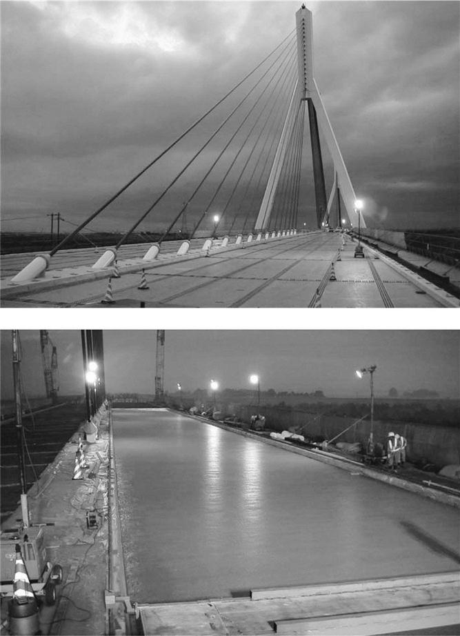
7.4.4 ECC steel composite bridge deck
A composite ECC/steel bridge deck was constructed in 2004 for a cable-stayed bridge (Mihara Bridge) in Hokkaido, Japan.77,78 The bridge, opened to traffic in 2005, is 1000 m long with the middle span of 340 m. The full deck area is 20 000 square meters (Fig. 7.24). The deck comprised a 38 mm thin layer of ECC placed on top of steel. This design took advantage of the high durability of ECC and its intrinsic crack control capacity, to protect the underlying steel from the penetration of moisture and chloride. This led to a super light-weight design with a 40% weight reduction, and thus a reduction of initial construction cost by 50%. With an expected service life of 100 years, the life cycle costs associated with maintenance, repair, and rehabilitation are also expected to be significantly lower than conventional bridge-deck systems.
7.5 Conclusions
ECC, by fundamentally eliminating concrete brittleness, has opened a new world of applications in bridge decks and other structures. This chapter described the field application of ECC in bridge-deck repairs, link slabs, and a new composite deck. The discussion on the properties of ECC under various mechanical and environmental loading conditions has provided insights on why the ductile behavior of ECC can lead to the durable and sustainable (i.e. low environmental impact) performance of ECC repair and new construction systems. ECC technology is still evolving, which includes the design of different versions of ECC materials, the creation of smart and multifunctional ECCs, the understanding of their behavior under combined mechanical and environmental conditions, the establishment of reliable ECC constitutive models under complex loading, and the development of ECC structural design specifications and codes for the wide application of this material in civil infrastructure.