Appendix D. Tables and Charts
The properties of materials vary widely depending on numerous factors, including chemical composition, manufacturing processes, internal defects, temperature, and dimensions of test specimens. Hence, the approximate values presented in Table D.1 are not necessarily suitable for specific application. Tabulated data are for reference in solving problems in the text. For details, see, for example, Refs. D.1 and D.2.
The International System of Units (SI) replaces the U.S. Customary Units, which have long been used by engineers in this country. The basic quantities in the two systems are as follows:
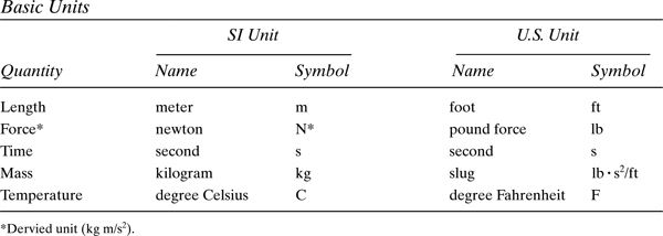
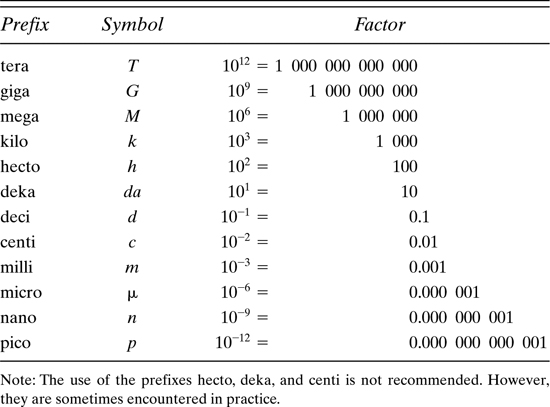
In the SI system, the acceleration due to gravity near Earth’s surface equals approximately 9.81 m/s2. A mass of 1 kilogram on Earth’s surface will experience a gravitational force of 9.81 N. Thus, a mass of 1 kg has, owing to the gravitational force of Earth, a weight of 9.81 N. Interestingly, one newton is approximately the weight of (or Earth’s gravitional force on) an average apple. Tables D.2 and D.3 contain conversion factors and SI unit prefixes in common usage.
Table D.1. Average Properties of Common Engineering Materialsa (SI Units)
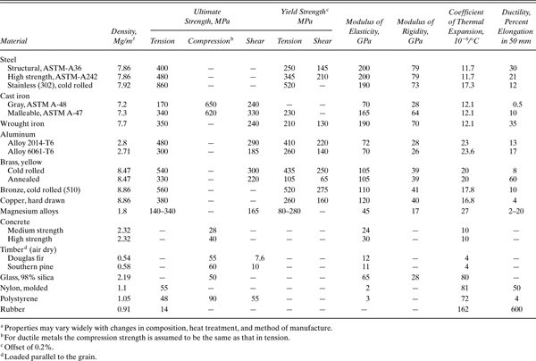
Table D.1. Average Properties of Common Engineering Materialsa (U.S. Customary Units)
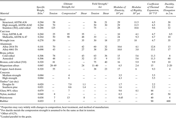
Table D.2. Conversion Factors: SI Units to U.S. Customary Units

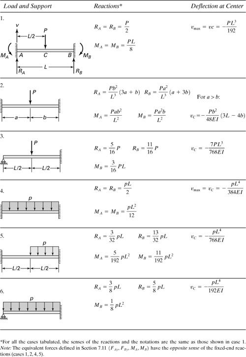
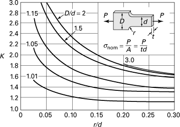
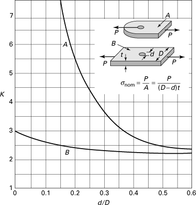
The expressions for deflection and slope for selected members given in Tables D.4 and D.5 are representative of results found in a number of handbooks [Ref. D.3]. Restrictions on the application of these formulas include constancy of the flexural rigidity EI, symmetry of the cross section about the vertical y axis, and the magnitude of displacement v of the beam. In addition, the expressions apply to beams long in proportion to their depth and not disproportionally wide (see Secs. 5.4 and 5.6). The stress concentration factors K (Figures D.1 through D.8) were selected from extensive charts found in Refs. D.4 and D.5.
Table D.4. Deflections and Slopes of Beams
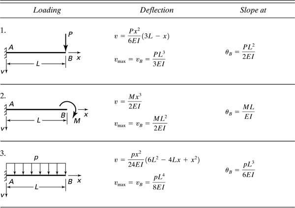

Table D.5. Reactions Deflections of Statically Indeterminate Beams
D.6 Stress Concentration Factors for Bars and Shafts with Fillets, Grooves, and Holes
Figure D.1. Stress concentration factor K for a filleted bar in axial tension.
Approximate formula ![]() , where:
, where:
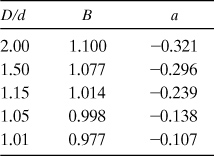
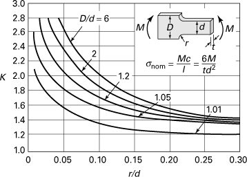
Figure D.2. Stress concentration factor K for a filleted bar in bending.
Approximate formula ![]() , where:
, where:
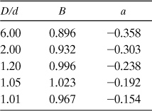
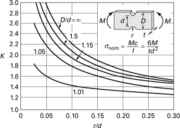
Figure D.3. Stress concentration factor K for a notched bar in bending.
Approximate formula ![]() , where:
, where:

Figure D.4. Stress concentration factor K for a shaft with a shoulder fillet in torsion.
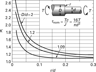
Approximate formula ![]() , where:
, where:

Figure D.5. Stress concentration factor K for a grooved shaft in axial tension.
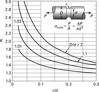
Figure D.6. Stress concentration factor K for a grooved shaft in torsion.
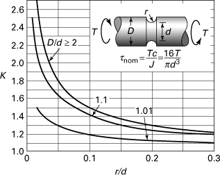
Approximate formula ![]() , where:
, where:
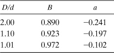
Figure D.7. Stress concentration factor K for a grooved shaft in bending.
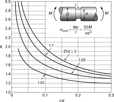
Approximate formula ![]() , where:
, where:

Figure D.8. Stress concentration factor K; A—for a flat bar loaded in tension by a pin through the transverse hole; B—for a flat bar with a transverse hole in axial tension.
References
D.1. AVALLONE, E. A., and BAUMEISTER III, T., eds., Mark’s Standard Handbook for Mechanical Engineers, 10th ed., McGraw-Hill, New York, 1997.
D.2. American Society of Testing and Materials, Annual Book of ASTM, Philadelphia, Pa.
D.3. YOUNG, W. C., Roark’s Formulas for Stress and Strain, 6th ed., McGraw-Hill, New York, 1989, Chap. 7.
D.4. PETERSON, R. E., Stress Concentration Factors, Wiley, Hoboken, N. J., 1974.
D.5. UGURAL, A. C., Mechanical Design: An Integrated Approach, McGraw-Hill, New York, 2004.