Chapter 8. Physical Output
8.0. Introduction
You can make things move by controlling motors with Arduino. Different types of motors suit different applications, and this chapter shows how Arduino can drive many different kinds of motors.
Motion Control Using Servos
Servos enable you to accurately control physical movement because they generally move to a position instead of continuously rotating. They are ideal for making something rotate over a range of 0 to 180 degrees. Servos are easy to connect and control because the motor driver is built into the servo.
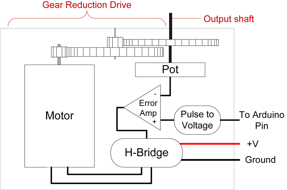
Servos contain a small motor connected through gears to an output shaft. The output shaft drives a servo arm and is also connected to a potentiometer to provide position feedback to an internal control circuit (see Figure 8-1).
You can get continuous rotation servos that have the positional
feedback disconnected so that you can instruct the servo to rotate
continuously clockwise and counterclockwise with some control over the
speed. These function a little like the brushed motors covered in
Recipe 8.9, except that
continuous rotation servos use the servo library code instead of
analogWrite and don’t require a
motor shield.
Continuous rotation servos are easy to use because they don’t need a motor shield—the motor drivers are inside the servo. The disadvantages are that the speed and power choices are limited compared to external motors, and the precision of speed control is usually not as good as with a motor shield (the electronics is designed for accurate positioning, not linear speed control). See Recipe 8.3 for more on using continuous rotation servos.
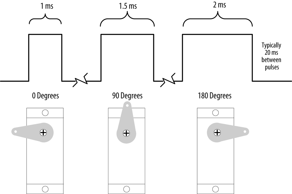
Servos respond to changes in the duration of a pulse. A short pulse of 1 ms or less will cause the servo to rotate to one extreme; a pulse duration of 2 ms or so will rotate the servo to the other extreme (see Figure 8-2). Pulses ranging between these values will rotate the servo to a position proportional to the pulse width. There is no standard for the exact relationship between pulses and position, and you may need to tinker with the commands in your sketch to adjust for the range of your servos.
Warning
Although the duration of the pulse is
modulated (controlled), servos require pulses
that are different from the Pulse Width Modulation (PWM) output from
analogWrite. You can damage a
hobby servo by connecting it to the output from analogWrite—use the Servo library
instead.
Solenoids and Relays
Although most motors produce rotary motion, a solenoid produces linear movement when powered. A solenoid has a metallic core that is moved by a magnetic field created when current is passed through a coil. A mechanical relay is a type of solenoid that connects or disconnects electrical contacts (it’s a solenoid operating a switch). Relays are controlled just like solenoids. Relays and solenoids, like most motors, require more current than an Arduino pin can safely provide, and the recipes in this chapter show how you can use a transistor or external circuit to drive these devices.
Brushed and Brushless Motors
Most low-cost direct current (DC) motors are simple devices with two leads connected to brushes (contacts) that control the magnetic field of the coils that drives a metallic core (armature). The direction of rotation can be reversed by reversing the polarity of the voltage on the contacts. DC motors are available in many different sizes, but even the smallest (such as vibration motors used in cell phones) require a transistor or other external control to provide adequate current. The recipes that follow show how to control motors using a transistor or an external control circuit called an H-Bridge.
The primary characteristic in selecting a motor is torque. Torque determines how much work the motor can do. Typically, higher torque motors are larger and heavier and draw more current than lower torque motors.
Brushless motors usually are more powerful and efficient for a given size than brushed motors, but they require more complicated electronic control. Where the performance benefit of a brushless motor is desired, components called electronics speed controllers intended for hobby radio control use can be easily controlled by Arduino because they are controlled much like a servo motor.
Stepper Motors
Steppers are motors that rotate a specific number of degrees in response to control pulses. The number of degrees in each step is motor-dependent, ranging from one or two degrees per step to 30 degrees or more.
Two types of steppers are commonly used with Arduino: bipolar (typically with four leads attached to two coils) and unipolar (five or six leads attached to two coils). The additional wires in a unipolar stepper are internally connected to the center of the coils (in the five-lead version, each coil has a center tap and both center taps are connected together). The recipes covering bipolar and unipolar steppers have diagrams illustrating these connections.
8.1. Controlling the Position of a Servo
Problem
You want to control the position of a servo using an angle calculated in your sketch. For example, you want a sensor on a robot to swing through an arc or move to a position you select.
Solution
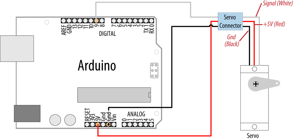
Use the Servo library distributed with Arduino. Connect the servo power and ground to a suitable power supply (a single hobby servo can usually be powered from the Arduino 5V line). Recent versions of the library enable you to connect the servo signal leads to any Arduino digital pin.
Here is the example Sweep sketch distributed with Arduino; Figure 8-3 shows the connections:
#include <Servo.h>

Servo myservo;  // create servo object to control a servo

int angle = 0;    // variable to store the servo position

void setup()
{
  myservo.attach(9);  // attaches the servo on pin 9 to the servo object
}


void loop()
{
  for(angle = 0; angle < 180; angle += 1)  // goes from 0 degrees to 180 degrees
  {                                        // in steps of 1 degree
    myservo.write(angle);    // tell servo to go to position in variable 'angle'
    delay(20);               // waits 20ms between servo commands
  }
  for(angle = 180; angle >= 1; angle -= 1) // goes from 180 degrees to 0 degrees
  {
    myservo.write(angle);   // move servo in opposite direction
    delay(20);              // waits 20ms between servo commands
  }
}
Discussion
This example sweeps the servo between 0 and 180 degrees. You may
need to tell the library to adjust the minimum and maximum positions
so that you get the range of movement you want. Calling Servo.attach with
optional arguments for minimum and maximum positions will adjust the
movement:
myservo.attach(9,1000,2000 ); // use pin 9, set min to 1000us, max to 2000us
Because typical servos respond to pulses measured in microseconds and not degrees, the arguments following the pin number inform the Servo library how many microseconds to use when 0 degrees or 180 degrees are requested. Not all servos will move over a full 180-degree range, so you may need to experiment with yours to get the range you want.
The parameters for servo.attach(pin, min, max) are the following:
pinThe pin number that the servo is attached to (you can use any digital pin)
min(optional)The pulse width, in microseconds, corresponding to the minimum (0-degree) angle on the servo (defaults to 544)
max(optional)The pulse width, in microseconds, corresponding to the maximum (180-degree) angle on the servo (defaults to 2,400)
Note
The Servo library supports up to 12 servos on most Arduino
boards and 48 on the Arduino Mega. On standard boards such as the
Uno, use of the library disables analogWrite() (PWM) functionality on pins
9 and 10, whether or not there is a servo on those pins. See the
Servo library reference for more information: http://arduino.cc/en/Reference/Servo.
Power requirements vary depending on the servo and how much torque is needed to rotate the shaft.
Note
You may need an external source of 5 or 6 volts when connecting multiple servos. Four AA cells work well if you want to use battery power. Remember that you must connect the ground of the external power source to Arduino ground.
8.2. Controlling One or Two Servos with a Potentiometer or Sensor
Problem
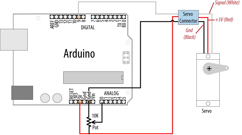
You want to control the rotational direction and speed of one or two servos with a potentiometer. For example, you want to control the pan and tilt of a camera or sensor connected to the servos. This recipe can work with any variable voltage from a sensor that can be read from an analog input.
Solution
The same library can be used as in Recipe 8.1, with the addition of
code to read the voltage on a potentiometer. This value is scaled so
that the position of the pot (from 0 to 1023) is mapped to a range of 0 to 180
degrees. The only difference in the wiring is the addition of the
potentiometer; see Figure 8-4:
#include <Servo.h>

Servo myservo;  // create servo object to control a servo

int potpin = 0;  // analog pin used to connect the potentiometer
int val;    // variable to read the value from the analog pin

void setup()
{
  myservo.attach(9);  // attaches the servo on pin 9 to the servo object
}

void loop()
{
  val = analogRead(potpin);            // reads the value of the potentiometer
  val = map(val, 0, 1023, 0, 180);     // scale it to use it with the servo
  myservo.write(val);                  // sets position to the scaled value
  delay(15);                           // waits for the servo to get there
}
Note
Hobby servos have a cable with a 3-pin female connector that can be directly plugged in to a “servo” header fitted to some shields, such as the Adafruit Motor Shield. The physical connector is compatible with the Arduino connectors so you can use the same wire jumpers to those used to connect Arduino pins. Bear in mind that the color of the signal lead is not standardized; yellow is sometimes used instead of white. Red is always in the middle and the ground lead is usually black or brown.
Discussion
Anything that can be read from analogRead (see
Chapter 5 and Chapter 6) can be used—for example, the gyro and
accelerometer recipes in Chapter 6
can be used, so that the angle of the servo is controlled by the yaw
of the gyro or angle of the accelerometer.
Note
Not all servos will rotate over the full range of the Servo library. If your servo buzzes due to hitting an end stop at an extreme of movement, try reducing the output range in the map function until the buzzing stops. For example:
val=map(val,0,1023,10,170); // most
          function over this range
8.3. Controlling the Speed of Continuous Rotation Servos
Problem
You want to control the rotational direction and speed of servos modified for continuous rotation. For example, you are using two continuous rotation servos to power a robot and you want the speed and direction to be controlled by your sketch.
Solution
Continuous rotation servos are a form of gear-reduced motor with forward and backward speed adjustment. Control of continuous rotation servos is similar to normal servos. The servo rotates in one direction as the angle is increased from 90 degrees; it rotates in the other direction when the angle is decreased from 90 degrees. The actual direction forward or backward depends on how you have the servos attached. Figure 8-5 shows the connections for controlling two servos.
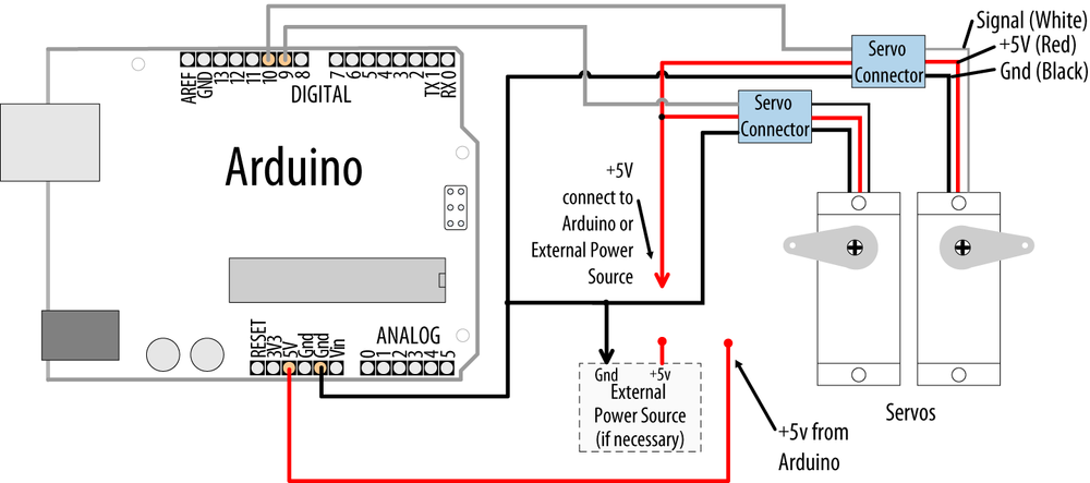
Servos are usually powered from a 4.8V to 6V source. Heavier duty servos may require more current than the Arduino board can provide through the +5V pin and these will require an external power source. Four 1.2V rechargeable batteries can be used to power Arduino and the servos. Bear in mind that fresh alkaline cells can have a voltage higher than 1.5 volts, so if using alkaline batteries, check with your multimeter that the total voltage does not exceed 6 volts—the absolute maximum operating voltage for Arduino chips.
The sketch sweeps the servos from 90 to 180 degrees, so if the
servos were connected to wheels, the vehicle would move forward at a
slowly increasing pace and then slow down to a stop. Because the servo
control code is in loop, this will
continue for as long as there is power:
#include <Servo.h>

Servo myservoLeft;   // create servo object to control a servo
Servo myservoRight;  // create servo object to control a servo

int angle = 0;    // variable to store the servo position

void setup()
{
  myservoLeft.attach(9);   // attaches left servo on pin 9 to servo object
  myservoRight.attach(10); // attaches right servo on pin 10 to servo object
}

void loop()
{
  for(angle = 90; angle < 180; angle += 1)  // goes from 90 to 180 degrees
  {                                         // in steps of 1 degree.
                                            // 90  degrees is stopped.

    myservoLeft.write(angle);        // rotate servo at speed given by 'angle'
    myservoRight.write(180-angle);   // go in the opposite direction

    delay(20);                       // waits 20ms between servo commands
  }
  for(angle = 180; angle >= 90; angle -= 1) // goes from 180 to 90 degrees
  {
    myservoLeft.write(angle);        // rotate at a speed given by 'angle'
    myservoRight.write(180-angle);   // other servo goes in opposite direction
  }
}
Discussion
You can use similar code for continuous rotation and normal servos, but be aware that continuous rotation servos may not stop rotating when writing exactly 90 degrees. Some servos have a small potentiometer you can trim to adjust for this, or you can add or subtract a few degrees to stop the servo. For example, if the left servo stops rotating at 92 degrees, you can change the lines that write to the servos as follows:
myservoLeft.write(angle+TRIM); // declare int TRIM=2; at beginning of sketch
8.4. Controlling Servos Using Computer Commands
Problem
You want to provide commands to control servos from the serial port. Perhaps you want to control servos from a program running on your computer.
Solution
You can use software to control the servos. This has the advantage that any number of servos can be supported. However, your sketch needs to constantly attend to refreshing the servo position, so the logic can get complicated as the number of servos increases if your project needs to perform a lot of other tasks.
This recipe drives four servos according to commands received on the serial port. The commands are of the following form:
180awrites 180 to servo a90bwrites 90 to servo b0cwrites 0 to servo c17dwrites 17 to servo d
Here is the sketch that drives four servos connected on pins 7 through 10:
#include <Servo.h>  // the servo library

#define SERVOS 4 // the number of servos
int servoPins[SERVOS] = {7,8,9,10}; // servos on pins 7 through 10

Servo myservo[SERVOS];

void setup()
{
  Serial.begin(9600);
  for(int i=0; i < SERVOS; i++)
    myservo[i].attach(servoPins[i]);
}

void loop()
{
  serviceSerial();
}

// serviceSerial checks the serial port and updates position with received data
// it expects servo data in the form:
//
//  "180a" writes 180 to servo a
//  "90b writes 90 to servo b
//
void serviceSerial()
{
  static int pos = 0;

  if ( Serial.available()) {
    char ch = Serial.read();

    if( isDigit(ch) )                       // If ch is a number:
      pos = pos * 10 + ch - '0';            // accumulate the value
    else if(ch >= 'a' && ch <= 'a'+ SERVOS) // If ch is a letter for our servos:
      myservo[ch - 'a'].write(pos);         // save the position in position array
  }
}
Discussion
Connecting the servos is similar to the previous recipes. Each servo line wire gets connected to a digital pin. All servo grounds are connected to Arduino ground. The servo power lines are connected together, and you may need an external 5V or 6V power source if your servos require more current than the Arduino power supply can provide.
An array named myservo (see
Recipe 2.4) is used to hold
references for the four servos. A for loop in setup attaches each servo in the array to
consecutive pins defined in the servoPins array.
If the character received from serial is a digit (the character
will be greater than or equal to 0 and less than or equal to 9), its
value is accumulated in the variable pos. If the character is the letter
a, the position is written to the first servo in
the array (the servo connected to pin 7). The letters
b, c, and
d control the subsequent servos.
See Also
See Chapter 4 for more on handling values received over serial.
8.5. Driving a Brushless Motor (Using a Hobby Speed Controller)
Solution
This sketch uses the same code as Recipe 8.2. The wiring is similar, except for the speed controller and motor. A hobby electronic speed controller (ESC) is a device used to control brushless motors in radio-controlled vehicles. Because these items are mass produced, they are a cost-effective way to drive brushless motors. You can find a selection by typing “esc” into the search field of your favorite hobby store website or typing “speed controller esc” into Google.
Brushless motors have three windings and these should be connected following the instructions for your speed controller (see Figure 8-6).
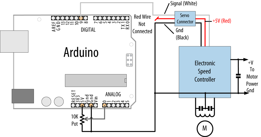
Discussion
Consult the documentation for your speed controller to confirm that it is suitable for your brushless motor and to verify the wiring. Brushless motors have three connections for the three motor wires and two connections for power. Many speed controllers provide power on the center pin of the servo connector. Unless you want to power the Arduino board from the speed controller, you must disconnect or cut this center wire.
Warning
If your speed controller has a feature that provides 5V power to servos and other devices (called a battery eliminator circuit or BEC for short), you must disconnect this wire when attaching the Arduino to the speed controller (see Figure 8-6).
8.6. Controlling Solenoids and Relays
Problem
You want to activate a solenoid or relay under program control. Solenoids are electromagnets that convert electrical energy into mechanical movement. An electromagnetic relay is a switch that is activated by a solenoid.
Solution
Most solenoids require more power than an Arduino pin can
provide, so a transistor is used to switch the current needed to
activate a solenoid. Activating the solenoid is achieved by
using digitalWrite to set
the pin HIGH.
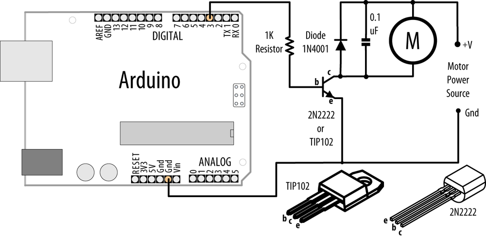
This sketch turns on a transistor connected as shown in Figure 8-7. The solenoid will be activated for one second every hour:
int solenoidPin = 2;            // Solenoid connected to transistor on pin 2

void setup()
{
  pinMode(solenoidPin, OUTPUT);
}

void loop()
{
  long interval = 1000 * 60 * 60 ;   // interval = 60 minutes

  digitalWrite(solenoidPin, HIGH); // activates the solenoid
  delay(1000);                     // waits for a second
  digitalWrite(solenoidPin, LOW);  // deactivates the solenoid
  delay(interval);                 // waits one hour
}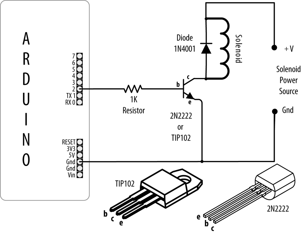
Discussion
The choice of transistor is dependent on the amount of current required to activate the solenoid or relay. The data sheet may specify this in milliamperes (mA) or as the resistance of the coil. To find the current needed by your solenoid or relay, divide the voltage of the coil by its resistance in ohms. For example, a 12V relay with a coil of 185 ohms draws 65 mA: 12 (volts) / 185 (ohms) = 0.065 amps, which is 65 mA.
Small transistors such as the 2N2222 are sufficient for solenoids requiring up to a few hundred milliamps. Larger solenoids will require a higher power transistor, like the TIP102/TIP120 or similar. There are many suitable transistor alternatives; see Appendix B for help reading a data sheet and choosing transistors.
The purpose of the diode is to prevent reverse EMF from the coil from damaging the transistor (reverse EMF is a voltage produced when current through a coil is switched off). The polarity of the diode is important; there is a colored band indicating the cathode—this should be connected to the solenoid positive power supply.
Electromagnetic relays are activated just like solenoids. A special relay called a solid state relay (SSR) has internal electronics that can be driven directly from an Arduino pin without the need for the transistor. Check the data sheet for your relay to see what voltage and current it requires; anything more than 40 mA at 5 volts will require a circuit such as the one shown in Figure 8-7.
8.7. Making an Object Vibrate
Problem
You want something to vibrate under Arduino control. For example, you want your project to shake for one second every minute.
Solution
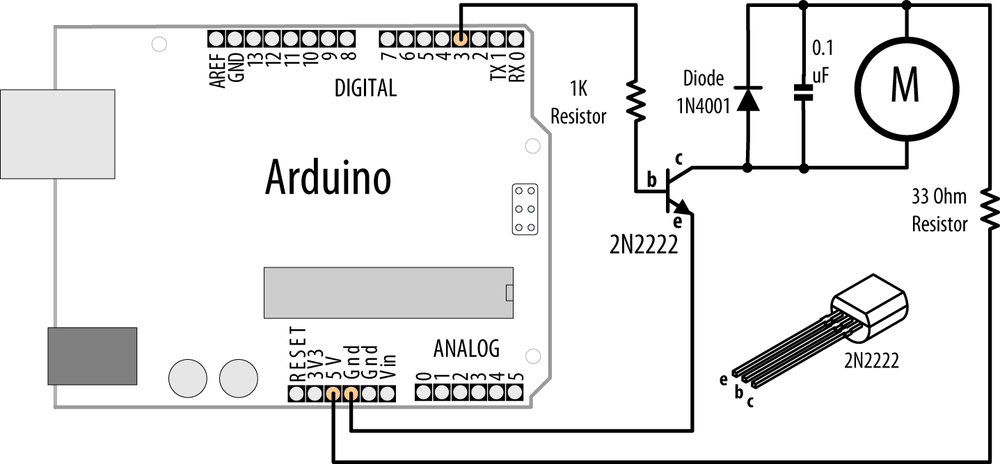
Connect a vibration motor as shown in Figure 8-8.
The following sketch will turn on the vibration motor for one second each minute:
/*
 * Vibrate sketch
 * Vibrate for one second every minute
 *
 */

const int motorPin  = 3;  // vibration motor transistor is connected to pin 3

void setup()
{
  pinMode(motorPin, OUTPUT);
}

void loop()
{
  digitalWrite(motorPin,  HIGH);  // vibrate
  delay(1000); // delay one second
  digitalWrite(motorPin,  LOW);   // stop vibrating
  delay(59000); // wait 59 seconds.
}
Discussion
This recipe uses a motor designed to vibrate, such as the SparkFun ROB-08449. If you have an old cell phone you no longer need, it may contain tiny vibration motors that would be suitable. Vibration motors require more power than an Arduino pin can provide, so a transistor is used to switch the motor current on and off. Almost any NPN transistor can be used; Figure 8-3 shows the common 2N2222. See this book’s website for supplier information on this and the other components used. A 1 kilohm resistor connects the output pin to the transistor base; the value is not critical, and you can use values up to 4.7 kilohm or so (the resistor prevents too much current flowing through the output pin). The diode absorbs (or snubs—it’s sometimes called a snubber diode) voltages produced by the motor windings as it rotates. The capacitor absorbs voltage spikes produced when the brushes (contacts connecting electric current to the motor windings) open and close. The 33 ohm resistor is needed to limit the amount of current flowing through the motor.
This sketch sets the output pin HIGH for one second (1,000 milliseconds) and
then waits for 59 seconds. The transistor will turn on (conduct) when
the pin is HIGH, allowing current
to flow through the motor.
Here is a variation of this sketch that uses a sensor to make the motor vibrate. The wiring is similar to that shown in Figure 8-8, with the addition of a photocell connected to analog pin 0 (see Recipe 6.2):
/*
 * Vibrate_Photocell sketch
 * Vibrate when photosensor detects light above ambient level
 *
 */

const int motorPin  = 3;  // vibration motor transistor is connected to pin 3
const int sensorPin = 0;  // Photodetector connected to analog input 0
int sensorAmbient = 0;             // ambient light level (calibrated in setup)
const int thresholdMargin = 100;   // how much above ambient needed to vibrate

void setup()
{
  pinMode(motorPin, OUTPUT);
  sensorAmbient = analogRead(sensorPin); // get startup light level;
}

void loop()
{
  int sensorValue = analogRead(sensorPin);
  if( sensorValue > sensorAmbient + thresholdMargin)
  {
      digitalWrite(motorPin,  HIGH); //vibrate
  }
  else
   {
      digitalWrite(motorPin,  LOW);   // stop vibrating
  }
}
Here the output pin is turned on when a light shines on the
photocell. When the sketch starts, the background light level on the
sensor is read and stored in the variable sensorAmbient. Light levels read in loop that are higher than this will turn on
the vibration motor.
8.8. Driving a Brushed Motor Using a Transistor
Problem
You want to turn a motor on and off. You may want to control its speed. The motor only needs to turn in one direction.
Solution
This sketch turns the motor on and off and controls its speed from commands received on the serial port (Figure 8-9 shows the connections):
/*
 * SimpleBrushed sketch
 * commands from serial port control motor speed
 * digits '0' through '9' are valid where '0' is off, '9' is max speed
 */

const int motorPin = 3; // motor driver is connected to pin 3

void setup()
{
  Serial.begin(9600);
}

void loop()
{
  if ( Serial.available()) {
    char ch = Serial.read();

    if(isDigit(ch))              // is ch a number?
    {
      int speed = map(ch, '0', '9', 0, 255);
      analogWrite(motorPin, speed);
      Serial.println(speed);
    }
    else
    {
      Serial.print("Unexpected character ");
      Serial.println(ch);
    }
  }
}
Discussion
This recipe is similar to Recipe 8.7; the difference is that analogWrite is used to control the speed of
the motor. See Analog Output for more on analogWrite and Pulse Width Modulation
(PWM).
8.9. Controlling the Direction of a Brushed Motor with an H-Bridge
Problem
You want to control the direction of a brushed motor—for example, you want to cause a motor to rotate in one direction or the other from serial port commands.
Solution
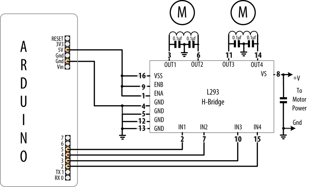
An H-Bridge can control two brushed motors. Figure 8-10 shows the connections for the L293D H-Bridge IC; you can also use the SN754410, which has the same pin layout:
/*
 * Brushed_H_Bridge_simple sketch
 * commands from serial port control motor direction
 * + or - set the direction, any other key stops the motor
 */

const int in1Pin = 5;  // H-Bridge input pins
const int in2Pin = 4;

void setup()
{
  Serial.begin(9600);
  pinMode(in1Pin, OUTPUT);
  pinMode(in2Pin, OUTPUT);
  Serial.println("+ - to set direction, any other key stops motor");
}void loop()
{
  if ( Serial.available()) {
    char ch = Serial.read();
    if (ch == '+')
    {
      Serial.println("CW");
      digitalWrite(in1Pin,LOW);
      digitalWrite(in2Pin,HIGH);
    }
    else if (ch == '-')
    {
      Serial.println("CCW");
      digitalWrite(in1Pin,HIGH);
      digitalWrite(in2Pin,LOW);
    }
    else
    {
      Serial.print("Stop motor");
      digitalWrite(in1Pin,LOW);
      digitalWrite(in2Pin,LOW);
    }
  }
}
Discussion
Table 8-1 shows how the values
on the H-Bridge input affect the motor. In the sketch in this recipe’s
Solution, a single motor is controlled using the IN1 and IN2 pins; the
EN pin is permanently HIGH because
it is connected to +5V.
EN | IN1 | IN2 | Function |
| | | Turn clockwise |
| | | Turn counterclockwise |
| | | Motor stop |
| | | Motor stop |
| Ignored | Ignored | Motor stop |
Figure 8-10 shows how a second motor can be connected. The following sketch controls both motors together:
/*
 * Brushed_H_Bridge_simple2 sketch
 * commands from serial port control motor direction
 * + or - set the direction, any other key stops the motors
 */

const int in1Pin = 5;  // H-Bridge input pins
const int in2Pin = 4;

const int in3Pin = 3;  // H-Bridge pins for second motor
const int in4Pin = 2;

void setup()
{
  Serial.begin(9600);
  pinMode(in1Pin, OUTPUT);
  pinMode(in2Pin, OUTPUT);
  pinMode(in3Pin, OUTPUT);
  pinMode(in4Pin, OUTPUT);
  Serial.println("+ - sets direction of motors, any other key stops motors");
}

void loop()
{
  if ( Serial.available()) {
    char ch = Serial.read();
    if (ch == '+')    {
      Serial.println("CW");
      // first motor
      digitalWrite(in1Pin,LOW);
      digitalWrite(in2Pin,HIGH);
      //second motor
      digitalWrite(in3Pin,LOW);
      digitalWrite(in4Pin,HIGH);
    }
    else if (ch == '-')
    {
      Serial.println("CCW");
      digitalWrite(in1Pin,HIGH);
      digitalWrite(in2Pin,LOW);

      digitalWrite(in3Pin,HIGH);
      digitalWrite(in4Pin,LOW);
    }
    else
    {
      Serial.print("Stop motors");
      digitalWrite(in1Pin,LOW);
      digitalWrite(in2Pin,LOW);
      digitalWrite(in3Pin,LOW);
      digitalWrite(in4Pin,LOW);
    }
  }
}
8.10. Controlling the Direction and Speed of a Brushed Motor with an H-Bridge
Problem
You want to control the direction and speed of a brushed motor. This extends the functionality of Recipe 8.9 by controlling both motor direction and speed through commands from the serial port.
Solution
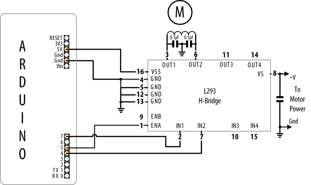
Connect a brushed motor to the output pins of the H-Bridge as shown in Figure 8-11.
This sketch uses commands from the Serial Monitor to control the speed and direction of the motor. Sending 0 will stop the motor, and the digits 1 through 9 will control the speed. Sending “+” and “-” will set the motor direction:
/*
 * Brushed_H_Bridge sketch
 * commands from serial port control motor speed and direction
 * digits '0' through '9' are valid where '0' is off, '9' is max speed
 * + or - set the direction
 */

const int enPin  = 5;  // H-Bridge enable pin
const int in1Pin = 7;  // H-Bridge input pins
const int in2Pin = 4;

void setup()
{
  Serial.begin(9600);
  pinMode(in1Pin, OUTPUT);
  pinMode(in2Pin, OUTPUT);
  Serial.println("Speed (0-9) or + - to set direction");
}

void loop()
{
  if ( Serial.available()) {
    char ch = Serial.read();    if(isDigit(ch))              // is ch a number?
    {
      int speed = map(ch, '0', '9', 0, 255);
      analogWrite(enPin, speed);
      Serial.println(speed);
    }
    else if (ch == '+')
    {
      Serial.println("CW");
      digitalWrite(in1Pin,LOW);
      digitalWrite(in2Pin,HIGH);
    }
    else if (ch == '-')
    {
      Serial.println("CCW");
      digitalWrite(in1Pin,HIGH);
      digitalWrite(in2Pin,LOW);
    }
    else
    {
      Serial.print("Unexpected character ");
      Serial.println(ch);
    }
  }
}
Discussion
This recipe is similar to Recipe 8.9, in which motor
direction is controlled by the levels on the IN1 and IN2 pins. But in
addition, speed is controlled by the analogWrite value on
the EN pin (see Chapter 7 for more on PWM).
Writing a value of 0 will stop the
motor; writing 255 will run the
motor at full speed. The motor speed will vary in proportion to values
within this range.
8.11. Using Sensors to Control the Direction and Speed of Brushed Motors (L293 H-Bridge)
Problem
You want to control the direction and speed of brushed motors with feedback from sensors. For example, you want two photo sensors to control motor speed and direction to cause a robot to move toward a beam of light.
Solution
This Solution uses similar motor connections to those shown in Figure 8-10, but with the addition of two light-dependent resistors, as shown in Figure 8-12.
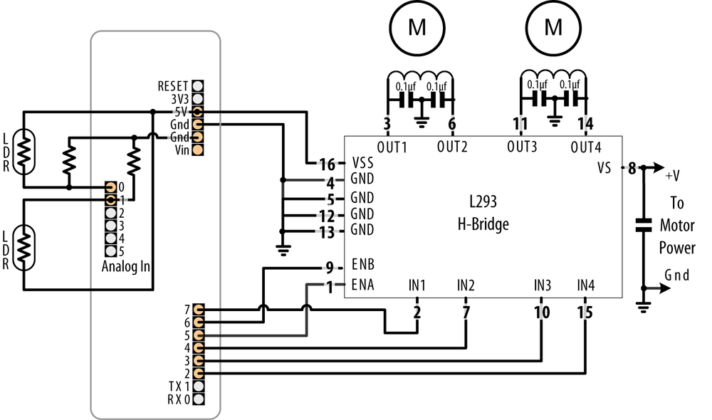
The sketch monitors the light level on the sensors and drives the motors to steer toward the sensor detecting the brighter light level:
/*
 * Brushed_H_Bridge_Direction sketch
 * uses photo sensors to control motor direction
 * robot moves in the direction of a light
 */

 int leftPins[]  = {5,7,4};  // on pin for PWM, two pins for motor direction
 int rightPins[] = {6,3,2};

const int MIN_PWM        = 64;  // this can range from 0 to MAX_PWM;
const int MAX_PWM        = 128; // this can range from around 50 to 255;
const int leftSensorPin = 0;  // analog pins with sensors
const int rightSensorPin = 1;

int sensorThreshold = 0;      // must have this much light on a sensor to move

void setup()
{
  for(int i=1; i < 3; i++)
  {
    pinMode(leftPins[i], OUTPUT);
    pinMode(rightPins[i], OUTPUT);
  }
}

void loop()
{
  int leftVal = analogRead(leftSensorPin);
  int rightVal = analogRead(rightSensorPin);

  if(sensorThreshold == 0){  // have the sensors been calibrated ?
  // if not, calibrate sensors to something above the ambient average
     sensorThreshold = ((leftVal + rightVal) / 2) + 100 ;
  }

  if( leftVal > sensorThreshold || rightVal > sensorThreshold)
  {
    // if there is adequate light to move ahead
    setSpeed(rightPins, map(rightVal,0,1023, MIN_PWM, MAX_PWM));
    setSpeed(leftPins,  map(leftVal ,0,1023, MIN_PWM, MAX_PWM));
  }
}

void setSpeed(int pins[], int speed )
{
  if(speed < 0)
  {
    digitalWrite(pins[1],HIGH);
    digitalWrite(pins[2],LOW);
    speed = -speed;
  }
  else
  {
    digitalWrite(pins[1],LOW);
    digitalWrite(pins[2],HIGH);
  }
  analogWrite(pins[0], speed);
}
Discussion
This sketch controls the speed of two motors in response to the amount of light detected by two photocells. The photocells are arranged so that an increase in light on one side will increase the speed of the motor on the other side. This causes the robot to turn toward the side with the brighter light. Light shining equally on both cells makes the robot move forward in a straight line. Insufficient light causes the robot to stop.
Light is sensed through analog inputs 0 and 1 using analogRead (see Recipe 6.2). When the program starts, the ambient
light is measured and this threshold is used to determine the minimum
light level needed to move the robot. A margin of 100 is added to the
average level of the two sensors so the robot won’t move for small
changes in ambient light level. Light level as measured with analogRead is converted into a PWM value
using the map function. Set
MIN_PWM to the approximate value
that enables your robot to move (low values will not provide
sufficient torque; find this through trial and error with your robot).
Set MAX_PWM to a value (up to 255)
to determine the fastest speed you want the robot to move.
Motor speed is controlled in the setSpeed function.
Two pins are used to control the direction for each motor, with
another pin to control speed. The pin numbers are held in the leftPins and rightPins arrays. The first pin in each
array is the speed pin; the other two pins are for direction.
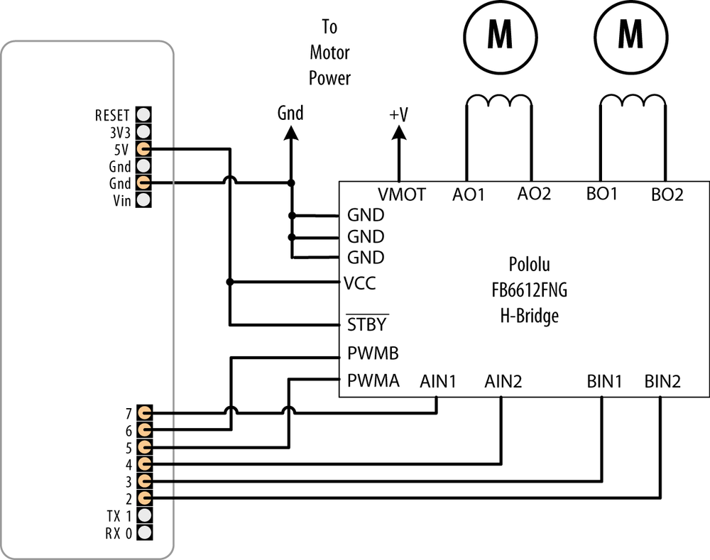
An alternative to the L293 is the Toshiba FB6612FNG. This can be used in any of the recipes showing the L293D. Figure 8-13 shows the wiring for the FB6612 as used on the Pololu breakout board (SparkFun ROB-09402).
You can reduce the number of pins needed by adding additional hardware to control the direction pins. This is done by using only one pin per motor for direction, with a transistor or logic gate to invert the level on the other H-Bridge input. You can find circuit diagrams for this in the Arduino wiki, but if you want something already wired up, you can use an H-Bridge shield such as the Freeduino motor control shield (NKC Electronics ARD-0015) or the Ardumoto from SparkFun (DEV-09213). These shields plug directly into Arduino and only require connections to the motor power supply and windings.
Here is the sketch revised for the Ardumoto shield:
/*
 * Brushed_H_Bridge_Direction sketch for Ardumotor shield
 * uses photo sensors to control motor direction
 * robot moves in the direction of a light
 */

 int leftPins[]  = {10,12};   // one pin for PWM, one pin for motor direction
 int rightPins[] = {11,13};

const int MIN_PWM        = 64;  // this can range from 0 to MAX_PWM;
const int MAX_PWM        = 128; // this can range from around 50 to 255;
const int leftSensorPin = 0;  // analog pins with sensors
const int rightSensorPin = 1;

int sensorThreshold = 0;      // must have this much light on a sensor to move

void setup()
{
  pinMode(leftPins[1], OUTPUT);
  pinMode(rightPins[1], OUTPUT);
}

void loop()
{
  int leftVal = analogRead(leftSensorPin);
  int rightVal = analogRead(rightSensorPin);
  if(sensorThreshold == 0){  // have the sensors been calibrated ?
    // if not, calibrate sensors to something above the ambient average
     sensorThreshold = ((leftVal + rightVal) / 2) + 100 ;
  }

  if( leftVal > sensorThreshold || rightVal > sensorThreshold)
  {
    // if there is adequate light to move ahead
    setSpeed(rightPins, map(rightVal,0,1023, MIN_PWM, MAX_PWM));
    setSpeed(leftPins,  map(leftVal, 0,1023, MIN_PWM, MAX_PWM));
  }
}

void setSpeed(int pins[], int speed )
{
  if(speed < 0)
  {
    digitalWrite(pins[1],HIGH);
    speed = -speed;
  }
  else
  {
    digitalWrite(pins[1],LOW);
  }
  analogWrite(pins[0], speed);
}
The loop function is
identical to the preceding sketch. setSpeed has less code because hardware on
the shield allows a single pin to control motor direction.
The pin assignments for the Freeduino shield are as follows:
int leftPins[]  = {10,13};  // PWM, Direction
int rightPins[] = {9,12};   // PWM, Direction
Here is the same functionality implemented using the Adafruit Motor
Shield; see Figure 8-14. This uses a library
named AFMotor that can be downloaded from the Adafruit website.
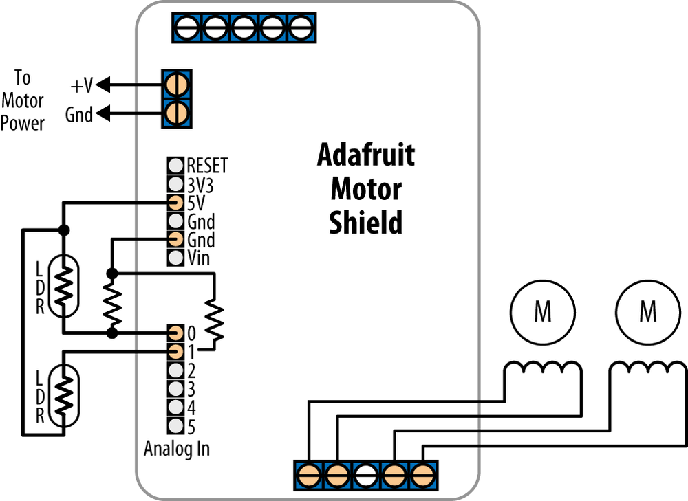
The Adafruit shield supports four connections for motor windings; the sketch that follows has the motors connected to connectors 3 and 4:
/*
 * Brushed_H_Bridge_Direction sketch for Adafruit Motor shield
 * uses photo sensors to control motor direction
 * robot moves in the direction of a light
 */

#include "AFMotor.h"  // adafruit motor shield library

AF_DCMotor leftMotor(3, MOTOR12_1KHZ); // motor #3, 1 KHz pwm uses pin 5
AF_DCMotor rightMotor(4, MOTOR12_1KHZ); // motor #4, 1 KHz pwm uses pin 6

const int MIN_PWM        = 64;  // this can range from 0 to MAX_PWM;
const int MAX_PWM        = 128; // this can range from around 50 to 255;
const int leftSensorPin  = 0;   // analog pins with sensors
const int rightSensorPin = 1;

int sensorThreshold = 0;  // must be more light than this on sensors to move

void setup()
{
}

void loop()
{
  int leftVal  = analogRead(leftSensorPin);
  int rightVal = analogRead(rightSensorPin);

  if(sensorThreshold == 0){  // have the sensors been calibrated ?
  // if not, calibrate sensors to something above the ambient average
     sensorThreshold = ((leftVal + rightVal) / 2) + 100 ;
  }

  if( leftVal > sensorThreshold || rightVal > sensorThreshold)
  {
    // if there is adequate light to move ahead
    setSpeed(rightMotor, map(rightVal,0,1023, MIN_PWM, MAX_PWM));
    setSpeed(leftMotor,  map(leftVal ,0,1023, MIN_PWM, MAX_PWM));
  }
}

void setSpeed(AF_DCMotor &motor, int speed )
{
  if(speed < 0)
  {
    motor.run(BACKWARD);
    speed = -speed;
  }
  else
  {
    motor.run(FORWARD);
  }
  motor.setSpeed(speed);
}
If you have a different shield than the ones mentioned above, you will need to refer to the data sheet and make sure the values in the sketch match the pins used for PWM and direction.
See Also
The data sheet for the Pololu board: http://www.pololu.com/file/0J86/TB6612FNG.pdf
The product page for the Freeduino shield: http://www.nkcelectronics.com/freeduino-arduino-motor-control-shield-kit.html
The product page for the Ardumoto shield: http://www.sparkfun.com/commerce/product_info.php?products_id=9213
The Adafruit Motor Shield documentation and library can be found here: http://www.ladyada.net/make/mshield/
8.12. Driving a Bipolar Stepper Motor
Problem
You have a bipolar (four-wire) stepper motor and you want to step it under program control using an H-Bridge.
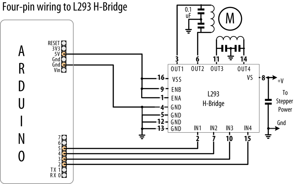
Solution
This sketch steps the motor in response to serial commands. A numeric value followed by a + steps in one direction; a - steps in the other. For example, “24+” steps a 24-step motor through one complete revolution in one direction, and “12-” steps half a revolution in the other direction (Figure 8-15 shows the connections to a four-wire bipolar stepper using the L293 H-Bridge):
/*
 * Stepper_bipolar sketch
 *
 * stepper is controlled from the serial port.
 * a numeric value followed by '+' or '-' steps the motor
 *
 *
 * http://www.arduino.cc/en/Reference/Stepper
 */

#include <Stepper.h>

// change this to the number of steps on your motor
#define STEPS 24

// create an instance of the stepper class, specifying
// the number of steps of the motor and the pins it's
// attached to
Stepper stepper(STEPS, 2, 3, 4, 5);

int steps = 0;


void setup()
{
  // set the speed of the motor to 30 RPM
  stepper.setSpeed(30);
  Serial.begin(9600);
}

void loop()
{
  if ( Serial.available()) {
    char ch = Serial.read();

    if(isDigit(ch)){ // is ch a number?
      steps = steps * 10 + ch - '0';  // yes, accumulate the value
    }
    else if(ch == '+'){
      stepper.step(steps);
      steps = 0;
    }
    else if(ch == '-'){
      stepper.step(steps * -1);
      steps = 0;
    }
  }
}
Discussion
If your stepper requires a higher current than the L293 can provide (600 mA for the L293D), you can use the SN754410 chip for up to 1 amp with the same wiring and code as the L293. For current up to 2 amps, you can use the L298 chip. The L298 can use the same sketch as shown in this recipe’s Solution, and it should be connected as shown in Figure 8-16.
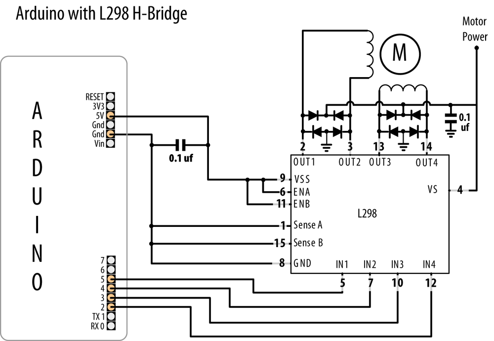
A simple way to connect an L298 to Arduino is to use the SparkFun Ardumoto shield (DEV-09213). This plugs on top of an Arduino board and only requires external connection to the motor windings; the motor power comes from the Arduino Vin (external Voltage Input) pin. In1/2 is controlled by pin 12, and ENA is pin 10. In3/4 is connected to pin 13, and ENB is on pin 11. Make the following changes to the code to use the preceding sketch with Ardumoto:
Stepper stepper(STEPS, 12,13);
Replace all the code inside of setup() with the following:
  pinMode(10, OUTPUT);
  digitalWrite(10, LOW);   // enable A

  pinMode(11, OUTPUT);
  digitalWrite(11, LOW);   // enable B

  stepper.setSpeed(30);   // set the speed of the motor to 30 rpm

  Serial.begin(9600);
See Also
For more on stepper motor wiring, see Tom Igoe’s stepper motor notes: http://www.tigoe.net/pcomp/code/circuits/motors.
8.13. Driving a Bipolar Stepper Motor (Using the EasyDriver Board)
Problem
You have a bipolar (four-wire) stepper motor and you want to step it under program control using the EasyDriver board.
Solution
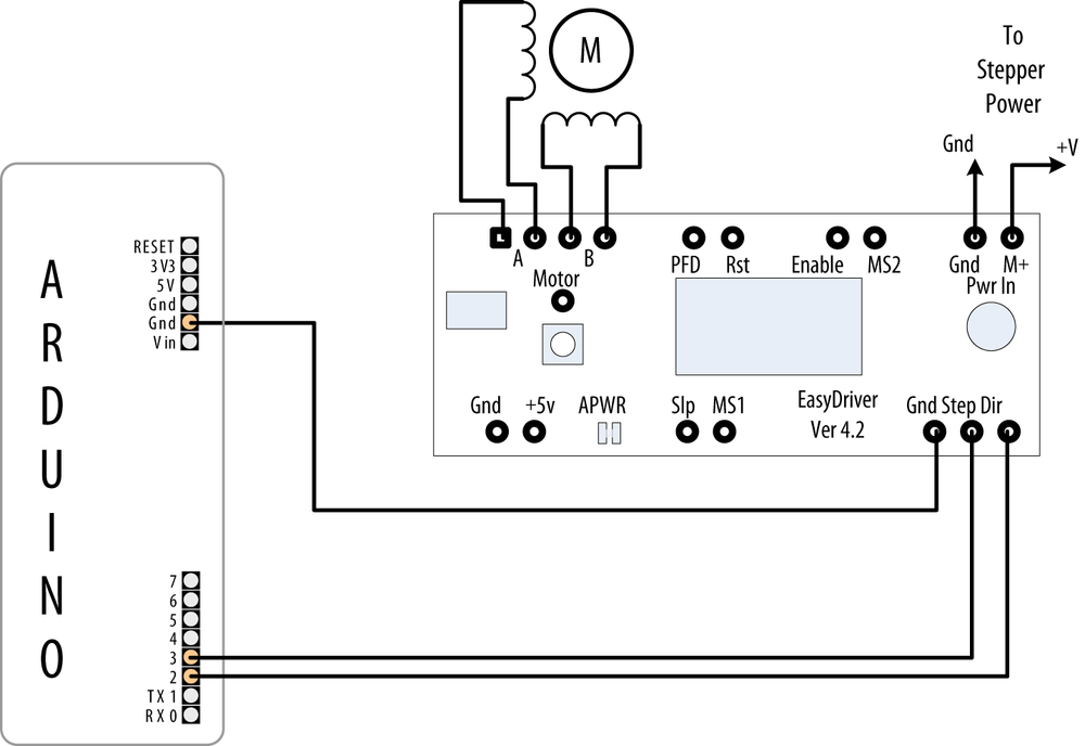
This Solution is similar to Recipe 8.12, and uses the same serial command protocol described there, but it uses the popular EasyDriver board. Figure 8-17 shows the connections.
The following sketch controls the step direction and count from the serial port. Unlike the code in Recipe 8.12, it does not require the Stepper library, because the EasyDriver board handles the control of the motor coils in hardware:
/*
 * Stepper_Easystepper sketch
 *
 * stepper is controlled from the serial port.
 * a numeric value followed by '+' or '-' steps the motor
 *
 */

const int dirPin = 2;
const int stepPin = 3;

int speed = 100;    // desired speed in steps per second
int steps = 0;      // the number of steps to make

void setup()
{
  pinMode(dirPin, OUTPUT);
  pinMode(stepPin, OUTPUT);
  Serial.begin(9600);
}

void loop()
{
  if ( Serial.available()) {
    char ch = Serial.read();

    if(isDigit(ch)){             // is ch a number?
      steps = steps * 10 + ch - '0';        // yes, accumulate the value
    }
    else if(ch == '+'){
      step(steps);
      steps = 0;
    }
    else if(ch == '-'){
      step(-steps);
      steps = 0;
    }
    else if(ch == 's'){
      speed = steps;
      Serial.print("Setting speed to ");
      Serial.println(steps);
      steps = 0;
    }
  }
}

void step(int steps)
{
  int stepDelay = 1000 / speed;  //delay in ms for speed given as steps per sec
  int stepsLeft;

  // determine direction based on whether steps_to_mode is + or -
  if (steps > 0)
  {
    digitalWrite(dirPin, HIGH);
    stepsLeft = steps;
  }
  if (steps < 0)
  {
    digitalWrite(dirPin, LOW);
    stepsLeft = -steps;
  }
  // decrement the number of steps, moving one step each time
  while(stepsLeft > 0)
  {
    digitalWrite(stepPin,HIGH);
    delayMicroseconds(1);
    digitalWrite(stepPin,LOW);
    delay(stepDelay);
    stepsLeft--;      // decrement the steps left
  }
}
Discussion
The EasyDriver board is powered through the pins marked M+ and Gnd (shown in the upper right of Figure 8-17). The board operates with voltages between 8 volts and 30 volts; check the specifications of your stepper motor for the correct operating voltage. If you are using a 5V stepper, you must provide 5 volts to the pins marked Gnd and +5V (these pins are on the lower left of the EasyDriver board) and cut the jumper on the printed circuit board marked APWR (this disconnects the on-board regulator and powers the motor and EasyDriver board from an external 5V supply).
You can reduce current consumption when the motor is not
stepping by connecting the Enable pin to a spare digital output and
setting this HIGH to disable output
(a LOW value enables
output).
Stepping options are selected by connecting the MS1 and MS2 pins
to +5V (HIGH) or Gnd (LOW), as shown in Table 8-2. The default options with the board
connected as shown in Figure 8-17 will use eighth-step
resolution (MS1 and MS2 are HIGH,
Reset is HIGH, and Enable is
LOW).
Resolution | MS1 | MS2 |
Full step | | |
Half step | | |
Quarter step | | |
Eighth step | | |
You can modify the code so that the speed value determines the revolutions per second as follows:
// use the following for speed given in RPM
int speed = 100;    // desired speed in RPM
int stepsPerRevolution = 200;  // this line sets steps for one revolution
Change the step function so that the first line is as follows:
int stepDelay = 60L * 1000L / stepsPerRevolution / speed; // speed as RPM
Everything else can remain the same, but now the speed command you send will be the RPM of the motor when it steps.
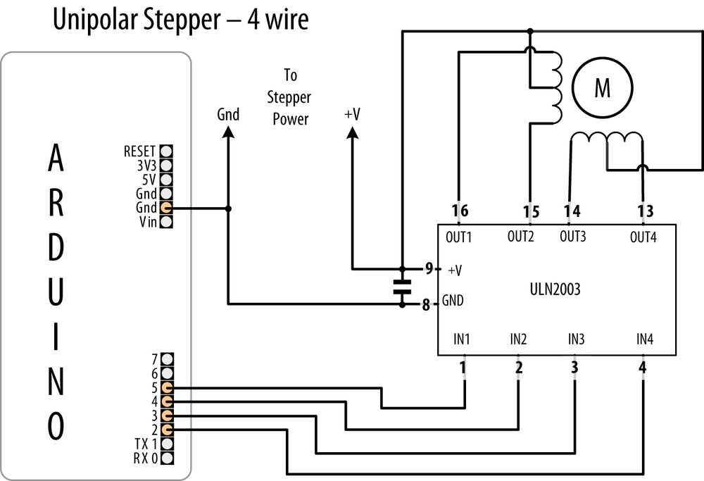
8.14. Driving a Unipolar Stepper Motor (ULN2003A)
Problem
You have a unipolar (five- or six-wire) stepper motor and you want to control it using a ULN2003A Darlington driver chip.
Solution
Connect a unipolar stepper as shown in Figure 8-18. The +V connection goes to a power supply rated for the voltage and current needed by your motor.
The following sketch steps the motor using commands from the serial port. A numeric value followed by a + steps in one direction; a - steps in the other:
/*
 * Stepper sketch
 *
 * stepper is controlled from the serial port.
 * a numeric value followed by '+' or '-' steps the motor
 *
 *
 * http://www.arduino.cc/en/Reference/Stepper
 */

#include <Stepper.h>

// change this to the number of steps on your motor
#define STEPS 24

// create an instance of the stepper class, specifying
// the number of steps of the motor and the pins it's
// attached to
Stepper stepper(STEPS, 2, 3, 4, 5);

int steps = 0;


void setup()
{
  stepper.setSpeed(30);    // set the speed of the motor to 30 RPMs
  Serial.begin(9600);
}

void loop()
{
  if ( Serial.available()) {
    char ch = Serial.read();

    if(isDigit(ch)){             // is ch a number?
      steps = steps * 10 + ch - '0';        // yes, accumulate the value
    }
    else if(ch == '+'){
      stepper.step(steps);
      steps = 0;
    }
    else if(ch == '-'){
      stepper.step(steps * -1);
      steps = 0;
    }    else if(ch == 's'){
      stepper.setSpeed(steps);
      Serial.print("Setting speed to ");
      Serial.println(steps);
      steps = 0;
    }
  }
}
Discussion
This type of motor has two pairs of coils, and each coil has a connection to the center. Motors with only five wires have both center connections brought out on a single wire. If the connections are not marked, you can identify the wiring using a multimeter. Measure the resistance across pairs of wires to find the two pairs of wires that have the maximum resistance. The center tap wire should have half the resistance of the full coil. A step-by-step procedure is available at http://techref.massmind.org/techref/io/stepper/wires.asp.