
Audio Output
9.0 Introduction
There are millions of Google results for “Arduino music project” and there is only space in this chapter to introduce Arduino audio techniques and some examples to get you started. Arduino wasn’t built to be a sophisticated audio synthesizer, but it can certainly produce sound through an output device such as a speaker.
This chapter shows how to create noise, play prerecorded sounds and create some simple output, and even experiment with sound synthesis.
If you want inspiration for your project, look through some of the many web sites featuring music projects:
- The Arduino music project hub: https://create.arduino.cc/projecthub/projects/tags/music
- Arduino blog entries about music: https://blog.arduino.cc/category/music/
Here are just two excellent examples of what can be achieved with Arduino, some hardware and lots of creativity:
- A laser harp http://makezine.com/projects/laser-harp/
- A theremin. See Recipe 9.6 for a very simple version of this early electronic instrument, but the real thing can be made with information from: http://www.gaudi.ch/OpenTheremin/
Sound is produced by vibrating air. A sound has a distinctive pitch if the vibration repeats regularly. The Arduino can create sound by driving a loudspeaker or Piezo device (a small ceramic transducer that produces sound when pulsed), converting electronic vibrations into speaker pulses that vibrate the air. The pitch (frequency) of the sound is determined by the time it takes to pulse the speaker in and out; the shorter the amount of time, the higher the frequency.
Note
There are two types of Piezos you are likely to encounter. A Piezo speaker can produce sounds across a range of frequencies. A Piezo buzzer, on the other hand, includes oscillator circuitry that cause it to buzz at a fixed frequency when you apply power. The Piezo-based solutions in this chapter assume you are working with a Piezo speaker, not a buzzer.
The unit of frequency is measured in hertz, and it refers to the number of times the signal goes through its repeating cycle in one second. The range of human hearing is from around 20 hertz (Hz) up to 20,000 hertz (although it varies by person and changes with age).
The Arduino software includes a tone function for producing sound. Recipes 9.1 and 9.2 show how to use this function to make sounds and tunes. The tone function uses hardware timers. On a standard Arduino board (the Uno and similar boards), only one tone can be produced at a time. When you use the tone function, it will tie up the timer used for analogWrite on pins 3 and 11 so you’ll need to choose different pins if you need analog output. To overcome this limitation, Recipe 9.3 shows how to use an enhanced tone library for multiple tones, and Recipe 9.4 shows how sound can be produced without using the tone function or hardware timers.
The sound that can be produced by pulsing a speaker is limited and does not sound very musical. The output is a square wave (see Figure 9-1), which sounds harsh and more like an antique computer game than a musical instrument.

Generating sound using digital pulses
It is difficult for basic boards like the Arduino Uno to produce more musically complex sounds without external hardware. You can add a shield that extends the Uno’s capabilities; [Link to Come] shows how to use the Adafruit Wave Shield to play back audio files from a memory card on the shield.
Some of the more recent Arduino boards have a Digital to Analog Converter output (DAC), which can produce high quality audio - either playing sounds files from SD cards, or synthesizing sound in software (see Recipe 1.8). Another option that newer boards have is I2S (Inter-IC Sound). This is a digital interface for communicating with external chips that produce high quality stereo audio interfaces - both input and output.
You can also use Arduino to control an external device that is built to make sound. Recipe 9.5 shows how to send Musical Instrument Digital Interface (MIDI) messages to a MIDI device. These devices produce high-quality sounds of a huge variety of instruments and can produce the sounds of many instruments simultaneously. The sketch in Recipe 9.5 shows how to generate MIDI messages to play a musical scale.
Recipe 9.6 provides an overview of an application called Auduino that uses complex software processing to synthesize sound. Recipe 9.7 shows a more advanced audio synthesis library.
If you want to explore sophisticated musical applications then the 32-bit Teensy boards from PJRC (https://www.pjrc.com/teensy/index.html) are a good choice. There is also a well developed audio library that makes use of the DSP capabilities of the chip on the Teensy to provide complex synthesis and audio effects using the DAC that is also built in, giving true analog audio output. An audio shield is available for these boards that has a microSD card reader and an I2S audio chip that produces stereo 16-bit 44.1 kHz audio output, as well as stereo audio in. The Teensy can also serve as a native USB MIDI, and audio input and output device.
SparkFun offers a range of audio modules, including an Audio-Sound Breakout (part number WIG-11125) and MP3 player shield (part number DEV-12660).
The Arduino Zero, MKR1000 and MKRZero have a DAC pin, if you install the experimental AudioZero library they can play a WAV file from an SD card.
This chapter covers the many ways you can generate sound electronically. If you want to make music by getting Arduino to play acoustic instruments (such as glockenspiels, drums, and acoustic pianos), you can employ actuators such as solenoids and servos that are covered in Chapter 8.
Many of the recipes in this chapter will drive a small speaker or Piezo device. The circuit for connecting one of these to an Arduino pin is shown in Figure 9-2.

Connecting to an audio transducer
The volume control is a variable resistor, the value is not critical and anything from 200 to 500 ohms would work. The capacitor is a 100 microfarad electrolytic with the positive end connected to the Arduino pin. A speaker will work regardless of which wire is attached to ground, but a Piezo is polarized, so connect the negative wire (usually black) to the Gnd pin.
Alternatively, you can connect the output to an external audio amplifier. Recipe 9.6 shows how an output pin can be connected to an audio jack.
Warning
If you connect one of these circuits to headphones using an audio jack, make sure you set the volume to a safe level before putting the headphones on. Depending on which board you are using, and how you have wired it, the sound could be quite loud.
9.1 Playing Tones
Problem
You want to produce audio tones through a speaker or other audio transducer. You want to specify the frequency and duration of the tone.
Solution
Use the Arduino tone function. This sketch plays a tone with the frequency set by a variable resistor (or other sensor) connected to analog input 0 (see Figure 9-3):
/*
 * Tone sketch
 *
 * Plays tones through a speaker on digital pin 9
 * Frequency determined by values read from analog pin
 */

const int speakerPin = 9;    // connect speaker to pin 9
const int pitchPin = A0;     // pot that will determine the frequency of the tone

void setup()
{
}

void loop()
{
  int sensor0Reading = analogRead(pitchPin);    // read input to set frequency

  // map the analog readings to a meaningful range
  int frequency = map(sensor0Reading, 0, 1023, 100, 5000); // 100Hz to 5kHz

  int duration = 250;   // how long the tone lasts
  tone(speakerPin, frequency, duration); // play the tone
  delay(1000); // pause one second
}

Connections for the Tone sketch
The tone function can take up to three parameters: the pin attached to the speaker, the frequency to play (in hertz), and the length of time (in milliseconds) to play the note. The third parameter is optional. If it is omitted, the note will continue until there is another call to tone, or a call to noTone. The value for the frequency is mapped to sensible values for audio frequencies in the following line:
int frequency = map(sensor0Reading, 0, 1023, 100, 5000); //100Hz to 5kHz
This variation uses a second variable resistor (the bottom right pot in Figure 9-3) to set the duration of the tone:
const int speakerPin = 9;    // connect speaker to pin 9
const int pitchPin = A0;     // input that determines frequency of the tone
const int durationPin = A1;  // input that will determine the duration of the tone

void setup()
{
}

void loop()
{
  int sensor0Reading = analogRead(pitchPin);    // read input for frequency
  int sensor1Reading = analogRead(durationPin); // read input for duration

  // map the analog readings to a meaningful range
  int frequency  = map(sensor0Reading, 0, 1023, 100, 5000); // 100Hz to 5kHz
  int duration = map(sensor1Reading, 0, 1023, 100, 1000);   // dur 0.1-1 second
  tone(speakerPin, frequency, duration); // play the tone
  delay(duration); // wait for the tone to finish
}
Another variation is to add a switch so that tones are generated only when the switch is pressed.
Enable an input with pull-up resistors in setup with the following line (see Recipe 5.2 for a connection diagram and explanation). You’ll also need to define inputPin to specify the pin you want to use:
pinMode(inputPin, INPUT_PULLUP);
Modify the loop code so that the tone and delay functions are only called when the switch is pressed:
if (digitalRead(inputPin) == LOW)  // read input value
{
  tone(speakerPin, frequency, duration); // play the tone
  delay(duration); //wait for the tone to finish
}
You can use almost any audio transducer to produce sounds with Arduino. Small speakers work very well. Piezo transducers also work and are inexpensive, robust, and easily salvaged from old audio greeting cards. Piezos draw little current (they are high-resistance devices), so they can be connected directly to the pin. Speakers are usually of much lower resistance and need a resistor to limit the current flow. The components to build the circuit pictured in Figure 9-3 should be easy to find.
See Also
You can achieve enhanced functionality using the Tone library by Brett Hagman that is described in Recipe 9.3.
9.2 Playing a Simple Melody
Problem
You want Arduino to play a simple melody.
Solution
You can use the tone function described in Recipe 9.1 to play sounds corresponding to notes on a musical instrument. This sketch uses tone to play a string of notes, the “Hello world” of learning the piano, “Twinkle, Twinkle Little Star”:
/*
 * Twinkle sketch
 * Plays "Twinkle, Twinkle Little Star"
 * Speaker is connected to digital pin 9
 */

const int speakerPin = 9; // connect speaker to pin 9

char noteNames[] = {'C','D','E','F','G','a','b'};
unsigned int frequencies[] = {262,294,330,349,392,440,494};
const byte noteCount = sizeof(noteNames); // number of notes (7 here)

//notes, a space represents a rest
char score[] = "CCGGaaGFFEEDDC GGFFEEDGGFFEED CCGGaaGFFEEDDC ";
const byte scoreLen = sizeof(score); // the number of notes in the score

void setup()
{
}

void loop()
{
  for (int i = 0; i < scoreLen; i++)
  {
    int duration = 333;  // each note lasts for a third of a second
    playNote(score[i], duration); // play the note
    delay(duration/10); // slight pause to separate the notes
  }

  delay(4000); // wait four seconds before repeating the song
}

void playNote(char note, int duration)
{
  // play the tone corresponding to the note name
  for (int i = 0; i < noteCount; i++)
  {
    // try and find a match for the noteName to get the index to the note
    if (noteNames[i] == note) // find a matching note name in the array
      tone(speakerPin, frequencies[i], duration); //  play the note
  }
  // if there is no match then the note is a rest, so just do the delay
  delay(duration);
}
noteNames is an array of characters to identify notes in a score. Each entry in the array is associated with a frequency defined in the notes array. For example, note C (the first entry in the noteNames array) has a frequency of 262 Hz (the first entry in the notes array).
score is an array of notes representing the note names you want to play (lowercase notes are an octave higher than the uppercase notes):
// a space represents a rest
char score[] = "CCGGaaGFFEEDDC GGFFEEDGGFFEED CCGGaaGFFEEDDC ";
Each character in the score that matches a character in the noteNames array will make the note play. The space character is used as a rest, but any character not defined in noteNames will also produce a rest (no note playing).
The sketch calls playNote with each character in the score and a duration for the notes of one-third of a second.
The playNote function does a lookup in the noteNames array to find a match and uses the corresponding entry in the frequencies array to get the frequency to sound.
Every note has the same duration. If you want to specify the length of each note, you can add the following code to the sketch:
byte beats[scoreLen] = {1,1,1,1,1,1,2,  1,1,1,1,1,1,2,1,
                        1,1,1,1,1,1,2,  1,1,1,1,1,1,2,1,
                        1,1,1,1,1,1,2,  1,1,1,1,1,1,2};
byte beat = 180; // beats per minute for eighth notes
unsigned int speed = 60000 / beat; // the time in ms for one beat
beats is an array showing the length of each note: 1 is an eighth note, 2 a quarter note, and so on.
beat is the number of beats per minute.
speed is the calculation to convert beats per minute into a duration in milliseconds.
The only change to the loop code is to set the duration to use the value in the beats array. Change:
int duration = 333; // each note lasts for a third of a second
to:
int duration = beats[i] * speed; // use beats array to determine duration
9.3 Generating More Than One Simultaneous Tone
Problem
You want to play two tones at the same time. The Arduino Tone library only produces a single tone on a standard board, and you want two simultaneous tones. Note that the Mega board has more timers and can produce up to six tones.
Solution
The Arduino Tone library is limited to a single tone because a different timer is required for each tone, and although a standard Arduino board has three timers, one is used for the millis function and another for servos. This recipe uses a library written by Brett Hagman, the author of the Arduino tone function. The library enables you to generate multiple simultaneous tones. You can download it from https://github.com/bhagman/Tone or simply install it with the Library Manager.
This is an example sketch that plays part of Twinkle Twinkle Little Star with the same notes across two octaves:
/*
 * Dual Tones
 * Plays Twinkle Twinkle Little Star over two octaves.
 */
#include <Tone.h>

int notes1[] = {NOTE_C3, NOTE_C3, NOTE_G3, NOTE_G3, NOTE_A4, NOTE_A4,
                NOTE_G3, NOTE_F3, NOTE_F3, NOTE_E3, NOTE_E3, NOTE_D3,
                NOTE_D3, NOTE_C3 };
int notes2[] = {NOTE_C3, NOTE_C3, NOTE_G3, NOTE_G3, NOTE_A4, NOTE_A4,
                NOTE_G3, NOTE_F3, NOTE_F3, NOTE_E3, NOTE_E3, NOTE_D3,
                NOTE_D3, NOTE_C3 };
const byte scoreLen = sizeof(notes1)/sizeof(notes1[0]); // number of notes

// You can declare the tones as an array
Tone notePlayer[2];

void setup(void)
{
  notePlayer[0].begin(11);
  notePlayer[1].begin(12);
}

void loop(void)
{
  for (int i = 0; i < scoreLen; i++)
  {
    notePlayer[0].play(notes1[i]);
    delay(100); // Slight delay before starting the next note
    notePlayer[1].play(notes2[i]);
    delay(400);
    notePlayer[0].stop();
    notePlayer[1].stop();
    delay(30);
  }
  delay(1000);
}
Discussion
To mix the output of the two tones to a single speaker, use 500 ohm resistors from each output pin and tie them together at the speaker. The other speaker lead connects to Gnd, as shown in the previous sketches.
On a standard Arduino board, the first tone will use timer 2 (so PWM on pins 9 and 10 will not be available); the second tone uses timer 1 (preventing the Servo library and PWM on pins 11 and 12 from working). On a Mega board, each simultaneous tone will use timers in the following order: 2, 3, 4, 5, 1, 0. At the time of this writing, this library uses features that are specific to the AVR architecture and is not supported on ARM boards or MegaAVR boards such as the Uno WiFi R2 or the Nano Every.
When you play two notes that are the same frequency, or are the same note from a different octave, you may notice an effect known as a beat that is similar to a tremelo. This happens because the two channels are not in perfect sync. This effect is used to tune guitar strings manually: the beat ceases to be heard once the string is in tune with the reference note.
Warning
Playing three simultaneous notes on a standard Uno Arduino board, or more than six on a Mega, is possible, but millis and delay will no longer work properly. It is safest to use only two simultaneous tones (or five on a Mega).
9.4 Generating Audio Tones without Interfering with PWM
Problem
You want to produce sounds through a speaker or other audio transducer, and you need to generate the tone in software instead of with a timer; for example, if you need to use analogWrite on pin 3 or 11.
Solution
The tone function discussed in earlier recipes is easy to use, but it requires a hardware timer, which may be needed for other tasks such as analogWrite. This code does not use a timer, but it will not do anything else while the note is played. Unlike the Arduino tone function, the playTone function described here will block—it will not return until the note has finished.
The sketch plays six notes, each one twice the frequency of (an octave higher than) the previous one. The playTone function generates a tone for a specified duration on a speaker or Piezo device connected to a digital output pin and ground; see Figure 9-4:
/*
 * Tone and fade sketch
 * Plays tones while fading an LED
 */
byte speakerPin = 9;
byte ledPin = 3;

void setup()
{
  pinMode(speakerPin, OUTPUT);
}

void playTone(int period, int duration)
{
  // period is one cycle of tone
  // duration is how long the pulsing should last in milliseconds
  int pulse = period / 2;
  for (long i = 0; i < duration * 1000L; i += period )
  {
    digitalWrite(speakerPin, HIGH);
    delayMicroseconds(pulse);
    digitalWrite(speakerPin, LOW);
    delayMicroseconds(pulse);
  }
}

void fadeLED(){
  // These two static variables are assigned initial values
  // only the first time the function is called.
  static int brightness = 0;
  static int changeval  = 5;

  analogWrite(ledPin, brightness);

  // If we've exceeded the limits of analogWrite
  brightness += changeval;
  if (brightness >= 255 || brightness <= 0)
    changeval *= -1; // Change direction

  delay(2);
}

void loop()
{
  // a note with period of 15289 is deep C (second lowest C note on piano)
  for(int period=15289; period >= 477;  period=period / 2)  // play 6 octaves
  {
    playTone(period, 200); // play tone for 200 milliseconds
    fadeLED();
  }
}

Connections for speaker and LED
Discussion
Two values are used by playTone: period and duration. The variable period represents the time for one cycle of the tone to play. The speaker is pulsed high and then low for the number of microseconds given by period. The for loop repeats the pulsing for the number of milliseconds given in the duration argument.
If you prefer to work in frequency rather than period, you can use the reciprocal relationship between frequency and period; period is equal to 1 divided by frequency. You need the period value in microseconds; because there are 1 million microseconds in one second, the period is calculated as 1000000L / frequency (the “L” at the end of that number tells the compiler that it should calculate using long integer math to prevent the calculation from exceeding the range of a normal integer—see the explanation of long integers in Recipe 2.2):
void playFrequency(int frequency, int duration)
{
  int period = 1000000L / frequency;
  int pulse = period / 2;
The rest of the code is the same as playTone:
  for (long i = 0; i < duration * 1000L; i += period )
  {
    digitalWrite(speakerPin, HIGH);
    delayMicroseconds(pulse);
    digitalWrite(speakerPin, LOW);
    delayMicroseconds(pulse);
  }
}
The code in this recipe stops and waits until a tone has completed before it can do any other processing. It is possible to produce the sound in the background (without waiting for the sound to finish) by putting the sound generation code in an interrupt handler. The source code for the tone function that comes with the Arduino distribution shows how this is done.
See Also
Here are some examples of more complex audio synthesis that can be accomplished with the Arduino:
- Pulse-Code Modulation
-
PCM allows you to approximate analog audio using digital signaling. An Arduino wiki article that explains how to produce 8-bit PCM using a timer is available at http://www.arduino.cc/playground/Code/PCMAudio.
- Pocket Piano shield
-
Modern Device’s Fluxamasynth Shield is a 64-voice polyphonic synthesizer shield for Arduino; see https://moderndevice.com/product/fluxamasynth-shield/.
9.5 Controlling MIDI
Problem
You want to get a MIDI synthesizer to play music using Arduino.
Solution
To connect to a MIDI device, you need a five-pin DIN plug or socket. If you use a socket, you will also need a lead to connect to the device. Connect the MIDI connector to Arduino using a 220 ohm resistor, as shown in Figure 9-5.
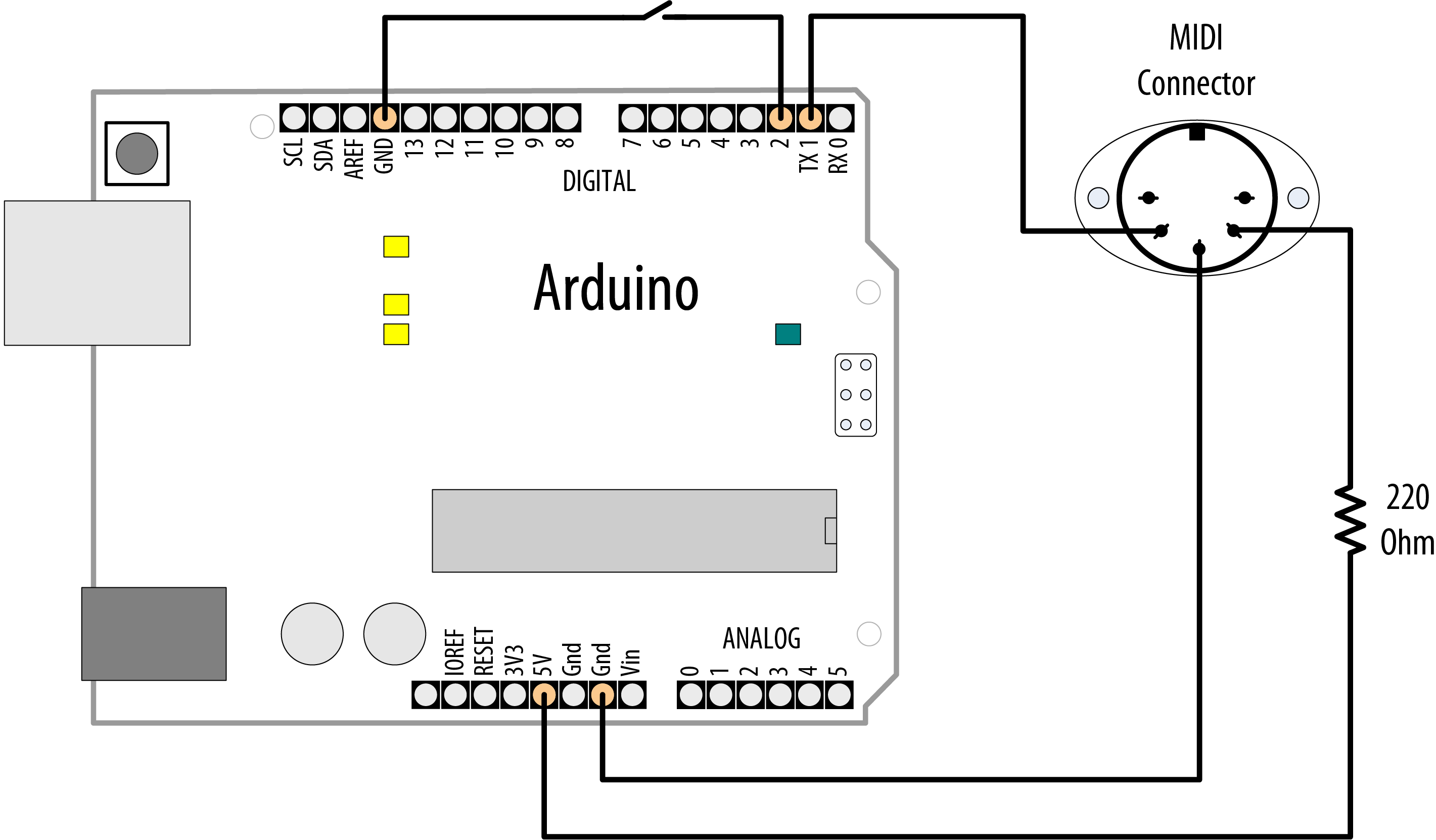
MIDI connections
To upload the code onto Arduino, you should disconnect the MIDI device, as it may interfere with the upload. After the sketch is uploaded, connect a MIDI sound device to the Arduino output. A musical scale will play each time you press the button connected to pin 2:
/*
 * midiOut sketch
 * Sends MIDI messages to play a scale on a MIDI instrument
 * each time the switch on pin 2 is pressed
*/

// these numbers specify which note to play
const byte notes[8] = {60, 62, 64, 65, 67, 69, 71, 72};
const int num_notes = sizeof(notes)/ sizeof(notes[0]);

const int switchPin = 2;
const int ledPin = LED_BUILTIN;

void setup() {
  Serial.begin(31250);
  pinMode(switchPin, INPUT_PULLUP);
  pinMode(ledPin, OUTPUT);
}

void loop() {
  if (digitalRead(switchPin) == LOW)
  {
    for (byte noteNumber = 0; noteNumber < num_notes; noteNumber++)
    {
      // Play the note
      playMidiNote(1, notes[noteNumber], 127);
      digitalWrite(ledPin, HIGH);
      delay(70); // Hold the note

      // Stop playing the note (velocity of 0)
      playMidiNote(1, notes[noteNumber], 0);
      digitalWrite(ledPin, HIGH);
      delay(30);
    }
  }
}

void playMidiNote(byte channel, byte note, byte velocity)
{
  byte midiMessage= 0x90 + (channel - 1);
  Serial.write(midiMessage);
  Serial.write(note);
  Serial.write(velocity);
}
Discussion
This sketch uses the serial TX pin to send MIDI information. The circuit connected to pin 1 may interfere with uploading code to the board. Remove the wire from pin 1 while you upload, and plug it back in afterward.
MIDI was originally used to connect digital musical instruments together so that one could control another. The MIDI specification describes the electrical connections and the messages you need to send.
MIDI is actually a serial connection (at a nonstandard serial speed, 31,250 baud), so Arduino can send and receive MIDI messages using its serial port hardware from pins 0 and 1. Because the serial port is occupied by MIDI messages, you can’t print messages to the Serial Monitor, so the sketch flashes the onboard LED each time it sends a note.
Each MIDI message consists of at least one byte. This byte specifies what is to be done. Some commands need no other information, but other commands need data to make sense. The message in this sketch is note on, which needs two pieces of information: which note and how loud. Both of these bits of data are in the range of zero to 127.
The sketch initializes the serial port to a speed of 31,250 baud; the other MIDI-specific code is in the function playMidiNote:
void playMidiNote(byte channel, byte note, byte velocity)
{
  byte midiMessage= 0x90 + (channel - 1);
  Serial.write(midiMessage);
  Serial.write(note);
  Serial.write(velocity);
}
This function takes three parameters and calculates the first byte to send using the channel information.
MIDI information is sent on different channels between 1 and 16. Each channel can be set to be a different instrument, so multichannel music can be played. The command for note on (to play a sound) is a combination of 0x90 (the top four bits at b1001), with the bottom four bits set to the numbers between b0000 and b1111 to represent the MIDI channels. The byte represents channels using 0 to 15 for channels 1 to 16, so 1 is subtracted first.
Then the note value and the volume (referred to as velocity in MIDI, as it originally related to how fast the key was moving on a keyboard) are sent.
The serial write statements specify that the values must be sent as bytes (rather than as the ASCII value). println is not used because a line return character would insert additional bytes into the signal that are not wanted.
The sound is turned off by sending a similar message, but with velocity set to 0.
This recipe works with MIDI devices having five-pin DIN MIDI in connectors. If your MIDI device only has a USB connector, this will not work. It will not enable the Arduino to control MIDI music programs running on your computer without additional hardware (a MIDI-to-USB adapter). Although Arduino has a USB connector, your computer recognizes it as a serial device, not a MIDI device.
See Also
To send and receive MIDI, have a look at the MIDI library available at http://www.arduino.cc/playground/Main/MIDILibrary.
MIDI messages are described in detail at http://www.midi.org/techspecs/midimessages.php.
The SparkFun MIDI shield is a kit that includes MIDI in and out connectors, some buttons and an optoisolator to keep the MIDI device and the Arduino electrically isolated. See https://www.sparkfun.com/products/12898.
To set an Arduino Uno up as a native USB MIDI device, see [Link to Come].
The Teensy board is also able to be programmed to be a native USB MIDI device.
9.6 Making an Audio Synthesizer
Problem
You want to generate complex sounds similar to those used to produce electronic music.
Solution
The simulation of audio oscillators used in a sound synthesizer is complex, but Peter Knight has created a sketch called Auduino that enables Arduino to produce more complex and interesting sounds. Because it uses many low-level capabilities, Auduino is unlikely to run on anything other than 8-bit boards based on the ATmega such as the Uno.
Download the sketch by following the link on http://code.google.com/p/tinkerit/wiki/Auduino.
Connect five 4.7K ohm linear potentiometers to analog pins 0 through 4, as shown in Figure 9-6. Potentiometers with full-size shafts are better than small presets because you can easily twiddle the settings. Pin 3 is used for audio output and is connected to an amplifier using a jack plug.
Warning
The voltage level (5 volts) is higher than audio amplifiers expect, so you may need to use a 4.7K variable resistor to reduce the voltage (connect one end to pin 9 and the other end to ground; then connect the slider to the tip of the jack plug. The barrel of the jack plug is connected to ground).
Discussion
The sketch code is complex because it is directly manipulating hardware timers to generate the desired frequencies, which are transformed in software to produce the audio effects. It is not included in the text because you do not need to understand the code to use Auduino.
Auduino uses a technique called granular synthesis to generate the sound. It uses two electronically produced sound sources (called grains). The variable resistors control the frequency and decay of each grain (inputs 0 and 2 for one grain and inputs 3 and 1 for the other). Input 4 controls the synchronization between the grains.
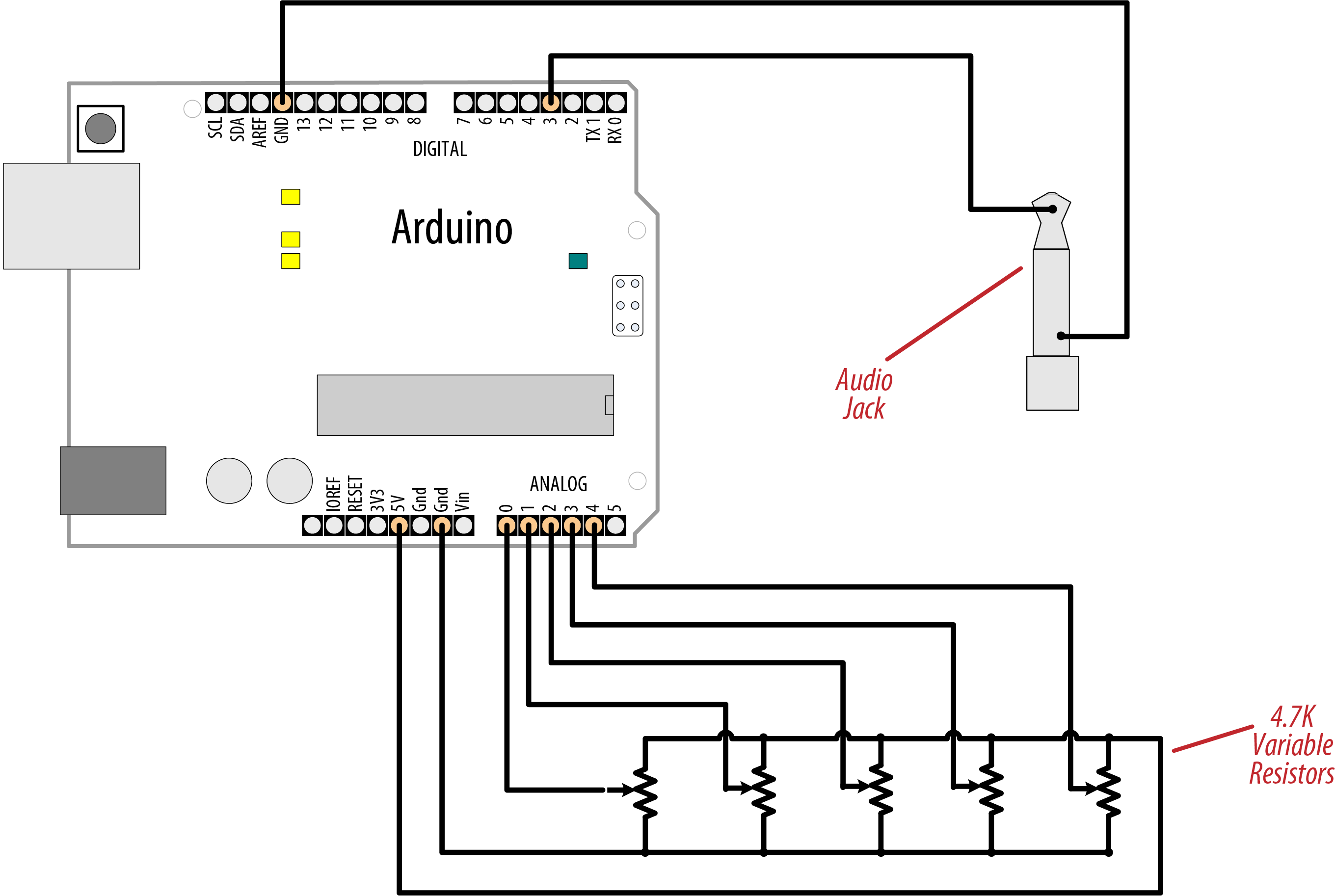
Wiring diagram for controlling and listening to Auduino
If you want to tweak the code, you can change the scale used to calculate the frequency. The default setting is pentatonic, but you can comment that out and uncomment another option to use a different scale.
Be careful when adding code to the main loop, because the sketch is highly optimized and additional code could slow things down too much, causing the audio synthesis to not work well.
You can replace any of the pots with sensors that can produce an analog voltage signal (see Chapter 6). For example, a photoresistor (see Recipe 6.3) or a distance sensor (the analog output described toward the end of Recipe 6.5) connected to one of the frequency inputs (pin 0 or 3) would enable you to control the pitch by moving your hand closer to or farther from the sensor (look up “theremin” in Wikipedia or on Google to read more about this musical instrument that is played by sensing hand movement).
See Also
Video demonstration of Auduino: http://www.vimeo.com/2266458
Wikipedia article explaining granular synthesis: http://en.wikipedia.org/wiki/Granular_synthesis
Wikipedia article on the theremin: http://en.wikipedia.org/wiki/Theremin
9.7 Attain High-Quality Audio Synthesis
Problem
You want to generate higher quality audio than is possible with the Tone library on an 8-bit board, which can generally produce only square wave signals without additional hardware. For example, you want to play music with sine waves, play back WAV files, or perform advanced sound synthesis without additional hardware.
Solution
As you saw in Recipe 1.8, SAMD-based boards have a digital-to-analog converter (DAC) on one pin that can generate true voltages between 0V and the operating voltage (3.3V) of the board. This, coupled with the higher speed of 32-bit boards, allows you to generate complex waveforms. Connect your board to a transducer as shown in Figure 9-2, but instead of connecting your transducer to pin 9, use the DAC pin (Analog 0 on the Arduino Zero, Adafruit Metro M0, and SparkFun RedBoard Turbo). Install Mozzi from https://github.com/sensorium/Mozzi (see Recipe 16.2) and run the following script:
/*
 * Mozzi Melody
 * Play the Chimes of Big Ben
 */

#include <MozziGuts.h>
#include <Oscil.h> // oscillator template
#include <tables/sin2048_int8.h> // sine table for oscillator
#include <EventDelay.h>
#include <mozzi_midi.h>

#define CONTROL_RATE 64 // Control rate in Hz, use powers of 2

enum notes
{
  E3 = 52, B4 = 59, E4 = 64, F4S = 66, G4S = 68, REST = 0
};

int score[] = { E4, G4S, F4S, B4, REST,
                E4, F4S, G4S, E4, REST,
                G4S, E4, F4S, B4, REST,
                B4, F4S, G4S, E4, REST,
                E3, REST, E3, REST, E3, REST, E3, REST };
const byte scoreLen = sizeof(score) / sizeof(score[0]);

byte beats[scoreLen] = {2, 2, 2, 2, 2,
                        2, 2, 2, 2, 2,
                        2, 2, 2, 2, 2,
                        2, 2, 2, 2, 10,
                        4, 4, 4, 4, 4, 4, 4, 10};
unsigned int beat_ms = 60000 / 180; // the time in ms for 1/8 note

const int pauseTime = 200; // pause between notes
int currNote = 0; // index of the note we're playing
bool pausing = false; // Mini-rest between beats

Oscil <SIN2048_NUM_CELLS, AUDIO_RATE> aSin(SIN2048_DATA); // Sine wave
EventDelay kChangeNoteDelay; // Delay object

void setup() {
  startMozzi(CONTROL_RATE);
  kChangeNoteDelay.start();
}

void updateControl() {

  if (kChangeNoteDelay.ready()) { // Is the delay up?
    pausing = !pausing; // Toggle rest state
    if (pausing) {
      aSin.setFreq(0); // set the frequency
      kChangeNoteDelay.set(pauseTime); // Hold the rest for 200ms
    } else {
      if (currNote >= scoreLen) {
        currNote = 0; // Go back to the beginning when done
      }
      int duration = beats[currNote] * beat_ms; // use beats array to determine duration
      kChangeNoteDelay.set(duration - pauseTime); // Set the note duration
      aSin.setFreq(mtof(score[currNote])); // set the frequency
      currNote++;
    }
    kChangeNoteDelay.start();
  }
}

int updateAudio() {
  return aSin.next();
}

void loop() {
  audioHook(); // You must have this in your loop
}
Discussion
Mozzi is an advanced audio synthesis library for Arduino and compatible boards. Although it supports 8-bit boards, it uses PWM, so the sound quality is limited. But on 32-bit boards such as SAMD-based boards and the Teensy, it excels. Mozzi is a powerful framework with many features, and it includes dozens of sample programs.
The sketch sets things up by including the Mozzi header files, and defining the Mozzi control rate, which determines how often the update functions are called. The sketch then defines an enum of the notes used in this sketch. For convenience, it uses MIDI notes (see Recipe 9.5). Because MIDI notes can be represented as integers, this allows you to use them in an enum, which in turn makes it easy to use their symbolic names in an array of integers. You could accomplish the same thing with #defines, and in that case, you could use floating point frequencies instead of MIDI numbers.
Similar to the sketch in Recipe 9.2, this sketch uses an array to represent the score, and an array to represent how many beats each note should be held. It then initializes some variables and objects that are used later in the sketch.
In setup(), the sketch initializes the Mozzi system, and starts a timer. This is where things become noticeably different from a typical Arduino sketch. Instead of using delay() to wait until it’s time to play the next note, all the changes take place in the updateControl() function. When the timer is up, the sketch toggles the pausing state, which is used to determine when to take a brief pause between notes. If pausing is true, the sketch goes silent for 200ms. Otherwise, the sketch advances to the next note in the score array, calculates the duration, and sets the frequency by converting the MIDI number to a frequency in Hertz. It then sets the timer to the duration of the note (subtracting the pause time so as to keep closer to standard musical timing).
See Also
The ArduTouch board and software is an Arduino-compatible music synthesizer kit that has similar capabilities to Mozzi. You can also run the ArduTouch software on an Arduino Uno. https://cornfieldelectronics.com/cfe/products/buy.php?productId=synth
The Teensy Audio library supports high-quality audio for Teensy boards. It includes polyphonic capabilities, as well as audio recording, synthesis, filtering, and more: https://www.pjrc.com/teensy/td_libs_Audio.html.