
Visual Output
7.0 Introduction
Visual output lets the Arduino convey information to users, and toward that end, the Arduino supports a broad range of LED devices. (Arduino can also display information with graphical display panels, which is covered in Chapter 11.) Before delving into the recipes in this chapter, we’ll discuss Arduino digital and analog output and explain how Arduino works with light-emitting diodes (LEDs). This introduction will be a good starting point if you are not yet familiar with using digital and analog outputs (digitalWrite and analogWrite) or with using LEDs in a circuit. The recipes in this chapter cover everything from simple single-LED displays to creating the illusion of motion (Recipe 7.7) and showing shapes (Recipe 7.9).
Digital Output
All the pins that can be used for digital input can also be used for digital output. Chapter 5 provided an overview of the Arduino pin layout; you may want to look through the introduction section in that chapter if you are unfamiliar with connecting things to Arduino pins.
Digital output causes the voltage on a pin to be either high (5 or 3.3 volts depending on board) or low (0 volts). Use the digitalWrite(outputPin, value) function to turn something on or off. The function has two parameters: outputPin is the pin to control, and value is either HIGH (5 or 3.3 volts) or LOW (0 volts).
For the pin voltage to respond to this command, the pin must have been set in output mode using the pinMode(outputPin, OUTPUT) command. The sketch in Recipe 7.1 provides an example of how to use digital output.
Analog Output
Analog refers to levels that can be gradually varied up to their maximum level (think of light dimmers and volume controls). Arduino has an analogWrite function that can be used to control such things as the intensity of an LED connected to the Arduino.
The analogWrite function is not truly analog, although it can behave like analog, as you will see. analogWrite uses a technique called Pulse Width Modulation (PWM) that emulates an analog signal using digital pulses.
PWM works by varying the proportion of the pulses’ on time to off time, as shown in Figure 7-1. Low-level output is emulated by producing pulses that are on for only a short period of time. Higher level output is emulated with pulses that are on more than they are off. When the pulses are repeated quickly enough (almost 500 times per second or faster on Arduino boards), the pulsing cannot be detected by human senses, and the output from things such as LEDs looks like it is being smoothly varied as the pulse rate is changed.

PWM output for various analogWrite values
Arduino has a limited number of pins that can be used for PWM output. On the Arduino Uno and compatible boards based on the ATmega328, you can use pins 3, 5, 6, 9, 10, and 11. On the Arduino Mega board, you can use pins 2 through 13 and 44 through 46 for PWM output. The Nano board has only five PWM outputs, while the Zero, SparkFun RedBoard Turbo, and Adafruit Metro Express M0 support PWM on every digital pin except 2 and 7. Many of the recipes that follow use pins that can be used for both digital and PWM to minimize rewiring if you want to try out different recipes. If you want to select different pins for PWM output, remember to choose one of the supported analogWrite pins (other pins will not give any output). The Zero, RedBoard Turbo, and Metro Express M0 boards all have a DAC pin (A0) that produces a true analog signal. This is not intended for controlling things like the brightness or motor speeds (PWM works better), but is really useful for producing audio signals, as shown in Recipe 1.8.
Controlling Light
Controlling light using digital or analog output is a versatile, effective, and widely used method for providing user interaction. Single LEDs, arrays, and numeric displays are covered extensively in the recipes in this chapter. LCD text and graphical displays require different techniques and are covered in Chapter 11.
LED specifications
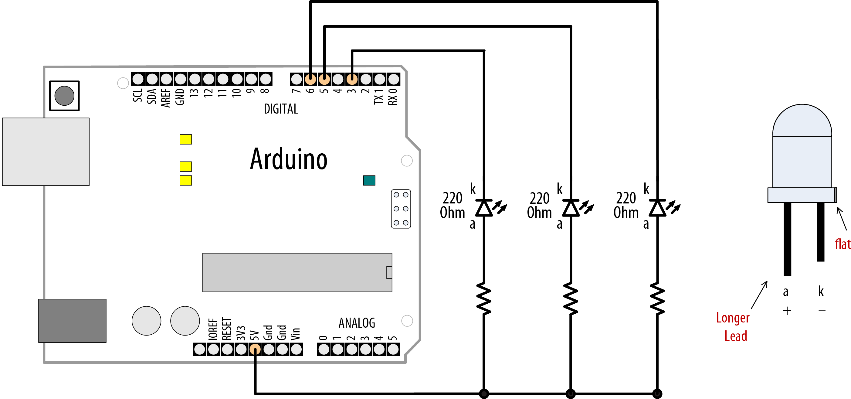
An LED is a semiconductor device (diode) with two leads, an anode and a cathode. When the voltage on the anode is more positive than that on the cathode (by an amount called the forward voltage) the device emits light (photons). The anode is usually the longer lead, and there is often a flat spot on the housing to indicate the cathode (see Figure 7-2). The LED color and the exact value of the forward voltage depend on the construction of the diode.
A typical red LED has a forward voltage of around 1.8 volts. If the voltage on the anode is not 1.8 volts more positive than the cathode, no current will flow through the LED and no light will be produced. When the voltage on the anode becomes 1.8 volts more positive than that on the cathode, the LED “turns on” (conducts) and effectively becomes a short circuit. You must limit the current with a resistor, or the LED will (sooner or later) burn out. Recipe 7.1 shows you how to calculate values for current-limiting resistors.
You may need to consult an LED datasheet to select the correct LED for your application, particularly to determine values for forward voltage and maximum current. Tables 7-1 and 7-2 show the most important fields you should look for on an LED datasheet.
| Parameter | Symbol | Rating | Units | Comment |
|---|---|---|---|---|
|
Forward current |
IF |
25 |
mA |
The maximum continuous current for this LED |
|
Peak forward current (1/10 duty @ 1 kHz) |
IFP |
160 |
mA |
The maximum pulsed current (given here for a pulse that is 1/10 on and 9/10 off) |
| Parameter | Symbol | Rating | Units | Comment |
|---|---|---|---|---|
|
Luminous intensity |
IV |
2 |
mcd |
If = 2 mA – brightness with 2 mA current |
|
IV |
40 |
mcd |
If = 20 mA – brightness with 20 mA current |
|
|
Viewing angle |
120 |
degrees |
The beam angle |
|
|
Wavelength |
620 |
nm |
The dominant or peak wavelength (color) |
|
|
Forward voltage |
VF |
1.8 |
volts |
The voltage across the LED when on |
Arduino pins on Uno, Leonardo, and Mega boards can supply up to 40 mA of current. This is plenty for a typical medium-intensity LED, but not enough to drive the higher brightness LEDs or multiple LEDs connected to a single pin. Recipe 7.3 shows how to use a transistor to increase the current through the LED.
The 3.3 volt boards have a lower current capacity, check the datasheet for your board to ensure that you do not exceed the maximum ratings.
Multicolor LEDs consist of two or more LEDs in one physical package. These may have more than two leads to enable separate control of the different colors. There are many package variants, so you should check the datasheet for your LED to determine how to connect the leads.
Multiplexing
Applications that need to control many LEDs can use a technique called multiplexing. Multiplexing works by switching groups of LEDs (usually arranged in rows or columns) in sequence. Recipe 7.12 shows how 32 individual LEDs (eight LEDs per digit, including decimal point) with four digits can be driven with just 12 pins. Eight pins drive a digit segment for all the digits and four pins select which digit is active. Scanning through the digits quickly enough (at least 25 times per second) creates the impression that the lights remain on rather than pulsing, through the phenomenon of persistence of vision.
Charlieplexing uses multiplexing along with the fact that LEDs have polarity (they only illuminate when the anode is more positive than the cathode) to switch between two LEDs by reversing the polarity.
Maximum pin current
LEDs can draw more power than the Arduino chip is designed to handle. The datasheet gives the absolute maximum ratings for the Arduino Uno chip (ATmega328P) as 40 mA per pin. The chip is capable of sourcing and sinking 200 mA overall, so you must also ensure that the total current is less than this. For example, five pins providing a HIGH output (sourcing) and five LOW (sinking) with each pin at 40 mA. It is good practice to design your applications to operate well within the absolute maximum ratings for best reliability, so best to keep current at or below 30 mA to provide a large comfort margin. For hobby use where more pin current is wanted and reduced reliability is acceptable, you can drive a pin with up to 40 mA as long as the 200 mA source and 200 mA sink limits per chip are not exceeded.
See the discussion section of Recipe 7.3 for a tip on how to get increased current without using external transistors.
Note
The datasheet refers to 40 mA as the absolute maximum rating and some engineers may be hesitant to operate anywhere near this value. However, the 40 mA figure is already de-rated by Atmel and they say the pins can safely handle this current. Recipes that follow refer to the 40 mA maximum rating; however, if you are building anything where reliability is important, de-rating this to 30 mA to provide an added comfort margin is prudent. But bear in mind that 3.3 volt boards and even some 5 volt boards have a lower rating: the Uno WiFi Rev 2 board is rated at 20mA, the Zero at 7mA. If you use a different board check the datasheet.
7.1 Connecting and Using LEDs
Problem
You want to control one or more LEDs and select the correct current-limiting resistor so that you do not damage the LEDs.
Solution
Turning an LED on and off is easy to do with Arduino, and some of the recipes in previous chapters have included this capability (see Recipe 5.1 for an example that controls the built-in LED on pin 13). The recipe here provides guidance on choosing and using external LEDs. Figure 7-2 shows the wiring for three LEDs, but you can run this sketch with just one or two.

Connecting external LEDs
Note
The schematic symbol for the cathode (the negative pin) is k, not c. The schematic symbol c is used for a capacitor.
The following sketch lights up three LEDs connected to pins 3, 5, and 6 in sequence for one second:
/*
 * LEDs sketch
 * Blink three LEDs each connected to a different digital pin
 */

const int firstLedPin  = 3; // choose the pin for each of the LEDs
const int secondLedPin = 5;
const int thirdLedPin  = 6;

void setup()
{
  pinMode(firstLedPin, OUTPUT);  // declare LED pins as output
  pinMode(secondLedPin, OUTPUT); // declare LED pins as output
  pinMode(thirdLedPin, OUTPUT);  // declare LED pins as output
}

void loop()
{
  // flash each of the LEDs for 1000 milliseconds (1 second)
  blinkLED(firstLedPin,  1000);
  blinkLED(secondLedPin, 1000);
  blinkLED(thirdLedPin,  1000);
}


// blink the LED on the given pin for the duration in milliseconds
void blinkLED(int pin, int duration)
{
  digitalWrite(pin, HIGH);     // turn LED on
  delay(duration);
  digitalWrite(pin, LOW);      // turn LED off
  delay(duration);
}
The sketch sets the pins connected to LEDs as output in the setup function. The loop function calls blinkLED to flash the LED for each of the three pins. blinkLED sets the indicated pin HIGH for one second (1,000 milliseconds).
Discussion
Because the anodes are connected to Arduino pins and the cathodes are connected to ground, the LEDs will light when the pin goes HIGH and will be off when the pin is LOW. You can illuminate the LED when the pin is LOW by connecting the cathodes to the pins and the anodes to ground (the resistors can be used on either side of the LED).
Connecting external LEDs with the cathode connected to pins
When LEDs are connected with the anode connected to +5V, as shown in Figure 7-3, the LEDs light when the pin goes LOW (the visual effect would reverse—one of the LEDs would turn off for a second while the other two would be lit).
Note
LEDs require a series resistor to control the current or they can quickly burn out. External LEDs need to be connected through a series resistor on either the anode or the cathode.
A resistor in series with the LED is used to control the amount of current that will flow when the LED conducts. To calculate the resistor value, you need to know the input power supply voltage (VS, usually 5 volts), the LED forward voltage (VF), and the amount of current (I) that you want to flow through the LED.
The formula for the resistance in ohms (known as Ohm’s law) is
- R = (VS – VF) / I
For example, driving an LED with a forward voltage of 1.8 volts with 15 mA of current using an input supply voltage of 5 volts would use the following values:
- Vs = 5 (for a 5V Arduino board)
- Vf = 1.8 (the forward voltage of the LED)
- I = 0.015 (1 milliamp [mA] is one one-thousandth of an amp, so 15 mA is 0.015 amps)
The voltage across the LED when it is on (Vs – Vf) is 5 – 1.8, which is 3.2 volts.
Therefore, the calculation for the series resistor is 3.2 / 0.015, which is 213 ohms.
The value of 213 ohms is not a standard resistor value, so you can round this up to 220 ohms.
The resistor is shown in Figure 7-2 connected between the cathode and ground, but it can be connected to the other side of the LED instead (between the voltage supply and the anode).
Warning
Arduino Uno and Mega pins have a specified maximum current of 40 mA. If your LED needs more current than your board can supply, see Recipe 7.3.
See Also
7.2 Adjusting the Brightness of an LED
Problem
You want to control the intensity of one or more LEDs from your sketch.
Solution
Connect each LED to an analog (PWM) output. Use the wiring shown in Figure 7-2. The sketch will fade the LED(s) from off to maximum intensity and back to off, with each cycle taking around five seconds:
/*
 * LedBrightness sketch
 * controls the brightness of LEDs on analog output ports
 */

const int firstLed   = 3; // specify the pin for each of the LEDs
const int secondLed  = 5;
const int thirdLed   = 6;

int brightness = 0;
int increment  = 1;

void setup()
{
  // pins driven by analogWrite do not need to be declared as outputs
}

void loop()
{
  if(brightness > 255)
  {
    increment = -1; // count down after reaching 255
  }
  else if(brightness < 1)
  {
    increment =  1; // count up after dropping back down to 0
  }
  brightness = brightness + increment; // increment (or decrement sign is minus)

  // write the brightness value to the LEDs
  analogWrite(firstLed, brightness);
  analogWrite(secondLed, brightness);
  analogWrite(thirdLed, brightness );

  delay(10); // 10ms for each step change means 2.55 secs to fade up or down
}
Discussion
This uses the same wiring as the previous sketch, but here the pins are controlled using analogWrite instead of digitalWrite. analogWrite uses PWM to control the power to the LED; see this chapter’s introduction section for more on analog output.
The sketch fades the light level up and down by increasing (on fade up) or decreasing (on fade down) the value of the brightness variable in each pass through the loop. This value is given to the analogWrite function for the three connected LEDs. The minimum value for analogWrite is 0—this keeps the voltage on the pin at 0. The maximum value is 255 (5V on a 5V board, 3.3V on a 3.3V board).
Tip
It is good practice to restrict the range of values to the range of 0-255, values outside that range can give unexpected results. See Recipe 3.5.
When the brightness variable reaches the maximum value, it will start to decrease, because the sign of the increment is changed from +1 to –1 (adding –1 to a value is the same as subtracting 1 from that value).
See Also
This chapter’s introduction describes how Arduino analog output works.
Boards such as the Due, Zero and MKR1000 can have the PWM range to a maximum of 4095, although they all default to the standard 255. If you need to use this higher resolution you can set this using the analogWriteResolution function, see https://www.arduino.cc/reference/en/language/functions/zero-due-mkr-family/analogwriteresolution/.
7.3 Driving High-Power LEDs
Problem
You need to switch or control the intensity of LEDs that need more power than the Arduino pins can provide. Arduino Uno and Mega chips can only handle current up to 40 mA per pin.
Solution
Use a transistor to switch on and off the current flowing through the LEDs. Connect the LED as shown in Figure 7-4. You can use the same code as shown in Recipe 7.1 and Recipe 7.2 (just make sure the pins connected to the transistor base match the pin number used in your sketch).
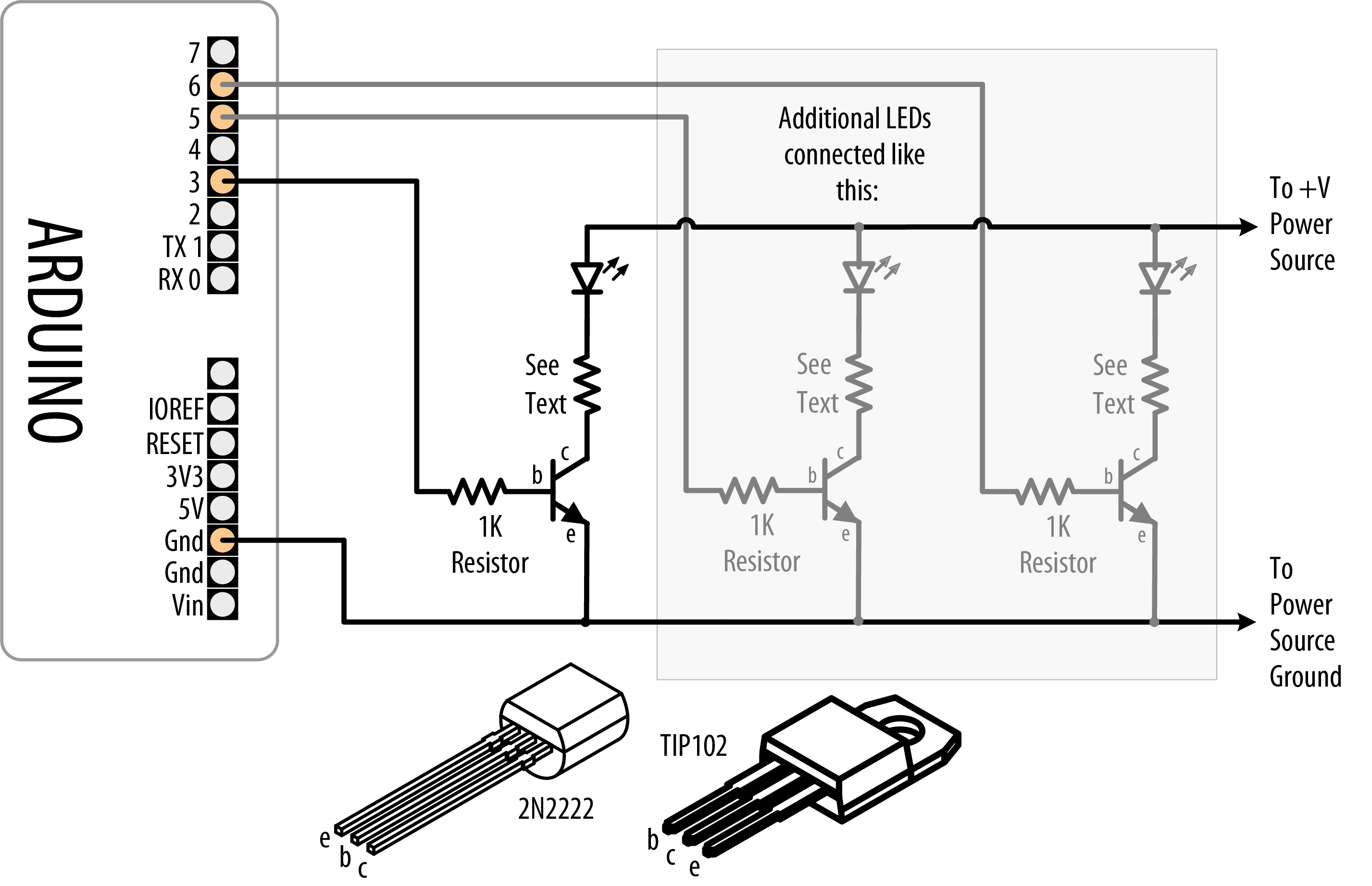
Using transistors to drive high-current LEDs
Discussion
Figure 7-4 has an arrow indicating a +V power source. This can be the Arduino +5V power pin, which can supply up to 400 mA or so if powered from USB. The available current when powered through the external power socket is dependent on the current rating and voltage of your DC power supply (the regulator dissipates excess voltage as heat—check that the on-board regulator, a 3-pin chip usually near the DC input socket, is not too hot to the touch). If more current is required than the Arduino +5V can provide, you need a power source separate from the Arduino to drive the LEDs. See Appendix C for information on using an external power supply.
Note
If you’re using an external power supply, remember to connect the ground of the external supply to the Arduino ground.
Current is allowed to flow from the collector to the emitter when the transistor is switched on. No significant current flows when the transistor is off. The Arduino can turn a transistor on by making the voltage on a pin HIGH with digitalWrite. A resistor is necessary between the pin and the transistor base to prevent too much current from flowing—1K ohms is a typical value (this provides 5 mA of current to the base of the transistor). See Appendix B for advice on how to read a datasheet and pick and use a transistor. You can also use specialized integrated circuits such as the ULN2003A for driving multiple outputs. These contain seven high-current (0.5 amp) output drivers.
The resistor used to limit the current flow through the LED is calculated using the technique given in Recipe 7.1, but you may need to take into account that the source voltage will be reduced slightly because of the small voltage drop through the transistor. This will usually be less than three-fourths of a volt (the actual value can be found by looking at collector-emitter saturation voltage; see Appendix B). High-current LEDs (1 watt or more) are best driven using a constant current source (a circuit that actively controls the current) to manage the current through the LED.
How to Exceed 40 mA per Pin on an ATmega chip
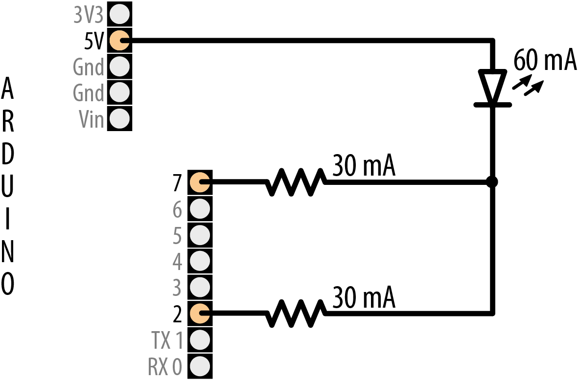
If your board uses an ATmega chip you can also connect multiple pins in parallel to increase current beyond the 40 mA per pin rating (see “Maximum pin current”).
Figure 7-5 shows how to connect an LED that can be driven with 60 mA through two pins. This shows the LED connecting the resistors to ground through pins 2 and 7—both pins need to be LOW for the full 60 mA to flow through the LED. The separate resistors are needed; don’t try to use a single resistor to connect the two pins.
How to exceed 40 mA per pin
This technique can also be used to source current. For example, flip the LED around—connect the lead that was going to the resistors (cathode) to GND and the other end (anode) to the resistors—and you illuminate the LED by setting both pins to HIGH.
It is best if you use pins that are not adjacent to minimize stress on the chip. This technique works for any pin using digitalWrite; it does not work with analogWrite—if you need more current for analog outputs (PWM), you will need to use transistors as explained above.
This technique is not reccommended for use on 32-bit boards.
See Also
Web reference for constant current drivers: http://www.neufeld.newton.ks.us/electronics/?p=475
7.4 Adjusting the Color of an LED
Problem
You want to control the color of an RGB LED under program control.
Solution
RGB LEDs have red, green, and blue elements in a single package, with either the anodes connected together (known as common anode) or the cathodes connected together (known as common cathode). Use the wiring in Figure 7-6 for common anode (the anodes are connected to +5 volts and the cathodes are connected to pins). Use Figure 7-2 if your RGB LEDs are common cathode.
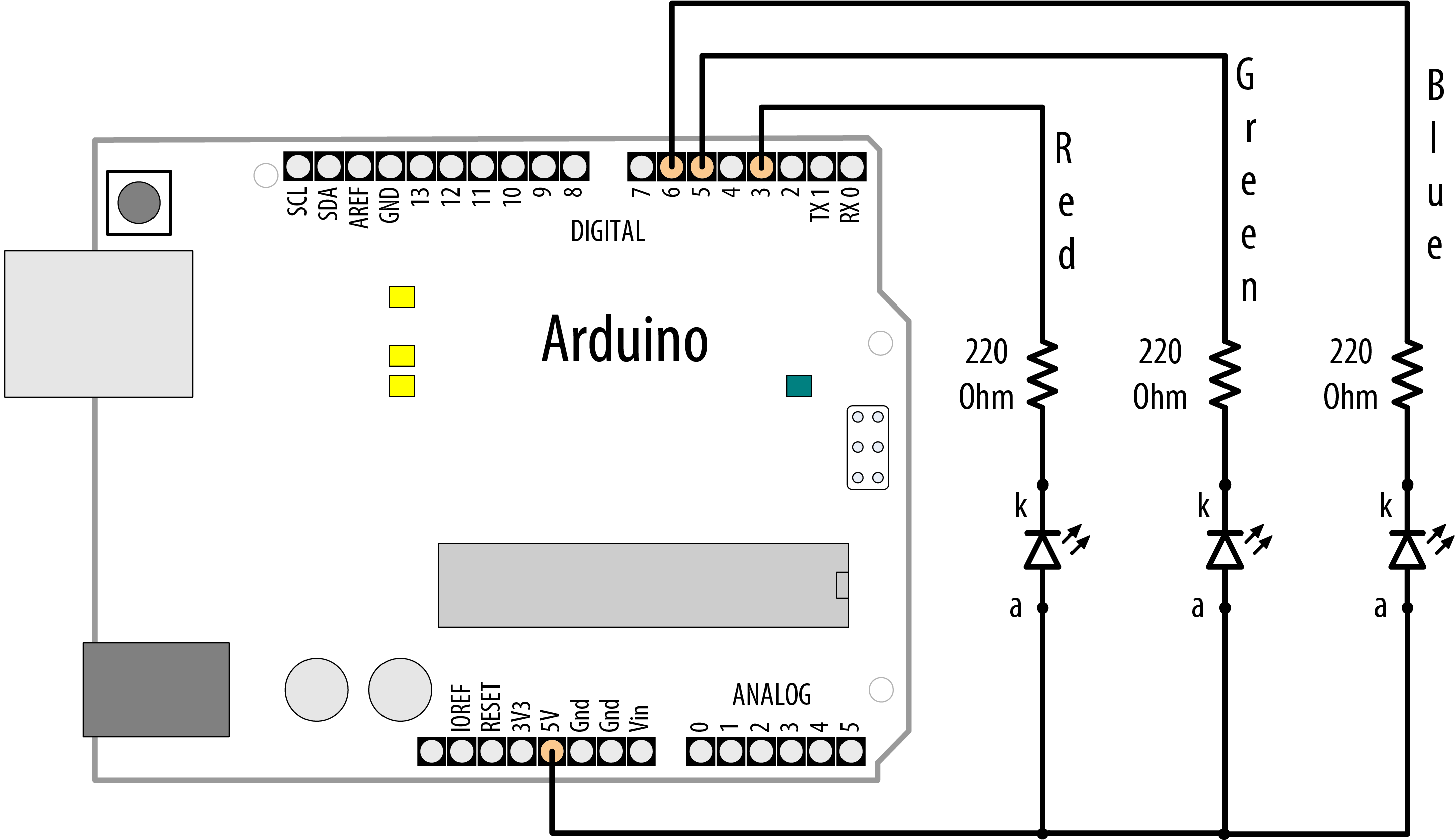
RGB connections (common anode)
This sketch continuously fades through the color spectrum by varying the intensity of the red, green, and blue elements:
/*
 * RGB_LEDs sketch
 * RGB LEDs driven from PWM output ports
*/

const int redPin   = 3;   // choose the pin for each of the LEDs
const int greenPin = 5;
const int bluePin  = 6;
const bool invert = true; // set true if common anode, false if common cathode

int color = 0; // a value from 0 to 255 representing the hue
int R, G, B;   // the Red Green and Blue color components

void setup()
{
  // pins driven by analogWrite do not need to be declared as outputs
}

void loop()
{
  int brightness = 255;        // 255 is maximum brightness

  hueToRGB(color, brightness); // call function to convert hue to RGB

  // write the RGB values to the pins
  analogWrite(redPin,   R);
  analogWrite(greenPin, G);
  analogWrite(bluePin,  B);

  color++; // increment the color
  if (color > 255)
    color = 0;
  delay(10);
}

// function to convert a color to its Red, Green, and Blue components.
//
void hueToRGB(int hue, int brightness)
{
  unsigned int scaledHue = (hue * 6);

  // segment 0 to 5 around the color wheel
  unsigned int segment = scaledHue / 256;

  // position within the segment
  unsigned int segmentOffset = scaledHue - (segment * 256);

  unsigned int complement = 0;
  unsigned int prev = (brightness * ( 255 -  segmentOffset)) / 256;
  unsigned int next = (brightness *  segmentOffset) / 256;
  if (invert)
  {
    brightness = 255 - brightness;
    complement = 255;
    prev = 255 - prev;
    next = 255 - next;
  }

  switch (segment) {
    case 0:    // red
      R = brightness;
      G = next;
      B = complement;
      break;
    case 1:    // yellow
      R = prev;
      G = brightness;
      B = complement;
      break;
    case 2:    // green
      R = complement;
      G = brightness;
      B = next;
      break;
    case 3:    // cyan
      R = complement;
      G = prev;
      B = brightness;
      break;
    case 4:    // blue
      R = next;
      G = complement;
      B = brightness;
      break;
    case 5:    // magenta
    default:
      R = brightness;
      G = complement;
      B = prev;
      break;
  }
}
Discussion
The color of an RGB LED is determined by the relative intensity of its red, green, and blue elements. The core function in the sketch (hueToRGB) handles the conversion of a hue value ranging from 0 to 255 into a corresponding color ranging from red to blue. The spectrum of visible colors is often represented using a color wheel consisting of the primary and secondary colors with their intermediate gradients. The spokes of the color wheel representing the six primary and secondary colors are handled by six case statements. The code in a case statement is executed if the segment variable matches the case number, and if so, the RGB values are set as appropriate for each. Segment 0 is red, segment 1 is yellow, segment 2 is green, and so on.
If you also want to adjust the brightness, you can reduce the value of the brightness variable. The following shows how to adjust the brightness with a variable resistor or sensor connected as shown in Figure 7-14 or Figure 7-18:
int brightness = map(analogRead(A0),0,1023,0,255); // get brightness from sensor
The brightness variable will range in value from 0 to 255 as the analog input ranges from 0 to 1,023, causing the LED to increase brightness as the value increases.
See Also
7.5 Controlling lots of color LEDs
Problem
You want to control the color of many LEDs using a single pin
Solution
This recipe show how to use smart RGB LEDS with a tiny controller built into each LED that enables many LEDS to be controlled from a single digital pin. This sketch uses the Adafruit Neopixels library (installed using the Arduino library manager) to change LED colors based on readings from an analog pin. Figure 7-7 shows the connection for a NeoPixel ring and a potentiometer to control the color.
/*
 * SimplePixel sketch
 * LED color changes with sensor value
 */

#include <Adafruit_NeoPixel.h>

const int sensorPin = A0; // analog pin for sensor
const int ledPin = 6;     // the pin the LED strip is connected to
const int count  = 8;     // how many LEDs in the strip

// declare led strip
Adafruit_NeoPixel leds = Adafruit_NeoPixel(count, ledPin, NEO_GRB + NEO_KHZ800);

void setup()
{
  leds.begin(); // initialise led strip
  for (int i = 0; i < count; i++) {
    leds.setPixelColor(i, leds.Color(0,0,0)); // turn each LEDs off
  }
  leds.show();  // refresh the strip with the new pixel values (all off)
}

void loop()
{
  static unsigned int last_reading = -1;

  int reading =  analogRead(sensorPin);
  if (reading != last_reading) { // If the value has changed

    // Map the analog reading to the color range of the NeoPixel
    unsigned int mappedSensorReading = map(reading, 0, 1023, 0, 65535);

    // Update the pixels with a slight delay to create a sweeping effect
    for (int i = 0; i < count; i++) {
      leds.setPixelColor(i, leds.gamma32(leds.ColorHSV(mappedSensorReading, 255, 128)));
      leds.show();
      delay(25);
    }
    last_reading = reading;
  }
}
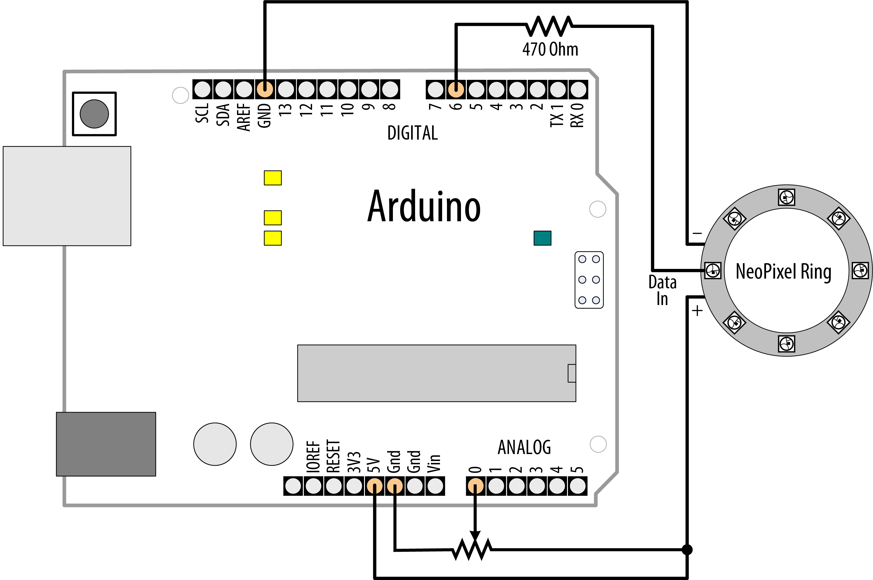
Connecting a NeoPixel ring
Warning
If you are using a 3.3V board, you will need to connect both the potentiometer and NeoPixel’s positive lead to 3.3V instead of 5V.
Discussion
This sketch drives a stick, strand, or a group of chained Adafruit Neopixels that has eight RGB LEDs. You can change the variable numOfLeds if you connect a different number of LEDs but bear in mind that each LED could consume up to 60mA (if you set to white at full brightness). A USB port can power up to eight, but above that you will need to attach the strips power connectors to a higher current 5V power supply, but you must connect the power supply’s ground to Arduino ground. If you are using a 3.3V board, you should not power the NeoPixels with more than 3.7V (such as from a lithium ion polymer battery), because NeoPixels require a data signal that’s close to their supply voltage. When using an external power supply, you should also connect a 1000 uf capacitor between the positive and negative supply pins to protect the pixels (check the polarity on the capacitor and make sure you are connecting it correctly).
The leds variable is declared with this line of code:
Adafruit_NeoPixel leds = Adafruit_NeoPixel(count, ledPin, NEO_GRB + NEO_KHZ800);
This creates the memory structure to store the color of each LED and communicate with the strip. You specify the number of LEDs in the strip (count), the Arduino pin the data line is connected to (ledPin), and the type of LED strip you are using (in this case: NEO_GRB+NEO_KHZ800). You will need to check the documentation for the library and your strip to see if you need a different setting, but you won’t do any harm to try all the options listed with the library to find one that works.
To set the color of an individual LED you use the led.setPixelColor method. You to specify the number of the LED (starting at 0 for the first one), and the desired color. To transfer data to the LEDs you need to call led.show. You can alter multiple LEDs values before calling led.show, to make them change together. Values not altered will remain at their previous settings. When you create the Adafruit_NeoPixel object, all the values are initialised to 0.
The NeoPixel library includes its own function for converting a hue to an RGB value, ColorHSV. The first argument is the hue, the second is the color saturation, and the third is brightness. The gamma32 function performs a conversion on the output of ColorHSV to compensate between the way that computers represent colors and the way that humans perceive them.
Each LED ‘pixel’ has connections for data input and output, power and ground. Arduino drives the data input of the first pixel, the data output of which is connected to the data input of the next in the chain. You can buy individual pixels or strips that come pre-connected.
If your strip is not supported by the Adafruit Library
Early LED strips used the WS2811 chip. There have been various other versions since: WS2812, WS2812B and APA102 for example. If your LEDs are not supported by the Adafruit library then try Fast LED library
The Arduino-compatible Teensy 3.x and higher (https://www.pjrc.com/teensy/) can control 8 strips on different pins and uses a combination of high speed hardware and software to enable very high quality animation.
The leds are available individually, but also on flexible strips in rolls, at different spacings (specified in leds/meter or foot). Adafruit produces a wide range of pcb form factors including circles of leds, short strips, and panels under the brand name NeoPixel.
See Also
Adafruit NeoPixel Uber Guide: https://learn.adafruit.com/adafruit-neopixel-uberguide/overview
Teensy library, which also has some good pictures of wiring for power supplies with large numbers of LEDs, and a processing programme that extracts the data from video for you to add to code to display the video on the strands.
7.6 Sequencing Multiple LEDs: Creating a Bar Graph
Problem
You want an LED bar graph that lights LEDs in proportion to a value in your sketch or a value read from a sensor.
Solution
You can connect the LEDs as shown in Figure 7-2 (using additional pins if you want more LEDs). Figure 7-8 shows six LEDs connected on consecutive pins.
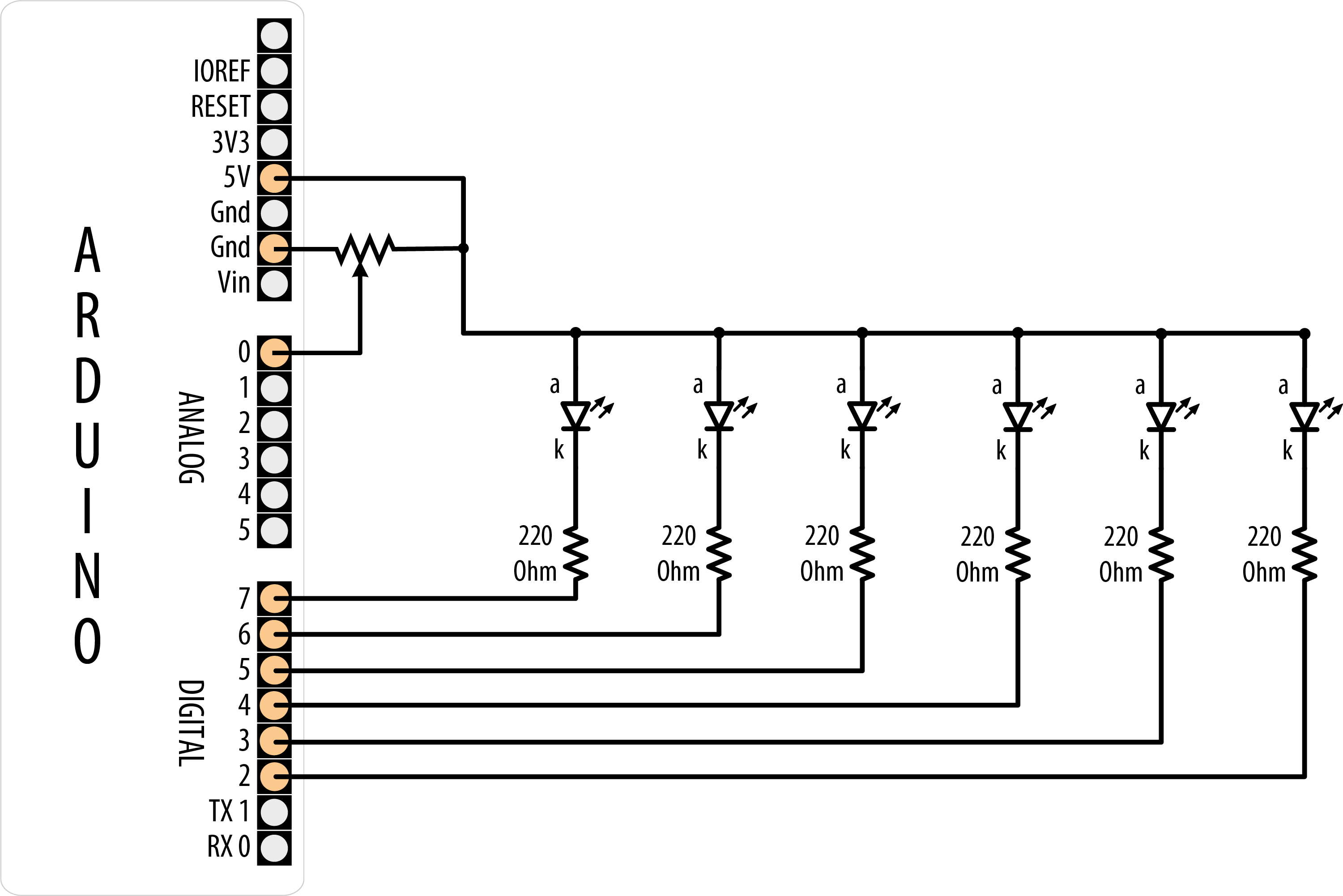
Six LEDs with cathodes connected to Arduino pins
The following sketch turns on a series of LEDs, with the number being proportional to the value of a sensor connected to an analog input port (see Figure 7-14 or Figure 7-18 to see how a sensor is connected):
/*
 * Bargraph sketch
 *
 * Turns on a series of LEDs proportional to a value of an analog sensor.
 * Six LEDs are controlled but you can change the number of LEDs by changing
 * the value of NbrLEDs and adding the pins to the ledPins array
 */

const int NbrLEDs = 6;
const int ledPins[] = { 2, 3, 4, 5, 6, 7 };
const int analogInPin = A0; // Analog input pin connected to variable resistor

// Swap values of the following two #defines if cathodes are connected to Gnd
#define LED_ON  LOW
#define LED_OFF HIGH

int sensorValue = 0;  // value read from the sensor
int ledLevel = 0;     // sensor value converted into LED 'bars'

void setup()
{
  for (int led = 0; led < NbrLEDs; led++)
  {
    pinMode(ledPins[led], OUTPUT);  // make all the LED pins outputs
  }
}

void loop()
{
  sensorValue = analogRead(analogInPin);             // read the analog in value
  ledLevel = map(sensorValue, 10, 1023, 0, NbrLEDs); // map to the number of LEDs
  for (int led = 0; led < NbrLEDs; led++)
  {
    if (led < ledLevel) {
      digitalWrite(ledPins[led], LED_ON);  // turn on pins below the level
    }
    else {
      digitalWrite(ledPins[led], LED_OFF); // turn off pins higher than the level
    }
  }
}
Discussion
The pins connected to LEDs are held in the array ledPins. To change the number of LEDs, you can add (or remove) elements from this array, but make sure the variable NbrLEDs is the same as the number of elements (which should be the same as the number of pins). You can have the compiler calculate the value of NbrLEDs for you by replacing this line:
const int NbrLEDs = 6;
with this line:
const int NbrLEDs = sizeof(ledPins) / sizeof(ledPins[0]);
The sizeof function returns the size (number of bytes) of a variable—in this case, the number of bytes in the ledPins array. Because it is an array of integers (with two bytes per element), the total number of bytes in the array is divided by the size of one element (sizeof(ledPins[0])) and this gives the number of elements.
The Arduino map function is used to calculate the number of LEDs that should be lit as a proportion of the sensor value. The code loops through each LED, turning it on if the proportional value of the sensor is greater than the LED number. For example, if the sensor value is below 10, no pins are lit; if the sensor is at half value, half are lit. In an ideal world, a potentiometer at its lowest setting will return zero, but it’s likely to drift in the real world. When the sensor is at maximum value, all the LEDs are lit. If you find that the last LED flickers when the potentiometer is at its maximum value, try lowering the second argument to map from 1023 to 1000 or so.
Figure 7-8 shows all the anodes connected together (known as common anode) and the cathodes connected to the pins; the pins need to be LOW for the LED to light. If the LEDs have the anodes connected to pins (as shown in Figure 7-2) and the cathodes are connected together (known as common cathode), the LED is lit when the pin goes HIGH. The sketch in this recipe uses the constant names LED_ON and LED_OFF to make it easy to select common anode or common cathode connections. To change the sketch for common cathode connection, swap the values of these constants as follows:
const bool LED_ON = HIGH;  // HIGH is on when using common cathode connection
const bool LED_OFF = LOW;
You may want to slow down the decay (rate of change) in the lights; for example, to emulate the movement of the indicator of a sound volume meter. Here is a variation on the sketch that slowly decays the LED bars when the level drops:
/*
 *  LED bar graph - decay version
 */

const int ledPins[] = {2, 3, 4, 5, 6, 7};
const int NbrLEDs = sizeof(ledPins) / sizeof(ledPins[0]);
const int analogInPin = A0; // Analog input pin connected to variable resistor
const int decay = 10;       // increasing this reduces decay rate of storedValue

// Swap values of the following two #defines if cathodes are connected to Gnd
#define LED_ON  LOW
#define LED_OFF HIGH

// the stored (decaying) sensor value
int storedValue = 0;

void setup()
{
  for (int led = 0; led < NbrLEDs; led++)
  {
    pinMode(ledPins[led], OUTPUT);  // make all the LED pins outputs
  }
}

void loop()
{
  int sensorValue = analogRead(analogInPin);             // read the analog in value
  storedValue = max(sensorValue, storedValue);       // use sensor value if higher
  int ledLevel = map(storedValue, 10, 1023, 0, NbrLEDs); // map to number of LEDs

  for (int led = 0; led < NbrLEDs; led++)
  {
    if (led < ledLevel ) {
      digitalWrite(ledPins[led], LED_ON);  // turn on pins less than the level
    }
    else {
      digitalWrite(ledPins[led], LED_OFF);   // turn off pins higher than the level
    }
  }
  storedValue = storedValue - decay;     // decay the value
  delay(10);                             // wait 10 ms before next loop
}
The decay is handled by the line that uses the max function. This returns either the sensor value or the stored decayed value, whichever is higher. If the sensor is higher than the decayed value, this is saved in storedValue. Otherwise, the level of storedValue is reduced by the constant decay each time through the loop (set to 10 milliseconds by the delay function). Increasing the value of the decay constant will reduce the time for the LEDs to fade to all off.
You could implement this bar graph using Neopixels, as mentioned in the previous recipe. The code for this would be
/*
 * PixelBarGraph.ino
 * Sensor value determines how many LEDs to light
 */

#include <Adafruit_NeoPixel.h>

const int sensorPin = A0; // analog pin for sensor

const int ledsPin = 2;   // the pin the LED strip is connected to
const int numOfLeds = 16; // how many LEDs in the strip

//used to automatically map sensor values
const int minReading = 0;
const int maxReading = 1023;

//declare led strip
Adafruit_NeoPixel leds = Adafruit_NeoPixel(numOfLeds, ledsPin, NEO_GRB + NEO_KHZ800);

void setup()
{
  leds.begin();   //initialise led strip
  leds.setBrightness(25);
}

void loop()
{
  int sensorReading =  analogRead(A0);
  int nbrLedsToLight = map(sensorReading, minReading, maxReading, 0, numOfLeds);

  for (int i = 0; i < numOfLeds; i++)
  {
    if ( i < nbrLedsToLight)
      leds.setPixelColor(i, leds.Color(0, 0, 255)); // blue
    else
      leds.setPixelColor(i, leds.Color(0, 255, 0)); // green
  }
  leds.show();
}
See Also
Recipe 3.6 explains the max function.
Recipe 5.6 has more on reading a sensor with the analogRead function.
Recipe 5.7 describes the map function.
See Recipes 12.2 and 12.1 if you need greater precision in your decay times. The total time through the loop is actually greater than 10 milliseconds because it takes an additional millisecond or so to execute the rest of the loop code.
7.7 Sequencing Multiple LEDs: Making a Chase Sequence
Problem
You want to light LEDs in a “chasing lights” sequence. This sequence was used in special effects on the TV shows Knight Rider and Battlestar Galactica, both created by Glen A. Larson, so this effect is also called a Larson Scanner.
Solution
You can use the same connection as shown in Figure 7-8:
/* Chaser
 */

const int NbrLEDs = 6;
const int ledPins[] = {2, 3, 4, 5, 6, 7};
const int wait_time = 30;

// Swap values of the following two #defines if cathodes are connected to Gnd
#define LED_ON  LOW
#define LED_OFF HIGH

void setup()
{
  for (int led = 0; led < NbrLEDs; led++)
  {
    pinMode(ledPins[led], OUTPUT);
  }
}

void loop()
{
  for (int led = 0; led < NbrLEDs - 1; led++)
  {
    digitalWrite(ledPins[led], LED_ON);
    delay(wait_time);
    digitalWrite(ledPins[led + 1], LED_ON);
    delay(wait_time);
    digitalWrite(ledPins[led], LED_OFF);
    delay(wait_time * 2);
  }
  for (int led = NbrLEDs - 1; led > 0; led--) {
    digitalWrite(ledPins[led], LED_ON);
    delay(wait_time);
    digitalWrite(ledPins[led - 1], LED_ON);
    delay(wait_time);
    digitalWrite(ledPins[led], LED_OFF);
    delay(wait_time * 2);
  }
}
Discussion
This code is similar to the code in Recipe 7.6, except the pins are turned on and off in a fixed sequence rather than depending on a sensor level. There are two for loops; the first produces the left-to-right pattern by lighting up LEDs from left to right. This loop starts with the first (leftmost) LED and steps through adjacent LEDs until it reaches and illuminates the rightmost LED. The second for loop lights the LEDs from right to left by starting at the rightmost LED and decrementing (decreasing by one) the LED that is lit until it gets to the first (rightmost) LED. The delay period is set by the wait variable and can be chosen to provide the most pleasing appearance.
7.8 Controlling an LED Matrix Using Multiplexing
Problem
You have a matrix of LEDs and want to minimize the number of Arduino pins needed to turn LEDs on and off.
Solution
Warning
This is a relatively power-hungry solution, and is only suitable for the Arduino Uno and other boards based on the ATmega328. The Uno WiFi Rev2 and Nano Every, as well as most (if not all) 32-bit boards cannot safely deliver enough current to drive all these LEDs. See Recipe 7.10 or Recipe 7.14 for a suitable Solution.
This sketch uses an LED matrix of 64 LEDs, with anodes connected in rows and cathodes in columns (as in the Jameco 2132349). Figure 7-9 shows the connections. (Dual-color LED displays may be easier to obtain, and you can drive just one of the colors if that is all you need.)
/*
 * matrixMpx sketch
 *
 * Sequence LEDs starting from first column and row until all LEDS are lit
 * Multiplexing is used to control 64 LEDs with 16 pins
 */

const int columnPins[] = {2, 3, 4, 5, 6, 7, 8, 9};
const int rowPins[]    = {10,11,12,A1,A2,A3,A4,A5};

int pixel       = 0; // 0 to 63 LEDs in the matrix
int columnLevel = 0; // pixel value converted into LED column
int rowLevel    = 0; // pixel value converted into LED row

void setup()
{
  for (int i = 0; i < 8; i++)
  {
    pinMode(columnPins[i], OUTPUT);  // make all the LED pins outputs
    pinMode(rowPins[i], OUTPUT);
  }
}

void loop()
{
  pixel = pixel + 1;
  if(pixel > 63)
     pixel = 0;

  columnLevel = pixel / 8;  // map to the number of columns
  rowLevel = pixel % 8;     // get the fractional value

  for (int column = 0; column < 8; column++)
  {
    digitalWrite(columnPins[column], LOW);     // connect this column to GND
    for(int row = 0; row < 8; row++)
    {
      if (columnLevel > column)
      {
        digitalWrite(rowPins[row], HIGH);  // connect all LEDs in row to + voltage
      }
      else if (columnLevel == column && rowLevel >= row)
      {
          digitalWrite(rowPins[row], HIGH);
      }
      else
      {
        digitalWrite(columnPins[column], LOW); // turn off all LEDs in this row
      }
      delayMicroseconds(300);    // delay gives frame time of 20ms for 64 LEDs
      digitalWrite(rowPins[row], LOW);  // turn off LED
    }

    // disconnect this column from Ground
    digitalWrite(columnPins[column], HIGH);
  }
}

An LED matrix connected to 16 digital pins
Warning
The wiring shown in this Recipe is based on Jameco part number 2132349, which represents a common form factor for this kind of array. But LED matrix displays do not have a standard pinout, so you must check the datasheet for your display. Wire the rows of anodes and columns of cathodes as shown in Figure 7-16 or Figure 7-17, but use the LED pin numbers shown in your datasheet.
The pins shown in Figure 7-9 show the logical arrangement of the pins as they relate to columns and rows. The numbers of the pins in the diagram correspond to the physical layout. Generally, the pin numbering follows a U-shaped pattern starting in the top left (1-8 from the top of the left column of pins to the bottom; 9-16 from the bottom of the right column of pins to the top). The trick is orienting the part so that pin 1 is in the upper left. You will need to look for an indentation, often in the shape of a small dot, that indicates which pin is 1. It is likely to be on the side, directly on the casing of the component. When in doubt, check the datasheet.
Discussion
The resistor’s value must be chosen to ensure that the maximum current through a pin does not exceed 40 mA on the Arduino Uno (and other boards based on the ATmega328; do not use this Solution with a 3.3V board or any board that cannot handle 40 mA per pin). Because the current for up to eight LEDs can flow through each column pin, the maximum current for each LED must be one-eighth of 40 mA, or 5 mA. Each LED in a typical small red matrix has a forward voltage of around 1.8 volts. Calculating the resistor that results in 5 mA with a forward voltage of 1.8 volts gives a value of 680 ohms. Check your datasheet to find the forward voltage of the matrix you want to use. Each column of the matrix is connected through the series resistor to a digital pin. When the column pin goes low and a row pin goes high, the corresponding LED will light. For all LEDs where the column pin is high or its row pin is low, no current will flow through the LED and it will not light.
The for loop scans through each row and column and turns on sequential LEDs until all LEDs are lit. The loop starts with the first column and row and increments the row counter until all LEDs in that row are lit; it then moves to the next column, and so on, lighting another LED with each pass through the loop until all the LEDs are lit.
You can control the number of lit LEDs in proportion to the value from a sensor (see Recipe 5.6 for connecting a sensor to the analog port) by making the following changes to the sketch.
Comment out or remove these three lines from the beginning of the loop:
  pixel = pixel + 1;
  if(pixel > 63)
     pixel = 0;
Replace them with the following lines that read the value of a sensor on pin 0 and map this to a number of pixels ranging from 0 to 63:
  int sensorValue = analogRead(0);             // read the analog in value
  pixel = map(sensorValue, 0, 1023, 0, 63);    // map sensor value to pixel (LED)
You can test this with a variable resistor connected to analog input pin 0 connected as shown in Figure 5-7 in Chapter 5. The number of LEDs lit will be proportional to the value of the sensor.
You don’t have to light an entire row at once. The following sketch will light one LED at a time as it goes through the sequence:
/*
 * matrixMpx sketch, one at a time
 *
 * Sequence LEDs starting from first column and row, one at a time
 * Multiplexing is used to control 64 LEDs with 16 pins
 */

const int columnPins[] = {2, 3, 4, 5, 6, 7, 8, 9};
const int rowPins[]    = {10,11,12,A1,A2,A3,A4,A5};

int pixel = 0; // 0 to 63 LEDs in the matrix

void setup()
{
  for (int i = 0; i < 8; i++)
  {
    pinMode(columnPins[i], OUTPUT);  // make all the LED pins outputs
    pinMode(rowPins[i], OUTPUT);
    digitalWrite(columnPins[i], HIGH);
  }
}

void loop()
{
  pixel = pixel + 1;
  if(pixel > 63)
     pixel = 0;

  int column = pixel / 8;  // map to the number of columns
  int row = pixel % 8;     // get the fractional value

  digitalWrite(columnPins[column], LOW);  // Connect this column to GND
  digitalWrite(rowPins[row], HIGH);       // Take this row HIGH

  delay(125);  // pause briefly

  digitalWrite(rowPins[row], LOW);        // Take the row low
  digitalWrite(columnPins[column], HIGH); // Disconnect the column from GND

}
7.9 Displaying Images on an LED Matrix
Problem
You want to display one or more images on an LED matrix, perhaps creating an animation effect by quickly alternating multiple images.
Solution
This Solution can use the same wiring as in Recipe 7.8. The sketch creates the effect of a heart beating by briefly lighting LEDs arranged in the shape of a heart. A small heart followed by a larger heart is flashed for each heartbeat (the images look like Figure 7-10):
/*
 * matrixMpxAnimation sketch
 * animates two heart images to show a beating heart
 */

// the heart images are stored as bitmaps - each bit corresponds to an LED
// a 0 indicates the LED is off, 1 is on
byte bigHeart[] = {
  B01100110,
  B11111111,
  B11111111,
  B11111111,
  B01111110,
  B00111100,
  B00011000,
  B00000000};

byte smallHeart[] = {
  B00000000,
  B00000000,
  B00010100,
  B00111110,
  B00111110,
  B00011100,
  B00001000,
  B00000000};

const int columnPins[] = { 2, 3, 4, 5, 6, 7, 8, 9};
const int rowPins[]    = {10,11,12,A1,A2,A3,A4,A5};

void setup() {
  for (int i = 0; i < 8; i++)
  {
    pinMode(rowPins[i], OUTPUT);        // make all the LED pins outputs
    pinMode(columnPins[i], OUTPUT);
    digitalWrite(columnPins[i], HIGH);  // disconnect column pins from Ground
  }
}

void loop() {
  int pulseDelay = 800 ; // milliseconds to wait between beats

  show(smallHeart, 80);  // show the small heart image for 80ms
  show(bigHeart, 160);   // followed by the big heart for 160ms
  delay(pulseDelay);     // show nothing between beats
}

// Show a frame of an image stored in the array pointed to by the image
// parameter. The frame is repeated for the given duration in milliseconds.
void show(byte * image, unsigned long duration)
{
 unsigned long start = millis();            // begin timing the animation
 while (start + duration > millis())        // loop until the duration period has passed
  {
    for(int row = 0; row < 8; row++)
    {
      digitalWrite(rowPins[row], HIGH);          // connect row to +5 volts
      for(int column = 0; column < 8; column++)
      {
        bool pixel = bitRead(image[row],column);
        if(pixel == 1)
        {
          digitalWrite(columnPins[column], LOW);  // connect column to Gnd
        }
        delayMicroseconds(300);                   // a small delay for each LED
        digitalWrite(columnPins[column], HIGH);   // disconnect column from Gnd
      }
      digitalWrite(rowPins[row], LOW);            // disconnect LEDs
    }
  }
}
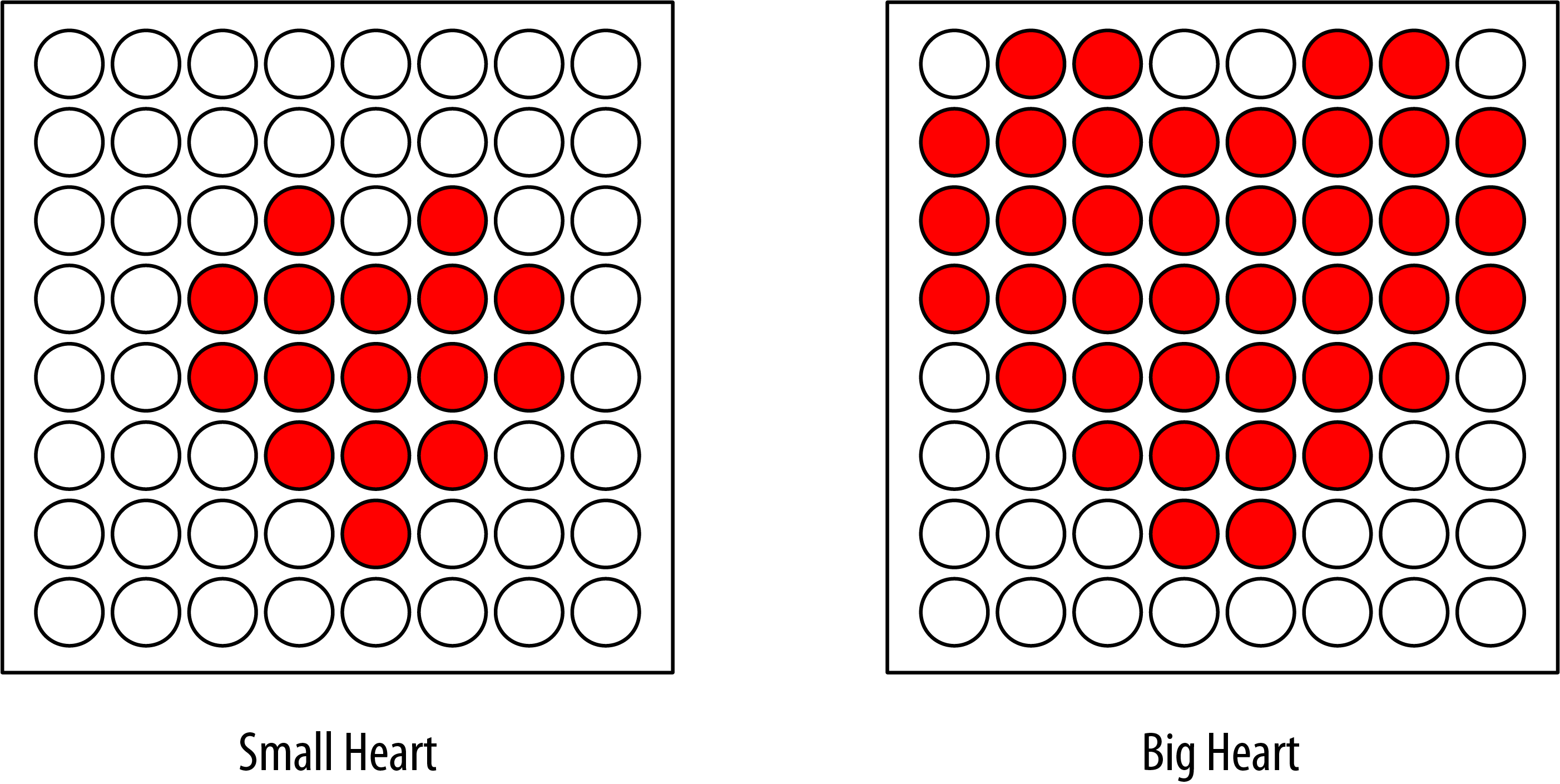
The two heart images displayed on each beat
Discussion
Columns and rows are multiplexed (switched) similar to Recipe 7.8, but here the value written to the LED is based on images stored in the bigHeart and smallHeart arrays. Each element in the array represents a pixel (a single LED) and each array row represents a row in the matrix. A row consists of eight bits represented using binary format (as designated by the capital B at the start of each row). A bit with a value of 1 indicates that the corresponding LED should be on; a 0 means off. The animation effect is created by rapidly switching between the arrays.
The loop function waits a short time (800 milliseconds) between beats and then calls the show function, first with the smallHeart array and then followed by the bigHeart array. The show function steps through each element in all the rows and columns, lighting the LED if the corresponding bit is 1. The bitRead function (see Recipe 2.20) is used to determine the value of each bit.
A short delay of 300 microseconds between each pixel allows the eye enough time to perceive the LED. The timing is chosen to allow each image to repeat quickly enough (50 times per second) so that blinking is not perceptible.
Here is a variation that changes the rate at which the heart beats, based on the value from a sensor. You can test this using a variable resistor connected to analog input pin 0, as shown in Recipe 5.6. Use the wiring and code shown earlier, except replace the loop function with this code:
void loop() {
  int sensorValue = analogRead(A0);                // read the analog in value
  int pulseRate =  map(sensorValue,0,1023,40,240); // convert to beats / minute
  int pulseDelay = (60000 / pulseRate);  // milliseconds to wait between beats

  show(smallHeart, 80);            // show the small heart image for 100 ms
  show(bigHeart, 160);             // followed by the big heart for 200ms
  delay(pulseDelay);               // show nothing between beats
}
This version calculates the delay between pulses using the map function (see Recipe 5.7) to convert the sensor value into beats per minute. The calculation does not account for the time it takes to display the heart, but you can subtract 240 milliseconds (80 ms plus 160 ms for the two images) if you want more accurate timing.
7.10 Controlling a Matrix of LEDs: Charlieplexing
Problem
You have a matrix of LEDs and you want to minimize the number of pins needed to turn any of them on and off.
Solution
Charlieplexing is a special kind of multiplexing that increases the number of LEDs that can be driven by a group of pins. This sketch sequences through six LEDs using just three pins. Figure 7-11 shows the connections (to calculate the correct resistor value for the LED connections, see Recipe 7.1):
/*
 * Charlieplexing sketch
 * light six LEDs in sequence that are connected to pins 2, 3, and 4
 */

int pins[] = {2,3,4};  // the pins that are connected to LEDs

// the next two lines calculate the number of pins and LEDs from the above array
const int NUMBER_OF_PINS = sizeof(pins)/ sizeof(pins[0]);
const int NUMBER_OF_LEDS = NUMBER_OF_PINS * (NUMBER_OF_PINS-1);

byte pairs[NUMBER_OF_LEDS/2][2] = { {2,1}, {1,0}, {2,0} }; // maps pins to LEDs

void setup()
{
   // nothing needed here
}

void loop(){
    for(int i=0; i < NUMBER_OF_LEDS; i++)
    {
       lightLed(i);  // light each LED in turn
       delay(1000);
    }
}

// this function lights the given LED, the first LED is 0
void lightLed(int led)
{
  // the following four lines convert LED number to pin numbers
  int indexA = pairs[led/2][0];
  int indexB = pairs[led/2][1];
  int pinA = pins[indexA];
  int pinB = pins[indexB];

  // turn off all pins not connected to the given LED
  for(int i=0; i < NUMBER_OF_PINS; i++)
  {
    if(pins[i] != pinA && pins[i] != pinB)
    {  // if this pin is not one of our pins
        pinMode(pins[i], INPUT);   // set the mode to input
        digitalWrite(pins[i],LOW); // make sure pull-up is off
    }
  }
  // now turn on the pins for the given LED
  pinMode(pinA, OUTPUT);
  pinMode(pinB, OUTPUT);
  if( led % 2 == 0)
  {
     digitalWrite(pinA,LOW);
     digitalWrite(pinB,HIGH);
  }
  else
  {
     digitalWrite(pinB,LOW);
     digitalWrite(pinA,HIGH);
  }
}
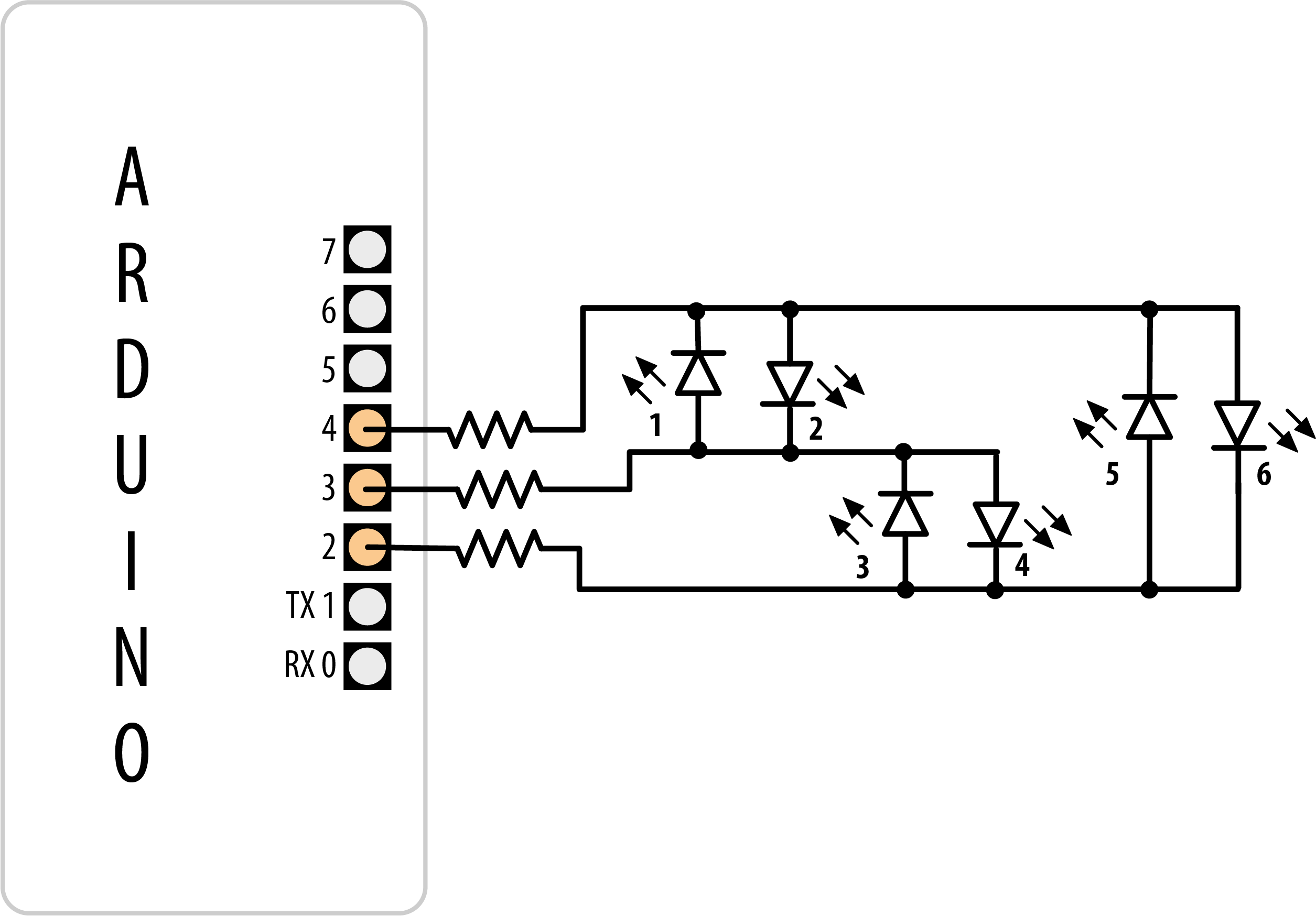
Six LEDs driven through three pins using Charlieplexing
Discussion
The term Charlieplexing comes from Charlie Allen (of Microchip Technology, Inc.), who published the method. The technique is based on the fact that LEDs only turn on when connected the “right way” around (with the anode more positive than the cathode). Here is the table showing the LED number (see Figure 7-9) that is lit for the valid combinations of the three pins. L is LOW, H is HIGH, and i is INPUT mode. Setting a pin in INPUT mode effectively disconnects it from the circuit:
  Pins       LEDs
4  3  2    1  2  3  4  5  6
L  L  L    0  0  0  0  0  0
L  H  i    1  0  0  0  0  0
H  L  i    0  1  0  0  0  0
i  L  H    0  0  1  0  0  0
i  H  L    0  0  0  1  0  0
L  i  H    0  0  0  0  1  0
H  i  L    0  0  0  0  0  1
You can double the number of LEDs to 12 using just one more pin. The first six LEDs are connected in the same way as in the preceding example; add the additional six LEDs so that the connections look like Figure 7-12.
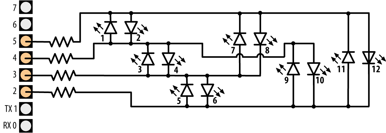
Charlieplexing using four pins to drive 12 LEDs
Modify the preceding sketch by adding the extra pin to the pins array:
byte pins[] = {2,3,4,5}; // the pins that are connected to LEDs
Add the extra entries to the pairs array so that it reads as follows:
byte pairs[NUMBER_OF_LEDS/2][2] = { {0,1}, {1,2}, {0,2}, {2,3}, {1,3}, {0,3} };
Everything else can remain the same, so the loop will sequence through all 12 LEDs because the code determines the number of LEDs from the number of entries in the pins array.
Because Charlieplexing works by controlling the Arduino pins so that only a single LED is turned on at a time, it is more complicated to create the impression of lighting multiple LEDs. But you can light multiple LEDs using a multiplexing technique modified for Charlieplexing.
This sketch creates a bar graph by lighting a sequence of LEDs based on the value of a sensor connected to analog pin 0:
byte pins[] = {2,3,4};
const int NUMBER_OF_PINS = sizeof(pins)/ sizeof(pins[0]);
const int NUMBER_OF_LEDS = NUMBER_OF_PINS * (NUMBER_OF_PINS-1);

byte pairs[NUMBER_OF_LEDS/2][2] = { {2,1}, {1,0}, {2,0} }; // maps pins to LEDs

int ledStates = 0; //holds states for up to 15 LEDs
int refreshedLed;  // the LED that gets refreshed

void setup()
{
   // nothing here
}

void loop()
{
const int analogInPin = 0; // Analog input pin connected to the variable resistor

  // here is the code from the bargraph recipe
  int sensorValue = analogRead(analogInPin);          // read the analog in value
  // map to the number of LEDs
  int ledLevel = map(sensorValue, 0, 1023, 0, NUMBER_OF_LEDS);
  for (int led = 0; led < NUMBER_OF_LEDS; led++)
  {
    if (led < ledLevel ) {
      setState(led, HIGH);     // turn on pins less than the level
    }
    else {
      setState(led, LOW);      // turn off pins higher than the level
    }
  }
  ledRefresh();

}

void setState( int led, bool state)
{
   bitWrite(ledStates,led, state);
}

void ledRefresh()
{
   // refresh a different LED each time this is called.
   if( refreshedLed++ > NUMBER_OF_LEDS) // increment to the next LED
      refreshedLed = 0; // repeat from the first LED if all have been refreshed

   if( bitRead(ledStates, refreshedLed ) == HIGH)
         lightLed( refreshedLed );
   else
       if(refreshedLed == 0) // Turn them all off if we pin 0 is off
         for(int i=0; i < NUMBER_OF_PINS; i++)
           digitalWrite(pins[i],LOW);
}

// this function is identical to the one from the sketch in the Solution
// it lights the given LED, the first LED is 0
void lightLed(int led)
{
  // the following four lines convert LED number to pin numbers
  int indexA = pairs[led/2][0];
  int indexB = pairs[led/2][1];
  int pinA = pins[indexA];
  int pinB = pins[indexB];

  // turn off all pins not connected to the given LED
  for(int i=0; i < NUMBER_OF_PINS; i++)
  {
    if(pins[i] != pinA && pins[i] != pinB)
    {  // if this pin is not one of our pins
        pinMode(pins[i], INPUT);   // set the mode to input
        digitalWrite(pins[i],LOW); // make sure pull-up is off
    }
  }
  // now turn on the pins for the given LED
  pinMode(pinA, OUTPUT);
  pinMode(pinB, OUTPUT);
  if( led % 2 == 0)
  {
     digitalWrite(pinA,LOW);
     digitalWrite(pinB,HIGH);
  }
  else
  {
     digitalWrite(pinB,LOW);
     digitalWrite(pinA,HIGH);
  }
}
This sketch uses the value of the bits in the variable ledStates to represent the state of the LEDs (0 if off, 1 if on). The refresh function checks each bit and lights the LEDs for each bit that is set to 1. The refresh function must be called quickly and repeatedly, or the LEDs will appear to blink.
Warning
Adding delays into your code can interfere with the persistence of vision effect that creates the illusion that hides the flashing of the LEDs.
You can use an interrupt to service the refresh function in the background (without needing to explicitly call the function in loop). Timer interrupts are covered in Chapter 18, but here is a preview of one approach for using an interrupt to service your LED refreshes. This uses a third-party library called FrequencyTimer2, available from the Library Manager to create the interrupt (for instructions on installing third-party libraries, see Recipe 16.2):
#include <FrequencyTimer2.h>  // include this library to handle the refresh

byte pins[] = {2,3,4};
const int NUMBER_OF_PINS = sizeof(pins)/ sizeof(pins[0]);
const int NUMBER_OF_LEDS = NUMBER_OF_PINS * (NUMBER_OF_PINS-1);

byte pairs[NUMBER_OF_LEDS/2][2] = { {2,1}, {1,0}, {2,0} };

int ledStates = 0; //holds states for up to 15 LEDs
int refreshedLed;  // the LED that gets refreshed

void setup()
{
  FrequencyTimer2::setPeriod(20000/NUMBER_OF_LEDS); // set the period
  // the next line tells FrequencyTimer2 the function to call (ledRefresh)
  FrequencyTimer2::setOnOverflow(ledRefresh);
  FrequencyTimer2::enable();
}

void loop()
{
const int analogInPin = 0; // Analog input pin connected to the variable resistor

  // here is the code from the bargraph recipe
  int sensorValue = analogRead(analogInPin);          // read the analog in value
  // map to the number of LEDs
  int ledLevel = map(sensorValue, 0, 1023, 0, NUMBER_OF_LEDS);
  for (int led = 0; led < NUMBER_OF_LEDS; led++)
  {
    if (led < ledLevel ) {
      setState(led, HIGH);     // turn on pins less than the level
    }
    else {
      setState(led, LOW);      // turn off pins higher than the level
    }
  }
   // the LED is no longer refreshed in loop, it's handled by FrequencyTimer2
}

// the remaining code is the same as the previous example
The FrequencyTimer2 library has the period set to 1,666 microseconds (20 ms divided by 12, the number of LEDs). The FrequencyTimer2setOnOverflow method gets the function to call (ledRefresh) each time the timer “triggers.” The FrequencyTimer2 library is compatible with a limited number of boards: Arduino Uno (and likely most ATmega328-based compatibles), the Arduino Mega, and several Teensy variants. See https://www.pjrc.com/teensy/td_libs_FrequencyTimer2.html for more details on the library.
See Also
Chapter 18 provides more information on timer interrupts.
7.11 Driving a 7-Segment LED Display
Problem
You want to display numerals using a 7-segment numeric display.
Solution
The following sketch displays numerals from 0 to 9 on a single-digit, 7-segment display. Figure 7-13 shows the connections for a common anode display. Your pin assignments may be different so check the datasheet for your display. If yours is a common cathode, connect the common cathode connection to GND. The output is produced by turning on combinations of segments that represent the numerals:
/*
 * SevenSegment sketch
 * Shows numerals ranging from 0 through 9 on a single-digit display
 * This example counts seconds from 0 to 9
 */

// bits representing segments A through G (and decimal point) for numerals 0-9
const byte numeral[10] = {
 //ABCDEFG+dp
  B11111100,  // 0
  B01100000,  // 1
  B11011010,  // 2
  B11110010,  // 3
  B01100110,  // 4
  B10110110,  // 5
  B00111110,  // 6
  B11100000,  // 7
  B11111110,  // 8
  B11100110,  // 9
};

// pins for decimal point and each segment
//                          dp,G,F,E,D,C,B,A
const int segmentPins[8] = { 5,8,9,7,6,4,3,2};

void setup()
{
  for(int i=0; i < 8; i++)
  {
    pinMode(segmentPins[i], OUTPUT); // set segment and DP pins to output
  }
}

void loop()
{
  for(int i=0; i <= 10; i++)
  {
    showDigit(i);
    delay(1000);
  }
  // the last value if i is 10 and this will turn the display off
  delay(2000);  // pause two seconds with the display off
}

// Displays a number from 0 through 9 on a 7-segment display
// any value not within the range of 0-9 turns the display off
void showDigit(int number)
{
  bool isBitSet;

  for(int segment = 1; segment < 8; segment++)
  {
    if( number < 0 || number > 9){
      isBitSet = 0;   // turn off all segments
    }
    else{
      // isBitSet will be true if given bit is 1
      isBitSet = bitRead(numeral[number], segment);
    }
    isBitSet = ! isBitSet; // remove this line if common cathode display
    digitalWrite(segmentPins[segment], isBitSet);
  }
}
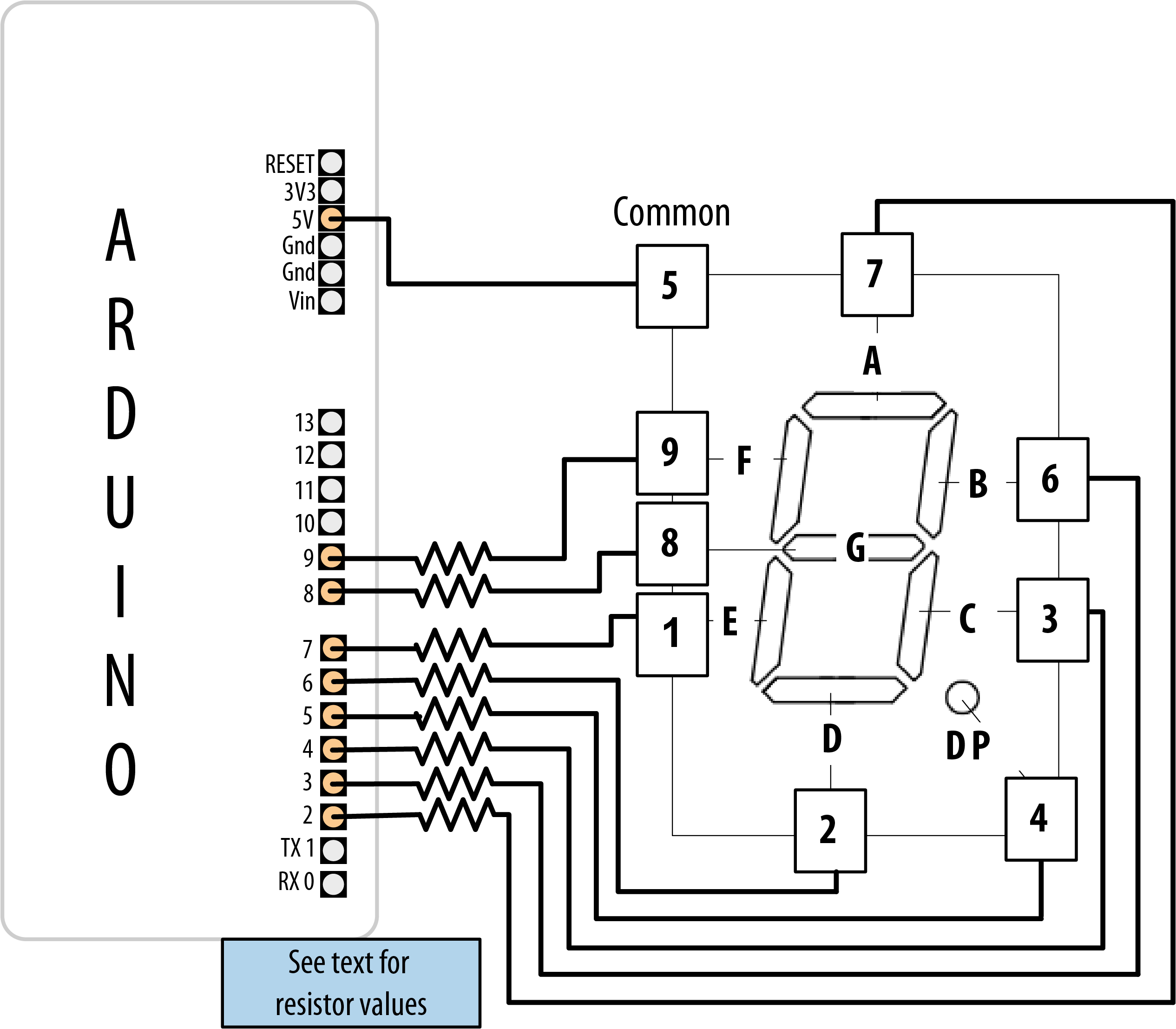
Connecting a 7-segment display
Discussion
The segments to be lit for each numeral are held in the array called numeral. There is one byte per numeral where each bit in the byte represents one of seven segments (or the decimal point).
The array called segmentPins holds the pins associated with each segment. The showDigit function checks that the number ranges from 0 to 9, and if valid, looks at each segment bit and turns on the segment if the bit is set (equal to 1). See Recipe 3.12 for more on the bitRead function.
As mentioned in Recipe 7.4, a pin is set HIGH when turning on a segment on a common cathode display, and it’s set LOW when turning on a segment on a common anode display. The code here is for a common anode display, so it inverts the value (sets 0 to 1 and 1 to 0) as follows:
isBitSet = ! isBitSet; // remove this line if common cathode display
The ! is the negation operator—see Recipe 2.20. If your display is a common cathode display (all the cathodes are connected together; see the datasheet if you are not sure), you can remove that line.
7.12 Driving Multidigit, 7-Segment LED Displays: Multiplexing
Problem
You want to display numbers using a 7-segment display that shows two or more digits.
Solution
Multidigit, 7-segment displays usually use multiplexing. In earlier recipes, multiplexed rows and columns of LEDs were connected together to form an array; here, corresponding segments from each digit are connected together (Figure 7-14 shows the connection for a Lite-On LTC-2623, but you will need to check the datasheet for your display if it’s different):
Note
The wiring diagram shown is for a Lite-On LTC-2623 display. If you are using a different display, you can use the same Arduino pins, but you’ll need to look up the corresponding pins on your display’s datasheet. The LTC-2623 is a common anode display. If yours is a common cathode, you’ll need to change two things: first, connect the transistors differently: connect all the emitters together and to ground, and each transistor’s collector to the corresponding pin on the display. Second, comment out or delete this line from the sketch:isBitSet = ! isBitSet;/*
* SevenSegmentMpx sketch
* Shows numbers ranging from 0 through 9999 on a four-digit display
* This example displays the value of a sensor connected to an analog input
*/
// bits representing segments A through G (and decimal point) for numerals 0-9
const int numeral[10] = {
//ABCDEFG /dp
B11111100, // 0
B01100000, // 1
B11011010, // 2
B11110010, // 3
B01100110, // 4
B10110110, // 5
B00111110, // 6
B11100000, // 7
B11111110, // 8
B11100110, // 9
};
// pins for decimal point and each segment
// dp,G,F,E,D,C,B,A
const int segmentPins[] = { 4, 7,8,6,5,3,2,9};
const int nbrDigits= 4; // the number of digits in the LED display
//dig 1 2 3 4
const int digitPins[nbrDigits] = { 10,11,12,13};
void setup()
{
for(int i=0; i < 8; i++)
pinMode(segmentPins[i], OUTPUT); // set segment and DP pins to output
for(int i=0; i < nbrDigits; i++)
pinMode(digitPins[i], OUTPUT);
}
void loop()
{
int value = analogRead(0);
showNumber(value);
}
void showNumber(int number)
{
if(number == 0)
showDigit( 0, nbrDigits-1) ; // display 0 in the rightmost digit
else
{
// display the value corresponding to each digit
// leftmost digit is 0, rightmost is one less than the number of places
for( int digit = nbrDigits-1; digit >= 0; digit--)
{
if(number > 0)
{
showDigit( number % 10, digit) ;
number = number / 10;
}
}
}
}
// Displays given number on a 7-segment display at the given digit position
void showDigit( int number, int digit)
{
digitalWrite( digitPins[digit], HIGH );
for(int segment = 1; segment < 8; segment++)
{
bool isBitSet = bitRead(numeral[number], segment);
// isBitSet will be true if given bit is 1
isBitSet = ! isBitSet; // remove this line if common cathode display
digitalWrite( segmentPins[segment], isBitSet);
}
delay(5);
digitalWrite( digitPins[digit], LOW );
}
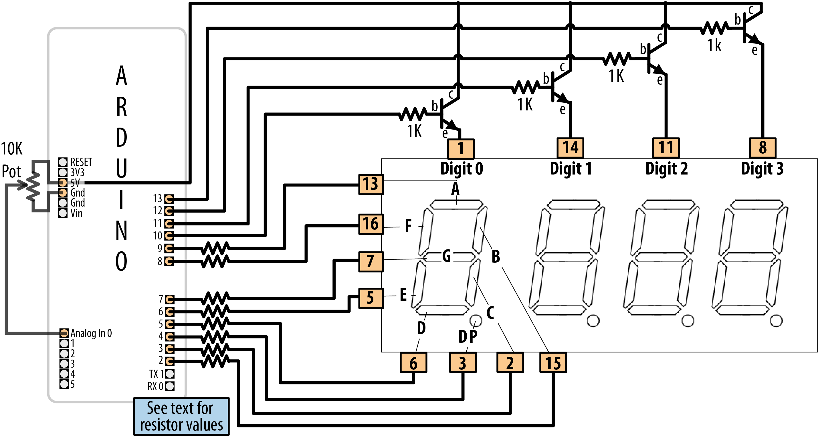
Connecting a multidigit, 7-segment display (LTC-2623)
Discussion
This sketch has a showDigit function similar to that discussed in Recipe 7.11. Here the function is given the numeral and the digit place. The logic to light the segments to correspond to the numeral is the same, but in addition, the code sets the pin corresponding to the digit place HIGH, so only that digit will be written (see the earlier multiplexing explanations).
7.13 Driving Multidigit, 7-Segment LED Displays with the Fewest Pins
Problem
You want to control multiple 7-segment displays, but you want to minimize the number of required Arduino pins.
Solution
This Solution uses an HT16K33-based breakout board to control four-digit common cathode displays, such as the LuckyLight KW4-56NXBA-P or the Betlux BL-Q56C-43. The HT16K33 provides a simpler solution than Recipe 7.12, because it handles multiplexing and digit decoding in hardware. You can obtain HT16K33-based boards from a variety of sources. Adafruit makes 7-Segment LED Matrix Backpack (part number 877) that is designed to work with the 4-digit 7 segment displays that they stock, but they also carry these boards with the displays included, and in a variety of colors (see https://www.adafruit.com/category/103).
This sketch will display a number between 0 and 9,999 (Figure 7-15 shows the connections):
/*
  HT16K33 seven segment display sketch
*/

#include <Wire.h>
#include <Adafruit_GFX.h>
#include "Adafruit_LEDBackpack.h"

Adafruit_7segment matrix = Adafruit_7segment();

const int numberOfDigits = 4; // change this to match the number of digits wired up
const int maxCount       = 9999;

int number = 0;

void setup()
{
  Serial.begin(9600);
  matrix.begin(0x70);     // Initialize the display
  matrix.println(number); // Send the number (0 initially) to the display
  matrix.writeDisplay();  // Update the display
}

void loop()
{
  // display a number from serial port terminated by end of line character
  if (Serial.available())
  {
    char ch  = Serial.read();
    if ( ch == '
')
    {
      if (number <= maxCount)
      {
        matrix.println(number);
        matrix.writeDisplay();
        number = 0; // Reset the number to 0
      }
    }
    else
      number = (number * 10) + ch - '0'; // see Chapter 4 for details
  }
}
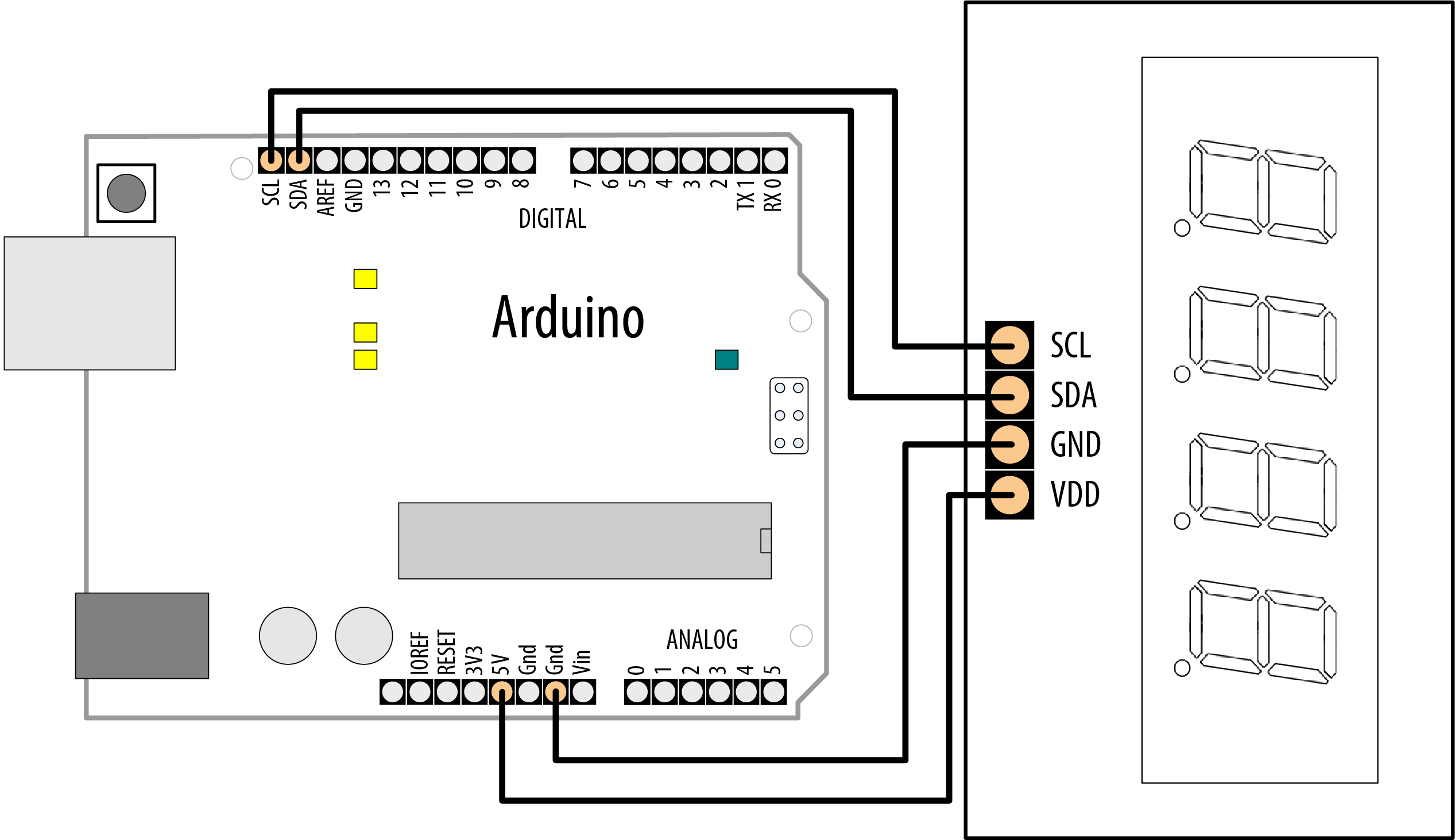
HT16K33 driving a multidigit common cathode 7-segment display
Solution
This recipe uses Arduino I2C communication to talk to the HT16K33 chip. The Adafruit_LEDBackpack library provides an interface to the hardware, via an instance of the Adafruit_7segment object (in this sketch, it’s called matrix). Chapter 13 covers I2C in more detail.
This sketch displays a number if up to four digits are received on the serial port—see Chapter 4 for an explanation of the serial code in loop. The matrix.println function sends values to the HT16K33, and the matrix.writeDisplay function updates the display with the latest value sent to it.
The breakout board uses a four-digit, 7-segment display, but if you buy a more generic HT16K33 breakout board (such as Adafruit part number 1427), you can use it with single- or dual-digit displays for up to eight digits. When combining multiple displays, each corresponding segment pin should be connected together. (Recipe 13.1 shows the connections for a common dual-digit display.) You will need to consult the datasheet for your segment display(s), as well as for whichever HT16K33 breakout you use.
7.14 Controlling an Array of LEDs by Using MAX72xx Shift Registers
Problem
You have an 8×8 array of LEDs to control, and you want to minimize the number of required Arduino pins.
Solution
As in Recipe 7.13, you can use a shift register to reduce the number of pins needed to control an LED matrix. This Solution uses the popular MAX7219 or MAX7221 LED driver chip to provide this capability. Connect your Arduino, matrix, and MAX72xx as shown in Figure 7-16.
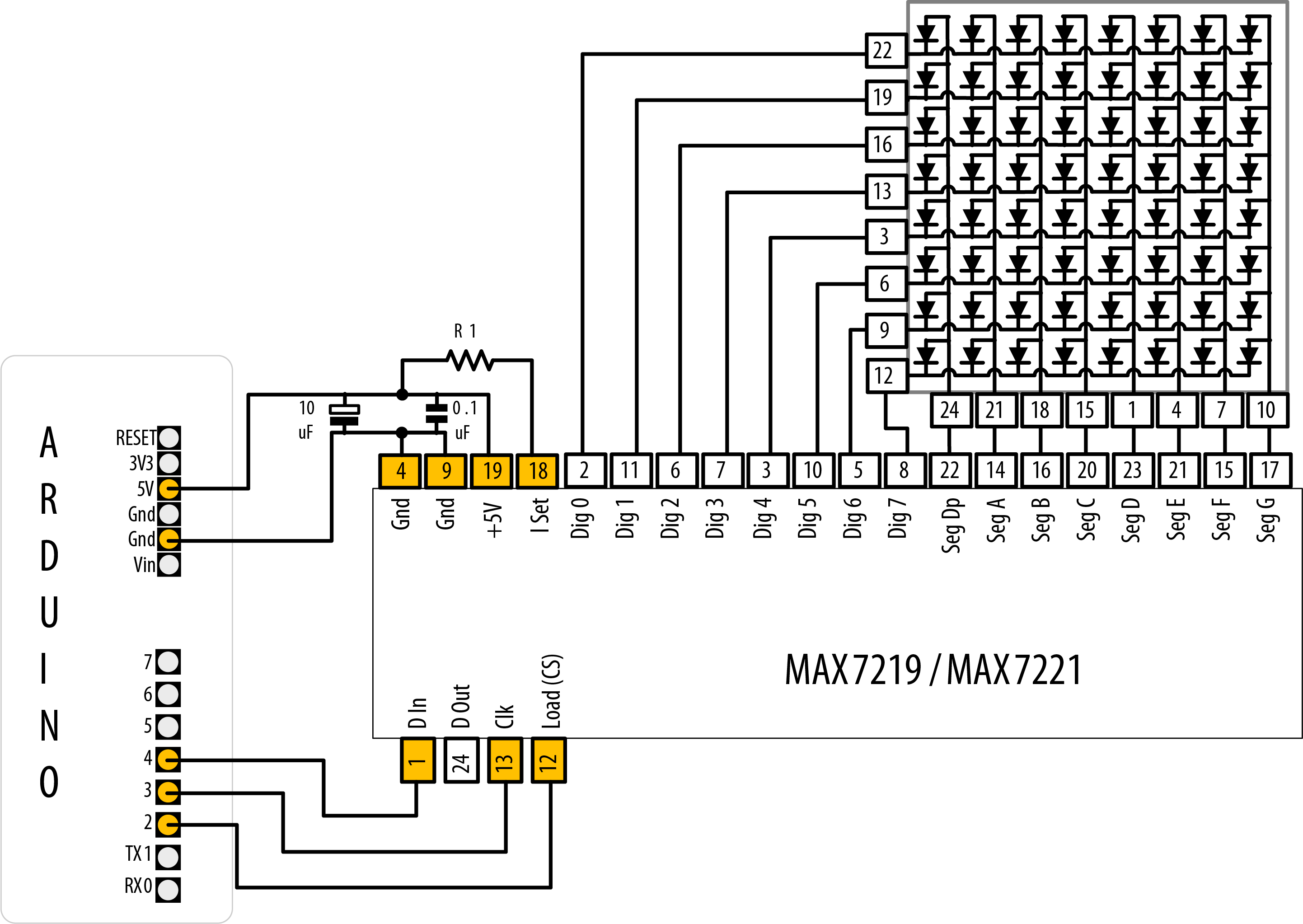
MAX72xx driving an 8×8 LED array
This sketch is based on the powerful MD_MAX72XX library, which can display text, draw objects on the display, and perform various transformations on the display. You can find the library in the Arduino Library Manager (see Recipe 16.2).
/*
   7219 Matrix demo
*/

#include <MD_MAX72xx.h>

// Pins to control 7219
#define LOAD_PIN 2
#define CLK_PIN  3
#define DATA_PIN 4

// Configure the hardware
#define MAX_DEVICES  1
#define HARDWARE_TYPE MD_MAX72XX::PAROLA_HW
MD_MAX72XX mx = MD_MAX72XX(HARDWARE_TYPE, DATA_PIN, CLK_PIN, LOAD_PIN, MAX_DEVICES);

void setup()
{
  mx.begin();
}

void loop()
{
  mx.clear(); // Clear the display

  // Draw rows and columns
  for (int r = 0; r < 8; r++)
  {
    for (int c = 0; c < 8; c++) {
      mx.setPoint(r, c, true); // Light each LED
      delay(50);
    }

    // Cycle through available brightness levels
    for (int k = 0; k <= MAX_INTENSITY; k++) {
      mx.control(MD_MAX72XX::INTENSITY, k);
      delay(100);
    }
  }
}
Discussion
A matrix is created by passing the hardware type, pin numbers for the data, load, and clock pins, and also the maximum number of devices (in case you are chaining modules). loop clears the display, then uses the setPoint method to turn pixels on. After the sketch draws a row, it cycles through the available brightness intensities and moves on to the next row.
The pin numbers shown here are for the green LEDs in the dual-color 8×8 matrix, available from Adafruit (part number 458). If you are using a different LED matrix, consult the datasheet to determine which pins correspond to each row and column. This sketch will work with a single color matrix as well, since it only uses one of the two colors. If you find that your matrix is displaying text backwards or not in the orientation you expect, you can try changing the hardware type in the line #define HARDWARE_TYPE MD_MAX72XX::PAROLA_HW from PAROLA_HW to one of GENERIC_HW, ICSTATION_HW, or FC16_HW. There is a test sketch included in the MD_MAX72xx library’s examples, MD_MAX72xx_HW_Mapper, which will run a test and help you decide the right hardware type to use.
The resistor (marked R1 in Figure 7-16) is used to control the maximum current that will be used to drive an LED. The MAX72xx datasheet has a table that shows a range of values (see Table 7-3).
| LED forward voltage | |||||
|---|---|---|---|---|---|
| Current | 1.5V | 2.0V | 2.5V | 3.0V | 3.5V |
|
40 mA |
12 kΩ |
12 kΩ |
11 kΩ |
10 kΩ |
10 kΩ |
|
30 mA |
18 kΩ |
17 kΩ |
16 kΩ |
15 kΩ |
14 kΩ |
|
20 mA |
30 kΩ |
28 kΩ |
26 kΩ |
24 kΩ |
22 kΩ |
|
10 mA |
68 kΩ |
64 kΩ |
60 kΩ |
56 kΩ |
51 kΩ |
The green LED in the LED matrix shown in Figure 7-16 has a forward voltage of 2.0 volts and a forward current of 20 mA. Table 7-3 indicates 28K ohms, but to add a little safety margin, a resistor of 30K or 33K would be a suitable choice. The capacitors (0.1 uf and 10 uf) are required to prevent noise spikes from being generated when the LEDs are switched on and off—see Recipe in Appendix C if you are not familiar with connecting decoupling capacitors.
See Also
MAX72xx data sheet: http://pdfserv.maxim-ic.com/en/ds/MAX7219-MAX7221.pdf
7.15 Increasing the Number of Analog Outputs Using PWM Extender Chips
Problem
You want to have individual control of the intensity of more LEDs than Arduino can support.
Solution
The PCA9685 chip drives up to 16 LEDs using only the two I2C data pins. Adafruit makes a breakout board that can drive multiple servos or LEDs (Adafruit part number 815). Figure 7-17 shows the connections. This sketch is based on Adafruit’s Adafruit_PWMServoDriver library, which you can install using the Arduino Library Manager (see Recipe 16.2):
/*
   PCA9685 sketch
   Create a Knight Rider-like effect on LEDs plugged into all the PCA9685 outputs
   this version assumes one PCA9685 with 16 LEDs
*/

#include <Wire.h>
#include <Adafruit_PWMServoDriver.h>

Adafruit_PWMServoDriver pwm = Adafruit_PWMServoDriver(); // assumes default I2C address of 0x40

void setup()
{
  pwm.begin(); // Initialize the PWM board
}

int channel = 0;
int channel_direction = 1;
int intensity = 4095;       // Maximum brightness
int dim = intensity / 4;    // Intensity for a dim LED

void loop()
{
  channel += channel_direction; // increment (or decrement) the channel number

  // Turn off all the pins
  for (int pin = 0; pin < 16; pin++) {
    pwm.setPin(pin, 0);
  }

  // If we've hit channel 0, set direction to 1
  if (channel == 0) {
    channel_direction = 1;
  }
  else { // If we're at channel 1 or higher, set its previous neighbor to dim
    pwm.setPin(channel - 1, dim);
  }

  // Set this channel to maximum brightness
  pwm.setPin(channel, intensity);

  if (channel < 16) { // If we're below channel 16, set the next channel to dim
    pwm.setPin(channel + 1, dim);
  }
  else { // If we've hit channel 16, set direction to -1
    channel_direction = -1;
  }

  delay(75);
}
Discussion
This sketch loops through each channel (LED), setting the previous LED to dim, the current channel to full intensity, and the next channel to dim. The LEDs are controlled through a few core methods.
The Adafruit_PWMServoDriver.begin method initializes the driver prior to any other function. The pwm.setPin method sets the duty cycle of a given channel given as a number of ticks from 0 to 4095. The first argument is the channel number followed by the brightness. Each pulse-width modulation cycle is divided into 4096 ticks. The value you supply for the brightness indicates the number of ticks in which the LED should be on. You can change the PWM frequency with the pwm.setPWMFreq method (supply the value in Hertz, from 40 to 1600).
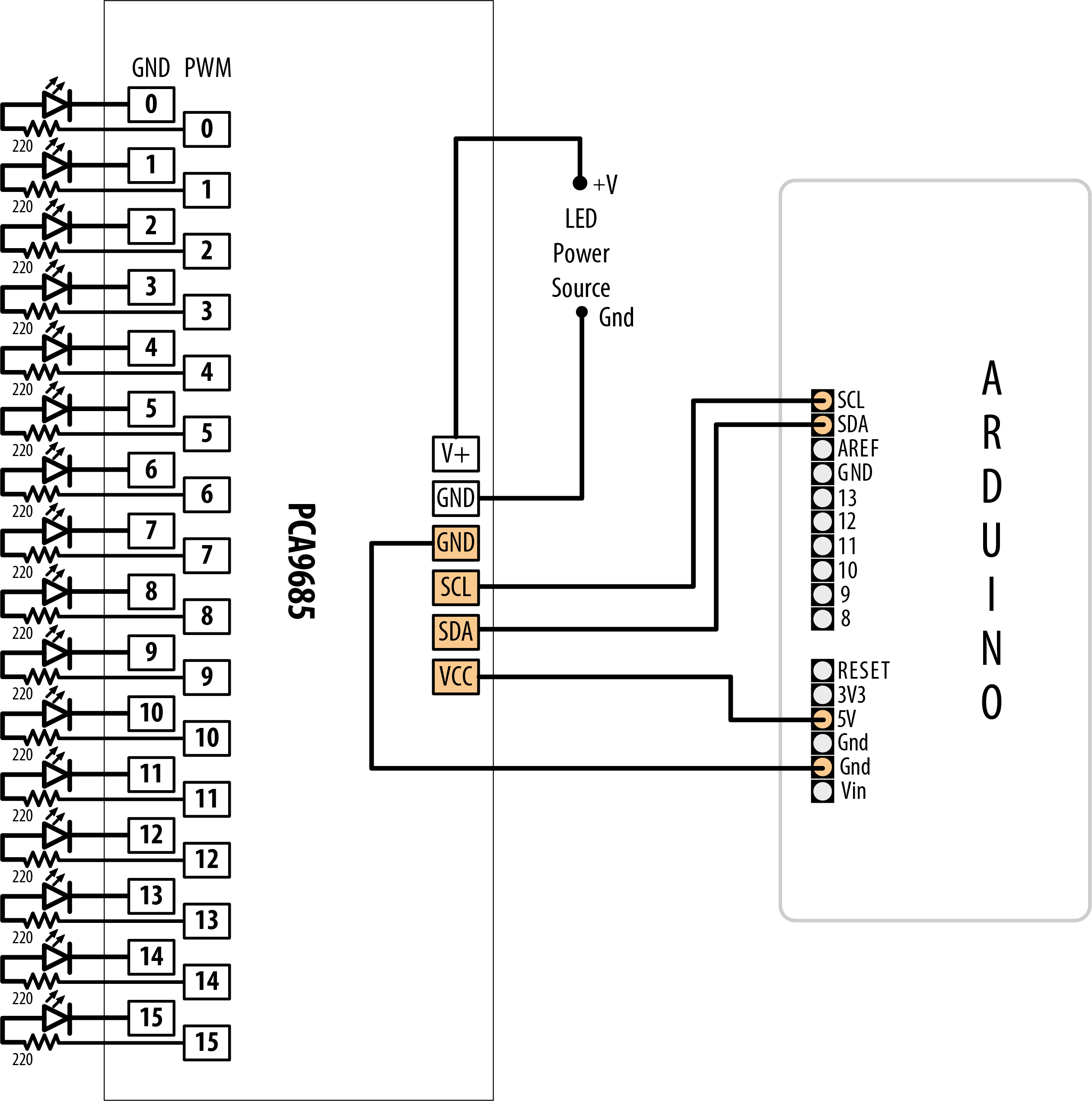
Sixteen LEDs driven using external PWM
The following functions only take effect after calling the update() method:
More functions are available in the library; see the library reference at http://adafruit.github.io/Adafruit-PWM-Servo-Driver-Library/html/class_adafruit___p_w_m_servo_driver.html.
You can chain multiple driver boards by chaining their pins together. Each board must have a unique address, which you set by soldering the pads labeled A0 throug A5. You can chain up to 62 driver boards. See https://learn.adafruit.com/16-channel-pwm-servo-driver/chaining-drivers for mre details.
7.16 Using an Analog Panel Meter as a Display
Problem
You would like to control the pointer of an analog panel meter from your sketch. Fluctuating readings are easier to interpret on an analog meter, and analog meters add a cool retro look to a project.
Solution
Connect the meter through a series resistor (5K ohms for the typical 1 mA meter) and connect to an analog (PWM) output (see Figure 7-18).

Driving an analog meter
The pointer movement corresponds to the position of a pot (variable resistor):
/*
 * AnalogMeter sketch
 * Drives an analog meter through an Arduino PWM pin
 * The meter level is controlled by a variable resistor on an analog input pin
 */

const int analogInPin = A0;   // Analog input pin connected to the variable resistor
const int analogMeterPin = 9; // Analog output pin connecting to the meter

int sensorValue = 0;        // value read from the pot
int outputValue = 0;        // value output to the PWM (analog out)

void setup()
{
  // nothing in setup
}

void loop()
{
  sensorValue = analogRead(analogInPin);            // read the analog in value
  outputValue = map(sensorValue, 0, 1023, 0, 255);  // scale for analog out
  analogWrite(analogMeterPin, outputValue);         // write the analog out value
}
Discussion
In this variation on Recipe 7.2, the Arduino analogWrite output drives a panel meter. Panel meters are usually much more sensitive than LEDs; a resistor must be connected between the Arduino output and the meter to drop the current to the level for the meter.
The value of the series resistor depends on the sensitivity of the meter; 5K ohms give full-scale deflection with a 1 mA meter. You can use 4.7K resistors, as they are easier to obtain than 5K, although you will probably need to reduce the maximum value given to analogWrite to 240 or so. Here is how you can change the range in the map function if you use a 4.7K ohm resistor with a 1 mA meter:
outputValue = map(sensorValue, 0, 1023, 0, 240); // map to meter's range
If your meter has a different sensitivity than 1 mA, you will need to use a different value series resistor. The resistor value in ohms is
- resistor = 5,000 / mA
So, a 500 microamp meter (0.5 mA) is 5,000 / 0.5, which is 10,000 (10 K) ohms. A 10 mA meter requires 500 ohms, 20 mA 250 ohms.
Some surplus meters already have an internal series resistor—you may need to experiment to determine the correct value of the resistor, but be careful not to apply too much voltage to your meter.