
Using Displays
11.0 Introduction
Liquid crystal displays (LCDs) and LED displays offer a convenient and inexpensive way to provide a user interface for a project. This chapter explains how to connect and use common text and graphical LCD/LED panels with Arduino. By far the most popular LCD is the text panel based on the Hitachi HD44780 chip. This displays two or four lines of text, with 16 or 20 characters per line (32- and 40-character versions are available, but usually at higher prices). A library for driving text LCD displays is provided with Arduino, and you can print text on your LCD as easily as on the Serial Monitor (see Chapter 4), because LCD and serial share the same underlying print functions.
LCDs can do more than display simple text: words can be scrolled or highlighted and you can display a selection of special symbols and non-English characters.
You can create your own symbols and block graphics with a text LCD, but if you want fine graphical detail, you need a graphical display. Graphical LCD (GLCD) and graphical LED displays are available at a small price premium over text displays.
Graphical displays can have more wires connecting to Arduino than most other recipes in this book. Incorrect connections are the major cause of problems with graphical displays, so take your time wiring things up and triple-check that things are connected correctly. An inexpensive multimeter capable of measuring voltage and resistance is a big help for verifying that your wiring is correct. It can save you a lot of head scratching if nothing is being displayed. You don’t need anything fancy, as even the cheapest multimeter will help you verify that the correct pins are connected and that the voltages are correct.
11.1 Connecting and Using a Text LCD Display
Problem
You have a text LCD based on the industry-standard HD44780 or a compatible controller chip, and you want to display text and numeric values.
Solution
The Arduino software includes the LiquidCrystal library for driving LCD displays based on the HD44780 chip such as the SparkFun LCD-00255 or Adafruit part number 181.
Note
Most text LCDs supplied for use with Arduino will be compatible with the Hitachi HD44780 controller. If you are not sure about your controller, check the datasheet to see if it is a 44780 or compatible. If your LCD has a backpack-style controller board on it, you may be able to interface with it over a serial protocol with far fewer wires. See #sending_data_to_two_serial_devices_a for more details.
To get the display working, you need to wire the power, data, and control pins. Connect the data and status lines to digital output pins, and wire up a contrast potentiometer and connect the power lines. If your display has a backlight, this needs connecting, usually through a resistor.
Figure 11-1 shows the most common LCD connections. It’s important to check the datasheet for your LCD to verify the pin connections. Table 11-1 shows the most common pin connections, but if your LCD uses different pins, make sure it is compatible with the Hitachi HD44780—this recipe will only work on LCD displays that are compatible with that chip. The LCD will have 16 pins (or 14 pins if there is no backlight)—make sure you identify pin 1 on your panel; it may be in a different position than shown in the figure.
Note
Most problems with LCDs are due to bad connections. Double check that the Arduino wires go to the correct LCD pins, as these could be positioned or numbered differently from what is shown in Figure 11-1. Also check that the wires or headers are properly soldered.

Connections for a text LCD
Note
You may wonder why LCD pins 7 through 10 are not connected. The LCD display can be connected using either four pins or eight pins for data transfer. This recipe uses the four-pin mode because this frees up the other four Arduino pins for other uses. There is a theoretical performance improvement using eight pins, but it’s insignificant and not worth the loss of four Arduino pins.
| LCD pin | Function | Arduino pin |
|---|---|---|
|
1 |
Gnd or 0V or Vss |
Gnd |
|
2 |
+5V or Vdd |
5V |
|
3 |
Vo or contrast |
|
|
4 |
RS |
12 |
|
5 |
R/W |
Gnd |
|
6 |
E |
11 |
|
7 |
D0 |
|
|
8 |
D1 |
|
|
9 |
D2 |
|
|
10 |
D3 |
|
|
11 |
D4 |
5 |
|
12 |
D5 |
4 |
|
13 |
D6 |
3 |
|
14 |
D7 |
2 |
|
15 |
A or anode |
|
|
16 |
K or cathode |
You will need to connect a 10K potentiometer to provide the contrast voltage to LCD pin 3. Without the correct voltage on this pin, you may not see anything displayed. In Figure 11-1, one side of the pot connects to Gnd (ground), the other side connects to Arduino +5V, and the center of the pot goes to LCD pin 3. The LCD is powered by connecting Gnd and +5V from Arduino to LCD pins 1 and 2.
Many LCD panels have an internal lamp called a backlight to illuminate the display. Your datasheet should indicate whether there is a backlight and if it requires an external resistor—many do need this to prevent burning out the backlight LED assembly (if you are not sure, you can be safe by using a 220 ohm resistor). The backlight is polarized, so make sure pin 15 is connected to +5V and pin 16 to Gnd. (The resistor is shown connected between pin 16 and Gnd, but it can also be connected between pin 15 and +5V.)
Double-check the wiring before you apply power, as you can damage the LCD if you connect the power pins incorrectly. To run the HelloWorld sketch provided with Arduino, click the IDE Files menu item and navigate to Examples→Library→LiquidCrystal→HelloWorld.
The following code is modified slightly from the example. Change numRows and numCols to match the rows and columns in your LCD:
/*
 * LiquidCrystal Library - Hello World
 *
 * Demonstrates the use of a 16 × 2 LCD display.
 * https://www.arduino.cc/en/Tutorial/HelloWorld
 */

#include <LiquidCrystal.h> // include the library code

//constants for the number of rows and columns in the LCD
const int numRows = 2;
const int numCols = 16;

// initialize the library with the numbers of the interface pins
LiquidCrystal lcd(12, 11, 5, 4, 3, 2);

void setup()
{
  lcd.begin(numCols, numRows);
  lcd.print("Hello, World!");  // Print a message to the LCD.
}

void loop()
{
  // set the cursor to column 0, line 1
  // (row numbering starts with 0, so line 1 is the second row):
  lcd.setCursor(0, 1);
  // print the number of seconds since the sketch started:
  lcd.print(millis()/1000);
}
Run the sketch; you should see “hello world” displayed on the first line of your LCD. The second line will display a number that increases by one every second.
Discussion
If you don’t see any text and you have double-checked that all wires are connected correctly, you may need to adjust the contrast pot. With the pot shaft rotated to one side (usually the side connected to Gnd), you will have maximum contrast and should see blocks appear in all the character positions. With the pot rotated to the other extreme, you probably won’t see anything at all. The correct setting will depend on many factors, including viewing angle and temperature—turn the pot until you get the best-looking display.
If you can’t see blocks of pixels appear at any setting of the pot, check that the LCD is being driven on the correct pins.
Once you can see text on the screen, using the LCD in a sketch is easy. You use similar print commands to those for serial printing, covered in Chapter 4. The next recipe reviews the print commands and explains how to control text position.
See Also
See the LiquidCrystal reference: http://arduino.cc/en/Reference/LiquidCrystalPrint.
See Chapter 4 for details on print commands.
The datasheet for the Hitachi HD44780 LCD controller is the definitive reference for detailed, low-level functionality. The Arduino library insulates you from most of the complexity, but if you want to read about the raw capabilities of the chip, you can download the datasheet from https://www.sparkfun.com/datasheets/LCD/HD44780.pdf.
The LCD page in the Arduino Playground contains software and hardware tips and links: http://playground.arduino.cc/Code/LCD .
11.2 Formatting Text
Problem
You want to control the position of text displayed on the LCD screen; for example, to display values in specific positions.
Solution
This sketch displays a countdown from 9 to 0. It then displays a sequence of digits in three columns of four characters. Change numRows and numCols to match the rows and columns in your LCD:
/*
 * LiquidCrystal Library - FormatText
 */

#include <LiquidCrystal.h> // include the library code:

//constants for the number of rows and columns in the LCD
const int numRows = 2;
const int numCols = 16;

int count;

// initialize the library with the numbers of the interface pins
LiquidCrystal lcd(12, 11, 5, 4, 3, 2);

void setup()
{
  lcd.begin(numCols, numRows);
  lcd.print("Starting in ");  // this string is 12 characters long
  for(int i=9; i > 0; i--)    // count down from 9
  {
    // the top line is row 0
    lcd.setCursor(12,0); // move the cursor to the end of the string
    lcd.print(i);
    delay(1000);
  }
}

void loop()
{
  int columnWidth = 4;         //spacing for the columns
  int displayColumns = 3;      //how many columns of numbers

  lcd.clear();
  for( int col=0; col < displayColumns; col++)
  {
    lcd.setCursor(col * columnWidth, 0);
    count = count+ 1;
    lcd.print(count);
  }
  delay(1000);
}
Discussion
The lcd.print functions are similar to Serial.print. In addition, the LCD library has commands that control the cursor location (the row and column where text will be printed).
The lcd.print statement displays each new character after the previous one. Text printed beyond the end of a line may not be displayed or may be displayed on another line. The lcd.setCursor() command enables you to specify where the next lcd.print will start. You specify the column and row position (the top-left corner is 0,0). Once the cursor is positioned, the next lcd.print will start from that point, and it will overwrite existing text. The sketch in this recipe’s Solution uses this to print numbers in fixed locations.
For example, in setup:
lcd.setCursor(12,0); // move the cursor to the 13th position
lcd.print(i);
lcd.setCursor(12,0) ensures that each number is printed in the same position, the thirteenth column, first row, producing the digit shown at a fixed position, rather than each number being displayed after the previous number.
Note
Rows and columns start from zero, so setCursor(4,0) would set the cursor to the fifth column on the first row.
The following lines use setCursor to space out the start of each column to provide columnwidth spaces from the start of the previous column:
lcd.setCursor(col * columnWidth, 0);
count = count+ 1;
lcd.print(count);
lcd.clear clears the screen and moves the cursor back to the top-left corner:
lcd.clear();
Here is a variation on loop that displays numbers using all the rows of your LCD. Replace your loop code with the following (make sure you set numRows and numCols at the top of the sketch to match the rows and columns in your LCD):
void loop()
{
int columnWidth = 4;
int displayColumns = 3;

  lcd.clear();
  for(int row=0; row < numRows; row++)
  {
    for( int col=0; col < displayColumns; col++)
    {
      lcd.setCursor(col * columnWidth, row);
      count = count+ 1;
      lcd.print(count);
    }
  }
  delay(1000);
}
The first for loop steps through the available rows, and the second for loop steps through the columns.
To adjust how many numbers are displayed in a row to fit the LCD, calculate the displayColumns value rather than setting it. Change:
int displayColumns = 3;
to:
int displayColumns = numCols / columnWidth;
See Also
The LiquidCrystal library tutorial: https://www.arduino.cc/en/Reference/LiquidCrystal
11.3 Turning the Cursor and Display On or Off
Problem
You want to blink the cursor and turn the display on or off. You may also want to draw attention to a specific area of the display.
Solution
This sketch shows how you can cause the cursor (a flashing block at the position where the next character will be displayed) to blink. It also illustrates how to turn the display on and off; for example, to draw attention by blinking the entire display:
/*
 * blink
 */

// include the library code:
#include <LiquidCrystal.h>

// initialize the library with the numbers of the interface pins
LiquidCrystal lcd(12, 11, 5, 4, 3, 2);

void setup()
{
  // set up the LCD's number of columns and rows and:
  lcd.begin(16, 2);
  // Print a message to the LCD.
  lcd.print("hello, world!");
}

void loop()
{
  lcd.setCursor(0, 1);

  lcd.print("cursor blink");
  lcd.blink();
  delay(2000);

  lcd.noBlink();
  lcd.print(" noBlink");
  delay(2000);

  lcd.clear();

  lcd.print("Display off ...");
  delay(1000);
  lcd.noDisplay();
  delay(2000);

  lcd.display();  // turn the display back on

  lcd.setCursor(0, 0);
  lcd.print(" display flash !");
  displayBlink(2, 250);  // blink twice
  displayBlink(2, 500);  // and again for twice as long

  lcd.clear();
}

void displayBlink(int blinks, int duration)
{
  while(blinks--)
  {
    lcd.noDisplay();
    delay(duration);
    lcd.display();
    delay(duration);
  }
}
Discussion
The sketch calls blink and noBlink functions to toggle cursor blinking on and off.
The code to blink the entire display is in a function named displayBlink that makes the display flash a specified number of times. The function uses lcd.display() and lcd.noDisplay() to turn the display text on and off (without clearing it from the screen’s internal memory).
11.4 Scrolling Text
Problem
You want to scroll text; for example, to create a marquee that displays more characters than can fit on one line of the LCD display.
Solution
This sketch demonstrates both lcd.ScrollDisplayLeft and lcd.ScrollDisplayRight.
It scrolls a line of text to the left when tilted and to the right when not tilted. Connect one side of a tilt sensor to pin 7 and the other pin to Gnd (see Recipe 6.2 if you are not familiar with tilt sensors):
/*
 * Scroll
 * this sketch scrolls text left when tilted
 * text scrolls right when not tilted.
 */

#include <LiquidCrystal.h>

// initialize the library with the numbers of the interface pins
LiquidCrystal lcd(12, 11, 5, 4, 3, 2);
const int numRows = 2;
const int numCols = 16;

const int tiltPin = 7; // pin connected to tilt sensor

const char textString[] = "tilt to scroll";
const int textLen = sizeof(textString) - 1; // the number of characters
bool isTilted = false;

void setup()
{
  // set up the LCD's number of columns and rows:
  lcd.begin(numCols, numRows);
  pinMode(tiltPin, INPUT_PULLUP);
  lcd.print(textString);
}

void loop()
{
  if(digitalRead(tiltPin) == LOW && isTilted == false)
  {
    // here if tilted left so scroll text left
    isTilted = true;
    for (int position = 0; position  < textLen; position++)
    {
      lcd.scrollDisplayLeft();
      delay(150);
    }
  }
  if(digitalRead(tiltPin) == HIGH && isTilted == true)
  {
    // here if previously tilted but now flat, so scroll text right
    isTilted = false;
    for (int position = 0; position  < textLen; position++)
    {
      lcd.scrollDisplayRight();
      delay(150);
    }
  }
}
Discussion
The first half of the loop code handles the change from not tilted to tilted. The code checks to see if the tilt switch is closed (LOW) or open (HIGH). If it’s LOW and the current state (stored in the isTilted variable) is not tilted, the text is scrolled left. The delay in the for loop controls the speed of the scroll; adjust the delay if the text moves too fast or too slow.
The second half of the code uses similar logic to handle the change from tilted to not tilted.
A scrolling capability is particularly useful when you need to display more text than can fit on an LCD line.
This sketch has a marquee function that will scroll text up to 32 characters in length:
/*
 * Marquee
 * this sketch can scroll a very long line of text
 */

#include <LiquidCrystal.h>

LiquidCrystal lcd(12, 11, 5, 4, 3, 2);
const int numRows = 2;
const int numCols = 16;

void setup()
{
  // set up the LCD's number of columns and rows:
  lcd.begin(numCols, numRows);
  marquee("This is a very long string of text that will scroll");
}

void loop()
{
}

// this function uses scrolling to display a message up to 32 bytes long
void marquee(char *text)
{
  lcd.print(text);
  delay(1000);
  for (int position = 0; position < strlen(text)-numCols; position++)
  {
    lcd.scrollDisplayLeft();
    delay(300);
  }
}
The sketch uses the lcd.scrollDisplayLeft function to scroll the display when the text is longer than the width of the screen.
The LCD chip has internal memory that stores the text. This memory is limited (32 bytes on most four-line displays). If you try to use longer messages, they may start to wrap over themselves. If you want to scroll longer messages (e.g., a tweet), or control scrolling more precisely, you need a different technique. The following function stores the text in RAM on Arduino and sends sections to the screen to create the scrolling effect. These messages can be any length that can fit into Arduino memory:
// this version of marquee uses manual scrolling for very long messages
void marquee(char *text)
{
  int length = strlen(text); // the number of characters in the text
  if(length < numCols)
    lcd.print(text);
  else
  {
    int pos;
    for(pos = 0; pos < numCols; pos++)
       lcd.print(text[pos]);
    delay(1000); // allow time to read the first line before scrolling
    pos=1;
    while(pos <= length - numCols)
    {
      lcd.setCursor(0,0);
      for(int i=0; i < numCols; i++)
        lcd.print(text[pos+i]);
      delay(300);
      pos = pos + 1;
    }
  }
}
11.5 Displaying Special Symbols
Problem
You want to display special symbols: ° (degrees), ¢, ÷, π (pi), or any other symbol stored in the LCD character memory.
Solution
Identify the character code you want to display by locating the symbol in the character pattern table in the LCD datasheet. This sketch prints some common symbols in setup. It then shows all displayable symbols in loop:
/*
 * LiquidCrystal Library - Special Chars
 */

#include <LiquidCrystal.h>

//set constants for number of rows and columns to match your LCD
const int numRows = 2;
const int numCols = 16;

// defines for some useful symbols
const byte degreeSymbol = B11011111;
const byte piSymbol     = B11110111;
const byte centsSymbol  = B11101100;
const byte sqrtSymbol   = B11101000;
const byte omegaSymbol  = B11110100;  // the symbol used for ohms

byte charCode = 32; // the first printable ascii character
int col;
int row;

// initialize the library with the numbers of the interface pins
LiquidCrystal lcd(12, 11, 5, 4, 3, 2);

void setup()
{
  lcd.begin(numRows, numCols);

  showSymbol(degreeSymbol, "degrees");
  showSymbol(piSymbol,     "pi");
  showSymbol(centsSymbol,  "cents");
  showSymbol(sqrtSymbol,   "sqrt");
  showSymbol(omegaSymbol,  "ohms");
  lcd.clear();

}

void loop()
{
  lcd.write(charCode);
  calculatePosition();
  if(charCode == 255)
  {
    // finished all characters so wait another few seconds and start over
    delay(2000);
    lcd.clear();
    row = col = 0;
    charCode = 32;
  }
  charCode = charCode + 1;
}

void calculatePosition()
{
  col = col + 1;
  if( col == numCols)
  {
    col = 0;
    row = row + 1;
    if( row == numRows)
    {
      row = 0;
      delay(2000); // pause
      lcd.clear();
    }
    lcd.setCursor(col, row);
  }
}

// function to display a symbol and its description
void showSymbol(byte symbol, char *description)
{
  lcd.clear();
  lcd.write(symbol);
  lcd.print(' '); // add a space before the description
  lcd.print(description);
  delay(3000);
}
Discussion
A table showing the available character patterns is in the datasheet for the LCD controller chip (you can find it on page 17 of the datasheet at https://www.sparkfun.com/datasheets/LCD/HD44780.pdf).
To use the table, locate the symbol you want to display. The code for that character is determined by combining the binary values for the column and row for the desired symbol (see Figure 11-2).

Using datasheet to derive character codes
For example, the degree symbol (°) is the third-from-last entry at the bottom row of the table shown in Figure 11-2. Its column indicates the upper four bits are 1101 and its row indicates the lower four bits are 1111. Combining these gives the code for this symbol: B11011111. You can use this binary value or convert this to its hex value (0xDF) or decimal value (223). Note that Figure 11-2 shows only 4 of the 16 actual rows in the datasheet.
The LCD screen can also show any of the ASCII characters listed in the datasheet by passing the ASCII value to lcd.write.
The sketch uses a function named showSymbol to print the symbol and its description:
void showSymbol(byte symbol, char *description)
(See Recipe 2.6 if you need a refresher on using character strings and passing them to functions.)
See Also
Datasheet for Hitachi HD44780 display: https://www.sparkfun.com/datasheets/LCD/HD44780.pdf
11.6 Creating Custom Characters
Problem
You want to define and display characters or symbols (glyphs) that you have created. The symbols you want are not predefined in the LCD character memory.
Solution
Uploading the following code will create an animation of a face, switching between smiling and frowning:
/*
 * custom_char sketch
 * creates an animated face using custom characters
 */

#include <LiquidCrystal.h>
LiquidCrystal lcd(12, 11, 5, 4, 3, 2);

byte happy[8] =
{
  B00000,
  B10001,
  B00000,
  B00000,
  B10001,
  B01110,
  B00000,
  B00000
};

byte saddy[8] =
{
  B00000,
  B10001,
  B00000,
  B00000,
  B01110,
  B10001,
  B00000,
  B00000
};

void setup() {
  lcd.createChar(0, happy);
  lcd.createChar(1, saddy);
  lcd.begin(16, 2);
}

void loop() {
  for (int i=0; i<2; i++)
  {
    lcd.setCursor(0,0);
    lcd.write(i);
    delay(500);
  }
}
Discussion
The LiquidCrystal library enables you to create up to eight custom characters, which can be printed as character codes 0 through 8. Each character on the screen is drawn on a grid of 5×8 pixels. To define a character, you need to create an array of eight bytes. Each byte defines one of the rows in the character. When written as a binary number, the 1 indicates a pixel is on, 0 is off (any values after the fifth bit are ignored). The sketch example creates two characters, named happy and saddy (see Figure 11-3).

Defining custom characters
The following line in setup creates the character using data defined in the happy array that is assigned to character 0:
lcd.createChar(0, happy);
To print the custom character to the screen you would use this line:
lcd.write(0);
Note
Note the difference between writing a character with or without an apostrophe. The following will print a zero, not the happy symbol:
lcd.write('0'); // this prints a zero
Code in the for loop switches between character 0 and character 1 to produce an animation.
11.7 Displaying Symbols Larger Than a Single Character
Problem
You want to combine two or more custom characters to print symbols larger than a single character; for example, double-height numbers on the screen.
Solution
The following sketch writes double-height numbers using custom characters:
/*
 * customChars
 * This sketch displays double-height digits
 * the bigDigit arrays were inspired by Arduino forum member dcb
 */

#include <LiquidCrystal.h>

LiquidCrystal lcd(12, 11, 5, 4, 3, 2);

byte glyphs[5][8] = {
  { B11111,B11111,B00000,B00000,B00000,B00000,B00000,B00000 },
  { B00000,B00000,B00000,B00000,B00000,B00000,B11111,B11111 },
  { B11111,B11111,B00000,B00000,B00000,B00000,B11111,B11111 },
  { B11111,B11111,B11111,B11111,B11111,B11111,B11111,B11111 } ,
  { B00000,B00000,B00000,B00000,B00000,B01110,B01110,B01110 } };

const int digitWidth = 3; // the width in characters of a big digit
                          // (excludes space between characters)

//arrays  to index into custom characters that will comprise the big numbers
// digits 0 - 4                             0      1       2      3      4
const char bigDigitsTop[10][digitWidth]={ 3,0,3, 0,3,32, 2,2,3, 0,2,3, 3,1,3,
// digits 5-9                               5      6      7        8      9
                                          3,2,2, 3,2,2, 0,0,3,   3,2,3, 3,2,3};

const char bigDigitsBot[10][ digitWidth]={ 3,1,3, 1,3,1,  3,1,1, 1,1,3, 32,32,3,
                                           1,1,3, 3,1,3, 32,32,3, 3,1,3, 1,1,3};

char buffer[12]; // used to convert a number into a string
void setup ()
{
  lcd.begin(20,4);
  // create the custom glyphs
  for(int i=0; i < 5; i++)
    lcd.createChar(i, glyphs[i]); // create the 5 custom glyphs
  // show a countdown timer
  for(int digit = 9; digit >= 0; digit--)
  {
    showDigit(digit, 0);  // show the digit
    delay(1000);
  }
  lcd.clear();
}

void loop ()
{
  // now show the number of seconds since the sketch started
  int number = millis() / 1000;
  showNumber(number, 0);
  delay(1000);
  Serial.begin(9600);
}

void showDigit(int digit, int position)
{
  lcd.setCursor(position * (digitWidth + 1), 0);
  for(int i=0; i < digitWidth; i++)
    lcd.write(bigDigitsTop[digit][i]);
  lcd.setCursor(position * (digitWidth + 1), 1);
  for(int i=0; i < digitWidth; i++)
    lcd.write(bigDigitsBot[digit][i]);
}

void showNumber(int value, int position)
{
  int index; // index to the digit being printed, 0 is the leftmost digit
  String valStr = String(value);

  // display each digit in sequence
  for(index = 0; index < 5; index++) // display up to five digits
  {
    char c = valStr.charAt(index);
    if(c == 0)  // check for null (not the same as '0')
      return; // the end of string character is a null
    c = c - 48; // convert ascii value to a numeric value (see Chapter 2)
    showDigit(c, position + index);
  }
}
Discussion
The LCD display has fixed-size characters, but you can create larger symbols by combining characters. This recipe creates five custom characters using the technique described in Recipe 11.6. These symbols (see Figure 11-4) can be combined to create double-sized digits (see Figure 11-5). The sketch displays a countdown from 9 to 0 on the LCD using the big digits. It then displays the number of seconds since the sketch started.
The glyphs array defines pixels for the five custom characters. The array has two dimensions given in the square brackets:
byte glyphs[5][8] = {
[5] is the number of glyphs and [8] is the number of rows in each glyph. Each element contains 1s and 0s to indicate whether a pixel is on or off in that row. If you compare the values in glyph[0] (the first glyph) with Figure 11-2, you can see that the 1s correspond to dark pixels:
{ B11111,B11111,B00000,B00000,B00000,B00000,B00000,B00000 } ,

Custom characters used to form big digits

Ten big digits composed of custom glyphs
Each big number is built from six of these glyphs, three forming the upper half of the big digit and three forming the lower half. bigDigitsTop and bigDigitsBot are arrays defining which custom glyph is used for the top and bottom rows on the LCD screen.
See Also
See Chapter 7 for information on 7-segment LED displays if you need really big numerals. Note that 7-segment displays can give you digit sizes from one-half inch to two inches or more. They can use much more power than LCD displays and don’t present letters and symbols very well, but they are a good choice if you need something big.
11.8 Displaying Pixels Smaller Than a Single Character
Problem
You want to display information with finer resolution than an individual character; for example, to display a bar chart.
Solution
Recipe 11.7 describes how to build big symbols composed of more than one character. This recipe uses custom characters to do the opposite; it creates eight small symbols, each a single pixel higher than the previous one (see Figure 11-6).
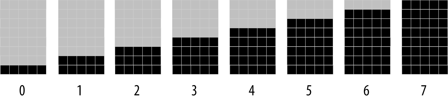
Eight custom characters used to form vertical bars
These symbols are used to draw bar charts, as shown in the sketch that follows:
/*
 * customCharPixels
 */

#include <LiquidCrystal.h>

LiquidCrystal lcd(12, 11, 5, 4, 3, 2);

//set constants for number of rows and columns to match your LCD
const int numRows = 2;
const int numCols = 16;

// array of bits defining pixels for 8 custom characters
// ones and zeros indicate if a pixel is on or off

byte glyphs[8][8]  = {
      {B00000,B00000,B00000,B00000,B00000,B00000,B00000,B11111},   // 0
      {B00000,B00000,B00000,B00000,B00000,B00000,B11111,B11111},   // 1
      {B00000,B00000,B00000,B00000,B00000,B11111,B11111,B11111},   // 2
      {B00000,B00000,B00000,B00000,B11111,B11111,B11111,B11111},   // 3
      {B00000,B00000,B00000,B11111,B11111,B11111,B11111,B11111},   // 4
      {B00000,B00000,B11111,B11111,B11111,B11111,B11111,B11111},   // 5
      {B00000,B11111,B11111,B11111,B11111,B11111,B11111,B11111},   // 6
      {B11111,B11111,B11111,B11111,B11111,B11111,B11111,B11111}};  // 7

void setup ()
{
  lcd.begin(numCols, numRows);
  for(int i=0; i < 8; i++)
    lcd.createChar(i, glyphs[i]);     // create the custom glyphs
  lcd.clear();
}

void loop ()
{
  for( byte i=0; i < 8; i++)
    lcd.write(i);   // show all eight single height bars
  delay(2000);
  lcd.clear();
}
Discussion
The sketch creates eight characters, each a single pixel higher than the one before; see Figure 11-6. These are displayed in sequence on the top row of the LCD. These “bar chart” characters can be used to display values in your sketch that can be mapped to a range from 0 to 7. For example, the following will display a value read from analog input 0:
int value = analogRead(A0);
byte glyph = map(value, 0,1023, 0,8); // proportional value from 0 through 7
lcd.write(glyph);
delay(100);
You can stack the bars for greater resolution. The doubleHeightBars function shown in the following code displays a value from 0 to 15 with a resolution of 16 pixels, using two lines of the display:
void doubleHeightBars(int value, int column)
{
  char upperGlyph;
  char lowerGlyph;

  if(value < 8)
  {
    upperGlyph = ' ';  // no pixels lit
    lowerGlyph = value;
  }
  else
  {
    upperGlyph = value - 8;
    lowerGlyph = 7; // all pixels lit
  }

  lcd.setCursor(column, 0); // do the upper half
  lcd.write(upperGlyph);
  lcd.setCursor(column, 1); // now to the lower half
  lcd.write(lowerGlyph);
}
The doubleHeightBars function can be used as follows to display the value of an analog input:
for(int i=0; i < 16; i++)
{
  int value = analogRead(A0);
  value = map(value, 0, 1023, 0,16);
  doubleHeightBars(value, i); // show a value from 0 to 15
  delay(1000);  // one second interval between readings
}
If you want horizontal bars, you can define five characters, each a single pixel wider than the previous one, and use similar logic to the vertical bars to calculate the character to show.
11.9 Selecting a Graphical LCD Display
Problem
You want to show graphics or text on either a color or monochrome display.
Solution
There many graphical displays suitable for use with Arduino. Some of the things to consider when choosing a display are: resolution (number of pixels and text lines), display size, color, touch screen capability, on-board SD memory, and price. You will also need a library to interface with your display and you may be spoiled for choice for well written and documented libraries that you can use. This recipe provides an overview of what is available along with links for more reading to help you select and use the display that is right for your project.
The increasingly rapid introduction of new smartphone and related devices has resulted in reducing costs to a level where monochrome or color displays can be purchased for a fraction of the cost of an Arduino board. When selecting a graphical display, the first thing to consider is color or monochrome. This is partially an aesthetic decision, but it can also be influenced by things like: display size (in some cases, larger color panels may be cheaper than large monochrome displays), power consumption (OLED displays described later need less power), touch capability (color panels tend to have better support for touch) and connection type.
Graphical displays that are popular for Arduino projects typically use either Liquid Crystal Display (LCD) or Organic Light-Emitting Diode (OLED) technology. OLED is newer technology that consumes less power than a conventional LCD because it does not need a backlight to be visible in low light conditions. However, OLED panels cost more to manufacture so they tend to be much smaller in size than similarly priced LCD panels. Color OLEDs are available but are very expensive and those sold for use with Arduino tend to be very small.
Discussion
Monochrome displays were historically much cheaper than color but the price differential is decreasing. Monochrome displays are a good choice if you want a small display or if low current consumption is important. Also, sketch memory needed for monochrome is generally much less than color so that may be a factor if you have limited available memory.
There are Adafruit libraries for the SSD1306, SSD1325, SSD1331 and SSD1351 OLED displays. A nice feature of these is that the API is similar to the Adafruit color libraries if you want to use both mono and color panels in future projects, or may upgrade the screen in the project you are working on at a later date. The documentation for the Adafruit displays and libraries can be found here: https://learn.adafruit.com/monochrome-oled-breakouts
A highly capable monochrome library supporting over 60 controller variants is the U8g2 library. These include: SSD1305, SSD1306, SSD1309, SSD1322, SSD1325, SSD1327, SSD1606, SH1106, T6963, RA8835, LC7981, PCD8544, PCF8812, UC1604, UC1608, UC1610, UC1611, UC1701, ST7565, ST7567, NT7534, IST3020, ST7920, LD7032, KS0108
U8G2 is a good choice if you want the widest range of monochrome options. The full list of controller variants can be found on the U8g2 website: https://github.com/olikraus/u8g2/wiki/u8g2setupcpp
This library supports common connection types including I2C, SPI and parallel. If you have a monochrome graphical display, the U8g2 will more than likely work with it. You can find the library source at https://github.com/olikraus/u8g2. The U8G2 wiki has extensive documentation: https://github.com/olikraus/u8g2/wiki.
Color displays offer the ability to display information in full color. The Adafruit GFX library provides a common set of graphic primitives that support many display specific libraries such as the Adafruit_ST7735 Adafruit_HX8340B, Adafruit_HX8357D, Adafruit_ILI9340/1,Adafruit_PCD8544 libraries. This library is popular because it is well documented with many tutorials. The Adafruit tutorial covering the graphical functions common to all Adafruit libraries is at: https://learn.adafruit.com/adafruit-gfx-graphics-library. The Adafruit Arcada library combines GFX support with a large collection of functionality useful for creating games or rich graphical user experiences, including various types of user input: https://github.com/adafruit/Adafruit_Arcada.
Library for four wire resistive touch screens: https://github.com/adafruit/Touch-Screen-Library
The library for touch screens: https://github.com/adafruit/Adafruit_FT6206_Library
If you have one of the low cost TFT screens with or without touch capability that use ITDB02 or ILI9341 display controllers, have a look at the UTFT library: http://www.rinkydinkelectronics.com/library.php?id=51
URTouch is a companion to UTFT supporting touch screens: http://www.rinkydinkelectronics.com/library.php?id=92
Beware low cost displays with limited or no supplier support
Because of the vast variety of graphical displays, selecting a display can be daunting. If you don’t have the experience to understand highly technical display controller datasheets then do not be tempted by some ultra-cheap item from suppliers that do not provide documentation and support. A product listing may say it comes with software for Arduino but it is not unusual for that code to not actually work with the supplied display or with the latest Arduino environment. The safer choice is through suppliers like Adafruit and SparkFun that have libraries and tutorials and support forums for their products.
11.10 Control a Full-Color LCD Display
Problem
You want to display full-color graphics on a graphical LCD such as the ones based on the ST7735.
Solution
This recipe uses the Adafruit ST7735 and ST7789 Library, which provides support for ST7735 and ST7789-based TFT LCD displays, such as the 1.8” breakout (Adafruit product id 358) or the 2.0” IPS breakout (product id 4311). Or if you want a simple and strange all-in-one option, the Adafruit HalloWing M0 combines a SAMD21 dev board, 8MB of flash, sensors, speaker driver, and a 1.44 inch full-color LCD, all on a skull-shaped PCB board. You can install this library using the Arduino Library Manager (see Chapter 16).
The sketch initializes the display on a HalloWing M0, shows three lines of text in varying sizes, and then switches to an animation of a yellow ball moving back and forth:
/*
 * Adafruit GFX ST7735 sketch
 * Display text and a moving ball on the display
 */

#include <Adafruit_GFX.h>    // Core graphics library
#include <Adafruit_ST7735.h> // Hardware-specific library for ST7735
#include <SPI.h>

// Define the connections for your panel. This will vary depending on
// your display and the board you are using
#define TFT_CS   39
#define TFT_RST  37
#define TFT_DC   38
#define TFT_BACKLIGHT  7
Adafruit_ST7735 tft = Adafruit_ST7735(TFT_CS, TFT_DC, TFT_RST);

void setup(void)
{
  tft.initR(INITR_144GREENTAB); // Initialize ST7735, green tab packaging

  pinMode(TFT_BACKLIGHT, OUTPUT); // Backlight pin
  digitalWrite(TFT_BACKLIGHT, HIGH); // Turn on the backlight

  tft.setRotation(2); // This will depend on how you mounted the panel

  tft.fillScreen(ST77XX_BLACK); // Fill the screen with black

  // Display some text in a variety of fonts
  tft.setCursor(0, 0);
  tft.setTextWrap(false);

  tft.setTextColor(ST77XX_RED);
  tft.setTextSize(1);
  tft.println("Small");

  tft.setTextColor(ST77XX_GREEN);
  tft.setTextSize(2);
  tft.println("Medium");

  tft.setTextColor(ST77XX_BLUE);
  tft.setTextSize(3);
  tft.println("Large");
}

int ballDir = 1;          // Current direction of motion
int ballDiameter = 8;     // Diameter
int ballX = ballDiameter; // Starting X position
void loop()
{
  // If the ball is approaching the edge of the screen, reverse direction
  if (ballX >= tft.width() - ballDiameter || ballX < ballDiameter) {
    ballDir *= -1;
  }

  ballX += ballDir; // Move the ball's X position

  // Calculate the Y position based on where the cursor was
  int ballY = tft.getCursorY() + ballDiameter*2;

  tft.fillCircle(ballX, ballY, ballDiameter/2, 0xffff00); // Yellow ball
  delay(25);
  tft.fillCircle(ballX, ballY, ballDiameter/2, 0x000000); // Erase the ball
}
Discussion
Note
If you are using the HalloWing all-in-one board (or any Adafruit board), you’ll need to add the Adafruit board manager URL to the Arduino IDE (see https://learn.adafruit.com/add-boards-arduino-v164/setup) and use Tools→Board→Boards Manager to install support for Adafruit SAMD boards, then select the Adafruit HalloWing M0 from the Tools→Board menu.
If you use this sketch with a standalone Arduino board (or compatible), you will need a graphical LCD supported by the Adafruit ST7735/ST7789 library such as those sold by Adafruit. You’ll need to connect the board as shown in Figure 11-7. The pins used for MOSI and SCLK are dependent on your board (the Uno wiring is shown in the figure, but see “SPI” for other boards). For the Uno, you’d need to modify the #defines and the initialization as follows:
#define TFT_CS   10
#define TFT_RST  9
#define TFT_DC   8
#define TFT_BACKLIGHT  7
Adafruit_ST7735 tft = Adafruit_ST7735(TFT_CS, TFT_DC, TFT_RST);
The chip select and data/command pins are defined by TFT_CS and TFT_DC, and you are free to change these to another pin. The TFT_RST pin is used to reset the display, and you can change this as well. If you use a different connection for any of these, be sure to change the code as well.
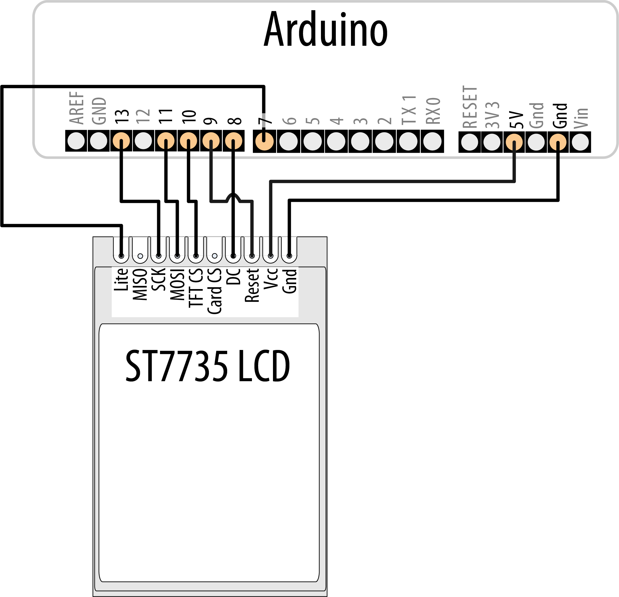
Wiring an ST7735 LCD display to Arduino
The code sets up the #defines for the pins that are not defined by your board, and then initializes an instance of Adafruit_ST7735 as the object tft. Depending on what board you are using and how you’ve wired it, this initialization could vary. For example, you can, in fact, use software SPI and choose different pins for MOSI and SCLK, but this will result in slower performance (and if your LCD board has an SD card included, it won’t work with software SPI):
#define TFT_SCLK 5
#define TFT_MOSI 6
Adafruit_ST7735 tft =
  Adafruit_ST7735(TFT_CS, TFT_DC, TFT_MOSI, TFT_SCLK, TFT_RST);
Within setup(), the sketch initializes the display with a call to initR(). There are many variants of these displays, so be sure to consult the documentation for them (the graphicstest example program included with the library has explanatory comments for many of the supported boards). For example, there is a group of variants that can be identified by the color of the tab on the tape that’s affixed to the screen when you unbox it. The Adafruit 1.8” TFT screen uses INITR_BLACKTAB. The 1.44” display on the HalloWing M0 is the same as the 1.44” green tab display, except that it’s mounted upside down. You can either use INITR_144GREENTAB and setRotation(2) (upside-down portrait mode) as shown in the sketch or just pass INITR_HALLOWING to initR()
After initialization is complete, the sketch draws black over the entire screen, and uses setCursor() to position the cursor on the screen before displaying three lines of text that get progressively larger. In the loop() function, the sketch moves a ball from one side of the screen to the other. It uses a ballDir variable to determine whether the ball moves to the right (1) or to the left (-1). When the ball comes within a ball’s width of one side or the other, it reverses direction.
See Also
Datasheet for the ST7735: https://cdn-shop.adafruit.com/datasheets/ST7735R_V0.2.pdf.
11.11 Control a Monochrome OLED Display
Problem
You want to display single-color graphics on a monochrome OLED such as the ones based on the SSD13xx.
Solution
This recipe uses the Adafruit 128x32 SPI SSD1306 OLED display and the Adafruit SSD1306 library to display text and graphics on the display. The SSD1306 library works with a variety of OLED displays that use this chipset. You can install this library using the Arduino Library Manager (see Chapter 16)
Wire the display to your Arduino as shown in Figure 11-8, and run this sketch, which displays some scrolling text followed by a moving ball:

Wiring an SSD13xx OLED display to Arduino
/*
 * OLED SSD13xx sketch
 * Display text and a moving ball on an OLED display.
 */

#include <SPI.h>
#include <Adafruit_GFX.h>
#include <Adafruit_SSD1306.h>

#define WIDTH 128
#define HEIGHT 32

#define OLED_DC     8
#define OLED_CS    10
#define OLED_RESET  9
Adafruit_SSD1306 display(WIDTH, HEIGHT, &SPI, OLED_DC, OLED_RESET, OLED_CS);

#define MODE SSD1306_SWITCHCAPVCC // get display voltage from 3.3V internally

void setup()
{
  Serial.begin(9600);
  if(!display.begin(MODE))
  {
    Serial.println("Could not initialize display");
    while(1); // halt
  }

  showAndScroll("Small",  1);
  showAndScroll("Medium", 2);
  showAndScroll("Large",  3);
}

// Show text and scroll it briefly
void showAndScroll(String text, int textSize)
{
  display.setTextColor(SSD1306_WHITE); // Draw white text
  display.setCursor(0, 0); // Move the cursor to 0,0
  display.clearDisplay();  // clear the screen

  display.setTextSize(textSize);
  display.println(text);
  display.display();

  // Scroll the display right for 3 seconds
  display.startscrollright(0x00, 0x0F);
  delay(3000);
  display.stopscroll();
}

int ballDir = 1;            // Current direction of motion
int ballDiameter = 8;       // Diameter
int ballX = ballDiameter;   // Starting X position
int ballY = ballDiameter*2; // Y position
void loop()
{
  display.clearDisplay();

  // If the ball is approaching the edge of the screen, reverse direction
  if (ballX >= WIDTH - ballDiameter || ballX < ballDiameter)
  {
    ballDir *= -1;
  }

  // Move the ball's X position
  ballX += ballDir;

  // Draw a ball
  display.fillCircle(ballX, ballY, ballDiameter/2, SSD1306_INVERSE);
  display.display();
  delay(25);

  // Erase the ball
  display.fillCircle(ballX, ballY, ballDiameter/2, SSD1306_INVERSE);
  display.display();
}
Discussion
The chip select and data/command pins are defined in the sketch by OLED_CS and OLED_DC. The OLED_RESET pin is used to reset the display. You can use different pins for any of those. The pins used for MOSI and SCLK are dependent on your board (the Uno wiring is shown in the figure, but see “SPI” for other boards).
The wiring in the Solution uses hardware SPI. If you want to use software SPI, you will need to add a #define for each of those pins, wire them up, and use a different form of the constructor:
#define OLED_CLK    5
#define OLED_MOSI   6
Adafruit_SSD1306 display(WIDTH, HEIGHT,
  OLED_MOSI, OLED_CLK, OLED_DC, OLED_RESET, OLED_CS);
The Adafruit library supports a variety of boards that use this chipset, and you’ll need to change your code to match the display you are using. If your display is a different size but also uses SPI, you can probably just change the #defines for WIDTH and HEIGHT. If your display uses I2C instead of SPI, you can connect with fewer wires. You’ll need to connect the reset pin as before, but you’ll then only need to to connect the SCL and SDA pins between the Arduino and the display. You’ll need to modify the sketch to include Wire.h and use a different variant of the initialization:
#include <Wire.h>
#define WIDTH 128
#define HEIGHT 32
#define OLED_RESET 13
Adafruit_SSD1306 display(WIDTH, HEIGHT, &Wire, OLED_RESET);
The initialization of display, gives you an Adafruit_SSD1306 object that you can use to control the display. In setup(), the sketch starts the display in the SSD1306_SWITCHCAPVCC mode (to tell the display to get its voltage internally). After that, the sketch uses the showAndScroll function to display and scroll text in three sizes. This function configures the display to draw in white text, clears the screen and sets the cursor position to the top left. Then it sets the font, draws it on the screen, and calls display.display() to show what you’ve drawn. This is different from how you worked with the color LCD (Recipe 11.10) where anything you drew was immediately displayed. After the text is displayed, the sketch scrolls the screen for 3 seconds.
In the loop(), the sketch draws a ball on the screen and moves it back and forth across the screen. It uses the SSD1306_INVERSE color to alternate the color from white to black each time it’s drawn. Each time through loop(), the sketch increments the ballX variable until it hits the right side of the screen, when it starts decrementing it (until it hits the left wall). It then displays the ball and shows it for a fraction of a second, before erasing it.
You can also use the U8G2 library to generate a similar display. The code is slightly different, but mostly the same. The biggest difference is that instead of drawing on the screen and calling display.display() to update it, the sketch uses the U8G2 library’s page buffer to update the display in stages. To use this, you must first call u8g2.firstPage(), then set up a do-while loop that calls u8g2.nextPage() at the end. Your drawing commands go inside the loop, and U8G2 uses as many times through the loop as is needed to draw the complete screen. U8G2 supports a wide variety of monochrome displays, and there are variants of each display (for example, hardware SPI, software SPI, I2C, and also permutations of the preceding for a variety of framebuffer/pagebuffer sizes). See https://github.com/olikraus/u8g2/wiki/u8g2setupc for a list of supported devices and their corresponding setup functions.
/*
 * u8g2 oled sketch
 * Draw some text, move a ball.
 */
#include <Arduino.h>
#include <U8g2lib.h>
#include <SPI.h>

#define OLED_DC     8
#define OLED_CS    10
#define OLED_RESET  9
U8G2_SSD1306_128X32_UNIVISION_2_4W_HW_SPI u8g2(U8G2_R0, OLED_CS, OLED_DC, OLED_RESET);

u8g2_uint_t displayWidth;

void setup(void)
{
  u8g2.begin();
  u8g2.setFontPosTop();
  displayWidth = u8g2.getDisplayWidth();

  showAndScroll("Small",  u8g2_font_6x10_tf);
  showAndScroll("Medium", u8g2_font_9x15_tf);
  showAndScroll("Large",  u8g2_font_10x20_tf);
}

int ballDir = 1;          // Current direction of motion
int ballRadius = 4;       // Radius
int ballX = ballRadius*2; // Starting X position
int ballY = ballRadius*4; // Y position
void loop(void)
{
  u8g2.firstPage(); // picture loop
  do
  {
    // If the ball is approaching the edge of the screen, reverse direction
    if (ballX >= displayWidth - ballRadius*2 || ballX < ballRadius*2)
    {
      ballDir *= -1;
    }

    ballX += ballDir; // Move the ball's X position
    u8g2.drawDisc(ballX, ballY, ballRadius); // Draw the ball
  } while ( u8g2.nextPage() );
  delay(25);
}

void showAndScroll(String text, uint8_t *font)
{
  for (int i = 0; i < 20; i++)
  {
    u8g2.firstPage(); // picture loop
    do
    {
      u8g2.setFont(font);
      u8g2.drawStr(10 + i, 10, text.c_str());
    } while ( u8g2.nextPage() );
    delay(125);
  }
}
See Also
Documentation for Adafruit OLED displays: https://learn.adafruit.com/monochrome-oled-breakouts
SSD1306 datasheet: https://cdn-shop.adafruit.com/datasheets/SSD1306.pdf