
Remotely Controlling External Devices
10.0 Introduction
The Arduino can interact with almost any device that uses some form of remote control, including TVs, audio equipment, cameras, garage doors, appliances, and toys. Most remote controls work by sending digital data from a transmitter to a receiver using infrared light (IR) or wireless radio technology. Different protocols (signal patterns) are used to translate key presses into a digital signal, and the recipes in this chapter show you how to use commonly found remote controls and protocols.
An IR remote works by turning an LED on and off in patterns to produce unique codes. The codes are typically 12 to 32 bits (pieces of data). Each key on the remote is associated with a specific code that is transmitted when the key is pressed. If the key is held down, the remote usually sends the same code repeatedly, although some remotes (e.g., NEC) send a special repeat code when a key is held down. For Philips RC-5 or RC-6 remotes, a bit in the code is toggled each time a key is pressed; the receiver uses this toggle bit to determine when a key is pressed a second time. You can read more about the technologies used in IR remote controls at https://www.sbprojects.net/knowledge/ir/index.php.
The IR recipes here use a low-cost IR receiver module to detect the signal and provide a digital output that the Arduino can read. The digital output is then decoded by a library called IRremote, which was written by Ken Shirriff and can be installed using the Arduino IDE library manager (see Chapter 16).
The same library is used in the recipes in which Arduino sends commands to act like a remote control.
Remote controls using wireless radio technology are more difficult to emulate than IR controls. However, the button contacts on these controls can be activated by Arduino. The recipes using wireless remotes simulate button presses by closing the button contacts circuit inside the remote control. With wireless remotes, you may need to take apart the remote control and connect wires from the contacts to Arduino to be able to use these devices. Components called optocouplers are used to provide electrical separation between Arduino and the remote control. This isolation prevents voltages from Arduino from harming the remote control, and vice versa.
Optocouplers (also called optoisolators) enable you to safely control another circuit that may be operating at different voltage levels from Arduino. As the “isolator” part of the name implies, optoisolators provide a way to keep things electrically separated. These devices contain an LED, which can be controlled by an Arduino digital pin. The light from the LED in the optocoupler shines onto a light-sensitive transistor. Turning on the LED causes the transistor to conduct, closing the circuit between its two connections—the equivalent of pressing a switch.
10.1 Responding to an Infrared Remote Control
Problem
You want to respond to any key pressed on a TV or other remote control.
Solution
Arduino responds to IR remote signals using a device called an IR receiver module. Common devices are the TSOP38238, TSOP4838, PNA4602, and TSOP2438. The first three have the same connections, so the circuit is the same; the TSOP2438 has the +5V and Gnd pins reversed. Check the datasheet for your device to ensure that you connect it correctly.
This recipe uses the IRremote library, which you can install with the Library Manager. Connect the IR receiver module according to your datasheet. The Arduino wiring in Figure 10-1 is for the TSOP38238/TSOP4838/PNA4602 devices.
This sketch will toggle the built-in LED when any button on an infrared remote control is pressed:
/*
  IR_remote_detector sketch
  An IR remote receiver is connected to pin 2.
  The built-in LED toggles each time a button on the remote is pressed.
 */

#include <IRremote.h>           // adds the library code to the sketch

const int irReceiverPin = 2;    // pin the receiver is connected to
const int ledPin = LED_BUILTIN;

IRrecv irrecv(irReceiverPin);   // create an IRrecv object
decode_results decodedSignal;   // stores results from IR detector

void setup()
{
  pinMode(ledPin, OUTPUT);
  irrecv.enableIRIn();          // Start the receiver object
}

bool lightState = LOW;          // keep track of whether the LED is on
unsigned long last = millis();  // remember when we last received an IR message

void loop()
{
  if (irrecv.decode(&decodedSignal) == true) // this is true if a message has
                                             // been received
  {
    if (millis() - last > 250) {       // has it been 1/4 sec since last message?
      if (lightState == LOW)
        lightState = HIGH;
      else
        lightState = LOW;
      lightState = lightState ;              // Yes: toggle the LED
      digitalWrite(ledPin, lightState);
    }
    last = millis();
    irrecv.resume();                         // watch out for another message
  }
}

Connecting an infrared receiver module
Warning
If you are using a 3.3V board that is not 5 volt-tolerant, you should power the infrared receiver from 3.3V instead of 5V.
Discussion
The IR receiver converts the IR signal to digital pulses. These are a sequence of ones and zeros that correspond to buttons on the remote. The IRremote library decodes these pulses and provides a numeric value for each key (the actual values that your sketch will receive are dependent on the specific remote control you use).
#include <IRremote.h> at the top of the sketch makes the library code available to your sketch, and the line IRrecv irrecv(irReceiverPin); creates an IRrecv object named irrecv to receive signals from an IR receiver module connected to irReceiverPin (pin 2 in the sketch). Chapter 16 has more on using libraries.
You use the irrecv object to access the signal from the IR receiver. You can give it commands to look for and decode signals. The decoded responses provided by the library are stored in a variable named decode_results. The receiver object (irrecv) is started in setup with the line irrecv.enableIRIn();. The results are checked in loop by calling the function irrecv.decode(&decodedSignal).
The decode function returns true if there is data, which will be placed in the decodedSignal variable. Recipe 2.11 explains how the ampersand symbol is used in function calls where parameters are modified so that information can be passed back.
If a remote message has been received, the code toggles the LED (flips its state) if it is more than one-quarter of a second since the last time it was toggled (otherwise, the LED will get turned on and off quickly by remotes that send codes more than once when you press the button, and may appear to be flashing randomly).
The decodedSignal variable will contain a value associated with a key. This value is ignored in this recipe (although it is used in the next recipe)—you can print the value by adding to the sketch the Serial.println line highlighted in the following code (you will also need to add Serial.begin(9600); in the setup function):
if (irrecv.decode(&decodedSignal) == true) // this is true if a message has
                                           // been received
{
 if (millis() - last > 250) {     // has it been 1/4 sec since last message
   Serial.println(decodedSignal.value);
The library needs to be told to continue monitoring for signals, and this is achieved with the line irrecv.resume();.
This sketch flashes an LED when any button on the remote control is pressed, but you can control other things—for example, you can use a servo motor to dim a lamp (for more on controlling physical devices, see Chapter 8).
10.2 Decoding Infrared Remote Control Signals
Problem
You want to detect a specific key pressed on a TV or other remote control.
Solution
This sketch uses remote control key presses to adjust the brightness of an LED. The code prompts for remote control keys 0 through 4 when the sketch starts. These codes are stored in Arduino memory (RAM), and the sketch then responds to these keys by setting the brightness of an LED to correspond with the button pressed, with 0 turning the LED off and 1 through 4 providing increased brightness:
/*
 * RemoteDecode sketch
 * Infrared remote control signals are decoded to control LED brightness.
 * The values for keys 0-4 are detected and stored when the sketch starts.
 * Key 0 turns the LED off; brightness increases in steps with keys 1-4.
 */

#include <IRremote.h>           // IR remote control library

const int irReceivePin = 2;     // pin connected to IR detector output
const int ledPin       = 9;     // LED is connected to a PWM pin

const int numberOfKeys = 5;     //  5 keys are learned (0 through 4)
long irKeyCodes[numberOfKeys];  // holds the codes for each key

IRrecv irrecv(irReceivePin);    // create the IR library
decode_results results;         // IR data goes here

void setup()
{
  Serial.begin(9600);
  while(!Serial); // Needed for Leonardo and ARM boards
  pinMode(irReceivePin, INPUT);
  pinMode(ledPin, OUTPUT);
  irrecv.enableIRIn();              // Start the IR receiver
  learnKeycodes();                  // learn remote control key  codes
  Serial.println("Press a remote key");
}

void loop()
{
  long key;
  int  brightness;

  if (irrecv.decode(&results))
  {
    // here if data is received
    irrecv.resume();
    key = convertCodeToKey(results.value);
    if(key >= 0)
    {
      Serial.print("Got key ");
      Serial.println(key);
      brightness = map(key, 0,numberOfKeys-1, 0, 255);
      analogWrite(ledPin, brightness);
    }
  }
}

/*
 * get remote control codes
 */
void learnKeycodes()
{
  while(irrecv.decode(&results))   // empty the buffer
    irrecv.resume();

  Serial.println("Ready to learn remote codes");
  long prevValue = -1;
  int i=0;
  while(i < numberOfKeys)
  {
    Serial.print("press remote key ");
    Serial.print(i);
    while(true)
    {
      if(irrecv.decode(&results))
      {
        if(results.value != -1 &&
           results.decode_type != UNKNOWN &&
           results.value != prevValue)
        {
          showReceivedData();
          Serial.println(results.value);
          irKeyCodes[i] = results.value;
          i = i + 1;
          prevValue = results.value;
          irrecv.resume(); // Receive the next value
          break;
        }
        irrecv.resume(); // Receive the next value
      }
    }
  }
  Serial.println("Learning complete");
}

/*
 * converts a remote protocol code to a logical key code
 * (or -1 if no digit received)
 */
int convertCodeToKey(long code)
{
  for(int i=0; i < numberOfKeys; i++)
  {
    if(code == irKeyCodes[i])
    {
      return i; // found the key so return it
    }
  }
  return -1;
}

/*
 * display the protocol type and value
 */
void showReceivedData()
{
  if (results.decode_type == UNKNOWN)
  {
    Serial.println("-Could not decode message");
  }
  else
  {
    if (results.decode_type == NEC) {
      Serial.print("- decoded NEC: ");
    }
    else if (results.decode_type == SONY) {
      Serial.print("- decoded SONY: ");
    }
    else if (results.decode_type == RC5) {
      Serial.print("- decoded RC5: ");
    }
    else if (results.decode_type == RC6) {
      Serial.print("- decoded RC6: ");
    }
    Serial.print("hex value = ");
    Serial.println( results.value, HEX);
  }
}
Discussion
This solution is based on the IRremote library; see this chapter’s introduction for details.
The sketch starts the remote control library with the following code:
irrecv.enableIRIn(); // Start the IR receiver
It then calls the learnKeyCodes function to prompt the user to press keys 0 through 4. The code for each key is stored in an array named irKeyCodes. After all the keys are detected and stored, the loop code waits for a key press and checks if this was one of the digits stored in the irKeyCodes array. If so, the value is used to control the brightness of an LED using analogWrite.
Note
See Recipe 5.7 for more on using the map function and analogWrite to control the brightness of an LED.
The library should be capable of working with most any IR remote control; it can discover and remember the timings and repeat the signal on command.
You can permanently store the key code values so that you don’t need to learn them each time you start the sketch. Replace the declaration of irKeyCodes with the following lines to initialize the values for each key, and comment out the call to learnKeycodes();. Change the values to coincide with the ones for your remote (these will be displayed in the Serial Monitor when you press keys in the learnKeyCodes function):
long irKeyCodes[numberOfKeys] = {
  0x18E758A7,  //0 key
  0x18E708F7,  //1 key
  0x18E78877,  //2 key
  0x18E748B7,  //3 key
  0x18E7C837,  //4 key
  };
See Also
Recipe 18.1 explains how you can store learned data in EEPROM (nonvolatile memory).
10.3 Imitating Remote Control Signals
Problem
You want to use Arduino to control a TV or other remotely controlled appliance by emulating the infrared signal. This is the inverse of Recipe 10.2—it sends commands instead of receiving them.
Solution
This sketch uses the remote control codes from Recipe 10.2 to control a device (your remote codes are likely to differ so make sure you run that recipe’s solution code and use the values unique to your remote). Five buttons select and send one of five codes. Connect an infrared LED to send the signal as shown in Figure 10-2:
/*
 * irSend sketch
 * this code needs an IR LED connected to pin 3
 * and 5 switches connected to pins 6 - 10
 */

#include <IRremote.h>       // IR remote control library

const int numberOfKeys = 5;
const int firstKey = 6;   // the first pin of the 5 sequential pins connected
                          // to buttons
bool buttonState[numberOfKeys];
bool lastButtonState[numberOfKeys];
long irKeyCodes[numberOfKeys] = {
  0x18E758A7,  //0 key
  0x18E708F7,  //1 key
  0x18E78877,  //2 key
  0x18E748B7,  //3 key
  0x18E7C837,  //4 key
};

IRsend irsend;

void setup()
{
  for (int i = 0; i < numberOfKeys; i++) {
    buttonState[i] = true;
    lastButtonState[i] = true;
    int physicalPin=i + firstKey;
    pinMode(physicalPin, INPUT_PULLUP);  // turn on pull-ups
  }
  Serial.begin(9600);
}

void loop() {
  for (int keyNumber=0; keyNumber<numberOfKeys; keyNumber++)
  {
    int physicalPinToRead = keyNumber + firstKey;
    buttonState[keyNumber] = digitalRead(physicalPinToRead);
    if (buttonState[keyNumber] != lastButtonState[keyNumber])
    {
      if (buttonState[keyNumber] == LOW)
      {
        irsend.sendSony(irKeyCodes[keyNumber], 32);
        Serial.println("Sending");
      }
      lastButtonState[keyNumber] = buttonState[keyNumber];
    }
  }
}
Note
You won’t see anything when the codes are sent because the light from the infrared LED isn’t visible to the naked eye.
However, you can verify that an infrared LED is working with a digital camera—you should be able to see it flashing in the camera’s LCD viewfinder.

Buttons and LED for IR sender
Discussion
Arduino controls the device by flashing an IR LED to duplicate the signal that would be sent from your remote control. This requires an IR LED. The specifications are not critical; see Appendix A for suitable components.
The IR library handles the translation from numeric code to IR LED flashes. You need to create an object for sending IR messages. The following line creates an IRsend object that will control the LED on pin 3 (you are not able to specify which pin to use; this is hardcoded within the library):
IRsend irsend;
Note
Depending on which board you are using, the IRRemote library may require a different pin for the infrared LED. For example, Teensy 3.x boards use pin 5. See the README for the IRRemote library at https://github.com/z3t0/Arduino-IRremote. If your board uses a pin that overlaps with the range of pins used for the buttons (pins 6-10 in the Solution sketch), you may need to change the range of pins.
The code uses an array (see Recipe 2.4) called irKeyCodes to hold the range of values that can be sent. It monitors five switches to see which one has been pressed and sends the relevant code in the following line:
irsend.sendSony(irKeyCodes[keyNumber], 32);
The irSend object has different functions for various popular infrared code formats, so check the library documentation if you are using one of the other remote control formats. You can use Recipe 10.2 if you want to display the format used in your remote control.
The sketch passes the code from the array, and the number after it tells the function how many bits long that number is. The 0x at the beginning of the numbers in the definition of irKeyCodes at the top of the sketch means the codes are written in hex (see Chapter 2 for details about hex numbers). Each character in hex represents a 4-bit value. The codes here use eight characters, so they are 32 bits long.
The LED is connected with a current-limiting resistor (see the introduction to Chapter 7).
If you need to increase the sending range, you can use multiple LEDs or select one with greater output.
See Also
Chapter 7 provides more information on controlling LEDs.
Mitch Altman’s TV-B-Gone is a clever remote control application; see https://learn.adafruit.com/tv-b-gone-kit for construction details.
10.4 Controlling a Digital Camera
Problem
You want Arduino to control a digital camera to take pictures under program control. You may want to do time lapse photography or take pictures triggered by an event detected by the Arduino.
Solution
There are a few ways to do this. If your camera has an infrared remote, use Recipe 10.2 to learn the relevant remote codes and Recipe 10.3 to get Arduino to send those codes to the camera.
If your camera doesn’t have an infrared remote but does have a socket for a wired remote, you can use this recipe to control the camera.
Warning
A camera shutter connector, usually called a TRS (tip, ring, sleeve) connector, typically comes in 2.5 mm or 3.5 mm sizes, but the length and shape of the tip may be nonstandard. The safest way to get the correct plug is to buy a cheap wired remote switch for your model of camera and modify that or buy an adapter cable from a specialist supplier (Google “TRS camera shutter”).
You connect the Arduino to a suitable cable for your camera using optocouplers, as shown in Figure 10-3.
This sketch takes 10 pictures, one every 20 seconds:
/*
 * camera sketch
 * takes 20 pictures with a digital camera
 * using pin 4 to trigger focus
 * pin 3 to trigger the shutter
 */

int focus = 4;          // optocoupler attached to focus
int shutter = 3;        // optocoupler attached to shutter
long exposure = 250;    // exposure time in milliseconds
long interval = 10000;  // time between shots, in milliseconds

void setup()
{
  pinMode(focus, OUTPUT);
  pinMode(shutter, OUTPUT);
  for (int i=0; i<20; i++)  // camera will take 20 pictures
  {
    takePicture(exposure);       // takes picture
    delay(interval);             // wait to take the next picture
  }
}

void loop()
{
                  // once it's taken 20 pictures it is done,
                  // so loop is empty
                  // but loop still needs to be here or the
                  // sketch won't compile
}

void takePicture(long exposureTime)
{
  int wakeup = 10;      // camera will take some time to wake up and focus
                        // adjust this to suit your camera

  digitalWrite(focus, HIGH);     // wake the camera and focus
  delay(wakeup);                 // wait for it to wake up and focus
  digitalWrite(shutter, HIGH);   // open the shutter
  delay(exposureTime);           // wait for the exposure time
  digitalWrite(shutter, LOW);    // release shutter
  digitalWrite(focus, LOW);      // release the focus
}
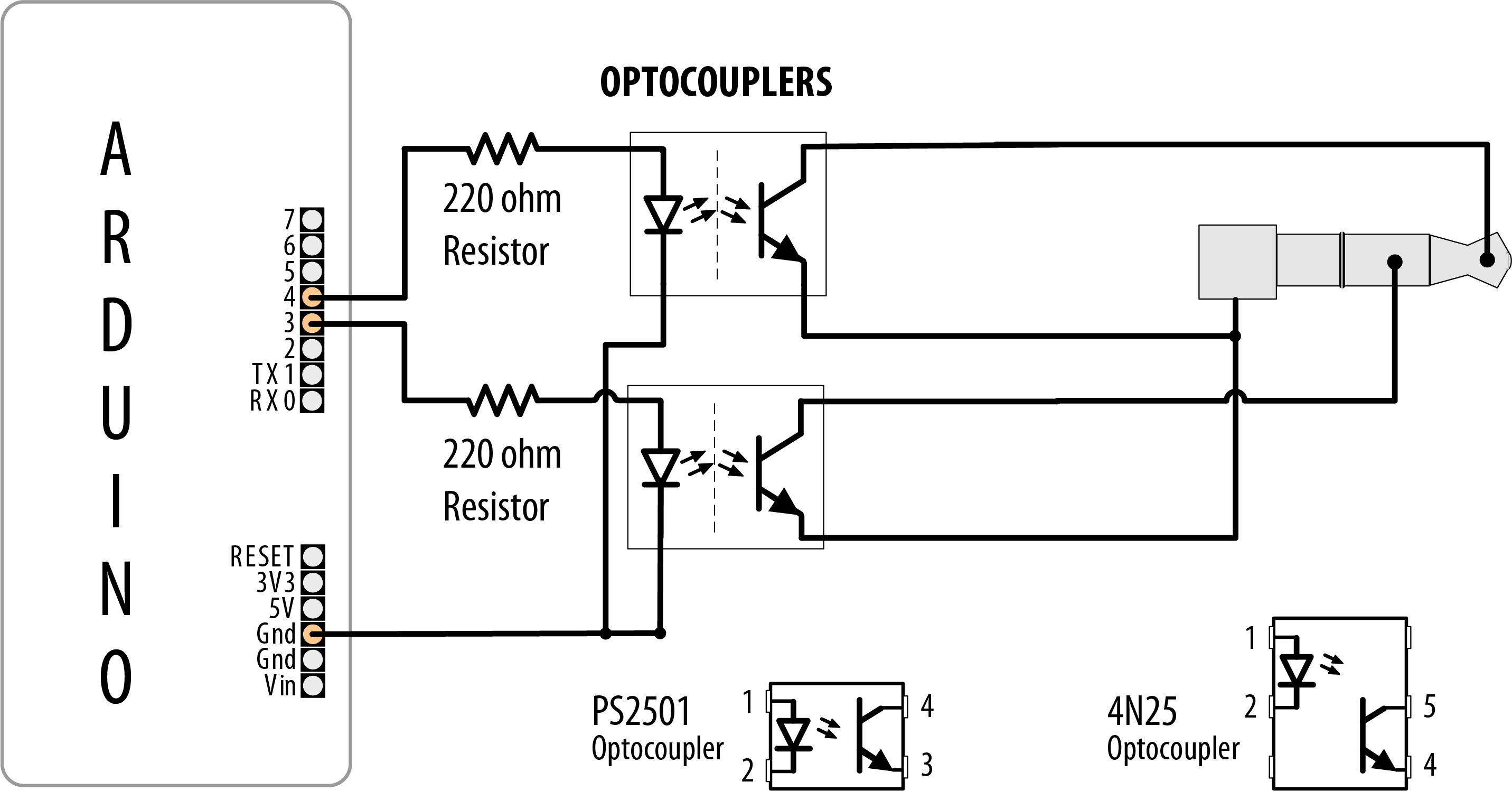
Using optocouplers with a TRS camera connector
Discussion
It’s not advisable to connect Arduino pins directly to a camera—the voltages may not be compatible and you risk damaging your Arduino or your camera. Optocouplers are used to isolate Arduino from your camera; see the introduction of this chapter for more about these devices.
You will need to check the user manual for your camera to identify the correct TRS connector to use.
You may need to change the order of the pins turning on and off in the takePicture function to get the behavior you want. For a Canon camera to do bulb exposures, you need to turn on the focus, then open the shutter without releasing the focus, then release the shutter, and then release the focus (as in the sketch). To take a picture and have the camera calculate the exposure, press the focus button, release it, and then press the shutter.
See Also
If you want to control aspects of a camera’s operation, have a look at the Canon Hack Development Kit at https://chdk.fandom.com/wiki/CHDK.
Also see The Canon Camera Hackers Manual: Teach Your Camera New Tricks by Berthold Daum (Rocky Nook).
You can control a GO PRO camera using an Arduino with WiFi using the library at
https://github.com/agdl/GoPRO/
It is also possible to control video cameras in a similar fashion using LANC. See https://github.com/Julusian/arduino-lanc for a library that supports this feature.
There is also an Arduino shield for controlling high end Black Magic Design video equipment, including cameras using their open protocol. See https://www.blackmagicdesign.com/uk/products/blackmagicursamini/liveproduction for more details.
10.5 Controlling AC Devices by Hacking a Remote-Controlled Switch
Problem
You want to safely switch AC line currents on and off to control lights and appliances using a remote controlled switch.
Solution
Arduino can trigger the buttons of a remote controlled switch using an optocoupler. This may be necessary for remotes that use wireless instead of infrared technology. This technique can be used for almost any remote control. Hacking a remote is particularly useful to isolate potentially dangerous AC voltages from you and Arduino because only the battery-operated controller is modified.
Warning
Opening the remote control will void the warranty and can potentially damage the device. The infrared recipes in this chapter are preferable because they avoid modifying the remote control.
If you want to use this recipe to control a switch, but you want to keep using the remote control, consider purchasing a spare remote control for hacking. Most manufacturers will be happy to sell you a spare (but make sure you choose the right frequency for the variant of appliance, light, or outlet you want to control). After you receive the spare, you may need to configure the channel that it uses.
Open the remote control and connect the optocoupler so that the photo-emitter (pins 1 and 2 in Figure 10-4) is connected to Arduino and the photo-transistor (pins 3 and 4) is connected across the remote control contacts.
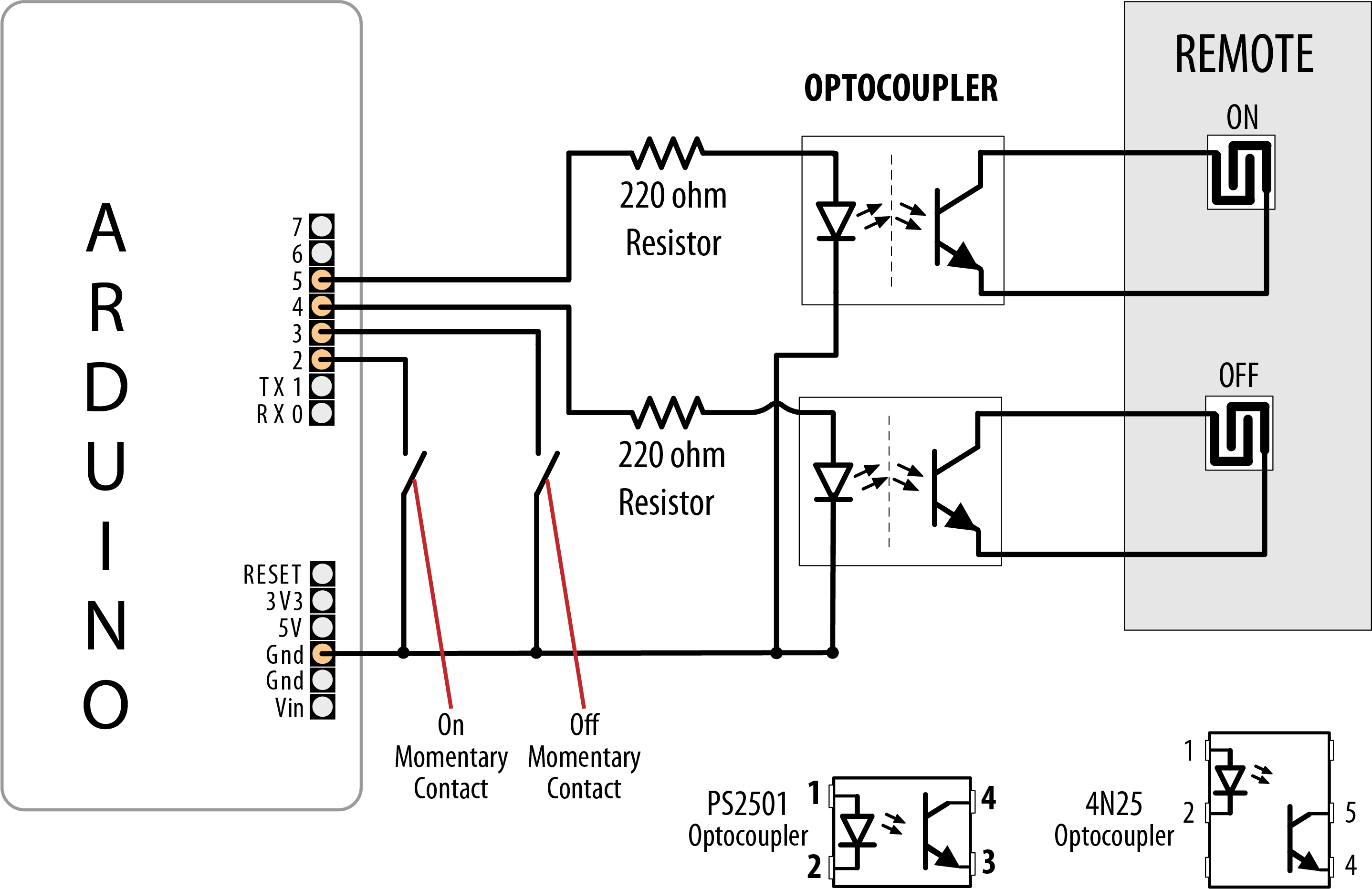
Optocouplers connected to remote control contacts
This sketch uses momentary contact switches (push and release) to turn the remote ON and OFF buttons:
/*
 * OptoRemote sketch
 * Switches connected to pins 2 and 3 turns a remote device on and off
 * using optocouplers.
 * The outputs are pulsed for at least half a second when a switch is pressed
 */
const int onSwitchPin  = 2;         // input pin for the On switch
const int offSwitchPin = 3;         // input pin for the Off switch
const int remoteOnPin  = 4;         // output pin to turn the remote on
const int remoteOffPin = 5;         // output pin to turn the remote off
const int PUSHED       = LOW;       // value when button is pressed

void setup() {
  pinMode(remoteOnPin, OUTPUT);
  pinMode(remoteOffPin, OUTPUT);
  pinMode(onSwitchPin, INPUT_PULLUP);  // turn on internal pull-up on the inputPins
  pinMode(offSwitchPin, INPUT_PULLUP);
}

void loop(){
  int val = digitalRead(onSwitchPin);  // read input value
  // if the switch is pushed then switch on if not already on
  if(val == PUSHED)
  {
    pulseRemote(remoteOnPin);
  }

  val = digitalRead(offSwitchPin);  // read input value
  // if the switch is pushed then switch off if not already off
  if(val == PUSHED)
  {
    pulseRemote(remoteOffPin);
  }
}

// turn the optocoupler on for half a second to blip the remote control button
void pulseRemote(int pin)
{
  digitalWrite(pin, HIGH);     // turn the optocoupler on
  delay(500);                  // wait half a second
  digitalWrite(pin, LOW);      // turn the optocoupler off
}
Discussion
The switches in most remote controls consist of interleaved bare copper traces with a conductive button that closes a connection across the traces when pressed. Less common are controls that contain conventional push switches; these are easier to use as the legs of the switches provide a convenient connection point.
Note
Although the original remote button and the optocoupler can be used together—the switching action will be performed if either method is activated (pressing the button or turning on the optocoupler), the wires tethered to Arduino can make this inconvenient.
The transistor in the optocoupler will only allow electricity to flow in one direction, so if it doesn’t work the first time, try switching the transistor-side connections over and see if that fixes it.
Some remotes have one side of all of the switches connected together (usually to the ground of that circuit). You can trace the connections on the board to check for this or use a multimeter to see what the resistance is between the traces on different switches. If traces have common connections, it is only necessary to connect one wire to each common group. Fewer traces are easier because connecting the wires can be fiddly if the remote is small.
Optocouplers are used in Recipe 10.4, so check that recipe out for an example of how they are used in a circuit.
The remote control may have multiple contacts corresponding to each button. You may need more than one optocoupler for each button position to connect the contacts. Figure 10-5 shows three optocouplers that are controlled from a single Arduino pin.
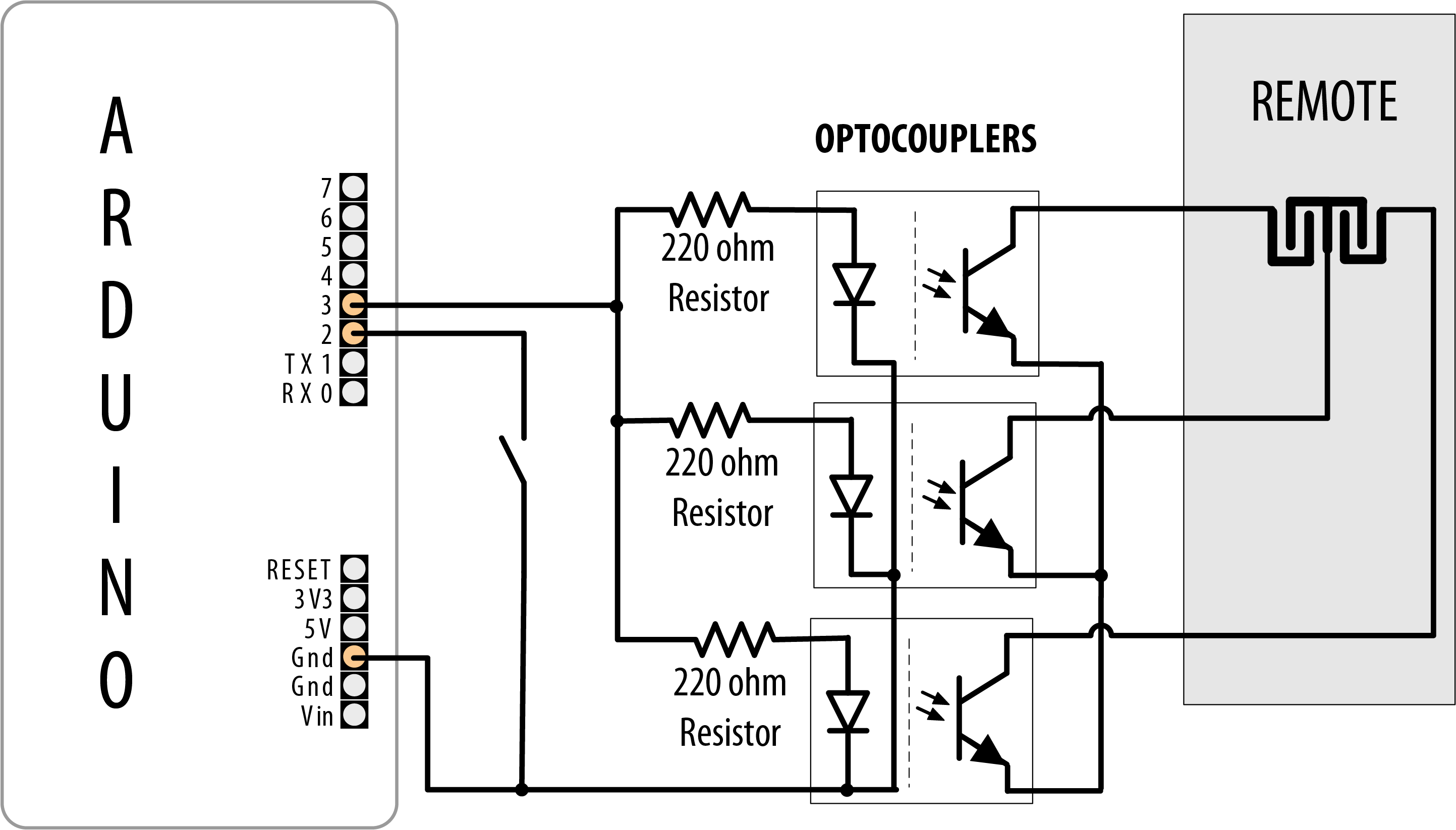
Multiple optocouplers connected to a single remote control button
See Also
Another approach to controlling AC line currents is to use an isolated relay that can be switched on and off directly from Arduino pins, such as the Digital Loggers IoT Power Relay, available from Adafruit (part 2935) or SparkFun (part 14236). The IoT Power Relay is a great alternative to the now-discontinued PowerSwitch Tail.