
WiFi and Ethernet
15.0 Introduction
Want to share your sensor data? Let other people take control of your Arduino’s actions? Your Arduino can communicate with a broader world over Ethernet and WiFi networks. This chapter describes the many ways you can use Arduino with the Internet. It has examples that demonstrate how to build and use web clients and servers, and it shows how to use the most common Internet communication protocols with Arduino.
The Internet allows a client (e.g., a web browser) to request information from a server (a web server or other Internet service provider). This chapter contains recipes showing how to make an Internet client that retrieves information from a web service. Other recipes in this chapter show how Arduino can be an Internet server that provides information to clients using Internet protocols and can even act as a web server that creates pages for viewing in web browsers.
The Arduino Ethernet and WiFi libraries support a range of methods (protocols) that enable your sketches to be an Internet client or a server. The libraries use a suite of standard Internet protocols, and most of the low-level plumbing is hidden. Getting your clients or servers up and running and doing useful tasks will require some understanding of the basics of network addressing and protocols, and you may want to consult one of the many references available online or one of these introductory books:
-
Head First Networking by Al Anderson and Ryan Benedetti (O’Reilly)
-
Network Know-How: An Essential Guide for the Accidental Admin by John Ross (No Starch Press)
-
Making Things Talk by Tom Igoe (Make Community)
Here are some of the key concepts in this chapter. You may want to explore them in more depth than is possible here:
- Ethernet
-
This is the low-level signaling layer providing basic physical message-passing capability. Source and destination addresses for these messages are identified by a Media Access Control (MAC) address. Your Arduino sketch defines a MAC address value that must be unique on your network.
- WiFi
-
In many respects, WiFi is a functional replacement for Ethernet. Like Ethernet, WiFi provides also is a low-level signaling layer, and it also uses MAC addresses to identify devices uniquely on the network. You won’t need to hardcode a MAC address into your sketch because it is embedded in the radio. In terms of where WiFi and Ethernet live in the various layers that make up a networking stack, they are at the bottom, so to all intents and purposes, they are interchangeable with each other, at least from the Arduino programmer’s viewpoint. The setup and initialization code is slightly different between WiFi and Ethernet, but once the connection is up and running, the rest of the code can be identical.
- TCP and IP
-
Transmission Control Protocol (TCP) and Internet Protocol (IP) are core Internet protocols built above Ethernet or WiFi. They provide a message-passing capability that operates over the global Internet. TCP/IP messages are delivered through unique IP addresses for the sender and receiver. A server on the Internet uses a numeric label (address) that no other server will have so that it can be uniquely identified. This address consists of four bytes, usually represented with dots separating the bytes (e.g., 207.241.224.2 was, at the time of this writing, an IP address used by the Internet Archive). The Internet uses the Domain Name System (DNS) service to translate the host name (
google.com) to the numeric IP address. - Local IP addresses
-
If you have more than one computer connected to the Internet on your home network using a broadband router or gateway, each computer probably uses a local IP address that is provided by your router. The local address is created using a Dynamic Host Configuration Protocol (DHCP) service in your router, which the Arduino Ethernet and WiFi libraries can use to obtain IP addresses from the router.
Web requests from a web browser and the resultant responses use Hypertext Transfer Protocol (HTTP) messages. For a web client or server to respond correctly, it must understand and respond to HTTP requests and responses. Many of the recipes in this chapter use this protocol, and referring to one of the references listed earlier for more details will help with understanding how these recipes work in detail.
Web pages are usually formatted using Hypertext Markup Language (HTML). Although it’s not essential to use HTML if you are making an Arduino web server, as Recipe 15.11 illustrates, the web pages you serve can use this capability.
Extracting data from a web server page intended to be viewed by people using a web browser can be a little like finding a needle in a haystack because of all the extraneous text, images, and formatting tags used on a typical page. This task can be simplified by using the Stream parsing functionality in Arduino to find particular sequences of characters and to get strings and numeric values from a stream of data. In fact, it is unwise and potentially dangerous to create any automated system that makes request to web servers that were intended to be used by humans. For example, if you were to accidentally (or intentionally) create code that performed a Google search every 5 seconds, your IP address may be blocked from accessing Google services until you stop. If you are on an office or school network where all the devices on your network are behind a gateway, that gateway’s IP address may be blocked, which would be extremely inconvenient for others. For this reason, it is best to use a documented Web API, which you’ll see done throughout this chapter. An API allows you to receive web responses in a leaner format than HTML, such as JSON, XML, or CSV. This lets you limit the amount of data you are requesting, and using API arguments, you can narrow those requests down to just the data you need. Most important, using an API and abiding by its rules allows you to work within agreed-upon parameters that the web server’s operator has established.
15.1 Connecting to an Ethernet Network
Problem
You want to connect Arduino to an Ethernet network using an Ethernet module such as the Arduino Ethernet shield or the Adafruit Ethernet FeatherWing (which connects to boards in the Adafruit Feather form factor).
Solution
This sketch uses the Ethernet library that is included with the Arduino IDE to request some information from the Internet Archive. The library supports a number of Ethernet modules. In order for this sketch to work correctly, you will need to know several things about your network: the DNS server IP address, the default gateway IP address, and one available static IP address (an address that is outside the pool of automatically assigned addresses). This information can be found in your network router’s configuration utility, which is typically accessed via a web browser.
/** Ethernet Web Client sketch* Connects to the network without DHCP, using* hardcoded IP addresses for device.*/#include <SPI.h>#include <Ethernet.h>bytemac[]={0xDE,0xAD,0xBE,0xEF,0xFE,0xED};// Must be uniqueIPAddressip(192,168,1,177);// Must be a valid address for your networkcharserverName[]="archive.org";EthernetClientclient;Stringrequest="GET /advancedsearch.php?q=arduino&fl%5B%5D=description""&rows=1&sort%5B%5D=downloads+desc&output=csv#raw HTTP/1.0";voidsetup(){Serial.begin(9600);while(!Serial);// for Leonardo and 32-bit boardsEthernet.begin(mac,ip);delay(1000);// give the Ethernet hardware a second to initializeSerial.println("Connecting to server...");intret=client.connect(serverName,80);if(ret==1){Serial.println("Connected");client.println(request);client.("Host: ");client.println(serverName);client.println("Connection: close");client.println();// Send the terminating blank line that HTTP requires}else{Serial.println("Connection failed, error was: ");Serial.(ret,DEC);}}voidloop(){if(client.available()){charc=client.read();Serial.(c);// echo all data received to the Serial Monitor}if(!client.connected()){Serial.println();Serial.println("Disconnecting.");client.stop();while(1);// halt}}
Discussion
This sketch provides some simple code to help you confirm that your Ethernet board is connected and configured correctly, and that it can reach remote servers. It uses the Internet Archive API to search for Arduino by using the parameter q=arduino in the request. That request variable contains the request method (GET), the path of the request (/advancedsearch.php), and the query string, which includes everything from ? to the space before the HTTP protocol (HTTP/1.0). After the search term, the query string specifics just one field in the response (fl%5B%5D=description, or fl[]=description unescaped), and only one result (rows=1). Because it sorts by number of downloads in descending order (sort%5B%5D=downloads+desc), that one result is the #1 downloaded Arduino resource on Archive.org. The sketch uses the HTTP 1.0 protocol rather than the HTTP 1.1 protocol because HTTP 1.1 servers may use features that make your sketch’s life more complicated. For example, HTTP 1.1 clients must support chunked responses, which causes the server to split the responses into one or more chunk separated by a delimiter that represents the length of each chunk. It’s up to the server as to whether it sends a chunked response, but if the client specifies HTTP/1.0 in the request, the server knows to not use HTTP/1.1 features.
Note
Because Arduino uses SPI to communicate with the Ethernet hardware, the line at the top of the sketch that includes <SPI.h> is required for the Ethernet library to function properly.
There are several addresses that you may need to configure for the sketch to successfully connect and display the results of the search on the Serial Monitor:
-
byte mac[] = { 0xDE, 0xAD, 0xBE, 0xEF, 0xFE, 0xED }; -
The MAC address uniquely identifies your Ethernet shield. Every network device must have a different MAC address, and if you use more than one Arduino shield on your network, each must use a different address. Current Ethernet shields have a MAC address printed on a sticker on the underside of the board. If you have a single Ethernet shield, you don’t need to change the MAC address, unless by some strange coincidence, you happen to have a device on your network that uses the MAC address used in this example. You cannot make up any MAC address you want, because most MAC addresses are assigned by a central authority. However, there is a defined set of MAC addresses that you can use for local addressing, and will work fine as long as you don’t assign the same address to multiple devices.
MAC addresses consist of a series of bytes (called octets), and in the sketch, they are expressed as a pair of nybbles (four bits, a half-byte that can be represented by a single hexadecimal character). For the first octet (0xDE), the high nybble is D and the low is E. If the second nybble of the first octet is 2, 6, A, or E, you can use it as a local MAC address. But, for example,
{ 0xAD, 0xDE, 0xBE, 0xEF, 0xFE, 0xED }would not be a valid local MAC address because the second nybble of the first octet (D) disqualifies it. So if you are putting multiple devices on the same network and need to create MAC addresses, be sure to follow that rule to avoid surprises. -
IPAddress ip(192, 168, 1, 177); -
The IP address is used to identify something that is communicating on the Internet and must also be unique on your network. The address consists of four bytes, and the range of valid values for each byte depends on how your network is configured. IP addresses are usually expressed with dots separating the bytes—for example, 192.168.1.177. In all the Arduino sketches, commas are used instead of dots because the IPAddress class represents an IP address internally as an array of bytes (see Recipe 2.4).
If your network is connected to the Internet using a router or gateway, you may need to provide the IP address of the gateway when you call the
Ethernet.beginfunction. If you don’t the Ethernet library replaces the last digit (177 in this example) with 1 to determine the gateway and DNS addresses, which is a good guess most of the time. You can find the address of the gateway and DNS server in the configuration utility for your router, which is often web-based. Add two lines after the IP and server addresses at the top of the sketch with the address of your DNS server and gateway:// add if needed by your router or gateway IPAddress dns_server(192, 168, 1, 2); // The address of your DNS server IPAddress gateway(192, 168, 1, 254); // your gateway address
And change the first line in
setupto include the gateway address in the startup values for Ethernet:Ethernet.begin(mac, ip, dns_server, gateway);
The default gateway’s job is to route network packets to and from the world outside your network, and the DNS server’s job is to convert a server name like
archive.orginto an IP address like207.241.224.2so the Ethernet library knows the address of the server you are trying to reach. Behind the scenes, the Ethernet library will pass that IP address to your default gateway, which acts like the local post office: it will put your message on the right “truck” needed to get to the next post office between you and your destination. Each post office sends your message along to the next until it reachesarchive.org.
The client.connect function will return 1 if the hostname can be resolved to an IP address by the DNS server and the client can connect successfully. Here are the values that can be returned from client.connect:
1 = success
0 = connection failed
-1 = no DNS server given
-2 = No DNS  records found
-3 = timeout
If the error is –1, you will need to manually configure the DNS server as described earlier in this recipe.
Most Ethernet add-on modules will work without additional configuration. However, in some cases, you need to specify the chip select pin to get the Ethernet module to work correctly. Here is an excerpt from an Ethernet library example sketch that shows some of the possibilities:
  //Ethernet.init(10);  // Most Arduino shields
  //Ethernet.init(5);   // MKR ETH shield
  //Ethernet.init(0);   // Teensy 2.0
  //Ethernet.init(20);  // Teensy++ 2.0
  //Ethernet.init(15);  // ESP8266 with Adafruit Featherwing Ethernet
  //Ethernet.init(33);  // ESP32 with Adafruit Featherwing
If you need to use one of these, you can uncomment it and add it to your sketch. You need to call Ethernet.init before Ethernet.begin. See the documentation for your Ethernet module for more details. When the sketch is running correctly, you’ll see the following output, which displays the HTTP headers followed by a blank line, which is followed by the body of the response. You’ll also see some diagnostic info indicating when the connection is initiated and when the client disconnects from the server:
Connecting to server...
Connected
HTTP/1.1 200 OK
Server: nginx/1.14.0 (Ubuntu)
Date: Sun, 24 Nov 2019 03:36:50 GMT
Content-Type: text/csv;charset=UTF-8
Connection: close
Content-disposition: attachment; filename=search.csv
Strict-Transport-Security: max-age=15724800

"description"
"Arduino The Documentary 2010"

Disconnecting.
See Also
The web reference for the Arduino Ethernet library is at https://www.arduino.cc/en/reference/ethernet.
15.2 Obtaining Your IP Address Automatically
Problem
The IP address you use for the Ethernet shield must be unique on your network and you would like this to be allocated automatically. You want the Ethernet shield to obtain an IP address from a DHCP server.
Solution
This sketch uses a similar configuration process to the one from from Recipe 15.1 but it does not pass an IP address to the Ethernet.begin method:
/** DHCP sketch* Obtain an IP address from the DHCP server and display it*/#include <SPI.h>#include <Ethernet.h>bytemac[]={0xDE,0xAD,0xBE,0xEF,0xFE,0xED};// Must be uniqueEthernetClientclient;voidsetup(){Serial.begin(9600);while(!Serial);// for Leonardo and 32-bit boardsif(Ethernet.begin(mac)==0){Serial.println("Failed to configure Ethernet using DHCP");while(1);// halt}delay(1000);// give the Ethernet hardware a second to initialize}#define MAINTAIN_DELAY 750// Maintain DHCP lease every .75 secondsvoidloop(){staticunsignedlongnextMaintain=millis()+MAINTAIN_DELAY;if(millis()>nextMaintain){nextMaintain=millis()+MAINTAIN_DELAY;intret=Ethernet.maintain();if(ret==1||ret==3){Serial.("Failed to maintain DHCP lease. Error: ");Serial.println(ret);}Serial.("Current IP address: ");IPAddressmyIPAddress=Ethernet.localIP();Serial.println(myIPAddress);}}
Discussion
The major difference from the sketch in Recipe 15.1 is that there is no IP (or gateway or DNS server) address variable. These values are acquired from your DHCP server when the sketch starts. Also there is a check to confirm that the Ethernet.begin statement was successful. This is needed to ensure that a valid IP address has been provided by the DHCP server (network access is not possible without a valid IP address).
When a DHCP server assigns an IP address, your Arduino is given a lease. When the lease expires, the DHCP server may give you the same IP address or it may give you a new one. You must periodically call Ethernet.maintain() to let the DHCP server know you’re still active. If you don’t call it at least once per second, you could lose out on the renewal when the time comes. DHCP lease behavior (length of lease, what the DHCP server does when the lease is renewed) depends on the configuration of your network router. Each time through, this code prints the IP address to the Serial Monitor.
Warning
Using DHCP features will increase your sketch size by a couple of kilobytes of program storage space. If you are low on storage space, you can use a fixed IP address (see Recipe 15.1.
15.3 Sending and Receiving Simple Messages (UDP)
Problem
You want to send and receive simple messages over the Internet.
Solution
This sketch uses the Arduino UDP (User Datagram Protocol) library to send and receive strings. UDP is a simpler, but slightly messier, message protocol compared to TCP. While sending a TCP message will result in an error if a message can’t reach its destination intact, UDP messages may arrive out of order, or not at all, and your sketch won’t receive an error when something goes wrong with delivery. But UDP has less overhead than TCP, and is a good choice when you need to trade speed for reliability. In this simple example, Arduino prints the received string to the Serial Monitor and a string is sent back to the sender saying “acknowledged”:
/** UDPSendReceiveStrings* This sketch receives UDP message strings, prints them to the serial port* and sends an "acknowledge" string back to the sender*/#include <SPI.h>#include <Ethernet.h>#include <EthernetUdp.h>bytemac[]={0xDE,0xAD,0xBE,0xEF,0xFE,0xED};// MAC address to useunsignedintlocalPort=8888;// local port to listen on// buffers for receiving and sending datacharpacketBuffer[UDP_TX_PACKET_MAX_SIZE];// buffer to hold incoming packet,charreplyBuffer[]="acknowledged";// a string to send back// A UDP instance to let us send and receive packets over UDPEthernetUDPUdp;voidsetup(){Serial.begin(9600);// start Ethernet and UDPEthernet.begin(mac);Udp.begin(localPort);}voidloop(){// if there's data available, read a packetintpacketSize=Udp.parsePacket();if(packetSize){Serial.("Received packet of size ");Serial.println(packetSize);// read packet into packetBuffer and get sender's IP addr and port numberUdp.read(packetBuffer,UDP_TX_PACKET_MAX_SIZE);Serial.println("Contents:");Serial.println(packetBuffer);// send a string back to the senderUdp.beginPacket(Udp.remoteIP(),Udp.remotePort());Udp.write(replyBuffer);Udp.endPacket();}maintainLease();// Keep our DHCP connectiondelay(10);}#define MAINTAIN_DELAY 750// Maintain DHCP lease every .75 secondsvoidmaintainLease(){staticunsignedlongnextMaintain=millis()+MAINTAIN_DELAY;if(millis()>nextMaintain){nextMaintain=millis()+MAINTAIN_DELAY;intret=Ethernet.maintain();if(ret==1||ret==3){Serial.("Failed to maintain DHCP lease. Error: ");Serial.println(ret);}Serial.("Current IP address: ");IPAddressmyIPAddress=Ethernet.localIP();Serial.println(myIPAddress);}}
You can test this by running the following Processing sketch on your computer (see “The Processing Development Environment”). The Processing sketch uses the UDP library that you need to install by clicking Sketch>Import Library>Add Library... and then find and select the UDP library by Stephane Cousot. When you run the Arduino sketch, it will display its current IP address. You will need to change the IP address in the Processing sketch on line String ip = "192.168.1.177"; to match the Arduino’s IP address.
// Processing UDP example to send and receive string data from Arduino// press any key to send the "Hello Arduino" messageimporthypermedia.net.*;// the Processing UDP library by Stephane CousotUDPudp;// define the UDP objectvoidsetup(){udp=newUDP(this,6000);// create datagram connection on port 6000//udp.log( true ); // <-- print out the connection activityudp.listen(true);// and wait for incoming message}voiddraw(){}voidkeyPressed(){Stringip="192.168.1.177";// the remote IP addressintport=8888;// the destination portudp.send("Hello World",ip,port);// the message to send}voidreceive(byte[]data){for(inti=0;i<data.length;i++)(char(data[i]));println();}
Discussion
Plug the Ethernet shield into Arduino and connect the Ethernet cable to your computer. Upload the Arduino sketch and run the Processing sketch on your computer. Hit any key to send the “hello Arduino” message. Arduino sends back “acknowledged,” which is displayed in the Processing text window. String length is limited by a constant set in the EthernetUdp.h library file; the default value is 24 bytes, but you can increase this by editing the following line in Udp.h if you want to send longer strings:
#define UDP_TX_PACKET_MAX_SIZE 24
UDP is a simple and fast way to send and receive messages over Ethernet. But it does have limitations—the messages are not guaranteed to be delivered, and on a very busy network some messages could get lost or get delivered in a different order than that in which they were sent. But UDP works well for things such as displaying the status of Arduino sensors—each message contains the current sensor value to display, and any lost messages get replaced by messages that follow.
This sketch demonstrates sending and receiving sensor messages. It receives messages containing values to be written to the analog output ports and replies back to the sender with the values on the analog input pins:
/** UDPSendReceive sketch:*/#include <SPI.h>#include <Ethernet.h>#include <EthernetUDP.h>bytemac[]={0xDE,0xAD,0xBE,0xEF,0xFE,0xED};// MAC address to useunsignedintlocalPort=8888;// local port to listen oncharpacketBuffer[UDP_TX_PACKET_MAX_SIZE];// buffer to hold incoming packet,intpacketSize;// holds received packet sizeconstintanalogOutPins[]={3,5,6,9};// pins 10 and 11 used by Ethernet shield// A UDP instance to let us send and receive packets over UDPEthernetUDPUdp;voidsetup(){Ethernet.begin(mac,ip);Udp.begin(localPort);Serial.begin(9600);Serial.println("Ready");}voidloop(){// if there's data available, read a packetpacketSize=Udp.parsePacket();if(packetSize>0){Serial.("Received packet of size ");Serial.(packetSize);Serial.println(" with contents:");// read packet into packetBuffer and get sender's IP addr and port numberpacketSize=min(packetSize,UDP_TX_PACKET_MAX_SIZE);Udp.read(packetBuffer,UDP_TX_PACKET_MAX_SIZE);for(inti=0;i<packetSize;i++){bytevalue=packetBuffer[i];if(i<4){// only write to the first four analog out pinsanalogWrite(analogOutPins[i],value);}Serial.println(value,DEC);}Serial.println();// tell the sender the values of our analog portssendAnalogValues(Udp.remoteIP(),Udp.remotePort());}//wait a bitdelay(10);}voidsendAnalogValues(IPAddresstargetIp,unsignedinttargetPort){intindex=0;for(inti=0;i<6;i++){intvalue=analogRead(i);packetBuffer[index++]=lowByte(value);// the low byte);packetBuffer[index++]=highByte(value);// the high byte); }}//send a packet back to the senderUdp.beginPacket(targetIp,targetPort);Udp.write(packetBuffer);Udp.endPacket();}
The sketch sends and receives the values on analog ports 0 through 5 using binary data. If you are not familiar with messages containing binary data, see the introduction to Chapter 4, as well as Recipes 4.6 and 4.7, for a detailed discussion on how this is done on Arduino.
The difference here is that the data is sent using Udp.write instead of Serial.write.
Here is a Processing sketch you can use with the preceding sketch. It has six scroll bars that can be dragged with a mouse to set the six analogWrite levels; it prints the received sensor data to the Processing text window. After you set a slider, press any key to send the values to the Arduino.
// Processing UDPTest
// Demo sketch sends & receives data to Arduino using UDP

import hypermedia.net.*;

UDP udp;  // define the UDP object

HScrollbar[] scroll = new HScrollbar[6];  //see: topics/gui/scrollbar

void setup() {
  size(256, 200);
  noStroke();
  for (int i=0; i < 6; i++) // create the scroll bars
    scroll[i] = new HScrollbar(0, 10 + (height / 6) * i, width, 10, 3*5+1);

  udp = new UDP( this, 6000 );  // create datagram connection on port 6000
  udp.listen( true );           // and wait for incoming message
}

void draw()
{
  background(255);
  fill(255);
  for (int i=0; i < 6; i++) {
    scroll[i].update();
    scroll[i].display();
  }
}

void keyPressed()
{
  String ip = "192.168.137.64"; // the remote IP address (CHANGE THIS!)
  int port = 8888;              // the destination port
  byte[] message = new byte[6] ;

  for (int i=0; i < 6; i++) {
    message[i] = byte(scroll[i].getPos());
    println(int(message[i]));
  }
  println();
  udp.send( message, ip, port );
}

void receive( byte[] data )
{
  println("incoming data is:");
  for (int i=0; i < min(6, data.length); i++)
  {
    scroll[i].setPos(data[i]);
    print(i);
    print(":");
    println((int)data[i]);
  }
}

class HScrollbar
{
  int swidth, sheight;    // width and height of bar
  int xpos, ypos;         // x and y position of bar
  float spos, newspos;    // x position of slider
  int sposMin, sposMax;   // max and min values of slider
  int loose;              // how loose/heavy
  Boolean over;           // is the mouse over the slider?
  Boolean locked;
  float ratio;

  HScrollbar (int xp, int yp, int sw, int sh, int l)
  {
    swidth = sw;
    sheight = sh;
    int widthtoheight = sw - sh;
    ratio = (float)sw / (float) widthtoheight;
    xpos = xp;
    ypos = yp-sheight/2;
    spos = xpos + swidth/2 - sheight/2;
    newspos = spos;
    sposMin = xpos;
    sposMax = xpos + swidth - sheight;
    loose = l;
  }

  void update()
  {
    if (over())
    {
      over = true;
    }
    else
    {
      over = false;
    }
    if (mousePressed && over)
    {
      locked = true;
    }
    if (!mousePressed)
    {
      locked = false;
    }
    if (locked)
    {
      newspos = constrain(mouseX-sheight/2, sposMin, sposMax);
    }
    if (abs(newspos - spos) > 1)
    {
      spos = spos + (newspos-spos)/loose;
    }
  }

  int constrain(int val, int minv, int maxv)
  {
    return min(max(val, minv), maxv);
  }

  Boolean over()
  {
    if (mouseX > xpos && mouseX < xpos+swidth &&
      mouseY > ypos && mouseY < ypos+sheight)
    mouseY > ypos && mouseY < ypos+sheight)
      mouseY > ypos && mouseY < ypos+sheight)
    {
      return true;
    }
    else
    {
      return false;
    }
  }

  void display()
  {
    fill(255);
    rect(xpos, ypos, swidth, sheight);
    if (over || locked)
    {
      fill(153, 102, 0);
    }
    else
    {
      fill(102, 102, 102);
    }
    rect(spos, ypos, sheight, sheight);
  }

  float getPos()
  {
    return spos * ratio;
  }

  void setPos(int value)
  {
    spos = value / ratio;
  }
}
15.4 Use an Arduino with Built-In WiFi
Problem
You want to build wireless networking projects with an Arduino board that has a built-in WiFi coprocessor.
Solution
A select number of Arduino boards combine an ARM or AVR processor with a WiFi co-processor in a small form factor. The most current boards are based on the NINA-W102 modules from u-blox, which are powered by an Espressif ESP32 module.
This sketch uses the WiFiNINA library that is available from the Library Manager. It supports the WiFi module that’s built into the Arduino Uno WiFi Rev 2, Nano 33 IoT, MKR 1010, and MKR VIDOR 4000. The Adafruit Airlift modules, such as the breakout board (4201) and shield (4285), are compatible with this recipe, but Adafruit recommends that you use their customized WiFININA library (see https://learn.adafruit.com/adafruit-airlift-breakout/arduino).
To connect to your WiFi network, add YOUR_SSID and password to the sketch where indicated.
/*
 * WiFiNINA Web Client sketch
 * Requests some data from the Internet Archive
 */

#include <SPI.h>
#include <WiFiNINA.h>

const char ssid[] = "YOUR_SSID";
const char password[] = "YOUR_PASSWORD";

WiFiClient client; // WiFi client

char serverName[] = "archive.org";
String request = "GET /advancedsearch.php?q=arduino&fl%5B%5D=description"
                 "&rows=1&sort%5B%5D=downloads+desc&output=csv#raw HTTP/1.0";

bool configureNetwork()
{
  int status = WL_IDLE_STATUS; // WiFistatus

  if (WiFi.status() == WL_NO_MODULE)
  {
    Serial.println("Couldn't find WiFi hardware.");
    return false;
  }
  String fv = WiFi.firmwareVersion();
  if (fv < WIFI_FIRMWARE_LATEST_VERSION)
  {
    Serial.println("Please upgrade the WiFi firmware");
  }
  while (status != WL_CONNECTED)
  {
    Serial.print("Attempting WiFi connection to "); Serial.println(ssid);
    status = WiFi.begin(ssid, password); // Attempt connection until successful
    delay(1000); // Wait 1 second
  }
  return true;
}

void setup()
{
  Serial.begin(9600);
  if (!configureNetwork())
  {
    Serial.println("Stopping.");
    while(1); // halt
  }

  Serial.println("Connecting to server...");
  int ret = client.connect(serverName, 80);
  if (ret == 1)
  {
    Serial.println("Connected");
    client.println(request);
    client.print("Host: "); client.println(serverName);
    client.println("Connection: close");
    client.println();
  }
  else
  {
    Serial.println("Connection failed, error was: ");
    Serial.print(ret, DEC);
  }
}

void loop()
{
  if (client.available())
  {
    char c = client.read();
    Serial.print(c);  // echo all data received to the Serial Monitor
  }
  if (!client.connected())
  {
    Serial.println();
    Serial.println("Disconnecting.");
    client.stop();
    while(1); // halt
  }
}
Note
If you need to connect to an SSL server, use WiFiSSLClient instead of WiFiClient, and connect to the server’s SSL port (usually 443) instead of port 80 when you call client.connect.
Discussion
This sketch is very similar to the sketch from Recipe 15.1, with a few notable changes. See that recipe’s Discussion for details on the structure of the request and HTTP protocol. Most important and obvious is that it uses WiFi instead of Ethernet to connect. Because the code for the configuration of the WiFi module is a little more complex than Ethernet, it’s in a separate function called configureNetwork. Aside from that, the rest of the code in loop and setup are the same as the Ethernet sketch.
This sketch doesn’t use a hardcoded IP address, but instead gets its address from DHCP. With the Ethernet shield, using DHCP increases the size of your sketch significantly. This is not the case with the WiFiNINA library because so much of the work is handled by the WiFi coprocessor module. If you did want to use a fixed IP address with the WiFiNINA library, you could declare an IP address (for example, IPAddress ip(192, 168, 0, 177);), and then call WiFi.config(ip); before your call to WiFi.begin(). All of the WiFi-enabled Arduino boards have MAC addresses defined in the WiFi module, so you do not need to define a MAC address in your sketch.
To run this sketch, you need to make sure that you’ve installed the correct board support in the Arduino IDE, and you’ll need to install the WiFiNINA library as well. Select Tools→Board→Boards Manager. For the Uno WiFi Rev 2, install support for Arduino megaAVR Boards. For the Nano 33 IoT, MKR WiFi 1010, or MKR Vidor 4000, install support for Arduino SAMD Boards. For all boards, use the Library Manager to install the WiFiNINA library. After you’ve installed the support for your board and the WiFiNINA library, you can connect your board and choose your board and the port with Tools→Board and Tools→Port, then upload the sketch.
Open the Serial Monitor, and if all goes well, you’ll make a connection to the WiFi network. and you’ll see the response from the Internet Archive appear.
Please upgrade the WiFi firmware
Attempting WiFi connection to YOUR_SSID
Connecting to server...
Connected
HTTP/1.1 200 OK
Server: nginx/1.14.0 (Ubuntu)
Date: Sun, 24 Nov 2019 02:46:19 GMT
Content-Type: text/csv;charset=UTF-8
Connection: close
Content-disposition: attachment; filename=search.csv
Strict-Transport-Security: max-age=15724800

"description"
"Arduino The Documentary 2010"

Disconnecting.
If you see the message shown at the top of the preceding output (Please upgrade the WiFi firmware) it means that the WiFi module’s firmware may be out of date. To update it, open Tools->WiFi101 / WiFiNINA Firmware Updater. Using the dialog that appears, first select your board, then open the updater sketch and flash it to your board. After it’s flashed, select the latest firmware for your board, then click Update Firmware.
15.5 Connect to WiFi with Low-Cost Modules
Problem
You want to build low cost embedded WiFi-enabled projects using the Arduino environment .
Solution
The Arduino environment supports network-enabled projects such as web servers and web clients. (See Chapter 15 for many examples). With a WiFi enabled board, you can build wireless networking projects. There are many Arduino and Arduino-compatible boards that support WiFi, but there is only one such board that you can purchase for under US$2 (in quantity), the ESP-01, which is powered by the ESP8266 from Espressif Systems. Unlike most other boards, the ESP8266 does not have built-in USB. You can either use a USB to Serial adapter (see “Serial Hardware” or use a Arduino board as a USB to Serial adapter, as shown here. Upload an empty sketch (File→Examples→01.Basics→Bare Minimum), then hook up the ESP8266 and the Arduino as shown in Figure 15-1. The ESP8266 wil need a 3.3V voltage regulator such as an LD1117V33 because the Arduino does not supply enough power on the 3.3V pin to drive the ESP8266.
Note
You can also use a board that has built-in USB support, such as the Adafruit Feather HUZZAH with ESP8266 (2821) or the SparkFun ESP8266 Thing Dev Board (WRL-13711). You will still need to install the ESP8266 board support package, but you won’t need to wire up the module as shown here, nor will you need to use an Arduino as a USB host. These boards aren’t as inexpensive as the bare modules, but they are incredibly convenient. You will not need to wire or press the PROG or RESET button as you do with the ESP-01 modules because the bootloader on these boards handles the reset sequence for you.
Before you can program the ESP8266, you’ll need to install ESP8266 support in the Arduino IDE. Open the Preferences dialog (File→Preferences) and click the icon to the right of the “Additional Boards Manager URLs” field. Add this URL on a line by itself http://arduino.esp8266.com/stable/package_esp8266com_index.json and click OK, then click OK to dismiss the preferences dialog. Next open the Boards Manager (Tools→Board→Boards Manager), and search for ESP8266. Install the “esp8266 by ESP8266 Community” board package.
Use Tools→Board→Generic ESP8266 Module to select the ESP8266 board, and then use the Tools→Port menu to specify the port of the Arduino that’s connected to the ESP8266 module. Select Tools→Builtin Led and set it to 2, because the external LED is connected to GPIO 2 (there is an onboard LED, but using it can interfere with Serial output). Next, edit the sketch and set ssid to the name of a 2.4GHz WiFi network, and password to the password.
Hold down the PROG button, and upload the sketch. If you see the word “Connecting” appear in the IDE output for more than a few seconds, press and release the RESET button (keep holding the PROG button) and wait a couple seconds. You may need to do this more than once, and it may take a few tries to get it right. When you see a message like Writing at 0x00000000... (7 %), you’re on your way. The rest of the output may not autoscroll, but keep holding the PROG button until you see Done uploading. Next, press the RESET button to reboot the module. Open the Serial Monitor, and then use a web browser to visit the URL displayed in the Serial Monitor. Each time you click the button, the LED will blink. After you have programmed the ESP-01, you can disconnect it from the Arduino or USB to Serial adapter and power it from a 3V source, and it will continue to run as long as it has power.
/** ESP-01 sketch* Control an LED from a web page*/#include <ESP8266WiFi.h>#include <ESP8266WebServer.h>constchar*ssid="YOUR_SSID";constchar*password="YOUR_PASSWORD";ESP8266WebServerserver(80);constintled=LED_BUILTIN;intledState=LOW;// An HTML form with a buttonstaticconstcharformText[]PROGMEM="<form action="/">""<input type="hidden"name="toggle"/>""<button type="submit">Toggle LED</button>""</form>";// Handle requests for the root document (/)voidhandleRoot(){// If the server got the "toggle" argument, toggle the LED.if(server.hasArg("toggle")){ledState=!ledState;digitalWrite(led,!ledState);}// Display the formserver.send(200,"text/html",FPSTR(formText));}// Error message for unrecognized file requestsvoidhandleNotFound(){server.send(404,"text/plain","File not found");}voidsetup(){Serial.begin(9600);pinMode(led,OUTPUT);digitalWrite(led,!ledState);// Initialize WiFiWiFi.mode(WIFI_STA);WiFi.begin(ssid,password);// Wait for connectionwhile(WiFi.status()!=WL_CONNECTED){delay(500);Serial.(".");}Serial.println();// Set up handlers for the root page (/) and everything elseserver.on("/",handleRoot);server.onNotFound(handleNotFound);server.begin();// Start the server}#define MSG_DELAY 10000voidloop(){staticunsignedlongnextMsgTime=0;server.handleClient();// Process requests from HTTP clientsif(millis()>nextMsgTime){// Show the URL in the serial portSerial.("Visit me at http://");Serial.println(WiFi.localIP());nextMsgTime=millis()+MSG_DELAY;}}
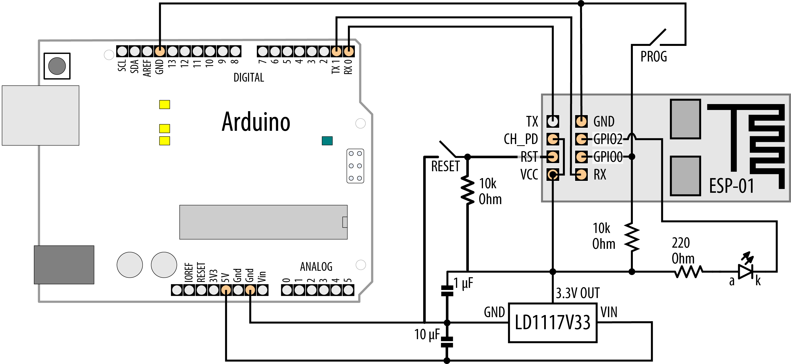
Using an Arduino as a USB to Serial adapter for the ESP8266
Discussion
This sketch includes the ESP8266 headers needed to connect to WiFi and construct a web server. It defines variables for your WiFi network’s SSID and password (which you will need to set before uploading the sketch) as well as an object for the web server. It also creates variables for the LED (LED_BUILTIN) that you’ll blink, the LED state, and a variable (formText) that holds an HTML fragment that displays a button. That variable is stored in flash memory rather than dynamic memory (see Recipe 17.3). With the ESP-01 board, connecting GPIO2 to GND at boot time prevents the board from booting properly, so we’re using inverted logic. Because the LED is tied to 3.3V, driving GPIO2 LOW will turn on the LED.
The example shown in the Solution is a bit more involved than the examples you saw for Ethernet or boards with built-in WiFi. That’s because the ESP8266WebServer is a bit more capable than the built-in Server class. In particular, it includes a number of features to make it easier to serve up web documents. Other boards can accomplish the same tasks, but they are much easier to develop thanks to the libraries that are included with the ESP8266 board package.
The following two functions are handlers. A handler’s job is to handle requests for a resource such as a web page. Every web server has a root document. When you go to http://oreilly.com, with or without a trailing /, you are making a request for the root (/) of the web site. The root handler, handleRoot, first checks for the presence of a parameter named toggle in the request. If so, it toggles the state of the LED (HIGH to LOW or vice-versa). Then, it displays the HTML fragment contained within formText.
The HTML fragment includes a form, which has an associated action (/, the web server root). When the form is submitted, it transmits any input elements as arguments to the handler. There is a hidden element named toggle, and a button that’s designed as the submission trigger (type="submit"). When you click the Submit button, it sends along toggle as an argument, which causes the LED to switch on or off.
The next handler’s job is to send a 404 error code for any other resource that you request from the server. After that comes setup, which initializes Serial, configures the led, initializes WiFi, and connects to your network. After that, it configures the two handlers, and starts the server.
Inside the loop, the sketch calls server.handleClient() to process any requests. If more than 10 seconds (MSG_DELAY) has passed, it prints the URL to the serial port. That way, you can open the Serial Monitor at any time to be reminded of the URL. Open this from a browser that’s on the same network as the ESP-01, and you can try out the button.
At the time of writing, there are over 16 different kinds of ESP8266 modules from the manufacturer of the chip, Espressif Systems. These vary by memory capacity, number of pins, and module size. A good overview of the modules can be found on the ESP8266 community wiki.
To enable these modules to be easily used in IoT projects, A number of suppliers to the maker community have created boards that add USB connectivity and other features that provide battery charging and simple programming when connected to the Arduino IDE. The easiest way to get started is to pick one with USB, such as Adafruit’s Feather HUZZAH (part number 2821) or the SparkFun ESP8266 Thing (WRL-13231). Both are relatively inexpensive, but not as cheap as a bare ESP8266 board like the ESP-01. The See Also section has links to step-by-step tutorials for getting started with both of these boards.
All of these have more than enough memory and computing power to support most projects. The ESP8266 has a 32-bit microprocessor core that runs at 80 MHz by default. It has 80K of RAM, and depending on which board you get, anywhere between 512K and 16MB of flash storage.
See Also
Sparkfun esp8266-thing tutorial https://learn.sparkfun.com/tutorials/esp8266-thing-hookup-guide/installing-the-esp8266-arduino-addon
Adafruit Feather Huzzah esp8266 tutorial https://learn.adafruit.com/adafruit-feather-huzzah-esp8266
Make Magazine article on connecting the ESP8266 http://makezine.com/2015/04/01/installing-building-arduino-sketch-5-microcontroller/
The ESP32 is a substantial upgrade to the ESP8266. It has more memory, runs faster, and can also support Bluetooth Low Energy. You can use it as a standalone microcontroller board, but you will also find it as a WiFi coprocessor in boards like the Arduino MKR WiFi 1010 and Arduino Uno WiFi Rev2 (#use_arduino_builtin_wifi).
15.6 Extracting Data from a Web Response
Problem
You want Arduino to get data from a web server. For example, you want to parse String, floating point, or integer data from a web server’s response.
Solution
This sketch uses the Open Notify (http://open-notify.org/Open-Notify-API/) web service to determine the position of the International Space Station. It parses out the time of the response as well as the ISS’ position in latitude and longitude, and prints the result to the Serial Monitor. This sketch has been designed to work with either the Ethernet library, the WiFININA library, or an ESP8266 board. You will need to uncomment the appropriate #include at the top of the sketch. This sketch consists of four files in all. The main sketch is shown first, followed by three header files. You’ll need to install the Time library before you compile this sketch (see Recipe 12.4).
/** Client-agnostic web data extraction sketch* A sketch that can work with ESP8266, WiFiNINA, and Ethernet boards*/// Uncomment only one of the following//#include "USE_NINA.h" // WiFiNINA boards//#include "USE_Ethernet.h" // Ethernet//#include "USE_ESP8266.h" // ESP8266 boards#include <TimeLib.h>charserver[]="api.open-notify.org";voidsetup(){Serial.begin(9600);if(!configureNetwork())// Start the network{Serial.println("Failed to configure the network");while(1){delay(0);// halt; ESP8266 does not like ∞ loop without a delay}}intret=client.connect(server,80);if(ret==1){Serial.println("Connected");client.println("GET /iss-now.json HTTP/1.0");// the HTTP requestclient.("Host: ");client.println(server);client.println("Connection: close");client.println();}else{Serial.println("Connection failed, error was: ");Serial.(ret,DEC);while(1){delay(0);// halt; ESP8266 does not like ∞ loop without a delay}}}chartimestampMarker[]=""timestamp":";charposMarker[]=""iss_position":";voidloop(){if(client.available()){if(client.find('"'))// Start of a string identifier{Stringid=client.readStringUntil('"');if(id.equals("timestamp"))// Start of timestamp{if(client.find(':'))// A ":" follows each identifier{unsignedlongtimestamp=client.parseInt();setTime(timestamp);// Set clock to the time of the responsedigitalClockDisplay();}else{Serial.println("Failed to parse timestamp.");}}if(id.equals("iss_position"))// Start of position data{if(client.find(':'))// A ":" follows each identifier{// Labels start with a " and position data ends with a }while(client.peek()!='}'&&client.find('"')){Stringid=client.readStringUntil('"');// Read the labelfloatval=client.parseFloat();// Read the valueclient.find('"');// Consume the trailing " after the floatSerial.(id+": ");Serial.println(val,4);}}else{Serial.println("Failed to parse position data.");}}}}if(!client.connected()){Serial.println();Serial.println("disconnecting.");client.stop();while(1){delay(0);// halt; ESP8266 does not like ∞ loop without a delay}}}StringpadDigits(intdigit){Stringstr=String("0")+digit;// Put a zero in front of the digitreturnstr.substring(str.length()-2);// Remove all but last two characters}voiddigitalClockDisplay(){Stringdatestr=String(year())+"-"+padDigits(month())+"-"+padDigits(day());Stringtimestr=String(hour())+":"+padDigits(minute())+":"+padDigits(second());Serial.println(datestr+" "+timestr);}
Here is the source code for the ESP8266 header file. While it doesn’t matter what you name the main sketch, you must create this by clicking the down-pointing arrow icon at the right of the Arduino IDE (just below the Serial Monitor icon), and choose New Tab. When Arduino prompts you for the new file name, you must name this USE_ESP8266.h. If you use this header, be sure to replace YOUR_SSID and YOUR_PASSWORD:
#include <SPI.h>
#include <ESP8266WiFi.h>
const char ssid[] = "YOUR_SSID";
const char password[] = "YOUR_PASSWORD";
WiFiClient client;
bool configureNetwork()
{
  WiFi.mode(WIFI_STA);
  WiFi.begin(ssid, password);
  while (WiFi.status() != WL_CONNECTED) // Wait for connection
  {
    delay(1000);
    Serial.print("Waiting for connection to "); Serial.println(ssid);
  }
  return true;
}
Here is the source code for the Ethernet header file.You must create this the same way you created the ESP8266 header file, but name this one USE_Ethernet.h. If you would prefer to use a hardcoded IP address, see Recipe 15.1 and modify this code accordingly.
#include <SPI.h>
#include <Ethernet.h>
byte mac[] = {0xDE, 0xAD, 0xBE, 0xEF, 0xFE, 0xED };
EthernetClient client;
bool configureNetwork()
{
  if (Ethernet.begin(mac))
  {
    delay(1000); // give the Ethernet module a second to initialize
    return true;
  }
  else
  {
    return false;
  }
}
Note
Unlike Recipe 15.2, this recipe doesn’t call Ethernet.maintain() to maintain the DHCP lease. Neither the WiFiNINA nor the ESP8266 require you to call maintain() periodically, but if you plan to create an Ethernet project that runs for a long time, you will need it. For an example of how you could add maintain() to a sketch, see Recipe 15.8.
Here is the source code for the WiFiNINA header file. You must create this the same way you created the ESP8266 header file, but name this one USE_NINA.h. If you use this header, be sure to replace YOUR_SSID and YOUR_PASSWORD:
#include <SPI.h>
#include <WiFiNINA.h>
const char ssid[] = "YOUR_SSID";
const char password[] = "YOUR_PASSWORD";
WiFiClient client;

bool configureNetwork()
{
  int status = WL_IDLE_STATUS; // WiFistatus

  if (WiFi.status() == WL_NO_MODULE)
  {
    Serial.println("Couldn't find WiFi hardware.");
    return false;
  }
  String fv = WiFi.firmwareVersion();
  if (fv < WIFI_FIRMWARE_LATEST_VERSION)
  {
    Serial.println("Please upgrade the WiFi firmware");
  }
  while (status != WL_CONNECTED)
  {
    Serial.print("Attempting WiFi connection to "); Serial.println(ssid);
    status = WiFi.begin(ssid, password); // Attempt connection until successful
    delay(1000); // Wait 1 second
  }
  return true;
}
Discussion
The ISS web service API from Open Notify returns results in the JSON (JavaScript Object Notation) format, which consists of attribute/value pairs of the form "attribute": value. The sketch makes a request to the web server using the same technique shown in Recipe 15.1 and Recipe 15.4.
The sketch searches the JSON response for values by using the Stream parsing functionality described in Recipe 4.5. In the loop, it looks for a double quote character ("), which signifies the start of a label such as “timestamp”. After the sketch finds the timestamp attribute label, it retrieves the first integer that follows, which is a number of seconds since the beginning of the Unix epoch. Conveniently, these are compatible with the functions from the Time library you saw in Recipe 12.4, so the sketch can use those functions to set the current time. It then prints the time using a digitalClockDisplay function similar to the one from that recipe.
If the sketch finds the “iss_position” identifier, it then looks for two more labels, which will be latitude and longitude, parses the float values associated with them, and displays each. When it either can’t find any more (there should only be those two), or it runs into a } character (the end of the “iss_position” identifier), it will finish. Here is sample output from the web service, with attribute values highlighted in bold:
{"message": "success", "timestamp": 1574635904, "iss_position":
{"latitude": "-37.7549", "longitude": "95.5304"}}
And here is the output that the sketch will display to the Serial Monitor:
Connected

2019-11-24 22:51:44
latitude: -37.7549
longitude: 95.5304

disconnecting.
15.7 Requesting Data from a Web Server Using XML
Problem
You want to retrieve data from a site that publishes information in XML format. For example, you want to use values from specific fields in weather providers offering XML API services.
Solution
This sketch retrieves the weather in London from the Open Weather. You must set up the three header files as described in Recipe 15.6 and uncomment one of the include lines to choose which kind of network connection to use. If you use WiFiNINA or ESP8266, you’ll need to change your SSID and password in the corresponding header file.
/** Simple Weather Client* gets xml data from http://openweathermap.org/* reads temperature from field: <temperature value="44.89"* writes temperature to analog output port.*/// Uncomment only one of the following//#include "USE_NINA.h" // WiFiNINA boards//#include "USE_Ethernet.h" // Ethernet//#include "USE_ESP8266.h" // ESP8266 boardscharserverName[]="api.openweathermap.org";Stringrequest="GET /data/2.5/weather?q=London,UK&units=imperial&mode=xml&APPID=";StringAPIkey="YOUR_KEY_HERE";// see textvoidsetup(){Serial.begin(9600);if(!configureNetwork())// Start the network{Serial.println("Failed to configure the network");while(1)delay(0);// halt; ESP8266 does not like ∞ loop without a delay}}voidloop(){if(client.connect(serverName,80)>0){Serial.println("Connected");// get weatherclient.println(request+APIkey+" HTTP/1.0");client.("Host: ");client.println(serverName);client.println("Connection: close");client.println();}else{Serial.println(" connection failed");}if(client.connected()){if(client.find("<temperature value=")){inttemperature=client.parseInt();Serial.("Temperature: ");Serial.println(temperature);}elseSerial.("Could not find temperature field");if(client.find("<humidity value=")){inthumidity=client.parseInt();Serial.("Humidity: ");Serial.println(humidity);}elseSerial.("Could not find humidity field");}else{Serial.println("Disconnected");}client.stop();client.flush();delay(60000);// wait a minute before next update}
Discussion
Open Weather provides weather data for over 200,000 cities worldwide. It is a free service for casual use but you will need to register to get an API key. See https://openweathermap.org/appid for information on how get a key and terms of use.
The sketch connects to api.openweathermap.org and then sends the page request http://api.openweathermap.org/data/2.5/weather?q=London,UK&units=imperial&mode=xml&APPID=YOUR_KEY_HERE.
The string following q= specifies the city and country (see http://openweathermap.org/help/city_list.txt for a complete list of cities). The units=imperial will return temperature in Fahrenheit, and mode=xml causes the API to return results in XML format. You will need to change this line of code to put your Open Weather Map API key in: String APIkey = "YOUR_KEY_HERE";.
The XML data returned looks like this:
<current>
  <city id="2643743" name="London">
    <coord lon="-0.13" lat="51.51"/>
    <country>GB</country>
    <timezone>0</timezone>
    <sun rise="2019-11-25T07:34:34" set="2019-11-25T16:00:36"/>
  </city>
  <temperature value="48" min="45" max="51.01" unit="fahrenheit"/>
  <humidity value="93" unit="%"/>
  <pressure value="1004" unit="hPa"/>
  <wind>
    <speed value="6.93" unit="mph" name="Light breeze"/>
    <gusts/>
    <direction value="100" code="E" name="East"/>
  </wind>
  <clouds value="75" name="broken clouds"/>
  <visibility value="10000"/>
  <precipitation mode="no"/>
  <weather number="803" value="broken clouds" icon="04n"/>
  <lastupdate value="2019-11-25T02:02:46"/>
</current>
The sketch parses the data by using client.find() to locate the temperature and humidity tags, and then uses client.parseInt() to retrieve the values for each of those. The sketch will retrieve the weather data every 60 seconds. This is a relatively small XML message. If you are processing a very large XML message, you could end up using to much of Arduino’s resources (CPU and RAM). JSON can often be a more compact notation (see Recipe 15.6).
15.8 Setting Up an Arduino to Be a Web Server
Problem
You want Arduino to serve web pages. For example, you want to use your web browser to view the values of sensors connected to Arduino analog pins.
Solution
This is based on the standard Arduino Web Server Ethernet example sketch distributed with Arduino that shows the value of the analog input pins. It has been modified to be adaptable to boards with WiFiNINA modules (Recipe 15.4) as well as the ESP8266 (Recipe 15.5). You will need to uncomment the appropriate #include at the top of the sketch. This sketch consists of four files in all. The main sketch is shown first, followed by three header files:
/** Web Server sketch*/// Uncomment only one of the following//#include "USE_NINA.h" // WiFiNINA boards//#include "USE_Ethernet.h" // Ethernet//#include "USE_ESP8266.h" // ESP8266 boardsvoidsetup(){Serial.begin(9600);if(!configureNetwork())// Start the network{Serial.println("Failed to configure the network");while(1)delay(0);// halt; ESP8266 does not like ∞ loop without a delay}server.begin();}#define MSG_DELAY 10000voidloop(){staticunsignedlongnextMsgTime=0;if(millis()>nextMsgTime){Serial.("Visit me at http://");Serial.println(getIP());nextMsgTime=millis()+MSG_DELAY;}maintain();// Maintain the DHCP lease manually if neededclient=server.available();// Listen for connectionsif(client){Serial.println("New client connection");// an http request ends with a blank linebooleancurrentLineIsBlank=true;while(client.connected()){if(client.available()){charc=client.read();Serial.write(c);// If you've reached the end of a blank line and found another ,// then you've reached the end of the headers.if(c==' '&¤tLineIsBlank){// Send a standard http response headerclient.println("HTTP/1.1 200 OK");client.println("Content-Type: text/html");client.println("Connection: close");// Close connection at end of responseclient.println("Refresh: 5");// refresh the page automatically every 5 secclient.println();// End of headersclient.println("<!DOCTYPE HTML>");client.println("<HTML>");// Display the value of each analog input pinfor(intanalogChannel=0;analogChannel<6;analogChannel++){intsensorReading=analogRead(analogChannel);client.("A");client.(analogChannel);client.(" = ");client.(sensorReading);client.println("<BR />");}client.println("</HTML>");break;// Break out of the while loop}if(c==' '){// you're starting a new linecurrentLineIsBlank=true;}elseif(c!=' '){// you've gotten a character on the current linecurrentLineIsBlank=false;}}}// Give the web browser time to receive the datadelay(100);// close the connection:client.stop();Serial.println("Client disonnected");}}
Here is the source code for the Ethernet header file.You must create this the same way you created the ESP8266 header file, but name this one USE_Ethernet.h. Because this sketch is a long-running server, the maintain() function is included, which is called from within the sketch’s loop function. This will keep the DHCP lease active (see Recipe 15.2). If you would prefer to use a hardcoded IP address, see Recipe 15.1 and modify this code accordingly.
#include <SPI.h>
#include <Ethernet.h>
byte mac[] = {0xDE, 0xAD, 0xBE, 0xEF, 0xFE, 0xED };
EthernetClient client;
EthernetServer server(80);

bool configureNetwork()
{
  if (Ethernet.begin(mac))
  {
    delay(1000); // give the Ethernet module a second to initialize
    return true;
  }
  else
  {
    return false;
  }
}

IPAddress getIP()
{
  return Ethernet.localIP();
}

#define MAINTAIN_DELAY 750 // Maintain DHCP lease every .75 seconds
void maintain()
{
  static unsigned long nextMaintain = millis() + MAINTAIN_DELAY;
  if (millis() > nextMaintain)
  {
    nextMaintain = millis() + MAINTAIN_DELAY;
    int ret = Ethernet.maintain();
    if (ret == 1 || ret == 3)
    {
      Serial.print("Failed to maintain DHCP lease. Error: ");
      Serial.println(ret);
    }
  }
}
Here is the source code for the ESP8266 header file. While it doesn’t matter what you name the main sketch, you must create this by clicking the down-pointing arrow icon at the right of the Arduino IDE (just below the Serial Monitor icon), and choose New Tab. When Arduino prompts you for the new file name, you must name this USE_ESP8266.h. If you use this header, be sure to replace YOUR_SSID and YOUR_PASSWORD. The maintain function is empty because you do not need to manually keep the lease active with the ESP8266 (or WiFiNINA):
#include <SPI.h>
#include <ESP8266WiFi.h>
const char ssid[] = "YOUR_SSID";
const char password[] = "YOUR_PASSWORD";
WiFiClient client;
WiFiServer server(80);

bool configureNetwork()
{
  WiFi.mode(WIFI_STA);
  WiFi.begin(ssid, password);
  while (WiFi.status() != WL_CONNECTED) // Wait for connection
  {
    delay(1000);
    Serial.print("Waiting for connection to "); Serial.println(ssid);
  }
  return true;
}

IPAddress getIP()
{
  return WiFi.localIP();
}

void maintain()
{
  // Do nothing
}
Here is the source code for the WiFiNINA header file. You must create this the same way you created the ESP8266 header file, but name this one USE_NINA.h. If you use this header, be sure to replace YOUR_SSID and YOUR_PASSWORD:
#include <SPI.h>
#include <WiFiNINA.h>
const char ssid[] = "YOUR_SSID";
const char password[] = "YOUR_PASSWORD";
WiFiClient client;
WiFiServer server(80);

bool configureNetwork()
{
  int status = WL_IDLE_STATUS; // WiFistatus

  if (WiFi.status() == WL_NO_MODULE)
  {
    Serial.println("Couldn't find WiFi hardware.");
    return false;
  }
  String fv = WiFi.firmwareVersion();
  if (fv < WIFI_FIRMWARE_LATEST_VERSION)
  {
    Serial.println("Please upgrade the WiFi firmware");
  }
  while (status != WL_CONNECTED)
  {
    Serial.print("Attempting WiFi connection to "); Serial.println(ssid);
    status = WiFi.begin(ssid, password); // Attempt connection until successful
    delay(1000); // Wait 1 second
  }
  return true;
}

IPAddress getIP()
{
  return WiFi.localIP();
}

void maintain()
{
  // Do nothing
}
Discussion
Similar to Recipe 15.6, this sketch uses one of three header files to determine how to connect to the network: if you include the USE_Ethernet.h, header, this sketch will connect to Ethernet using DHCP. Because DHCP with Ethernet requires you to manually maintain the DHCP lease, there’s a maintain function that you must call from within loop. This code wasn’t included in Recipe 15.6 because that sketch would run once and stop. If you use an ESP8266 board, you’ll need to include the USE_ESP8266.h header file, and if you use a WiFiNINA board, you’ll need to include USE_NINA.h. Each header file also defines a client and server variable, and exposes methods to configure the network (configureNetwork) and to get the assigned IP address (getIP).
The sketch begins by starting the serial port, and then it configures the network using the hardware-specific function, and starts the server. Within the loop, it displays a message every 10 seconds showing the URL you need to connect to the server. When you open this URL in a web browser, you should see a page showing the values on analog input pins 0 through 6 (see Chapter 5 for more on the analog ports).
The two lines in setup initialize the Ethernet library and configure your web server to the IP address you provide. The loop waits for and then processes each request received by the web server:
client = server.available();
The client object here represents the client connected to the web server. Depending on which header you included, this will either be an EthernetClient or WiFiClient object.
if (client) tests that the client has been successfully connected.
while (client.connected()) tests if the web server is connected to a client making a request.
client.available() and client.read() check if data is available from the client, and read a byte if it is. This is similar to Serial.available(), discussed in Chapter 4, except the data is coming from the Internet rather than the serial port. The code reads data until it finds the first line with no data, signifying the end of a request. An HTTP header is sent using the client.println commands followed by the printing of the values of the analog ports.
Note
The ESP8266 board package includes a rich set of libraries for creating web servers. Unless you are writing code that should support a variety of networking hardware, you may want to use those features. See Recipe 15.5 for more details.
15.9 Handling Incoming Web Requests
Problem
You want to control digital and analog outputs with Arduino acting as a web server. For example, you want to control the values of specific pins through parameters sent from your web browser.
Solution
This sketch reads requests sent from a browser and changes the values of digital and analog output ports as requested. You will need to open the Serial Monitor to see what URL to use to connect to the sketch.
The URL (text received from a browser request) contains one or more fields starting with the word pin followed by a D for digital or A for analog and the pin number. The value for the pin follows an equals sign.
For example, sending http://IP_ADDRESS/?pinD2=1 from your browser’s address bar turns digital pin 2 on; http://IP_ADDRESS/?pinD2=0 turns pin 2 off. (See Chapter 7 if you need information on connecting LEDs to Arduino pins.) You would need to replace IP_ADDRESS with the IP address shown in the Serial Monitor.
Note
You must set up the three header files as described in Recipe 15.8 and uncomment one of the include lines to choose which kind of network connection to use. If you use WiFiNINA or ESP8266, you’ll need to change your SSID and password in the corresponding header file. The ESP8266 has a limited number of pins available for output, so you will need to consult the documentation for your ESP8266 board to find a pin that can be used. Writing to some pins may cause the board to behave erratically.
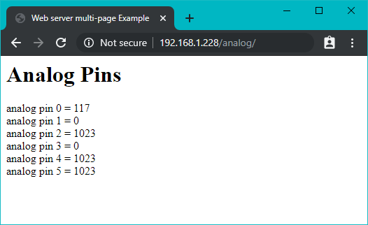
Figure 15-2 shows what you will see on your web browser when connected to the web server code that follows.

Browser page displaying output created by this recipe’s Solution
/** Incoming request sketch* Respond to requests in the URL to change digital and analog output ports* show the number of ports changed and the value of the analog input pins.* for example:* sending http://IP_ADDRESS/?pinD2=1 turns digital pin 2 on* sending http://IP_ADDRESS/?pinD2=0 turns pin 2 off.* This sketch demonstrates text parsing using Arduino Stream class.*/// Uncomment only one of the following//#include "USE_NINA.h" // WiFiNINA boards//#include "USE_Ethernet.h" // Ethernet//#include "USE_ESP8266.h" // ESP8266 boardsvoidsetup(){Serial.begin(9600);if(!configureNetwork())// Start the network{Serial.println("Failed to configure the network");while(1)delay(0);// halt; ESP8266 does not like ∞ loop without a delay}server.begin();}#define MSG_DELAY 10000voidloop(){staticunsignedlongnextMsgTime=0;if(millis()>nextMsgTime){Serial.("Try http://");Serial.(getIP());Serial.println("?pinD2=1");nextMsgTime=millis()+MSG_DELAY;}maintain();// Maintain the DHCP lease manually if neededclient=server.available();if(client){while(client.connected()){if(client.available()){// counters to show the number of pin change requestsintdigitalRequests=0;intanalogRequests=0;if(client.find("GET /"))// search for 'GET'{// find tokens starting with "pin" and stop at the end of the linewhile(client.findUntil("pin","")){chartype=client.read();// D or A// the next ascii integer value in the stream is the pinintpin=client.parseInt();intval=client.parseInt();// the integer after that is the valueif(type=='D'){Serial.("Digital pin ");pinMode(pin,OUTPUT);digitalWrite(pin,val);digitalRequests++;}elseif(type=='A'){Serial.("Analog pin ");analogWrite(pin,val);analogRequests++;}else{Serial.("Unexpected type ");Serial.(type);}Serial.(pin);Serial.("=");Serial.println(val);}}Serial.println();// the findUntil has detected the blank line (a lf followed by cr)// so the http request has ended and we can send a reply// send a standard http response headerclient.println("HTTP/1.1 200 OK");client.println("Content-Type: text/html");client.println();// output the number of pins handled by the requestclient.(digitalRequests);client.(" digital pin(s) written");client.println("<br />");client.(analogRequests);client.(" analog pin(s) written");client.println("<br />");client.println("<br />");// output the value of each analog input pinfor(inti=0;i<6;i++){client.("analog input ");client.(i);client.(" is ");client.(analogRead(i));client.println("<br />");}break;// Exit the while() loop}}// give the web browser time to receive the datadelay(100);client.stop();}}
Discussion
If you were to send this command (replacing IP_ADDRESS with the IP address displayed in the Serial Monitor) http://IP_ADDRESS/?pinD2=1, the sketch would take pin 2 high. Here is how the instructions in the URL are broken down: Everything before the question mark is treated as the address of the web server (for example, 192.168.1.177). The remaining data is a list of fields, each beginning with the word pin followed by a D indicating a digital pin or A indicating an analog pin. The numeric value following the D or A is the pin number. This is followed by an equals sign and finally the value you want to set the pin to. pinD2=1 sets digital pin 2 HIGH. There is one field per pin, and subsequent fields are separated by an ampersand. You can have as many fields as there are Arduino pins you want to change.
The request can be extended to handle multiple parameters by using ampersands to separate multiple fields. For example:
- http://IP_ADDRESS/?pinD2=1&pinD3=0&pinA9=128&pinA11=255
Each field within the ampersand is handled as described earlier. You can have as many fields as there are Arduino pins you want to change.
15.10 Handling Incoming Requests for Specific Pages
Problem
You want to have more than one page on your web server; for example, to show the status of different sensors on different pages.
Solution
This sketch looks for requests for pages named “analog” or “digital” and displays the pin values accordingly.
Note
You must set up the three header files as described in Recipe 15.8 and uncomment one of the include lines to choose which kind of network connection to use. If you use WiFiNINA or ESP8266, you’ll need to change your SSID and password in the corresponding header file.
/** WebServerMultiPage sketch* Respond to requests in the URL to view digital and analog output ports* http://IP_ADDRESS/analog/ displays analog pin data* http://IP_ADDRESS/digital/ displays digital pin data*/// Uncomment only one of the following//#include "USE_NINA.h" // WiFiNINA boards//#include "USE_Ethernet.h" // Ethernet//#include "USE_ESP8266.h" // ESP8266 boardsconstintMAX_PAGE_NAME_LEN=8;// max characters in a page namecharbuffer[MAX_PAGE_NAME_LEN+1];// page name + terminating nullvoidsetup(){Serial.begin(9600);if(!configureNetwork())// Start the network{Serial.println("Failed to configure the network");while(1)delay(0);// halt; ESP8266 does not like ∞ loop without a delay}server.begin();}#define MSG_DELAY 10000voidloop(){staticunsignedlongnextMsgTime=0;if(millis()>nextMsgTime){Serial.("Try http://");Serial.(getIP());Serial.println("/analog/");nextMsgTime=millis()+MSG_DELAY;}maintain();// Maintain the DHCP lease manually if neededclient=server.available();if(client){while(client.connected()){if(client.available()){if(client.find("GET ")){// look for the page namememset(buffer,0,sizeof(buffer));// clear the bufferif(client.find("/"))if(client.readBytesUntil('/',buffer,MAX_PAGE_NAME_LEN)){if(strcmp(buffer,"analog")==0)showAnalog();elseif(strcmp(buffer,"digital")==0)showDigital();elseunknownPage(buffer);}}Serial.println();break;// Exit the while() loop}}// give the web browser time to receive the datadelay(100);client.stop();}}voidshowAnalog(){Serial.println("analog");sendHeader();client.println("<h1>Analog Pins</h1>");// output the value of each analog input pinfor(inti=0;i<6;i++){client.("analog pin ");client.(i);client.(" = ");client.(analogRead(i));client.println("<br />");}}voidshowDigital(){Serial.println("digital");sendHeader();client.println("<h1>Digital Pins</h1>");// show the value of each digital pinfor(inti=2;i<8;i++){pinMode(i,INPUT_PULLUP);client.("digital pin ");client.(i);client.(" is ");if(digitalRead(i)==LOW)client.("HIGH");elseclient.("LOW");client.println("<br />");}client.println("</body></html>");}voidunknownPage(char*page){sendHeader();client.println("<h1>Unknown Page</h1>");client.(page);client.println("<br />");client.println("Recognized pages are:<br />");client.println("/analog/<br />");client.println("/digital/<br />");client.println("</body></html>");}voidsendHeader(){// send a standard http response headerclient.println("HTTP/1.1 200 OK");client.println("Content-Type: text/html");client.println();client.println("<html><head><title>Web server multi-page Example</title>");client.println("<body>");}
Discussion
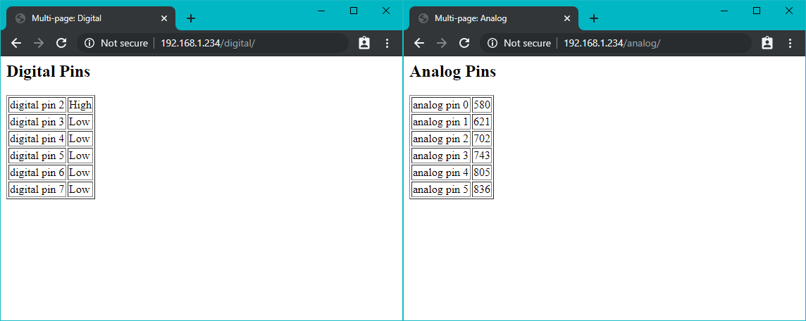
You can test this from your web browser by typing http://IP_ADDRESS/analog/ or http://IP_ADDRESS/digital/ (replace IP_ADDRESS with the IP address displayed in the Serial Monitor).
Figure 15-3 shows the expected output. To test it, you could wire one or more buttons to the digital pins and one or more potentiometers to the analog pins. Because the sketch uses the built-in pullup resistors (see Recipe 2.4), the logic is inverted (LOW means a button is pressed and HIGH means it is not). See Recipe 5.6 for instructions on working with potentiometers.
Browser output showing analog pin values
The sketch looks for the / character to determine the end of the page name. The server will report an unknown page if the / character does not terminate the page name.
You can easily enhance this with some code from Recipe 15.9 to allow control of Arduino pins from another page named update. Here is the section of loop that you need to change (added lines shown in emphasized text):
if(client.readBytesUntil('/',buffer,MAX_PAGE_NAME_LEN)){if(strcmp(buffer,"analog")==0)showAnalog();elseif(strcmp(buffer,"digital")==0)showDigital();// add this code for new page named: updateelseif(strcmp(buffer,"update")==0)doUpdate();elseunknownPage(buffer);}
Here is the doUpdate function. The ESP8266 has a limited number of pins available for output, so you will need to consult the documentation for your ESP8266 board to find a pin that can be used. Writing to some pins may cause the board to behave erratically.
voiddoUpdate(){Serial.println("update");sendHeader();// find tokens starting with "pin" and stop on the first blank linewhile(client.findUntil("pin","")){chartype=client.read();// D or Aintpin=client.parseInt();intval=client.parseInt();if(type=='D'){client.("Digital pin ");pinMode(pin,OUTPUT);digitalWrite(pin,val);}elseif(type=='A'){client.("Analog pin ");analogWrite(pin,val);}else{client.("Unexpected type ");Serial.(type);}client.(pin);client.("=");client.println(val);}client.println("</body></html>");}
Sending http://IP_ADDRESS/update/?pinA5=128 from your browser’s address bar writes the value 128 to analog output pin 5.
Note
The ESP8266 board package includes a rich set of libraries for creating web servers. Unless you are writing code that should support a variety of networking hardware, you may want to use those features. See Recipe 15.5 for more details.
15.11 Using HTML to Format Web Server Responses
Problem
You want to use HTML elements such as tables and images to improve the look of web pages served by Arduino. For example, you want the output from Recipe 15.10 to be rendered in an HTML table.
Solution
Figure 15-4 shows how the web server in this recipe’s Solution formats the browser page to display pin values. (You can compare this to the unformatted values shown in Figure 15-3.)
Browser pages using HTML formatting
This sketch shows the functionality from Recipe 15.10 with output formatted using HTML.
Note
You must set up the three header files as described in Recipe 15.8 and uncomment one of the include lines to choose which kind of network connection to use. If you use WiFiNINA or ESP8266, you’ll need to change your SSID and password in the corresponding header file. The ESP8266 has a limited number of pins available for output, so you will need to consult the documentation for your ESP8266 board to find a pin that can be used. Writing to some pins may cause the board to behave erratically.
/** WebServerMultiPageHTML sketch* Display analog and digital pin values using HTML formatting*/// Uncomment only one of the following//#include "USE_NINA.h" // WiFiNINA boards//#include "USE_Ethernet.h" // Ethernet//#include "USE_ESP8266.h" // ESP8266 boardsconstintMAX_PAGE_NAME_LEN=8;// max characters in a page namecharbuffer[MAX_PAGE_NAME_LEN+1];// page name + terminating nullvoidsetup(){Serial.begin(9600);if(!configureNetwork())// Start the network{Serial.println("Failed to configure the network");while(1)delay(0);// halt; ESP8266 does not like ∞ loop without a delay}server.begin();pinMode(LED_BUILTIN,OUTPUT);for(inti=0;i<3;i++){digitalWrite(LED_BUILTIN,HIGH);delay(500);digitalWrite(LED_BUILTIN,LOW);delay(500);}}#define MSG_DELAY 10000voidloop(){staticunsignedlongnextMsgTime=0;if(millis()>nextMsgTime){Serial.("Try http://");Serial.(getIP());Serial.println("/analog/");nextMsgTime=millis()+MSG_DELAY;}maintain();// Maintain the DHCP lease manually if neededclient=server.available();if(client){while(client.connected()){if(client.available()){if(client.find("GET ")){// look for the page namememset(buffer,0,sizeof(buffer));// clear the bufferif(client.find("/"))if(client.readBytesUntil('/',buffer,MAX_PAGE_NAME_LEN)){if(strcasecmp(buffer,"analog")==0)showAnalog();elseif(strcasecmp(buffer,"digital")==0)showDigital();elseunknownPage(buffer);}}break;}}// give the web browser time to receive the datadelay(100);client.stop();}}voidshowAnalog(){sendHeader("Multi-page: Analog");client.println("<h2>Analog Pins</h2>");client.println("<table border='1' >");for(inti=0;i<6;i++){// output the value of each analog input pinclient.("<tr><td>analog pin ");client.(i);client.(" </td><td>");client.(analogRead(i));client.println("</td></tr>");}client.println("</table>");client.println("</body></html>");}voidshowDigital(){sendHeader("Multi-page: Digital");client.println("<h2>Digital Pins</h2>");client.println("<table border='1'>");for(inti=2;i<8;i++){// show the value of digital pinspinMode(i,INPUT_PULLUP);digitalWrite(i,HIGH);// turn on pull-upsclient.("<tr><td>digital pin ");client.(i);client.(" </td><td>");if(digitalRead(i)==LOW)client.("High");elseclient.("Low");client.println("</td></tr>");}client.println("</table>");client.println("</body></html>");}voidunknownPage(char*page){sendHeader("Unknown Page");client.println("<h1>Unknown Page</h1>");client.(page);client.println("<br />");client.println("Recognized pages are:<br />");client.println("/analog/<br />");client.println("/digital/<br />");client.println("</body></html>");}voidsendHeader(char*title){// send a standard http response headerclient.println("HTTP/1.1 200 OK");client.println("Content-Type: text/html");client.println();client.("<html><head><title>");client.println(title);client.println("</title><body>");}
Discussion
The same information is provided as in Recipe 15.10, but here the data is formatted using an HTML table. The following code indicates that the web browser should create a table with a border width of 1:
client.println("<table border='1' >");
The for loop defines the table data cells with the <td> tag and the row entries with the <tr> tag. The following code places the string "analog pin" in a cell starting on a new row:
client.("<tr><td>analog pin ");
This is followed by the value of the variable i:
client.(i);
The next line contains the tag that closes the cell and begins a new cell:
client.(" </td><td>");
This writes the value returned from analogRead into the cell:
client.print(analogRead(i));
The tags to end the cell and end the row are written as follows:
client.println("</td></tr>");
The for loop repeats this until all six analog values are written.
See Also
Learning Web Design by Jennifer Robbins (O’Reilly)
Web Design in a Nutshell by Jennifer Niederst Robbins (O’Reilly)
HTML & XHTML: The Definitive Guide by Chuck Musciano and Bill Kennedy (O’Reilly)
15.12 Requesting Web Data Using Forms (POST)
Problem
You want to create web pages with forms that allow users to select an action to be performed by Arduino. Figure 15-5 shows the web page created by this recipe’s Solution.

Web form with buttons
Solution
This sketch creates a web page that has a form with buttons. Users navigating to this page will see the buttons in the web browser and the Arduino web server will respond to the button clicks. In this example, the sketch turns a pin on and off depending on which button is pressed.
Note
You must set up the three header files as described in Recipe 15.8 and uncomment one of the include lines to choose which kind of network connection to use. If you use WiFiNINA or ESP8266, you’ll need to change your SSID and password in the corresponding header file. The ESP8266 has a limited number of pins available for output, so you will need to consult the documentation for your ESP8266 board to find a pin that can be used. Writing to some pins may cause the board to behave erratically.
/** WebServerPost sketch* Turns a pin on and off using HTML form*/// Uncomment only one of the following//#include "USE_NINA.h" // WiFiNINA boards//#include "USE_Ethernet.h" // Ethernet//#include "USE_ESP8266.h" // ESP8266 boardsconstintMAX_PAGE_NAME_LEN=8;// max characters in a page namecharbuffer[MAX_PAGE_NAME_LEN+1];// page name + terminating nullvoidsetup(){Serial.begin(9600);if(!configureNetwork())// Start the network{Serial.println("Failed to configure the network");while(1)delay(0);// halt; ESP8266 does not like ∞ loop without a delay}server.begin();}#define MSG_DELAY 10000voidloop(){staticunsignedlongnextMsgTime=0;if(millis()>nextMsgTime){Serial.("Try http://");Serial.println(getIP());nextMsgTime=millis()+MSG_DELAY;}maintain();// Maintain the DHCP lease manually if neededclient=server.available();if(client){inttype=0;while(client.connected()){if(client.available()){// GET, POST, or HEADmemset(buffer,0,sizeof(buffer));// clear the bufferif(client.readBytesUntil('/',buffer,sizeof(buffer))){Serial.println(buffer);if(strcmp(buffer,"POST ")==0){client.find("");// skip to the body// find string starting with "pin", stop on first end of line// the POST parameters expected in the form pinDx=Y// where x is the pin number and Y is 0 for LOW and 1 for HIGHwhile(client.findUntil("pinD","")){intpin=client.parseInt();// the pin numberintval=client.parseInt();// 0 or 1pinMode(pin,OUTPUT);digitalWrite(pin,val);}}else// probably a GET{if(client.find("favicon.ico"))// Send 404 for faviconssendHeader("404 Not Found","Not found");}sendHeader("200 OK","Post example");//create HTML button to turn off pin 8client.println("<h2>Click buttons to turn pin 8 on or off</h2>");client.("<form action='/' method='POST'><p><input type='hidden' name='pinD8'");client.println(" value='0'><input type='submit' value='Off'/></form>");//create HTML button to turn on pin 8client.("<form action='/' method='POST'><p><input type='hidden' name='pinD8'");client.(" value='1'><input type='submit' value='On'/></form>");client.println("</body></html>");client.stop();}break;// exit the while loop}}// give the web browser time to receive the datadelay(100);client.stop();}}voidsendHeader(char*code,char*title){// send a standard http response headerclient.("HTTP/1.1 ");client.println(code);client.println("Content-Type: text/html");client.println();client.("<html><head><title>");client.(title);client.println("</title><body>");}
Discussion
A web page with a user interface form consists of HTML tags that identify the controls (buttons, checkboxes, labels, etc.) that comprise the user interface. This recipe uses buttons for user interaction.
These lines create a form with a button named pinD8 that is labeled “OFF,” which will send back a value of 0 (zero) when clicked:
client.print("<form action='/' method='POST'><p><input type='hidden' name='pinD8'");
client.println(" value='0'><input type='submit' value='Off'/></form>");
When the server receives a request from a browser, it looks for the "POST " string to identify the start of the posted form:
if(strcmp(buffer,"POST ")==0)// find the start of the posted formclient.find("");// skip to the body// find parameters starting with "pin" and stop on the first blank line// the POST parameters expected in the form pinDx=Y// where x is the pin number and Y is 0 for LOW and 1 for HIGH
If the OFF button was pressed, the received page will contain the string pinD8=0, or pinD8=1 for the ON button.
The sketch searches until it finds the button name (pinD):
while(client.findUntil("pinD",""))
The findUntil method in the preceding code will search for “pinD” and stop searching at the end of a line (
is the newline carriage return sent by the web browser at the end of a form).
The number following the name pinD is the pin number:
int pin = client.parseInt(); // the pin number
And the value following the pin number will be 0 if button OFF was pressed or 1 if button ON was pressed:
int val = client.parseInt(); // 0 or 1
The value received is written to the pin after setting the pin mode to output:
pinMode(pin,OUTPUT);digitalWrite(pin,val);
More buttons can be added by inserting tags for the additional controls. The following lines add another button to turn on digital pin 9:
//create HTML button to turn on pin 9client.("<form action='/' method='POST'><p><input type='hidden' name='pinD9'");client.(" value='1'><input type='submit' value='On'/></form>");
15.13 Serving Web Pages Containing Large Amounts of Data
Problem
Your web pages require more memory than you have available, so you want to use program memory (also known as progmem or flash memory) to store data (see Recipe 17.4).
Solution
This sketch combines the POST code from Recipe 15.12 with the HTML code from Recipe 15.11 and adds new code to access text stored in progmem. As in Recipe 15.11, the server can display analog and digital pin status and turn digital pins on and off (see Figure 15-6).
Note
You must set up the three header files as described in Recipe 15.8 and uncomment one of the include lines to choose which kind of network connection to use. If you use WiFiNINA or ESP8266, you’ll need to change your SSID and password in the corresponding header file. The ESP8266 has a limited number of pins available for output, so you will need to consult the documentation for your ESP8266 board to find a pin that can be used. Writing to some pins may cause the board to behave erratically.
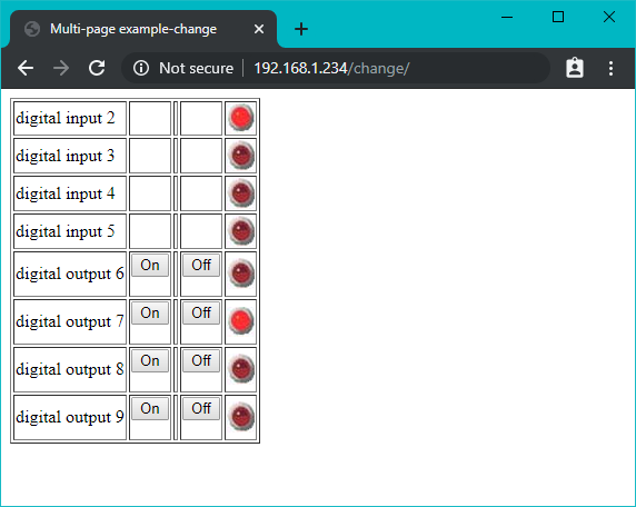
Web page with LED images
/** WebServerMultiPageHTMLProgmem sketch** Respond to requests in the URL to change digital and analog output ports* show the number of ports changed and the value of the analog input pins.** http://192.168.1.177/analog/ displays analog pin data* http://192.168.1.177/digital/ displays digital pin data* http://192.168.1.177/change/ allows changing digital pin data**/// Uncomment only one of the following//#include "USE_NINA.h" // WiFiNINA boards//#include "USE_Ethernet.h" // Ethernet//#include "USE_ESP8266.h" // ESP8266 boards#include <avr/pgmspace.h>// for progmem#define P(name) static const char name[] PROGMEM// declare a static stringconstintMAX_PAGENAME_LEN=8;// max characters in page namecharbuffer[MAX_PAGENAME_LEN+1];// additional character for terminating nullvoidsetup(){Serial.begin(9600);if(!configureNetwork())// Start the network{Serial.println("Failed to configure the network");while(1)delay(0);// halt; ESP8266 does not like ∞ loop without a delay}server.begin();Serial.println(F("Ready"));}#define MSG_DELAY 10000voidloop(){staticunsignedlongnextMsgTime=0;if(millis()>nextMsgTime){Serial.("Try http://");Serial.(getIP());Serial.println("/change/");nextMsgTime=millis()+MSG_DELAY;}maintain();// Maintain the DHCP lease manually if neededclient=server.available();if(client){inttype=0;while(client.connected()){if(client.available()){// GET, POST, or HEADmemset(buffer,0,sizeof(buffer));// clear the bufferif(client.readBytesUntil('/',buffer,MAX_PAGENAME_LEN)){if(strcmp(buffer,"GET ")==0)type=1;elseif(strcmp(buffer,"POST ")==0)type=2;// look for the page namememset(buffer,0,sizeof(buffer));// clear the bufferif(client.readBytesUntil('/',buffer,MAX_PAGENAME_LEN)){if(strcasecmp(buffer,"analog")==0)showAnalog();elseif(strcasecmp(buffer,"digital")==0)showDigital();elseif(strcmp(buffer,"change")==0)showChange(type==2);elseunknownPage(buffer);}}break;}}// give the web browser time to receive the datadelay(100);client.stop();}}voidshowAnalog(){Serial.println(F("analog"));sendHeader("Multi-page example-Analog");client.println("<h1>Analog Pins</h1>");// output the value of each analog input pinclient.println(F("<table border='1' >"));for(inti=0;i<6;i++){client.(F("<tr><td>analog pin "));client.(i);client.(F(" </td><td>"));client.(analogRead(i));client.println(F("</td></tr>"));}client.println(F("</table>"));client.println(F("</body></html>"));}// mime encoded data for the led on and off images:// see: http://www.motobit.com/util/base64-decoder-encoder.aspP(led_on)="<img src="data:image/jpg;base64,""/9j/4AAQSkZJRgABAgAAZABkAAD/7AARRHVja3kAAQAEAAAAHgAA/+4ADkFkb2JlAGTAAAAAAf/b""AIQAEAsLCwwLEAwMEBcPDQ8XGxQQEBQbHxcXFxcXHx4XGhoaGhceHiMlJyUjHi8vMzMvL0BAQEBA""QEBAQEBAQEBAQAERDw8RExEVEhIVFBEUERQaFBYWFBomGhocGhomMCMeHh4eIzArLicnJy4rNTUw""MDU1QEA/QEBAQEBAQEBAQEBA/8AAEQgAGwAZAwEiAAIRAQMRAf/EAIIAAAICAwAAAAAAAAAAAAAA""AAUGAAcCAwQBAAMBAAAAAAAAAAAAAAAAAAACBAUQAAECBAQBCgcAAAAAAAAAAAECAwARMRIhQQQF""UWFxkaHRMoITUwYiQnKSIxQ1EQAAAwYEBwAAAAAAAAAAAAAAARECEgMTBBQhQWEiMVGBMkJiJP/a""AAwDAQACEQMRAD8AcNz3BGibKie0nhC0v3A+teKJt8JmZEdHuZalOitgUoHnEpQEWtSyLqgACWFI""nixWiaQhsUFFBiQSbiMvvrmeCBp27eLnG7lFTDxs+Kra8oOyium3ltJUAcDIy4EUMN/7Dnq9cPMO""W90E9kxeyF2d3HFOQ175olKudUm7TqlfKqDQEDOFR1sNqtC7k5ERYjndNPFSArtvnI/nV+ed9coI""ktd2BgozrSZO3J5jVEXRcwD2bbXNdq0zT+BohTyjgPp5SYdPJZ9NP2jsiIz7vhjLohtjnqJ/ouPK""co//2Q=="""/>";P(led_off)="<img src="data:image/jpg;base64,""/9j/4AAQSkZJRgABAgAAZABkAAD/7AARRHVja3kAAQAEAAAAHgAA/+4ADkFkb2JlAGTAAAAAAf/b""AIQAEAsLCwwLEAwMEBcPDQ8XGxQQEBQbHxcXFxcXHx4XGhoaGhceHiMlJyUjHi8vMzMvL0BAQEBA""QEBAQEBAQEBAQAERDw8RExEVEhIVFBEUERQaFBYWFBomGhocGhomMCMeHh4eIzArLicnJy4rNTUw""MDU1QEA/QEBAQEBAQEBAQEBA/8AAEQgAHAAZAwEiAAIRAQMRAf/EAHgAAQEAAwAAAAAAAAAAAAAA""AAYFAgQHAQEBAQAAAAAAAAAAAAAAAAACAQQQAAECBQAHBQkAAAAAAAAAAAECAwAREhMEITFhoSIF""FUFR0UIGgZHBMlIjM1MWEQABAwQDAQEAAAAAAAAAAAABABECIWESA1ETIyIE/9oADAMBAAIRAxEA""PwBvl5SWEkkylpJMGsj1XjXSE1kCQuJ8Iy9W5DoxradFa6VDf8IJZAQ6loNtBooTJaqp3DP5oBlV""nWrTpEouQS/Cf4PO0uKbqWHGXTSlztSvuVFiZjmfLH3GUuMkzSoTMu8aiNsXet5/17hFyo6PR64V""ZnuqfqDDDySFpNpYH3E6aFjzGBr2DkMuFBSFDsWkilUdLftW13pWpcdWqnbBzI/l6hVXKZlROUSe""L1KX5zvAPXESjdHsTFWpxLKOJ54hIA1DZCj+Vx/3r96fCNrkvRaT0+V3zV/llplr9sVeHZui/ONk""H3dzt6cL/9k="""/>";voidshowDigital(){Serial.println(F("digital"));sendHeader("Multi-page example-Digital");client.println(F("<h2>Digital Pins</h2>"));// show the value of digital pinsclient.println(F("<table border='1'>"));for(inti=2;i<8;i++){pinMode(i,INPUT_PULLUP);client.(F("<tr><td>digital pin "));client.(i);client.(F(" </td><td>"));if(digitalRead(i)==HIGH)printP(led_off);elseprintP(led_on);client.println(F("</td></tr>"));}client.println(F("</table>"));client.println(F("</body></html>"));}voidshowChange(boolisPost){Serial.println(F("change"));if(isPost){Serial.println("isPost");client.find("");// skip to the body// find parameters starting with "pin" and stop on the first blank lineSerial.println(F("searching for parms"));while(client.findUntil("pinD","")){intpin=client.parseInt();// the pin numberintval=client.parseInt();// 0 or 1Serial.(pin);Serial.("=");Serial.println(val);pinMode(pin,OUTPUT);digitalWrite(pin,val);}}sendHeader("Multi-page example-change");// table with buttons from 2 through 9// 2 to 5 are inputs, the other buttons are outputsclient.println(F("<table border='1'>"));// show the input pinsfor(inti=2;i<6;i++)// pins 2-5 are inputs{pinMode(i,INPUT_PULLUP);client.(F("<tr><td>digital input "));client.(i);client.(F(" </td><td>"));client.(F("  </td><td>"));client.(F(" </td><td>"));client.(F("  </td><td>"));if(digitalRead(i)==HIGH)printP(led_off);elseprintP(led_on);client.println("</td></tr>");}// show output pins 6-9// note pins 10-13 are used by the ethernet shieldfor(inti=6;i<10;i++){client.(F("<tr><td>digital output "));client.(i);client.(F(" </td><td>"));htmlButton("On","pinD",i,"1");client.(F(" </td><td>"));client.(F(" </td><td>"));htmlButton("Off","pinD",i,"0");client.(F(" </td><td>"));if(digitalRead(i)==LOW)printP(led_off);elseprintP(led_on);client.println(F("</td></tr>"));}client.println(F("</table>"));}// create an HTML buttonvoidhtmlButton(char*label,char*name,intnameId,char*value){client.(F("<form action='/change/' method='POST'><p><input type='hidden' name='"));client.(name);client.(nameId);client.(F("' value='"));client.(value);client.(F("'><input type='submit' value='"));client.(label);client.(F("'/></form>"));}voidunknownPage(char*page){Serial.(F("Unknown : "));Serial.println(F("page"));sendHeader("Unknown Page");client.println(F("<h1>Unknown Page</h1>"));client.println(page);client.println(F("</body></html>"));}voidsendHeader(char*title){// send a standard http response headerclient.println(F("HTTP/1.1 200 OK"));client.println(F("Content-Type: text/html"));client.println();client.(F("<html><head><title>"));client.println(title);client.println(F("</title><body>"));}voidprintP(constchar*str){// copy data out of program memory into local storage, write out in// chunks of 32 bytes to avoid extra short TCP/IP packets// from webduino library Copyright 2009 Ben Combee, Ran Talbottuint8_tbuffer[32];size_tbufferEnd=0;while(buffer[bufferEnd++]=pgm_read_byte(str++)){if(bufferEnd==32){client.write(buffer,32);bufferEnd=0;}}// write out everything left but trailing NULif(bufferEnd>1)client.write(buffer,bufferEnd-1);}
Discussion
The logic used to create the web page is similar to that used in the previous recipes. The form here is based on Recipe 15.12, but it has more elements in the table and uses embedded graphical objects to represent the state of the pins. If you have ever created a web page, you may be familiar with the use of JPEG images within the page. The Arduino Ethernet libraries do not have the capability to handle images in .jpg format.
Images need to be encoded using one of the Internet standards such as Multipurpose Internet Mail Extensions (MIME). This provides a way to represent graphical (or other) media using text. The sketch in this recipe’s Solution shows what the LED images look like when they are MIME-encoded. Many web-based services will MIME-encode your images; the ones in this recipe were created using the service at http://www.motobit.com/util/base64-decoder-encoder.asp.
Even the small LED images used in this example are too large to fit into AVR RAM. Program memory (flash) is used; see Recipe 17.3 for an explanation of the P(name) expression. The sketch only employes this feature if running under an AVR. 32-bit Arduino boards are able to store more, and the compiler is smarter about storage of static strings in general.
The images representing the LED on and off states are stored in a sequence of characters; the LED on array begins like this:
P(led_on) = "<img src="data:image/jpg;base64,"
P(led_on) = defines led_on as the name of this array. The characters are the HTML tags identifying an image followed by the MIME-encoded data comprising the image.
This example is based on code produced for the Webduino web server. Although it is not actively maintained at the time of this writing, you may find Webduino helpful in building web pages if your application is more complicated than the examples shown in this chapter.
See Also
See Recipe 17.4 for more on using the F("text") construct for storing text in flash memory.
Webduino web page: https://github.com/sirleech/Webduino
15.14 Sending Twitter Messages
Problem
You want Arduino to send messages to Twitter; for example, when a sensor detects some activity that you want to monitor via Twitter.
Solution
This sketch sends a Twitter message when a switch is closed. It uses a proxy service from http://www.thingspeak.com to provide authorization so you will need to register on that site to get a (free) API key. Click on the Sign Up button on the home page and fill in the form. By creating an account, you get a ThingSpeak API key. To use the ThingSpeak service, you’ll need to authorize your Twitter account to allow ThingTweet to post messages to your account (start at the ThingTweets page: https://thingspeak.com/apps/thingtweets). After that is set up, replace "YourThingTweetAPIKey" with the key string you are given and upload and run the following sketch:
Note
You must set up the three header files as described in Recipe 15.6 and uncomment one of the include lines to choose which kind of network connection to use. If you use WiFiNINA or ESP8266, you’ll need to change your SSID and password in the corresponding header file.
/** ThingTweet Sketch: post tweet when switch on pin 2 is pressed*/// Uncomment only one of the following//#include "USE_NINA.h" // WiFiNINA boards//#include "USE_Ethernet.h" // Ethernet//#include "USE_ESP8266.h" // ESP8266 boardschar*thingtweetAPIKey="YourThingTweetAPIKey";// your ThingTweet API keycharserverName[]="api.thingspeak.com";boolMsgSent=false;constintbtnPin=2;voidsetup(){Serial.begin(9600);while(!Serial);if(!configureNetwork())// Start the network{Serial.println("Failed to configure the network");while(1)delay(0);// halt; ESP8266 does not like ∞ loop without a delay}pinMode(btnPin,INPUT_PULLUP);delay(1000);Serial.println("Ready");}voidloop(){if(digitalRead(btnPin)==LOW)// here if button is pressed{if(MsgSent==false)// check if message already sent{MsgSent=sendMessage("I pressed a button on something #thingspeak");if(MsgSent)Serial.println("Tweeted successfully");elseSerial.println("Unable to Tweet");}}else{MsgSent=false;// Button is not pressed}delay(100);}boolsendMessage(char*message){boolresult=false;constinttagLen=16;// the number of tag character used to frame the messageintmsgLen=strlen(message)+tagLen+strlen(thingtweetAPIKey);Serial.println("Connecting ...");if(client.connect(serverName,80)){Serial.println("Making POST request...");client.println("POST /apps/thingtweet/1/statuses/update HTTP/1.1");client.("Host: ");client.println(serverName);client.println("Connection: close");client.println("Content-Type: application/x-www-form-urlencoded");client.("Content-Length: ");client.println(msgLen);client.println();client.("api_key=");// msg tagclient.(thingtweetAPIKey);// api keyclient.("&status=");// msg tagclient.(message);// the messageclient.println();}else{Serial.println("Connection failed");}// response stringif(client.connected()){Serial.println("Connected");if(client.find("HTTP/1.1")&&client.find("200 OK")){result=true;}elseSerial.println("Dropping connection - no 200 OK");}else{Serial.println("Disconnected");}client.stop();client.flush();returnresult;}
Discussion
The sketch waits for a pin to go LOW and then posts your message to Twitter via the ThingTweet API.
The web interface is handled by the sendMessage(); function, which will tweet the given message string. In this sketch it attempts to send the message string “Mail has been delivered” to Twitter and returns true if it is able to connect.
See the documentation on the ThingTweet web site for more details: http://community.thingspeak.com/documentation/apps/thingtweet/
See Also
A ThingSpeak Arduino tutorial can be found here: http://community.thingspeak.com/tutorials/arduino/using-an-arduino-ethernet-shield-to-update-a-thingspeak-channel/
Information on an Arduino Twitter library that communicates directly with twitter can be found here: https://www.markkurossi.com/ArduinoTwitter.
15.15 Exchanging data for the Internet of Things
Problem
You want to exchange data between devices connected via the internet
Solution
Use the MQTT (Message Queue Telemetry Transport) protocol on an internet connected Arduino to send or receive data. MQTT is a fast and lightweight protocol for sending (publishing) and receiving (subscribing to) data. It runs well on Arduino and is easy to use, which makes it suitable for Internet of Things projects.
MQTT relies on an internet connected server (called a broker) to relay published data to clients. Data producers send (publish) messages on a topic to a broker. Consumers connect to the broker and subscribe to one or more topics. Brokers match received messages published on a topic and deliver these to all subscribers to that topic.
Although boards with limited memory like the Uno can publish and subscribe, these boards do not have enough horsepower to run a broker. You can run your own broker on a computer running Windows, Linux, or macOS, or you can use one of the cloud based public brokers that are free to use such as mqtt.eclipse.org and test.mosquitto.org. More are listed here: https://github.com/mqtt/mqtt.github.io/wiki/public_brokers.
The recipes that follow show how to connect to the Eclipse IoT broker, you will find information on connecting to other public brokers on their respective sites.
If you want to install a broker on your computer, a popular broker is the open source Mosquitto project: https://mosquitto.org/
Discussion
Arduino communicates with MQTT brokers using a library. Two popular solutions that can be installed using the library manager are:
-
PubSubClient by Nick O’Leary (see: http://pubsubclient.knolleary.net/)
-
Adafruit MQTT library (see: https://learn.adafruit.com/mqtt-adafruit-io-and-you/why-mqtt)
The following two recipes show how to publish and subscribe using the PubSubClient MQTT library.
See Also
You can read more about MQTT at: http://mqtt.org/
15.16 Publishing data to an MQTT Broker
Problem
You want publish data to an MQTT broker
Solution
This sketch uses the PubSubClient library by Nick O’Leary to publish the value of analog pin 0 to a topic name: “esp/alog”. You can install this library using the Arduino Library Manager. You must set up the three header files as described in Recipe 15.6 and uncomment one of the include lines to choose which kind of network connection to use. If you use WiFiNINA or ESP8266, you’ll need to change your SSID and password in the corresponding header file.
/*
 *  Basic MQTT publish sketch
 */

// Uncomment only one of the following
//#include "USE_NINA.h"     // WiFiNINA boards
//#include "USE_Ethernet.h" // Ethernet
//#include "USE_ESP8266.h"  // ESP8266 boards

#include <PubSubClient.h>

const char* broker = "mqtt.eclipse.org"; // the address of the MQTT broker

const int interval = 5000;   // milliseconds between events
unsigned int timePublished;  // millis time of most recent publish

PubSubClient psclient(client);

void setup()
{
  Serial.begin(9600);
  if (!configureNetwork()) // Start the network
  {
    Serial.println("Failed to configure the network");
    while(1)
      delay(0); // halt; ESP8266 does not like ∞ loop without a delay
  }
  psclient.setServer(broker, 1883);
}

void loop(void)
{
  if (millis() - timePublished > interval)
  {
    if (!psclient.connected())
      psclient.connect("arduinoCookbook3Pub");
    if (psclient.connected())
    {
      int val = analogRead(A0);
      psclient.publish("arck3/alog", String(val).c_str());
      timePublished = millis();
      Serial.print("Published "); Serial.println(val);
    }
  }
  if (psclient.connected())
    psclient.loop();
}
Discussion
The Variable named broker is set to the address of the MQTT broker you want to connect to, this example connects to the public mqtt.eclipse.org broker. This code sets the broker address and the port to use (port 1883 is the default port for MQTT connections. See the documentation for your broker to check if a different port is required).
const char* broker = "mqtt.eclipse.org"; // the address of the MQTT broker

psclient.setServer(broker, 1883);
The loop code checks if enough time has elapsed for another sample to be published and if so, the variable val is set to the value of analog pin 0. The library function to publish data is called with the topic string and string value.
psclient.publish("arck3/alog", String(val).c_str());
Because the publish method expects a C string ( a null terminated sequence of characters), the expression String(val).c_str()) converts the integer value from analog read to an Arduino String and returns the value as a C string.
To see the published data, you need an MQTT client that is subscribed to the esp/alog topic. A suitable client is described in the next recipe.
See Also
See Using Arduino String Functionality (link TK) for more on Arduino Strings
15.17 Subscribing to data on an MQTT Broker
Problem
You want subscribe to data that has been published on an MQTT broker
Solution
This sketch uses the PubSubCLient library mentioned in the previous recipe to subscribe to the data published in that recipe. You must set up the three header files as described in Recipe 15.6 and uncomment one of the include lines to choose which kind of network connection to use. If you use WiFiNINA or ESP8266, you’ll need to change your SSID and password in the corresponding header file.
/*
 *  Basic MQTT subscribe sketch
 */

// Uncomment only one of the following
//#include "USE_NINA.h"     // WiFiNINA boards
//#include "USE_Ethernet.h" // Ethernet
//#include "USE_ESP8266.h"  // ESP8266 boards

#include <PubSubClient.h>

const char* broker = "mqtt.eclipse.org"; // the address of the MQTT broker
const int interval = 5000;               // milliseconds between events
unsigned int timePublished;              // time of most recent publish

PubSubClient psclient(client);

void callback(char* topic, byte* payload, unsigned int length)
{
  Serial.print("Message on topic [");
  Serial.print(topic);
  Serial.print("] ");
  for (int i=0; i < length; i++)
  {
    Serial.write(payload[i]);
  }
  Serial.println();
}

void setup()
{
  Serial.begin(9600);
  if (!configureNetwork()) // Start the network
  {
    Serial.println("Failed to configure the network");
    while(1)
      delay(0); // halt; ESP8266 does not like ∞ loop without a delay
  }
  psclient.setServer(broker, 1883);
  psclient.setCallback(callback);
}

void loop(void)
{

  if (!psclient.connected())
  {
    if (psclient.connect("arduinoCookbook3Sub"))
    {
      Serial.println("Subscribing to arck3/alog");
      psclient.subscribe("arck3/alog");
    }
  }
  if (psclient.connected())
    psclient.loop();
}
The connection to the broker is similar to the previous sketch, the main differences are:
- A callback function is defined that will be called when an event for a subscribed topic has been published.
- The sketch sends a different identifier (arduinoCookbook3Sub) when calling connect so that it can be uniquely identified.
- The loop function subscribes to a topic. In the previous recipe the loop published data to a topic.
Discussion
A callback function is a function passed to a second function that is executed when determined by the second function. In this case, the second function is the MQTT library that will execute the callback when something is published for a subscribed topic.
The callback function receives the topic and payload. The topic is a null terminated string, however the payload data could include binary information with null values so the length of the data is provided to define the end of the message.
15.18 Getting the Time from an Internet Time Server
Problem
You want to get the current time from an Internet time server; for example, to synchronize clock software running on Arduino.
Solution
This sketch gets the time from a Network Time Protocol (NTP) server and prints the results as seconds since January 1, 1900 (NTP time) and seconds since January 1, 1970:
/** UdpNtp sketch* Get the time from an NTP time server* Demonstrates use of UDP sendPacket and ReceivePacket*/#include <SPI.h>#include <Ethernet.h>#include <EthernetUDP.h>bytemac[]={0xDE,0xAD,0xBE,0xEF,0xFE,0xED};// MAC address to useunsignedintlocalPort=8888;// local port to listen for UDP packetsIPAddresstimeServer(192,43,244,18);// time.nist.gov NTP serverconstintNTP_PACKET_SIZE=48;// NTP time stamp is in the first 48// bytes of the messagebytepacketBuffer[NTP_PACKET_SIZE];// buffer to hold incoming/outgoing packets// A UDP instance to let us send and receive packets over UDPEthernetUDPUdp;voidsetup(){Serial.begin(9600);// start Ethernet and UDPif(Ethernet.begin(mac)==0){Serial.println("Failed to configure Ethernet using DHCP");while(1);// halt}Udp.begin(localPort);}voidloop(){sendNTPpacket(timeServer);// send an NTP packet to a time server// wait to see if a reply is availabledelay(1000);if(Udp.parsePacket()){Udp.read(packetBuffer,NTP_PACKET_SIZE);// read packet into buffer//the timestamp starts at byte 40, convert four bytes into a long integerunsignedlonghi=word(packetBuffer[40],packetBuffer[41]);unsignedlonglow=word(packetBuffer[42],packetBuffer[43]);unsignedlongsecsSince1900=hi<<16|low;// this is NTP timeunsignedlongsecsSince1900=hi<<16|low;// this is NTP timeunsignedlongsecsSince1900=hi<<16|low;// this is NTP time// (seconds since Jan 1 1900)Serial.("Seconds since Jan 1 1900 = ");Serial.println(secsSince1900);Serial.("Unix time = ");// Unix time starts on Jan 1 1970constunsignedlongseventyYears=2208988800UL;unsignedlongepoch=secsSince1900-seventyYears;// subtract 70 yearsSerial.println(epoch);// print Unix time// print the hour, minute and second:// UTC is the time at Greenwich Meridian (GMT)Serial.("The UTC time is ");// print the hour (86400 equals secs per day)Serial.((epoch%86400L)/3600);Serial.(':');if(((epoch%3600)/60)<10){// Add leading zero for the first 10 minutes of each hourSerial.('0');}// print the minute (3600 equals secs per minute)Serial.((epoch%3600)/60);Serial.(':');if((epoch%60)<10){// Add leading zero for the first 10 seconds of each minuteSerial.('0');}Serial.println(epoch%60);// print the second}// wait ten seconds before asking for the time againdelay(10000);}// send an NTP request to the time server at the given addressunsignedlongsendNTPpacket(IPAddress&address){memset(packetBuffer,0,NTP_PACKET_SIZE);// set all bytes in the buffer to 0// Initialize values needed to form NTP requestpacketBuffer[0]=B11100011;// LI, Version, ModepacketBuffer[1]=0;// StratumpacketBuffer[2]=6;// Max Interval between messages in secondspacketBuffer[3]=0xEC;// Clock Precision// bytes 4 - 11 are for Root Delay and Dispersion and were set to 0 by memsetpacketBuffer[12]=49;// four byte reference ID identifyingpacketBuffer[13]=0x4E;packetBuffer[14]=49;packetBuffer[15]=52;// all NTP fields have been given values, now// you can send a packet requesting a timestamp:Udp.beginPacket(address,123);//NTP requests are to port 123Udp.write(packetBuffer,NTP_PACKET_SIZE);Udp.endPacket();}
Discussion
NTP is a protocol used to synchronize time through Internet messages. NTP servers provide time as a value of the number of seconds that have elapsed since January 1, 1900. NTP time is UTC (Coordinated Universal Time, similar to Greenwich Mean Time) and does not take time zones or daylight saving time into account.
NTP servers use UDP messages; see Recipe 15.3 for an introduction to UDP. An NTP message is constructed in the function named sendNTPpacket and you are unlikely to need to change the code in that function. The function takes the address of an NTP server; you can use the IP address in the preceding example or find a list of many more by using “NTP address” as a search term in Google. If you want more information about the purpose of the NTP fields, see the documentation at http://www.ntp.org/.
The reply from NTP is a message with a fixed format; the time information consists of four bytes starting at byte 40. These four bytes are a 32-bit value (an unsigned long integer), which is the number of seconds since January 1, 1900. This value (and the time converted into Unix time) is printed. If you want to convert the time from an NTP server to the friendlier format using hours, minutes, and seconds and days, months, and years, you can use the Arduino Time library (see Chapter 12). Here is a variation on the preceding code that prints the time as 14:32:56 Monday 18 Jan 2010:
/** Time_NTP sketch* Example showing time sync to NTP time source* This sketch uses the Time library* and the Arduino Ethernet library*/#include <TimeLib.h>// see text#include <SPI.h>#include <Ethernet.h>#include <EthernetUDP.h>bytemac[]={0xDE,0xAD,0xBE,0xEF,0xFE,0xED};byteip[]={192,168,1,44};// set this to a valid IP address (or use DHCP)unsignedintlocalPort=8888;// local port to listen for UDP packetsIPAddresstimeServer(192,43,244,18);// time.nist.gov NTP serverconstintNTP_PACKET_SIZE=48;// NTP time stamp is in first 48 bytes of messagebytepacketBuffer[NTP_PACKET_SIZE];// buffer to hold incoming/outgoing packetstime_tprevDisplay=0;// when the digital clock was displayed// A UDP instance to let us send and receive packets over UDPEthernetUDPUdp;voidsetup(){Serial.begin(9600);Ethernet.begin(mac,ip);Udp.begin(localPort);Serial.println("waiting for sync");setSyncProvider(getNtpTime);while(timeStatus()==timeNotSet);// wait until the time is set by the sync provider}voidloop(){if(now()!=prevDisplay)//update the display only if the time has changed{prevDisplay=now();digitalClockDisplay();}}voiddigitalClockDisplay(){// digital clock display of the timeSerial.(hour());printDigits(minute());printDigits(second());Serial.(" ");Serial.(dayStr(weekday()));Serial.(" ");Serial.(day());Serial.(" ");Serial.(monthShortStr(month()));Serial.(" ");Serial.(year());Serial.println();}voidprintDigits(intdigits){// utility function for digital clock display: prints preceding// colon and leading 0Serial.(":");if(digits<10)Serial.('0');Serial.(digits);}/*-------- NTP code ----------*/unsignedlonggetNtpTime(){sendNTPpacket(timeServer);// send an NTP packet to a time serverdelay(1000);if(Udp.parsePacket()){Udp.read(packetBuffer,NTP_PACKET_SIZE);// read packet into buffer//the timestamp starts at byte 40, convert four bytes into a long integerunsignedlonghi=word(packetBuffer[40],packetBuffer[41]);unsignedlonglow=word(packetBuffer[42],packetBuffer[43]);// this is NTP time (seconds since Jan 1 1900unsignedlongsecsSince1900=hi<<16|low;// Unix time starts on Jan 1 1970constunsignedlongseventyYears=2208988800UL;unsignedlongepoch=secsSince1900-seventyYears;// subtract 70 yearsreturnepoch;}return0;// return 0 if unable to get the time}// send an NTP request to the time server at the given addressunsignedlongsendNTPpacket(IPAddressaddress){memset(packetBuffer,0,NTP_PACKET_SIZE);// set all bytes in the buffer to 0// Initialize values needed to form NTP requestpacketBuffer[0]=B11100011;// LI, Version, ModepacketBuffer[1]=0;// StratumpacketBuffer[2]=6;// Max Interval between messages in secondspacketBuffer[3]=0xEC;// Clock Precision// bytes 4 - 11 are for Root Delay and Dispersion and were set to 0 by memsetpacketBuffer[12]=49;// four-byte reference ID identifyingpacketBuffer[13]=0x4E;packetBuffer[14]=49;packetBuffer[15]=52;// send the packet requesting a timestamp:Udp.beginPacket(address,123);//NTP requests are to port 123Udp.write(packetBuffer,NTP_PACKET_SIZE);Udp.endPacket();}
If you see an error message that ’something’ was not declared in this scope
The Arduino IDE is telling you that it does not recognize something. If the missing item is a library function, such as setSyncProvider, you have not included or not installed the library. If you see this message, see Chapter 12 for information on installing the time library.
See Also
Chapter 12 provides more information on using the Arduino Time library.
Details on NTP are available at http://www.ntp.org/.
NTP code by Jesse Jaggars that inspired the sketch used in this recipe is available at http://github.com/cynshard/arduino-ntp.
If you are running an Arduino release prior to 1.0 you can download a UDP library from https://bitbucket.org/bjoern/arduino_osc/src/tip/libraries/Ethernet/.