
Serial Communications
4.0 Introduction
Serial communications provide an easy and flexible way for your Arduino board to interact with your computer and other devices. This chapter explains how to send and receive information using this capability.
Chapter 1 described how to connect the Arduino USB serial port to your computer to upload sketches. The upload process sends data from your computer to Arduino and Arduino sends status messages back to the computer to confirm the transfer is working. The recipes here show how you can use that same communication link to send and receive any information between Arduino and your computer or another serial device.
Serial communications are also a handy tool for debugging. You can send debug messages from Arduino to the computer and display them on your computer screen or send them to another device such as a Raspberry Pi or another Arduino. You can also use an external LCD display to show these messages, but in all likelihood, you’d use I2C or SPI to communicate with that kind of display (see Chapter 13).
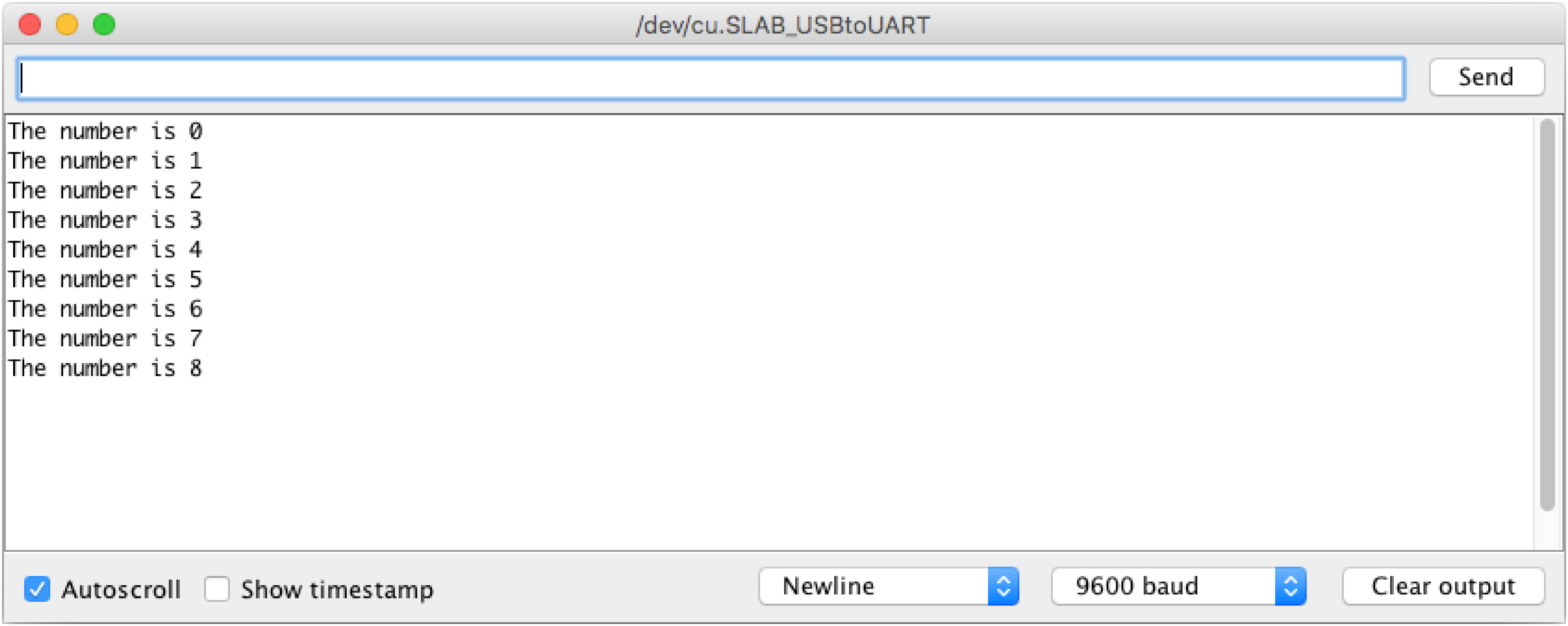
The Arduino IDE (described in Recipe 1.3) provides a Serial Monitor (shown in Figure 4-1) to display serial data sent from Arduino. You can also send data from the Serial Monitor to Arduino by entering text in the text box to the left of the Send button. Arduino also includes a Serial Plotter that can graph serial data sent from Arduino (see Recipe 4.1).

Arduino Serial Monitor screen
You can set the speed at which data is transmitted (the Baud rate, measured in bits per second), using the drop-down box on the bottom right. Make sure to set it to whatever value you use with Serial.begin(). The default rate of 9600 bits per second is fine for many cases, but if you are working with a device that needs a higher speed, you can pass a number higher than 9600 to Serial.begin().
You can use the drop down to the left of the baud rate to automatically send a newline (ASCII character 10), carriage return (ASCII character 13), a combination of newline and carriage return (“Both NL & CR”), or no terminator (“No line ending”) at the end of each message.
Your Arduino sketch can use the serial port to indirectly access (usually via a proxy program written in a language like Processing or Python) all the resources (memory, screen, keyboard, mouse, network connectivity, etc.) that your computer has. Your computer can also use the serial link to interact with certain sensors or other devices connected to Arduino. If you want to talk to multiple devices using serial communications, you either need more than one serial port, or you’ll need to use software serial to emulate a serial port using Arduino pins (“Emulate Serial Hardware with Digital Pins”).
Note
Many sensors and output devices that support serial communications also support SPI or I2C (see Chapter 13). While serial communications are well-understood and somewhat universal, consider using SPI or I2C if either or both are supported by the sensor or output device you want to connect. Both protocols offer more flexibility when communicating with multiple devices.
Implementing serial communications involves hardware and software. The hardware provides the electrical signaling between Arduino and the device it is talking to. The software uses the hardware to send bytes or bits that the connected hardware understands. The Arduino serial libraries insulate you from most of the hardware complexity, but it is helpful for you to understand the basics, especially if you need to troubleshoot any difficulties with serial communications in your projects.
Serial Hardware
Serial hardware sends and receives data as electrical pulses that represent sequential bits. The zeros and ones that carry the information that makes up a byte can be represented in various ways. The scheme used by Arduino is 0 volts to represent a bit value of 0, and 5 volts (or 3.3 volts) to represent a bit value of 1.
Note
Using a device’s low voltage (generally 0 volts) to signify 0 and a high voltage (3.3 or 5 volts in the case of Arduino) to signify 1 is very common. This is referred to as the TTL level because that was how signals were represented in one of the first implementations of digital logic, called Transistor-Transistor Logic (TTL). In most implementations, a 1 can be signaled using less than the device’s high voltage, and 3.3 volts is generally more than enough to signal a 1. This means that you can transmit from a 3.3V board and receive the signal on a 5V board in most cases. However, if you want to transmit serial data from a 5V to a 3.3V board, you will need to use a level shifter or a voltage divider to avoid damaging the 3.3V board. See Recipe 4.13 and Recipe 5.11 for examples of voltage dividers.
Some boards, such as the Modern Device Bare Bones Board and the (now-discontinued) Adafruit Boarduino and Arduino Pro, Mini, and Pro Mini, do not have USB support and require an adapter for connecting to your computer that converts TTL to USB. The Adafruit CP2104 Friend (Adafruit part number 3309), Modern Device USB BUB board (Modern Device part MD022X), and FTDI USB TTL Adapter (http://www.ftdichip.com/Products/Cables/USBTTLSerial.htm) all work well.
Some serial devices use the RS-232 standard for serial connection. These usually have a nine-pin connector, and an adapter is required to use them with the Arduino. RS-232 uses voltage levels that will damage Arduino digital pins so you will need to obtain an RS-232 to TTL adapter to use it. An Arduino RS-232 tutorial is available at https://www.arduino.cc/en/Tutorial/ArduinoSoftwareRS232. Lots of information and links are available at the Serial Port Central website, http://janaxelson.com/serport.htm.
An Arduino Uno has a single hardware serial port, but serial communication is also possible using software libraries to emulate additional ports (communication channels) to provide connectivity to more than one device. Software serial requires a lot of help from the Arduino controller to send and receive data, so it’s not as fast or efficient as hardware serial.
The Leonardo and many 32-bit boards (such as the Arduino Zero, Adafruit Metro M0, and Sparkfun Redboard Turbo) have a second hardware serial port in addition to USB serial. The Teensy 3 board from PJRC (http:// www.pjrc.com/teensy/) has three serial ports in addition to USB serial. The Teensy 4.0 board has seven serial ports (in addition to USB serial).
The Arduino Mega has four hardware serial ports that can communicate with up to four different serial devices. Only one of these has a USB adapter built in (you could wire a USB-TTL adapter to any of the other serial ports if you want more than one USB connection).
Table 4-1 shows the pins used for Serial ports on various Arduino and Arduino-compatible boards. The pin numbers shown are for digital, rather than analog, pins.
| Board | Serial RX/TX | Serial1 RX/TX | Serial2 RX/TX | Serial3 RX/TX |
|---|---|---|---|---|
|
Arduino MKR 1010 |
USB only |
13/14 |
none |
none |
|
Arduino Uno WiFi Rev2 |
USB only |
0/1 |
Connected to WiFi module |
none |
|
Arduino Nano Every |
USB only |
0/1 |
none |
none |
|
Arduino Nano 33 BLE Sense |
USB only |
0/1 |
none |
none |
|
Arduino Uno Rev3 |
0/1 (Also USB) |
none |
none |
none |
|
Adafruit Metro Express (M0) |
USB only |
0/1 |
none |
none |
|
Arduino Zero/SparkFun RedBoard Turbo |
USB onlya |
0/1 |
none |
none |
|
Adafruit Itsy Bitsy M4 Express |
USB only |
0/1 |
none |
none |
|
PJRC Teensy 3.2 |
USB only |
0/1 |
9/10 |
7/8 |
|
PJRC Teensy 4.0 |
USB only |
0/1 |
7/8 |
15/14 |
|
Arduino Due |
0/1 (Also USB) |
19/18 |
17/16 |
15/14 |
|
Arduino Mega 2560 Rev2 |
0/1 (Also USB) |
19/18 |
17/16 |
15/14 |
|
Arduino Leonardo |
USB only |
0/1 |
none |
none |
a Use | ||||
Note
Some Teensy boards support more than three hardware serial ports, and some allow you to modify which pins are used for serial communications. See https://www.pjrc.com/teensy/td_uart.html for more details.
Serial Hardware Behavior
The number of serial ports isn’t the only variable between boards. There are some fundamental differences in behavior, as well. Most boards based on the AVR ATmega chips, including the Uno, original Nano, and Mega have a chip to convert the hardware serial port on the Arduino chip to Universal Serial Bus (USB) for connection to the hardware serial port. On these boards, when you open a connection to the serial port (such as by opening the Serial Monitor or accessing the serial port from a program running on a computer connected to the board via USB), the board will automatically reset, causing the sketch to start from the beginning.
On some 8-bit boards (Leonardo and compatibles) and most 32-bit boards, USB serial is provided by the same processor that you run your sketches on. Because of how they are designed, opening the USB serial port does not reset these boards. As a result, your sketch will begin sending data to the USB serial port faster than you can open the serial port. This means that if you have any serial output commands (Serial.print or Serial.println) in your setup() function, you won’t see it in the Serial Monitor because you can’t open the Serial Monitor quickly enough. (You could put a delay in your setup function, but there is another way).
Additionally, the Leonardo and compatibles have another behavior that makes working with the serial port tricky: when you first power it up, it will flash an LED for several seconds to tell you that it’s in a special mode where it allows you to load a sketch over USB. So you will not be able to open the serial port to send or receive data until it’s done waiting.
On boards that do not reset automatically when you open the serial port, you can add the following code to your setup function (right after the call to Serial.begin()). This will pause execution until the serial port has been opened so you can see serial output that you send in setup:
while(!Serial){;// wait for serial port to connect}
You can skip the curly brackets and consolidate it down to while(!Serial); but this may be confusing to novice programmers who read your code.
Because the while(!Serial); command will pause execution of the sketch until you open the serial port, this approach should not be used in environments where your Arduino-based solution is expected to run independently, for example when running on batteries without a USB connection. Table 4-2 shows USB serial behavior for various boards.
| Board | while(!Serial); needed? |
Resets when serial accessed? |
|---|---|---|
|
Arduino MKR 1010 |
Yes |
No |
|
Arduino Uno WiFi Rev2 |
No |
Yes |
|
Arduino Nano Every |
No; Requires a |
No |
|
Arduino Nano 33 BLE Sense |
Yes |
No |
|
Arduino Uno Rev3 |
No |
Yes |
|
Adafruit Metro Express (M0) |
Yes |
No |
|
Adafruit Itsy Bitsy M4 Express |
Yes |
No |
|
PJRC Teensy 3.2 |
Yes |
No |
|
PJRC Teensy 4.0 |
Yes |
No |
|
Arduino Mega 2560 Rev3 |
No |
Yes |
|
Arduino Leonardo |
Yes |
No |
Emulate Serial Hardware with Digital Pins
You will usually use the built-in Arduino Serial library to communicate with the hardware serial ports. Serial libraries simplify the use of the serial ports by insulating you from hardware complexities.
Sometimes you need more serial ports than the number of hardware serial ports available. If this is the case, you can use an additional software serial library that uses software to emulate serial hardware. Recipes 4.114.11 and 4.12 show how to use a software serial library to communicate with multiple devices.
Message Protocols
The hardware or software serial libraries handle sending and receiving information. This information often consists of groups of variables that need to be sent together. For the information to be interpreted correctly, the receiving side needs to recognize where each message begins and ends. Meaningful serial communication, or any kind of machine-to-machine communication, can only be achieved if the sending and receiving sides fully agree how information is organized in the message. The formal organization of information in a message and the range of appropriate responses to requests is called a communications protocol. You can establish a protocol over any underlying data transfer system, such as serial communications, but these same principles apply to other means of data transfer, such as Ethernet or WiFi networking.
Messages can contain one or more special characters that identify the start of the message—this is called the header. One or more characters can also be used to identify the end of a message—this is called the footer. The recipes in this chapter show examples of messages in which the values that make up the body of a message can be sent in either text or binary format.
Sending and receiving messages in text format involves sending commands and numeric values as human-readable letters and words. Numbers are sent as the string of digits that represent the value. For example, if the value is 1234, the characters 1, 2, 3, and 4 are sent as individual characters.
Binary messages comprise the bytes that the computer uses to represent values. Binary data is usually more efficient (requiring fewer bytes to be sent), but the data is not as human-readable as text, which makes it more difficult to debug. For example, Arduino represents 1234 as the bytes 4 and 210 (4 * 256 + 210 = 1234). If you were to look at these characters in the Serial monitor, they wouldn’t be readable because the ASCII character 4 is a control character and the ASCII character 210 is in the extended range of ASCII characters, so it will probably display an accented character or something else depending on your configuration. If the device you are connecting to sends or receives only binary data, that is what you will have to use, but if you have the choice, textual messages are easier to implement and debug.
There are many ways to approach software problems, and some of the recipes in this chapter show two or three different ways to achieve a similar result. The differences (e.g., sending text instead of raw binary data) may offer a different balance between simplicity and efficiency. Where choices are offered, pick the solution that you find easiest to understand and adapt—this will probably be the first solution covered. Alternatives may be a little more efficient, or they may be more appropriate for a specific protocol that you want to connect to, but the “right way” is the one you find easiest to get working in your project.
Arduino Serial Notes
Here are a few things you should be aware of when working with serial data in Arduino:
-
Serial.flushwaits for all outgoing data to be sent rather than discarding received data (which was the behavior in older versions of Arduino). You can use the following statement to discard all data in the receive buffer:while(Serial.read() >= 0) ; // flush the receive buffer -
Serial.writeandSerial.printdo not block. Older versions of Arduino would wait until all characters were sent before returning. Instead, characters that you send usingSerial.writeorSerial.print(andprintln) are transmitted in the background (from an interrupt handler) allowing your sketch code to immediately resume processing. This is usually a good thing (it can make the sketch more responsive) but sometimes you want to wait until all characters are sent. You can achieve this by callingSerial.flush()immediately followingSerial.write()orSerial.print()/println(). -
Serial print functions return the number of characters printed. This is useful when text output needs to be aligned or for applications that send data that includes the total number of characters sent.
-
There is a built-in parsing capability for streams such as Serial to easily extract numbers and find text. See the Discussion section of Recipe 4.5 for more on using this capability with Serial.
-
The SoftwareSerial library bundled with Arduino can be very helpful; see Recipes 4.11 and 4.12.
-
The
Serial.peekfunction lets you ‘peek’ at the next character in the receive buffer. UnlikeSerial.read, the character is not removed from the buffer withSerial.peek.
4.1 Sending Information from Arduino to Your Computer
Problem
You want to send text and data to be displayed on your PC, Mac, or other device (such as a Raspberry Pi) using the Arduino IDE or the serial terminal program of your choice.
Solution
This sketch prints sequential numbers on the Serial Monitor:
/*
 * SerialOutput sketch
 * Print numbers to the serial port
*/
void setup()
{
  Serial.begin(9600); // send and receive at 9600 baud
}

int number = 0;

void loop()
{
  Serial.print("The number is ");
  Serial.println(number);    // print the number

  delay(500); // delay half second between numbers
  number++; // to the next number
}
Connect Arduino to your computer just as you did in Chapter 1 and upload this sketch. Click the Serial Monitor icon in the IDE and you should see the output displayed as follows:
The number is 0
The number is 1
The number is 2
Discussion
To display text and numbers from your sketch on a computer via a serial link, put the Serial.begin(9600) statement in setup(), and then use Serial.print() statements to print the text and values you want to see.
Arduino Serial Monitor screen
To get a graphical display of the number being sent back close the Serial Monitor window and Select Tools>Serial Plotter A window will open and draw a graph of the values as they are received from the board. The plotter is able to isolate the numbers from the text, and is able to identify multiple numbers separated by alpha characters and plot them separately using different color traces. Figure 4-3 shows the Serial Plotter.

Serial Plotter
Your sketch must call the Serial.begin() function before it can use serial input or output. The function takes a single parameter: the desired communication speed. You must use the same speed for the sending side and the receiving side, or you will see gobbledygook (or nothing at all) on the screen. This example and most of the others in this book use a speed of 9,600 baud (baud is a measure of the number of bits transmitted per second). The 9,600 baud rate is approximately 1,000 characters per second. You can send at lower or higher rates (the range is 300 to 115,200 or higher depending on your board’s capabilities), but make sure both sides use the same speed. The Serial Monitor sets the speed using the baud rate drop down (at the bottom right of the Serial Monitor window in Figure 4-2). If your output looks something like this:
`3??f<ÌxÌ▯▯▯ü`³??f<
you should check that the selected baud rate on the serial monitor on your computer matches the rate set by Serial.begin() in your sketch.
Note
If your send and receive serial speeds are set correctly but you are still getting unreadable text, check that you have the correct board selected in the IDE Tools→Board menu. There are chip speed variants of some boards, if you have selected the wrong one, change it to the correct one and upload to the board again.
You can transmit text using the Serial.print() function. Strings (text within double quotes) will be printed as is (but without the quotes). For example, the following code:
Serial.print("The number is ");
prints this:
The number is
The values (numbers) that you print depend on the type of variable; see Recipe 4.2 for more about this. For example, printing an integer will print its numeric value, so if the variable number is 1, the following code:
Serial.println(number);
will print whatever the current value of number happens to be:
1
In the example sketch, the number printed will be 0 when the loop starts and will increase by one each time through the loop. The ln at the end of println causes the next print statement to start on a new line.
Note
Keep in mind that there are two different serial port behaviors you will encounter with Arduino and Arduino-compatible boards: the Uno and most other AVR ATmega-based boards will reset when you open the serial port. This means that you will always see the count begin at zero in the Serial Monitor or Plotter. The Arduino Leonardo, as well as ARM-based boards, do not automatically reset when you open the serial port. This means that the sketch will begin counting as soon as it is powered up. As a result, the value that you see when you first open the Serial Monitor or Plotter depends on when you open the serial connection to the board. See “Serial Hardware Behavior” for more details.
That should get you started printing text and the decimal value of integers. See Recipe 4.2 for more detail on print formatting options.
You may want to consider a third-party terminal program that has more features than Serial Monitor. Displaying data in text or binary format (or both), displaying control characters, and logging to a file are just a few of the additional capabilities available from the many third-party terminal programs. Here are some that have been recommended by Arduino users:
- CoolTerm
-
An easy-to-use freeware terminal program for Windows, Mac, and Linux
- CuteCom
-
An open source terminal program for Linux
- Bray Terminal
-
A free executable for the PC
- GNU screen
-
An open source virtual screen management program that supports serial communications; included with Linux and macOS
- moserial
-
Another open source terminal program for Linux
- PuTTY
-
An open source SSH program for Windows and Linux that supports serial communications
- RealTerm
-
An open source terminal program for the PC
- ZTerm
-
A shareware program for the Mac
You can use a liquid crystal display (LCD) as a serial output device, although it will be very limited in functionality. Check the documentation to see how your display handles carriage returns, as some displays may not automatically advance to a new line after println statements. Also, when you are using an LCD display, you will be connecting to it using the TTL serial pins (digital 0 and 1) rather than a USB connection. On most AVR ATmega boards like the Uno, these pins correspond to the Serial object so you can use the code shown in the Solution unchanged. However, on the Leonardo or certain ARM-based boards (SAMD-based boards for example), pins 0 and 1 correspond to the Serial1 object, so you’ll need to change Serial to Serial1 in order for it to work on those boards. See Table 4-1 for a list of Serial object pin configurations for a variety of boards.
See Also
The Arduino LiquidCrystal library for text LCDs uses underlying print functionality similar to the Serial library, so you can use many of the suggestions covered in this chapter with that library (see Chapter 11).
4.2 Sending Formatted Text and Numeric Data from Arduino
Problem
You want to send serial data from Arduino displayed as text, decimal values, hexadecimal, or binary.
Solution
You can print data to the serial port in many different formats; here is a sketch that demonstrates all the format options available with the serial print functions print() and println:
/*
  SerialFormatting
  Print values in various formats to the serial port
*/
char chrValue  = 65;  // these are the starting values to print
byte byteValue = 65;
int intValue   = 65;
float floatValue = 65.0;
char c1 = 4;
char c2 = 210;

void setup()
{
  while(!Serial); // Wait until serial port's open on Leonardo and SAMD boards
  Serial.begin(9600);
}

void loop()
{
  Serial.print("chrValue:   ");
  Serial.print(chrValue); Serial.print(" ");
  Serial.write(chrValue); Serial.print(" ");
  Serial.print(chrValue, DEC);
  Serial.println();

  Serial.print("byteValue:  ");
  Serial.print(byteValue); Serial.print(" ");
  Serial.write(byteValue); Serial.print(" ");
  Serial.print(byteValue, DEC);
  Serial.println();

  Serial.print("intValue:   ");
  Serial.print(intValue); Serial.print(" ");
  Serial.print(intValue, DEC); Serial.print(" ");
  Serial.print(intValue, HEX); Serial.print(" ");
  Serial.print(intValue, OCT); Serial.print(" ");
  Serial.print(intValue, BIN);
  Serial.println();

  Serial.print("floatValue: ");
  Serial.println(floatValue);
  Serial.println();

  delay(1000); // delay a second between numbers
  chrValue++;  // to the next value
  byteValue++;
  intValue++;
  floatValue += 1;
}
The output is as follows:
chrValue:   A A 65
byteValue:  65 A 65
intValue:   65 65 41 101 1000001
floatValue: 65.00

chrValue:   B B 66
byteValue:  66 B 66
intValue:   66 66 42 102 1000010
floatValue: 66.00
...
Discussion
Printing a text string is simple: Serial.print("hello world"); sends the text string “hello world” to a device at the other end of the serial port. If you want your output to print a new line after the output, use Serial.println() instead of Serial.print().
Printing numeric values can be more complicated. The way that byte and integer values are printed depends on the type of variable and an optional formatting parameter. The Arduino language is very easygoing about how you can refer to the value of different data types (see Recipe 2.2 for more on data types). But this flexibility can be confusing, because even when the numeric values are similar, the compiler considers them to be separate types with different behaviors. For example, printing a char, byte, and int of the same value will not necessarily produce the same output.
Here are some specific examples; all of them create variables that have similar values:
char asciiValue  = 'A';   // ASCII A has a value of 65
char chrValue    = 65;    // an 8-bit signed character, this also is ASCII 'A'
byte byteValue   = 65;    // an 8-bit unsigned character, this also is ASCII 'A'
int intValue     = 65;    // a 16-bit signed integer set to a value of 65
float floatValue = 65.0;  // float with a value of 65
Table 4-3 shows what you will see when you print variables using Arduino routines.
| Data type | print (val) |
print (val,DEC) |
write (val) |
print (val,HEX) |
print (val,OCT) |
print (val,BIN) |
|---|---|---|---|---|---|---|
|
|
|
|
|
|
|
|
|
|
|
|
|
|
|
|
|
|
|
|
|
|
|
|
|
|
Format of |
|||||
|
|
|
Formatting not supported for floating-point values |
||||
|
|
|
|
Note
The expression Serial.print(val,BYTE); is no longer supported in Arduino versions from 1.0.
If your code expects byte variables to behave the same as char variables (that is, for them to print as ASCII), you will need to change this to Serial.write(val);.
The sketch in this recipe uses a separate line of source code for each print statement. This can make complex print statements bulky. For example, to print the following line:
At 5 seconds: speed = 17, distance = 120
you’d typically have to code it like this:
Serial.print("At ");
Serial.print(t);
Serial.print(" seconds: speed = ");
Serial.print(s);
Serial.print(", distance = ");
Serial.println(d);
That’s a lot of code lines for a single line of output. You could combine them like this:
Serial.print("At "); Serial.print(t); Serial.print(" seconds, speed = ");
Serial.print(s); Serial.print(", distance = ");Serial.println(d);
Or you could use the insertion-style capability of the compiler used by Arduino to format your print statements. You can take advantage of some advanced C++ capabilities (streaming insertion syntax and templates) that you can use if you declare a streaming template in your sketch. This is most easily achieved by including the Streaming library developed by Mikal Hart. You can read more about this library at Mikal’s website, and you can install it using the Recipe 16.2.
If you use the Streaming library, the following gives the same output as the lines shown earlier:
Serial << "At " << t << " seconds, speed = " << s << ", distance = " << d << endl;
If you are an experienced programmer you may be wondering why Arduino does not support printf. In part this is due to printf’s use of dynamic memory and the shortage of RAM on the 8-bit boards. Recent 32-bit boards have plenty of memory, however the Arduino team has been reluctant to include the terse and easily abused syntax as part of the Arduino language’s Serial output capabilities.
Although Arduino does not include support for printf, you can use its sibling sprintf to store formatted text in a character buffer, and then print that buffer using Serial.print/println:
char buf[100];
sprintf(buf, "At %d seconds, speed = %d, distance = %d", t, s, d);
Serial.println(buf);
But sprintf can be dangerous. If the string you’re writing is larger than your buffer, it will overflow. It’s anyone’s guess as to where the overflow characters will be written, but almost certainly they will cause your sketch to crash or otherwise misbehave. The snprintf function allows you to pass an argument specifying the maximum number of characters (including the null character that terminates all strings). You can specify the same length you use to declare the array (in this case, 100), but if you do that, you need to remember to change the length argument if you change the buffer length. Instead, you can use the sizeof operator to calculate the length of the buffer. Although a char is 1 byte in every case we can think of, it’s best practice to divide the size of the array by the size of the datatype it contains, so sizeof (buf) / sizeof (buf[0]) will give you the length of the array:
snprintf(buf, sizeof (buf) / sizeof (buf[0]),
         "At %d seconds, speed = %d, distance = %d", t, s, d);
Serial.println(buf);
Note
Even though you know that sizeof (buf[0]) is guaranteed to be 1, this is a good habit to get into. Consider the following code, which prints 400:
long buf2[100];
Serial.println(sizeof (buf2));
You can get the correct result with sizeof (buf2) / sizeof (buf2[0])
There is a cost associated with using sprintf or snprintf. First, you’ve got the overhead of the buffer, 100 bytes in this case. Additionally, there is the overhead of compiling the functionality into your sketch. On an Arduino Uno, adding in this code increases your memory usage by 1648 bytes, which is 5% of the Uno’s memory.
See Also
Chapter 2 provides more information on data types used by Arduino. The Arduino web reference at https://www.arduino.cc/reference/en/ covers the serial commands, and the Arduino web reference at http://www.arduino.cc/playground/Main/StreamingOutput covers streaming (insertion-style) output.
4.3 Receiving Serial Data in Arduino
Problem
You want to receive data on Arduino from a computer or another serial device; for example, to have Arduino react to commands or data sent from your computer.
Solution
This sketch receives a digit (single characters 0 through 9) and blinks the onboard LED at a rate proportional to the received digit value:
/*
 * SerialReceive sketch
 * Blink the LED at a rate proportional to the received digit value
*/
int blinkDelay = 0;  // blink delay stored in this variable

void setup()
{
  Serial.begin(9600); // Initialize serial port to send and receive at 9600 baud
  pinMode(LED_BUILTIN, OUTPUT); // set this pin as output
}

void loop()
{
  if (Serial.available()) // Check to see if at least one character is available
  {
    char ch = (char) Serial.read();
    if( isDigit(ch) ) // is this an ascii digit between 0 and 9?
    {
      blinkDelay = (ch - '0');       // ASCII value converted to numeric value
      blinkDelay = blinkDelay * 100; // actual delay is 100ms times received digit
    }
  }
  blink();
}

// blink the LED with the on and off times determined by blinkDelay
void blink()
{
  digitalWrite(LED_BUILTIN, HIGH);
  delay(blinkDelay); // delay depends on blinkDelay value
  digitalWrite(LED_BUILTIN, LOW);
  delay(blinkDelay);
}
Upload the sketch and send messages using the Serial Monitor. Open the Serial Monitor by clicking the Monitor icon (see Recipe 4.1) and type a digit in the text box at the top of the Serial Monitor window. Clicking the Send button will send the character typed into the text box; if you type a digit, you should see the blink rate change.
Discussion
The Serial.read function returns an int value, so you should cast it to a char for the comparisons that follow. Converting the received ASCII characters to numeric values may not be obvious if you are not familiar with the way ASCII represents characters. The following converts the character ch to its numeric value:
blinkDelay = (ch - '0'); // ASCII value converted to numeric value
The ASCII characters ‘0’ through ‘9’ have a value of 48 through 57 (see Appendix G). Converting ‘1’ to the numeric value one is done by subtracting ‘0’ because ‘1’ has an ASCII value of 49, so 48 (ASCII ‘0’) must be subtracted to convert this to the number one. For example, if ch is representing the character 1, its ASCII value is 49. The expression 49- '0' is the same as 49-48. This equals 1, which is the numeric value of the character 1.
In other words, the expression (ch - '0') is the same as (ch - 48); this converts the ASCII value of the variable ch to a numeric value.
You can receive numbers with more than one digit using the parseInt and parseFloat methods that simplify extracting numeric values from Serial (it also works with Ethernet and other objects derived from the Stream class; see the introduction to Chapter 15 for more about stream-parsing with the networking objects).
Serial.parseInt() and Serial.parseFloat() read Serial characters and return their numeric representation. Non-numeric characters before the number are ignored and the number ends with the first character that is not a numeric digit (or ‘.’ if using parseFloat.) If there aren’t any numeric characters in the input, the functions return 0, so you should check for zero values and handle them appropriately. If you have the Serial Monitor configured to send a newline, carriage return (or both) when you click Send, parseInt or parseFloat will try (and fail) to interpret the newline or carriage return as a number, and return a zero. This would result in blinkDelay being set to zero immediately after setting it to your intended value, which would result in no blinking.
/*
* SerialParsing sketch
* Blink the LED at a rate proportional to the received digit value
*/

int blinkDelay = 0;

void setup()
{
  Serial.begin(9600); // Initialize serial port to send and receive at 9600 baud
  pinMode(LED_BUILTIN, OUTPUT); // set this pin as output
}

void loop()
{
  if ( Serial.available()) // Check to see if at least one character is available
  {
    int i = Serial.parseInt();
    if (i != 0) {
        blinkDelay = i;
    }
  }
  blink();
}

// blink the LED with the on and off times determined by blinkDelay
void blink()
{
  digitalWrite(LED_BUILTIN, HIGH);
  delay(blinkDelay); // delay depends on blinkDelay value
  digitalWrite(LED_BUILTIN, LOW);
  delay(blinkDelay);
}
See the discussion of Recipe 4.5 for another example showing parseInt used to find and extract numbers from Serial data.
Another approach to converting text strings representing numbers is to use the C language conversion function called atoi (for int variables) or atol (for long variables). These obscurely named functions convert a string into integers or long integers. These provide more capability to manipulate the incoming data at the cost of greater code complexity. To use these functions you have to receive and store the entire string in a character array before you can call the conversion function.
This code fragment terminates the incoming digits on any character that is not a digit (or if the buffer is full):
const int maxChars = 5;    // an int string contains up to 5 digits and
                           // is terminated by a 0 to indicate end of string
char strValue[maxChars+1]; // must be big enough for digits and terminating null
int idx = 0;               // the index into the array storing the received digits

void loop()
{
  if( Serial.available())
  {
    char ch = (char) Serial.read();
    if( idx < maxChars && isDigit(ch) ){
      strValue[idx++] = ch; // add the ASCII character to the string;
    }
    else
    {
      // here when buffer full or on the first non digit
      strValue[idx] = 0;           // terminate the string with a 0
      blinkDelay = atoi(strValue); // use atoi to convert the string to an int
      idx = 0;
    }
  }
  blink();
}
strValue is a numeric string built up from characters received from the serial port.
Note
See Recipe 2.6 for information about character strings.
atoi (short for ASCII to integer) is a function that converts a character string to an integer (atol converts to a long integer).
Arduino also supports the serialEvent function that you can use to handle incoming serial characters. If you have code within a serialEvent function in your sketch, this will be called once each time through the loop function. The following sketch performs the same function as the first sketch in this Recipe but uses serialEvent to handle the incoming characters:
/*
 * SerialEvent Receive sketch
 * Blink the LED at a rate proportional to the received digit value
 */
int blinkDelay = 0;     // blink delay stored in this variable

void setup()
{
  Serial.begin(9600); // Initialize serial port to send and receive at 9600 baud
  pinMode(LED_BUILTIN, OUTPUT); // set this pin as output
}

void loop()
{
  blink();
}

void serialEvent()
{
  while(Serial.available())
  {
    char ch = (char) Serial.read();
    Serial.write(ch);
    if( isDigit(ch) ) // is this an ascii digit between 0 and 9?
    {
      blinkDelay = (ch - '0');       // ASCII value converted to numeric value
      blinkDelay = blinkDelay * 100; // actual delay is 100mS times received digit
    }
  }
}

// blink the LED with the on and off times determined by blinkDelay
void blink()
{
  digitalWrite(LED_BUILTIN, HIGH);
  delay(blinkDelay); // delay depends on blinkDelay value
  digitalWrite(LED_BUILTIN, LOW);
  delay(blinkDelay);
}
See Also
A web search for “atoi” or “atol” provides many references to these functions. Also see the Wikipedia reference at http://en.wikipedia.org/wiki/Atoi.
4.4 Sending Multiple Text Fields from Arduino in a Single Message
Problem
You want to send a message that contains more than one field’s worth of information per message. For example, your message may contain values from two or more sensors. You want to use these values in a program such as Processing, running on a computer or a device such as a Raspberry Pi.
Solution
An easy way to do this is to send a text string with all the fields separated by a delimiting (separating) character, such as a comma:
// CommaDelimitedOutput sketch

void setup()
{
  Serial.begin(9600);
}

void loop()
{
  int value1 = 10;    // some hardcoded values to send
  int value2 = 100;
  int value3 = 1000;

  Serial.print('H'); // unique header to identify start of message
  Serial.print(",");
  Serial.print(value1,DEC);
  Serial.print(",");
  Serial.print(value2,DEC);
  Serial.print(",");
  Serial.print(value3,DEC);
  Serial.println();  // send a carriage return and line feed
  delay(100);
}
Here is the Processing sketch that reads this data from the serial port:
// Processing Sketch to read comma delimited serial
// expects format: H,1,2,3

import processing.serial.*;

Serial myPort;        // Create object from Serial class
char HEADER = 'H';    // character to identify the start of a message
short LF = 10;        // ASCII linefeed

// WARNING!
// If necessary change the definition below to the correct port
short portIndex = 0;  // select the com port, 0 is the first port

void setup() {
  size(200, 200);
  println( (Object[]) Serial.list());
  println(" Connecting to -> " + Serial.list()[portIndex]);
  myPort = new Serial(this, Serial.list()[portIndex], 9600);
}

void draw() {
  if (myPort.available() > 0) {

    String message = myPort.readStringUntil(LF); // read serial data
    if (message != null)
    {
      message = message.trim(); // Remove whitespace from start/end of string
      println(message);
      String [] data = message.split(","); // Split the comma-separated message
      if (data[0].charAt(0) == HEADER && data.length == 4) // check validity
      {
        for (int i = 1; i < data.length; i++) // skip header (start at 1, not 0)
        {
          println("Value " +  i + " = " + data[i]);  // Print the field values
        }
        println();
      }
    }
  }
}
Discussion
The Arduino code in this recipe’s Solution will send the following text string to the serial port (
indicates a carriage return and
indicates a line feed):
H,10,100,1000
You must choose a separating character that will never occur within actual data; if your data consists only of numeric values, a comma is a good choice for a delimiter. You may also want to ensure that the receiving side can determine the start of a message to make sure it has all the data for all the fields. You do this by sending a header character to indicate the start of the message. The header character must also be unique; it should not appear within any of the data fields and it must also be different from the separator character. The example here uses an uppercase H to indicate the start of the message. The message consists of the header, three comma-separated numeric values as ASCII strings, and a carriage return and line feed.
The carriage return and line-feed characters are sent whenever Arduino prints using the println() function, and this is used to help the receiving side know that the full message string has been received. Because the Processing code myPort.readStringUntil(LF) will include the carriage return ('
') that appears before the line feed, this sketch uses trim() to remove any leading or trailing whitespace, which includes spaces, tabs, carriage returns, and line feeds.
The Processing code reads the message as a string and uses the Java split() method to create an array from the comma-separated fields.
Note
In most cases, the first serial port will be the one you want when using a Mac (or a PC without a physical RS-232 port) and the last serial port will be the one you want when using a PC that has a physical RS-232 port. The Processing sketch includes code that shows the ports available and the one currently selected, so you need to check that this is the port connected to Arduino. You may need to run the sketch once, get an error, and review the list of serial ports in the Processing Console at the bottom of the screen to determine which value you should use for portIndex.
Using Processing to display sensor values can save hours of debugging time by helping you to visualize the data. While CSV is a common and useful format, JSON (JavaScript Object Notation) is more expressive and also is human readable. JSON is a common data exchange format used for exchanging messages across a network. The following sketch reads the accelerometer from the Arduino WiFi Rev 2 or Arduino Nano 33 BLE Sense (uncomment the corresponding include line) and sends it to the serial port using JSON, for example: {'x': 0.66, 'y': 0.59, 'z': -0.49, }
/*
   AccelerometerToJSON. Sends JSON-formatted representation of
   accelerometer readings.
*/

#include <Arduino_LSM6DS3.h>   // Arduino WiFi R2
//#include <Arduino_LSM9DS1.h> // Arduino BLE Sense

void setup() {
  Serial.begin(9600);
  while (!Serial);

  if (!IMU.begin()) {
    while (1) {
      Serial.println("Error: Failed to initialize IMU");
      delay(3000);
    }
  }
}

void loop() {
  float x, y, z;
  if (IMU.accelerationAvailable()) {
    IMU.readAcceleration(x, y, z);
    Serial.print("{");
    Serial.print("'x': "); Serial.print(x); Serial.print(", ");
    Serial.print("'y': "); Serial.print(y); Serial.print(", ");
    Serial.print("'z': "); Serial.print(z); Serial.print(", ");
    Serial.println("}");
    delay(200);
  }
}
The following Processing sketch adds real-time visual display of up to 12 values sent from Arduino. It displays floating-point values in a range from –5 to +5:
/*
 * ShowSensorData.
 *
 * Displays bar graph of JSON sensor data ranging from -127 to 127
 * expects format as: "{'label1': value, 'label2': value,}
"
 * for example:
 * {'x': 1.0, 'y': -1.0, 'z': 2.1,}
 */

import processing.serial.*;
import java.util.Set;

Serial myPort;  // Create object from Serial class
PFont fontA;    // font to display text
int fontSize = 12;
short LF = 10;        // ASCII linefeed

int rectMargin  = 40;
int windowWidth = 600;
int maxLabelCount = 12; // Increase this if you need to support more labels
int windowHeight  = rectMargin + (maxLabelCount + 1) * (fontSize *2);
int rectWidth  = windowWidth - rectMargin*2;
int rectHeight = windowHeight - rectMargin;
int rectCenter = rectMargin + rectWidth / 2;

int origin = rectCenter;
int minValue = -5;
int maxValue = 5;

float scale = float(rectWidth) / (maxValue - minValue);

// WARNING!
// If necessary change the definition below to the correct port
short portIndex = 0;  // select the com port, 0 is the first port

void settings() {
  size(windowWidth, windowHeight);
}

void setup() {
  println( (Object[]) Serial.list());
  println(" Connecting to -> " + Serial.list()[portIndex]);
  myPort = new Serial(this, Serial.list()[portIndex], 9600);
  fontA = createFont("Arial.normal", fontSize);
  textFont(fontA);
}

void draw() {

  if (myPort.available () > 0) {
    String message = myPort.readStringUntil(LF);
    if (message != null) {

      // Load the JSON data from the message
      JSONObject json = new JSONObject();
      try {
        json = parseJSONObject(message);
      }
      catch(Exception e) {
        println("Could not parse [" + message + "]");
      }

      // Copy the JSON labels and values into separate arrays.
      ArrayList<String> labels = new ArrayList<String>();
      ArrayList<Float> values = new ArrayList<Float>();
      for (String key : (Set<String>) json.keys()) {
        labels.add(key);
        values.add(json.getFloat(key));
      }

      // Draw the grid and chart the values
      background(255);
      drawGrid(labels);
      fill(204);
      for (int i = 0; i < values.size(); i++) {
        drawBar(i, values.get(i));
      }
    }
  }
}

// Draw a bar to represent the current sensor reading
void drawBar(int yIndex, float value) {
  rect(origin, yPos(yIndex)-fontSize, value * scale, fontSize);
}

void drawGrid(ArrayList<String> sensorLabels) {
  fill(0);

  // Draw the minimum value label and a line for it
  text(minValue, xPos(minValue), rectMargin-fontSize);
  line(xPos(minValue), rectMargin, xPos(minValue), rectHeight + fontSize);

  // Draw the center value label and a line for it
  text((minValue+maxValue)/2, rectCenter, rectMargin-fontSize);
  line(rectCenter, rectMargin, rectCenter, rectHeight + fontSize);

  // Draw the maximum value label and a line for it
  text(maxValue, xPos(maxValue), rectMargin-fontSize);
  line(
  xPos(maxValue), rectMargin, xPos(maxValue), rectHeight + fontSize);

  // Print each sensor label
  for (int i=0; i < sensorLabels.size(); i++) {
    text(sensorLabels.get(i), fontSize, yPos(i));
    text(sensorLabels.get(i), xPos(maxValue) + fontSize, yPos(i));
  }
}

// Calculate a y position, taking into account margins and font sizes
int yPos(int index) {
  return rectMargin + fontSize + (index * fontSize*2);
}

// Calculate a y position, taking into account the scale and origin
int xPos(int value) {
  return origin  + int(scale * value);
}
Figure 4-4 shows how accelerometer values (x, y, z) values are displayed. Bars will appear as you wave the device.

Processing screen showing sensor data
The range of values and the origin of the graph can be easily changed if desired. For example, to display bars originating at the lefthand axis with values from 0 to 1024, use the following:
int origin = rectMargin; // rectMargin is the left edge of the graphing area
int minValue = 0;
int maxValue = 1024;
If you don’t have an accelerometer, you can generate values with the following simple sketch that displays analog input values. If you don’t have any sensors to connect, running your fingers along the bottom of the analog pins will produce levels that can be viewed in the Processing sketch. The values range from 0 to 1023, so change the origin and min and max values in the Processing sketch, as described in the previous paragraph:
/*
   AnalogToJSON. Sends JSON-formatted representation of
   analog readings.
*/

void setup() {
  Serial.begin(9600);
  while (!Serial);
}

void loop() {
  Serial.print("{");
  Serial.print("'A0': "); Serial.print(analogRead(A0)); Serial.print(", ");
  Serial.print("'A1': "); Serial.print(analogRead(A1)); Serial.print(", ");
  Serial.print("'A2': "); Serial.print(analogRead(A2)); Serial.print(", ");
  Serial.print("'A3': "); Serial.print(analogRead(A3)); Serial.print(", ");
  Serial.print("'A4': "); Serial.print(analogRead(A4)); Serial.print(", ");
  Serial.print("'A5': "); Serial.print(analogRead(A5)); Serial.print(", ");
  Serial.println("}");
}
See Also
The Processing website provides more information on installing and using this programming environment. See http://processing.org/.
A number of books on Processing are also available:
-
Getting Started with Processing, 2nd Edition by Casey Reas and Ben Fry (Make).
-
Processing: A Programming Handbook for Visual Designers and Artists by Casey Reas and Ben Fry (MIT Press).
-
Visualizing Data by Ben Fry (O’Reilly; search for it on oreilly.com).
-
Processing: Creative Coding and Computational Art by Ira Greenberg (Apress).
-
Making Things Talk by Tom Igoe (Make). This book covers Processing and Arduino and provides many examples of communication code.
4.5 Receiving Multiple Text Fields in a Single Message in Arduino
Problem
You want to receive a message that contains more than one field. For example, your message may contain an identifier to indicate a particular device (such as a motor or other actuator) and what value (such as speed) to set it to.
Solution
Arduino does not have the split() function used in the Processing code in Recipe 4.4, but similar functionality can be implemented as shown in this recipe. The following code receives a message with a single character ‘H’ as the header followed by three numeric fields separated by commas and terminated by the newline character.
/*
 * SerialReceiveMultipleFields sketch
 * This code expects a message in the format: H,12,345,678
 * This code requires a newline character to indicate the end of the data
 * Set the serial monitor to send newline characters
 */

const int NUMBER_OF_FIELDS = 3; // how many comma separated fields we expect
int values[NUMBER_OF_FIELDS];   // array holding values for all the fields

void setup()
{
  Serial.begin(9600); // Initialize serial port to send and receive at 9600 baud
}

void loop()
{
  if ( Serial.available())
  {
    if (Serial.read() == 'H') {

      // Read the values
      for (int i = 0; i < NUMBER_OF_FIELDS; i++)
      {
        values[i] = Serial.parseInt();
      }

      // Display the values in comma-separated format
      Serial.print(values[0]); // First value

      // Print the rest of the values with a leading comma
      for (int i = 1; i < NUMBER_OF_FIELDS; i++)
      {
        Serial.print(","); Serial.print(values[i]);
      }
      Serial.println();
    }
  }
}
Discussion
This sketch uses the parseInt method that makes it easy to extract numeric values from serial and web streams. This is one example of how to use this capability (Chapter 15 has more examples of stream parsing). You can test this sketch by opening the Serial Monitor and sending a comma-separated message like H1,2,3. parseInt ignores anything other than a minus sign and a digit, so it doesn’t have to be comma-separated. You can use another delimiter like H1/2/3. The sketch stores the numbers in an array, and then prints them out, separated by commas.
Note
This sketch displays a comma-separated list in a way that may seem unusual at first. It prints the first number received (for example, 1), and then prints the remaining numbers, each preceded by a comma (for example, ,2 and then ,3). You could use fewer lines of code and print a comma after each number, but you’d end up with 1,2,3, instead of 1,2,3. Many other programming languages, including Processing, provide a join function that will combine an array into a delimited string, but Arduino does not.
The stream-parsing functions will time out waiting for a character; the default is one second. If no digits have been received and parseInt times out then it will return 0. You can change the timeout by calling Stream.setTimeout(timeoutPeriod). The timeout parameter is a long integer indicating the number of milliseconds, so the timeout range is from 1 millisecond to 2,147,483,647 milliseconds.
Stream.setTimeout(2147483647); will change the timeout interval to just under 25 days.
Here is a summary of the stream parsing methods supported by Arduino (not all are used in the preceding example):
bool find(char *target);-
Reads from the stream until the given target is found. It returns
trueif the target string is found. A return offalsemeans the data has not been found anywhere in the stream and that there is no more data available. Note that Stream parsing takes a single pass through the stream; there is no way to go back to try to find or get something else (see thefindUntilmethod). bool findUntil(char *target, char *terminate);-
Similar to the
findmethod, but the search will stop if the terminate string is found. Returnstrueonly if the target is found. This is useful to stop a search on a keyword or terminator. For example:finder.findUntil("target", " ");will try to seek to the string
"value", but will stop at a newline character so that your sketch can do something else if the target is not found. long parseInt();-
Returns the first valid (long) integer value. Leading characters that are not digits or a minus sign are skipped. The integer is terminated by the first nondigit character following the number. If no digits are found, the function returns
0. long parseInt(char skipChar);-
Same as
parseInt, but the givenskipCharwithin the numeric value is ignored. This can be helpful when parsing a single numeric value that uses a comma between blocks of digits in large numbers, but bear in mind that text values formatted with commas cannot be parsed as a comma-separated string (for example, 32,767 would be parsed as 32767). float parseFloat();-
The
floatversion ofparseInt. All characters except digits, a decimal point, or a leading minus sign are skipped. size_t readBytes(char *buffer, size_t length);-
Puts the incoming characters into the given buffer until timeout or length characters have been read. Returns the number of characters placed in the buffer.
size_t readBytesUntil(char terminator, char *buf, size_t length);-
Puts the incoming characters into the given buffer until the
terminatorcharacter is detected. Strings longer than the givenlengthare truncated to fit. The function returns the number of characters placed in the buffer.
See Also
Chapter 15 provides more examples of Stream parsing used to find and extract data from a stream. The ArduinoJson library lets you parse JSON-formatted messages (see Recipe 4.4) in Arduino.
4.6 Sending Binary Data from Arduino
Problem
You need to send data in binary format, because you want to pass information with the fewest number of bytes or because the application you are connecting to only handles binary data.
Solution
This sketch sends a header followed by two integer (two byte) values as binary data. The sketch uses short because it will be two bytes regardless of whether you have an 8-bit or 32-bit board (see Recipe 2.2). The values are generated using the Arduino random function (see Recipe 3.11). Although random returns a long value, the argument of 599 means it will never return a value over that number, which is small enough to fit in a short:
/*
 * SendBinary sketch
 * Sends a header followed by two random integer values as binary data.
*/

short intValue; // short integer value (two bytes on all boards)

void setup()
{
  Serial.begin(9600);
}

void loop()
{
  Serial.print('H'); // send a header character

  // send a random integer
  intValue = random(599); // generate a random number between 0 and 599
  // send the two bytes that comprise that integer
  Serial.write(lowByte(intValue));  // send the low byte
  Serial.write(highByte(intValue)); // send the high byte

  // send another random integer
  intValue = random(599); // generate a random number between 0 and 599
  // send the two bytes that comprise that integer
  Serial.write(lowByte(intValue));  // send the low byte
  Serial.write(highByte(intValue)); // send the high byte

  delay(1000);
}
Discussion
Sending binary data requires careful planning, because you will get gibberish unless the sending side and the receiving side understand and agree exactly how the data will be sent. Unlike text data, where the end of a message can be determined by the presence of the terminating carriage return (or another unique character you pick), it may not be possible to tell when a binary message starts or ends by looking just at the data—data that can have any value can therefore have the value of a header or terminator character.
This can be overcome by designing your messages so that the sending and receiving sides know exactly how many bytes are expected. The end of a message is determined by the number of bytes sent rather than detection of a specific character. This can be implemented by sending an initial value to say how many bytes will follow. Or you can fix the size of the message so that it’s big enough to hold the data you want to send. Doing either of these is not always easy, as different platforms and languages can use different sizes for the binary data types—both the number of bytes and their order may be different from Arduino. For example, Arduino defines an int as two bytes (16 bits) on 8-bit platforms, four bytes (32 bits) on a 32-bit platform, and Processing (Java) defines an int as four bytes (short is the Java type for a two-byte integer). Sending an int value as text (as seen in earlier text recipes) simplifies this problem because each individual digit is sent as a sequential digit (just as the number is written). The receiving side recognizes when the value has been completely received by a carriage return or other nondigit delimiter. Binary transfers can only know about the composition of a message if it is defined in advance or specified in the message.
This recipe’s Solution requires an understanding of the data types on the sending and receiving platforms and some careful planning. Recipe 4.7 shows example code using the Processing language to receive these messages.
Sending single bytes is easy; use Serial.write(byteVal). To send an integer from Arduino you need to send the low and high bytes that make up the integer (see Recipe 2.2 for more on data types). You do this using the lowByte and highByte functions (see Recipe 3.14):
Serial.write(lowByte(intValue));
Serial.write(highByte(intValue));
Sending a long integer is done by breaking down the four bytes that comprise a long in two steps. The long is first broken into two 16-bit integers; each is then sent using the method for sending integers described earlier:
long longValue = 2147483648;
int intValue;
First you send the lower 16-bit integer value:
intValue = longValue & 0xFFFF;  // get the value of the lower 16 bits
Serial.write(lowByte(intValue));
Serial.write(highByte(intValue));
Then you send the higher 16-bit integer value:
intValue = longValue >> 16;  // get the value of the higher 16 bits
Serial.write(lowByte(intValue));
Serial.write(highByte(intValue));
You may find it convenient to create functions to send the data. Here is a function that uses the code shown earlier to print a 16-bit integer to the serial port:
// function to send the given integer value to the serial port
void sendBinary(int value)
{
  // send the two bytes that comprise a two byte (16-bit) integer
  Serial.write(lowByte(value));  // send the low byte
  Serial.write(highByte(value)); // send the high byte
}
The following function sends the value of a long (4-byte) integer by first sending the two low (rightmost) bytes, followed by the high (leftmost) bytes:
// function to send the given long integer value to the serial port
void sendBinary(long value)
{
  // first send the low 16-bit integer value
  int temp = value & 0xFFFF;  // get the value of the lower 16 bits
  sendBinary(temp);
  // then send the higher 16-bit integer value:
  temp = value >> 16;  // get the value of the higher 16 bits
  sendBinary(temp);
}
These functions to send binary int and long values have the same name: sendBinary. The compiler distinguishes them by the type of value you use for the parameter. If your code calls printBinary with a 2-byte value, the version declared as void sendBinary(int value) will be called. If the parameter is a long value, the version declared as void sendBinary(long value) will be called. This behavior is called function overloading. Recipe 4.2 provides another illustration of this; the different functionality you saw in Serial.print is due to the compiler distinguishing the different variable types used.
You can also send binary data using structures. Structures are a mechanism for organizing data, and if you are not already familiar with their use you may be better off sticking with the solutions described earlier. For those who are comfortable with the concept of structure pointers, the following will send the bytes within a structure to the serial port as binary data. It includes the header character in the struct, so it sends the same messages as the Solution.
/*
   SendBinaryStruct sketch
   Sends a struct as binary data.
*/

typedef struct {
  char padding; // ensure same alignment on 8-bit and 32-bit
  char header;
  short intValue1;
  short intValue2;
} shortMsg;

void setup()
{
  Serial.begin(9600);
}

void loop()
{

  shortMsg myStruct = { 0, 'H', (short) random(599), (short) random(599) };
  sendStructure((byte *)&myStruct, sizeof(myStruct));

  delay(1000);
}

void sendStructure(byte *structurePointer, int structureLength)
{
  int i;
  for (i = 0 ; i < structureLength ; i++) {
    Serial.write(structurePointer[i]);
  }
}
Note
If you were to declare the shortMsg struct without the padding member, you might find that the struct length is 5 bytes on one board, and 6 bytes on another board. That’s because the compiler for one architecture might be perfectly happy to allow a five-byte structure, but another might insert one or more extra bytes to ensure that the size of the struct is a multiple of the board’s natural data size. By putting the padding at the front, you are ensuring that the char appears at an even boundary (the second of two bytes), so the compiler is unlikely to insert padding between the char and short values. But this trick isn’t always guaranteed to work, so you may need to experiment. One other advantage of putting the padding before the header character is that the code in Recipe 4.7 will ignore input until it sees an ‘H’ character.
Sending data as binary bytes is more efficient than sending data as text, but it will only work reliably if the sending and receiving sides agree exactly on the composition of the data. Here is a summary of the important things to check when writing your code:
- Variable size
-
Make sure the size of the data being sent is the same on both sides. An integer is 2 bytes on Arduino Uno and other 8-bit boards, 4 bytes 32-bit boards and most other platforms. Always check your programming language’s documentation on data type size to ensure agreement. There is no problem with receiving a 2-byte Arduino integer as a 4-byte integer in Processing as long as Processing expects to get only two bytes. But be sure that the sending side does not use values that will overflow the type used by the receiving side.
- Byte order
-
Make sure the bytes within an
intorlongare sent in the same order expected by the receiving side. The solution uses the same byte order that Arduino boards use internally, called little endian. This refers to the order of the bytes, in which the least significant byte appears first. Technically, ARM-based Arduino compatible boards are bi-endian, meaning that they can be configured to use big-endian or little-endian mode, but in practice you are unlikely to encounter an Arduino board that is not little endian. When you uselowByteandhighByteto pick apart an integer, you are in control of the order in which the bytes are sent. But when you send a struct in binary format, it will use the struct’s internal representation, which is impacted by the endianness of your board. So, if you run the struct code with the Processing code from Recipe 4.7 and don’t see the intended value (16384), your struct may be flipped around. - Synchronization
-
Ensure that your receiving side can recognize the beginning and end of a message. If you start listening in the middle of a transmission stream, you will not get valid data. This can be achieved by sending a sequence of bytes that won’t occur in the body of a message. For example, if you are sending binary values from
analogRead, these can only range from 0 to 1,023, so the most significant byte must be less than 4 (theintvalue of 1,023 is stored as the bytes 3 and 255); therefore, there will never be data with two consecutive bytes greater than 3. So, sending two bytes of 4 (or any value greater than 3) cannot be valid data and can be used to indicate the start or end of a message. - Flow control
-
Either choose a transmission speed that ensures that the receiving side can keep up with the sending side, or use some kind of flow control. Flow control is a handshake that tells the sending side that the receiver is ready to get more data.
See Also
Chapter 2 provides more information on the variable types used in Arduino sketches.
See Recipe 3.15 for more on handling high and low bytes. Also, check the Arduino references for lowByte at https://www.arduino.cc/reference/en/language/functions/bits-and-bytes/lowbyte/ and highByte at https://www.arduino.cc/reference/en/language/functions/bits-and-bytes/highbyte/.
For more on flow control, see http://en.wikipedia.org/wiki/Flow_control.
4.7 Receiving Binary Data from Arduino on a Computer
Problem
You want to respond to binary data sent from Arduino in a programming language such as Processing. For example, you want to respond to Arduino messages sent in Recipe 4.6.
Solution
This recipe’s Solution depends on the programming environment you use on your PC or Mac. If you don’t already have a favorite programming tool and want one that is easy to learn and works well with Arduino, Processing is an excellent choice.
Here are the two lines of Processing code to read a byte, taken from the Processing SimpleRead example (see this chapter’s introduction):
  if ( myPort.available() > 0) {  // If data is available,
    val = myPort.read();          // read it and store it in val
As you can see, this is very similar to the Arduino code you saw in earlier recipes.
The following is a Processing sketch that sets the size of a rectangle proportional to the integer values received from the Arduino sketch in Recipe 4.6:
/*
 * ReceiveBinaryData_P
 *
 * portIndex must be set to the port connected to the Arduino
 */
import processing.serial.*;

Serial myPort;        // Create object from Serial class

// WARNING!
// If necessary change the definition below to the correct port
short portIndex = 0;  // select the com port, 0 is the first port

char HEADER = 'H';
int value1, value2;         // Data received from the serial port

void setup()
{
  size(600, 600);
  // Open whatever serial port is connected to Arduino.
  String portName = Serial.list()[portIndex];
  println((Object[]) Serial.list());
  println(" Connecting to -> " + portName);
  myPort = new Serial(this, portName, 9600);
}

void draw()
{
  // read the header and two binary *(16-bit) integers:
  if ( myPort.available() >= 5)  // If at least 5 bytes are available,
  {
    if( myPort.read() == HEADER) // is this the header
    {
      value1 = myPort.read();                 // read the least significant byte
      value1 =  myPort.read() * 256 + value1; // add the most significant byte

      value2 = myPort.read();                 // read the least significant byte
      value2 =  myPort.read() * 256 + value2; // add the most significant byte

      println("Message received: " + value1 + "," + value2);
    }
  }
  background(255);             // Set background to white
  fill(0);                     // set fill to black

  // draw rectangle with coordinates based on the integers received from Arduino
  rect(0, 0, value1,value2);
}
Note
Make sure that you set portIndex to correspond to the serial port that Aduino is connect to. You may need to run the sketch once, get an error, and review the list of serial ports in the Processing Console at the bottom of the screen to determine which value you should use for portIndex.
Discussion
The Processing language influenced Arduino, and the two are intentionally similar. The setup function in Processing is used to handle one-time initialization, just like in Arduino. Processing has a display window, and setup sets its size to 600 × 600 pixels with the call to size(600,600).
The line String portName = Serial.list()[portIndex]; selects the serial port—in Processing, all available serial ports are contained in the Serial.list object and this example uses the value of a variable called portIndex. println((Object[]) Serial.list()) prints all the available ports, and the line myPort = new Serial(this, portName, 9600); opens the port selected as portName. Ensure that you set portIndex to the serial port that is connected to your Arduino. Arduino is usually the first port on a Mac; on a PC, it’s usually the last port if the PC has a physical RS-232 port, otherwise it may be the first port. You can also look at the list of ports in the Arduino IDE, which may display serial ports in the same order that Processing enumerates them.
The draw function in Processing works like loop in Arduino; it is called repeatedly. The code in draw checks if data is available on the serial port; if so, bytes are read and converted to the integer value represented by the bytes. A rectangle is drawn based on the integer values received.
See Also
You can read more about Processing on the Processing website.
4.8 Sending Binary Values from Processing to Arduino
Problem
You want to send binary bytes, integers, or long values from Processing to Arduino. For example, you want to send a message consisting of a message identifier “tag” and two 16-bit values.
Solution
Use this code:
// Processing Sketch

/* SendingBinaryToArduino
 * Language: Processing
 */
import processing.serial.*;

Serial myPort;  // Create object from Serial class

// WARNING!
// If necessary change the definition below to the correct port
short portIndex = 0;  // select the com port, 0 is the first port

public static final char HEADER    = 'H';
public static final char MOUSE_TAG = 'M';

void setup()
{
  size(512, 512);
  String portName = Serial.list()[portIndex];
  println((Object[]) Serial.list());
  myPort = new Serial(this, portName, 9600);
}

void draw(){
}

void serialEvent(Serial p) {
  // handle incoming serial data
  String inString = myPort.readStringUntil('
');
  if(inString != null) {
    print( inString );   // print text string from Arduino
  }
}

void mousePressed() {
  sendMessage(MOUSE_TAG, mouseX, mouseY);
}

void sendMessage(char tag, int x, int y){
  // send the given index and value to the serial port
  myPort.write(HEADER);
  myPort.write(tag);
  myPort.write((char)(x / 256)); // msb
  myPort.write(x & 0xff);  //lsb
  myPort.write((char)(y / 256)); // msb
  myPort.write(y & 0xff);  //lsb
}
Note
Make sure that you set portIndex to correspond to the serial port that Aduino is connect to. You may need to run the sketch once, get an error, and review the list of serial ports in the Processing Console at the bottom of the screen to determine which value you should use for portIndex.
When the mouse is clicked in the Processing window, sendMessage will be called with the 8-bit tag indicating that this is a mouse message and the two 16-bit mouse x and y coordinates. The sendMessage function sends the 16-bit x and y values as two bytes, with the most significant byte first.
Here is the Arduino code to receive these messages and echo the results back to Processing:
// BinaryDataFromProcessing
// These defines must mirror the sending program:
const char HEADER       = 'H';
const char MOUSE_TAG    = 'M';
const int  TOTAL_BYTES  = 6  ; // the total bytes in a message

void setup()
{
  Serial.begin(9600);
}

void loop(){
  if ( Serial.available() >= TOTAL_BYTES)
  {
    if( Serial.read() == HEADER)
    {
      char tag = Serial.read();
      if(tag == MOUSE_TAG)
      {
        int x = Serial.read() * 256;
        x = x + Serial.read();
        int y = Serial.read() * 256;
        y = y + Serial.read();
        Serial.println("Got mouse msg:");
        Serial.print("x=");    Serial.print(x);
        Serial.print(", y="); Serial.println(y);
      }
      else
      {
        Serial.print("Unknown tag: ");
        Serial.write(tag); Serial.println();
      }
    }
  }
}
Discussion
The Processing code sends a header byte to indicate that a valid message follows. This is needed so Arduino can synchronize if it starts up in the middle of a message or if the serial connection can lose data, such as with a wireless link. The tag provides an additional check for message validity and it enables any other message types you may want to send to be handled individually. In this example, the function is called with three parameters: a tag and the 16-bit x and y mouse coordinates.
The Arduino code checks that at least MESSAGE_BYTES have been received, ensuring that the message is not processed until all the required data is available. After the header and tag are checked, the 16-bit values are read as two bytes, with the first multiplied by 256 to restore the most significant byte to its original value.
Warning
The sending side and receiving side must use the same message size for binary messages to be handled correctly. If you want to increase or decrease the number of bytes to send, change TOTAL_BYTES in the Arduino code to match.
If you would like to send Arduino’s serial output to another device, such as an LCD serial character display, you could use a SoftwareSerial port or one of your board’s additional Serial ports, as shown in Recipe 4.11. You would need to initialize the serial port in setup, and change all the Serial.write and Serial.print/println statements to use that serial port. For example, the following changes would send serial data to the Serial1 TX pin on 1 of the Arduino WiFi Rev 2, Leonardo, and most ARM-based Arduino compatibles. You’d first add this to setup:
Serial1.begin(9600);
And change the print/println/write code at the end of loop as shown:
Serial1.println();
Serial1.println("Got mouse msg:");
Serial1.print("x=");   Serial1.print(x);
Serial1.print(", y="); Serial1.print(y);
and:
Serial1.println();
Serial1.print("Unknown tag: ");
Serial1.write(tag); Serial1.println();
4.9 Sending the Values of Multiple Arduino Pins
Problem
You want to send groups of binary bytes, integers, or long values from Arduino. For example, you may want to send the values of the digital and analog pins to Processing.
Solution
This recipe sends a header followed by an integer containing the bit values of digital pins 2 to 13. This is followed by six integers containing the values of analog pins 0 through 5. Chapter 5 has many recipes that set values on the analog and digital pins that you can use to test this sketch:
/*
 * SendBinaryFields
 * Sends digital and analog pin values as binary data
 */

const char HEADER = 'H';  // a single character header to indicate
                          // the start of a message

void setup()
{
  Serial.begin(9600);
  for(int i=2; i <= 13; i++)
  {
    pinMode(i, INPUT);       // set pins 2 through 13 to inputs
    digitalWrite(i, HIGH);   // turn on pull-ups
  }
}

void loop()
{
  Serial.write(HEADER); // send the header
  // put the bit values of the pins into an integer
  int values = 0;
  int bit = 0;

  for(int i=2; i <= 13; i++)
  {
    bitWrite(values, bit, digitalRead(i));  // set the bit to 0 or 1 depending
                                            // on value of the given pin
    bit = bit + 1;                          // increment to the next bit
  }
  sendBinary(values); // send the integer

  for(int i=0; i < 6; i++)
  {
    values = analogRead(i);
    sendBinary(values); // send the integer
  }
  delay(1000); //send every second
}

// function to send the given integer value to the serial port
void sendBinary(int value)
{
  // send the two bytes that comprise an integer
  Serial.write(lowByte(value));  // send the low byte
  Serial.write(highByte(value)); // send the high byte
}
Discussion
The code sends a header (the character H), followed by an integer holding the digital pin values using the bitRead function to set a single bit in the integer to correspond to the value of the pin (see Chapter 3). It then sends six integers containing the values read from the six analog ports (see Chapter 5 for more information). All the integer values are sent using sendBinary, introduced in Recipe 4.6. The message is 15 bytes long—1 byte for the header, 2 bytes for the digital pin values, and 12 bytes for the six analog integers. The code for the digital and analog inputs is explained in Chapter 5.
Assuming analog pins have values of 0 on pin 0, 100 on pin 1, and 200 on pin 2 through 500 on pin 5, and digital pins 2 through 7 are high and 8 through 13 are low, this is the decimal value of each byte that gets sent:
72   // the character 'H' - this is the header
     // two bytes in low high order containing bits representing pins 2-13
63   // binary 00111111 :  this indicates that pins 2-7 are high
0    // this indicates that  8-13 are low

     // two bytes for each pin representing the analog value
0    // pin 0's analog value is 0 and this is sent as two bytes
0

100  // pin 1 has a value of 100, sent as a byte of 100 and a byte of 0
0
...
     // pin 5 has a value of 500
244  // the remainder when dividing 500 by 256
1    //  the number of times 500 can be divided by 256
This Processing code reads the message and prints the values to the Processing console:
// Processing Sketch

/*
 * ReceiveMultipleFieldsBinary_P
 *
 * portIndex must be set to the port connected to the Arduino
*/

import processing.serial.*;

Serial myPort;        // Create object from Serial class
short portIndex = 0;  // select the com port, 0 is the first port

char HEADER = 'H';

void setup()
{
  size(200, 200);
  // Open whatever serial port is connected to Arduino.
  String portName = Serial.list()[portIndex];
  println((Object[]) Serial.list());
  println(" Connecting to -> " + portName);
  myPort = new Serial(this, portName, 9600);
}

void draw()
{
int val;

  if ( myPort.available() >= 15)  // wait for the entire message to arrive
  {
    if( myPort.read() == HEADER) // is this the header
    {
      println("Message received:");
      // header found
      // get the integer containing the bit values
      val = readArduinoInt();
      // print the value of each bit
      for(int pin=2, bit=1; pin <= 13; pin++){
        print("digital pin " + pin + " = " );
        int isSet = (val & bit);
        if( isSet == 0) {
          println("0");
        }
        else{
          println("1");
        }
        bit = bit * 2; //shift the bit to the next higher binary place
      }
      println();
      // print the six analog values
      for(int i=0; i < 6; i ++){
        val = readArduinoInt();
        println("analog port " + i + "=" + val);
      }
      println("----");
    }
  }
}

// return integer value from bytes received from serial port (in low,high order)
int readArduinoInt()
{
  int val;      // Data received from the serial port

  val = myPort.read();              // read the least significant byte
  val = myPort.read() * 256 + val;  // add the most significant byte
  return val;
}
Note
Make sure that you set portIndex to correspond to the serial port that Aduino is connect to. You may need to run the sketch once, get an error, and review the list of serial ports in the Processing Console at the bottom of the screen to determine which value you should use for portIndex.
The Processing code waits for 15 characters to arrive. If the first character is the header, it then calls the function named readArduinoInt to read two bytes and transform them back into an integer by doing the complementary mathematical operation that was performed by Arduino to get the individual bits representing the digital pins. The six integers are then representing the analog values. Note that the digital pins will all default to 1 (HIGH). This is because the pullups have been enabled on them using INPUT_PULLUP. This means that if you had a button connected to them, a value of 1 indicates the button is not pressed, while 0 indicates it is pressed. Recipe 2.4 has a discussion of this mode.
See Also
To send Arduino values back to the computer or drive the pins from the computer (without making decisions on the board), consider using Firmata (http://www.firmata.org). The Firmata library and example sketches (File→Examples→Firmata) are included in the Arduino software distribution, and a library is available to use in Processing. You load the Firmata code onto Arduino, control whether pins are inputs or outputs from the computer, and then set or read those pins.
4.10 Logging Arduino Data to a File on Your Computer
Problem
You want to create a file containing information received over the serial port from Arduino. For example, you want to save the values of the digital and analog pins at regular intervals to a logfile.
Solution
We covered sending information from Arduino to your computer in previous recipes. This solution uses the same Arduino code explained in Recipe 4.9. The Processing sketch that handles file logging is based on the Processing sketch also described in that recipe.
This Processing sketch creates a file (using the current date and time as the filename) in the same directory as the Processing sketch. Messages received from Arduino are added to the file. Pressing any key saves the file and exits the program:
/*
 * ReceiveMultipleFieldsBinaryToFile_P
 *
 * portIndex must be set to the port connected to the Arduino
 * based on ReceiveMultipleFieldsBinary, this version saves data to file
 * Press any key to stop logging and save file
 */

import processing.serial.*;
import java.util.*;
import java.text.*;

PrintWriter output;
DateFormat fnameFormat = new SimpleDateFormat("yyMMdd_HHmm");
DateFormat  timeFormat = new SimpleDateFormat("hh:mm:ss");
String fileName;

Serial myPort;        // Create object from Serial class
short portIndex = 0;  // select the com port, 0 is the first port
char HEADER = 'H';

void setup()
{
  size(200, 200);
  // Open whatever serial port is connected to Arduino.
  String portName = Serial.list()[portIndex];
  println((Object[]) Serial.list());
  println(" Connecting to -> " + portName);
  myPort = new Serial(this, portName, 9600);
  Date now = new Date();
  fileName = fnameFormat.format(now);
  output = createWriter(fileName + ".txt"); // save the file in the sketch folder
}

void draw()
{
  int val;

  if ( myPort.available() >= 15)  // wait for the entire message to arrive
  {
    if( myPort.read() == HEADER) // is this the header
    {
      String timeString = timeFormat.format(new Date());
      println("Message received at " + timeString);
      output.println(timeString);

      // get the integer containing the bit values
      val = readArduinoInt();
      // print the value of each bit
      for (int pin=2, bit=1; pin <= 13; pin++){
        print("digital pin " + pin + " = " );
        output.print("digital pin " + pin + " = " );
        int isSet = (val & bit);
        if (isSet == 0){
           println("0");
           output.println("0");
        }
        else
        {
          println("1");
          output.println("1");
        }
        bit = bit * 2; // shift the bit
      }
      // print the six analog values
      for (int i=0; i < 6; i ++){
        val = readArduinoInt();
        println("analog port " + i + "=" + val);
        output.println("analog port " + i + "=" + val);
      }
      println("----");
      output.println("----");
    }
  }
}

void keyPressed() {
  output.flush(); // Writes the remaining data to the file
  output.close(); // Finishes the file
  exit(); // Stops the program
}

// return the integer value from bytes received on the serial port
// (in low,high order)
int readArduinoInt()
{
  int val;      // Data received from the serial port

  val = myPort.read();             // read the least significant byte
  val = myPort.read() * 256 + val; // add the most significant byte
  return val;
}
Don’t forget that you need to set portIndex to the serial port connected to Arduino. If you choose the wrong value for portIndex, review the initial output of the Processing sketch where it prints the list of available serial ports and choose the correct one.
Discussion
The base name for the logfile is formed using the DateFormat function in Processing:
DateFormat fnameFormat= new SimpleDateFormat("yyMMdd_HHmm");
The full filename is created with code that adds a directory and file extension:
output = createWriter(fileName + ".txt");
To create the file and exit the sketch, you can press any key while the Processing sketch main window is active. Don’t press the Escape key because it will terminate the sketch without saving the file. The file will be created in the same directory as the Processing sketch (the sketch needs to be saved at least once to ensure that the directory exists). To find this directory, choose Sketch→Show Sketch Folder in Processing.
createWriter is the Processing function that opens the file; this creates an object (a unit of runtime functionality) called output that handles the actual file output. The text written to the file is the same as what is printed to the console in Recipe 4.9, but you can format the file contents as required by using the standard string-handling capabilities of Processing. For example, the following variation on the draw routine produces a comma-separated file that can be read by a spreadsheet or database. The rest of the Processing sketch can be the same, although you may want to change the extension from .txt to .csv:
void draw()
{
  int val;

  if (myPort.available() >= 15)  // wait for the entire message to arrive
  {
    if (myPort.read() == HEADER) // is this the header
    {
      String timeString = timeFormat.format(new Date());
      output.print(timeString);

      val = readArduinoInt();
      // print the value of each bit
      for (int pin=2, bit=1; pin <= 13; pin++){
        int isSet = (val & bit);
        if (isSet == 0){
           output.print(",0");
        }
        else
        {
          output.print(",1");
        }
        bit = bit * 2; // shift the bit
      }

      // output the six analog values delimited by a comma
      for (int i=0; i < 6; i ++){
        val = readArduinoInt();
        output.print("," + val);
      }
      output.println();
    }
  }
}
See Also
For more on createWriter, see http://processing.org/reference/createWriter_.html. Processing also includes the Table object for creating, manipulating, and saving CSV files. See https://processing.org/reference/Table.html.
4.11 Sending Data to More than One Serial Device
Problem
You want to send data to a serial device such as a serial LCD, but you are already using the built-in serial to USB port to communicate with your computer.
Solution
On a board with more than one serial port (see the introduction for some suggestions) this is not a problem; first, you will need to wire the board to the serial device as shown in Figure 4-5. Next, you can initialize two serial ports and use Serial for the connection to your computer, and the other (usually Serial1) for the device:
void setup() {
  // initialize two serial ports on a board that supports this
  Serial.begin(9600);  // primary serial port
  Serial1.begin(9600); // Some boards have even more serial ports
}

Connecting a serial device to a built-in serial port’s transmit pin
Warning
If you are using an Arduino or Arduino-compatible board that operates at 3.3V (such as a SAMD-based board), you can safely transmit to a device that uses 5V. But if you are using a board that operates at 5V (such as an Uno) with a device that uses 3.3V, you will eventually damage the device unless you incorporate a voltage divider into the circuit to bring the voltage down. See Recipe 4.13 and Recipe 5.11 for examples of voltage dividers.
On an ATmega328-based Arduino board (or similar), such as the Uno, which has only one hardware serial port, you will need to create an emulated or “soft” serial port using the SoftwareSerial library.
Select two available digital pins, one each for transmit and receive, and connect your serial device to them. Connect the device’s transmit line to the receive pin and the receive line to the transmit pin. For scenarios where you are only sending data, such as when displaying characters on a Serial LCD display, you only need to wire up the transmit (TX) pin to the device’s receive (RX) pin, as shown in Figure 4-6, where we have selected pin 3 as the transmit pin.

Connecting a serial device to a “soft” serial port
In your sketch, create a SoftwareSerial object and tell it which pins you chose as your emulated serial port. In this example, we’re creating an object named serial_lcd, which we instruct to use pins 2 and 3. Even though we’re not going to be receiving any data from this serial connection, we need to specify a receive pin, so you shouldn’t use pin 2 for anything else when you are using the SoftwareSerial port:
/*
 * SoftwareSerialOutput sketch
 * Output data to a software serial port
 */

#include <SoftwareSerial.h>

const int rxpin = 2;           // pin used to receive (not used in this version)
const int txpin = 3;           // pin used to send to LCD
SoftwareSerial serial_lcd(rxpin, txpin); // new serial port on pins 2 and 3

void setup()
{
  Serial.begin(9600); // 9600 baud for the built-in serial port
  serial_lcd.begin(9600); //initialize the software serial port also for 9600
}

int number = 0;

void loop()
{
  serial_lcd.print("Number: ");  // send text to the LCD
  serial_lcd.println(number);    // print the number on the LCD
  Serial.print("Number: ");
  Serial.println(number);        // print the number on the PC console

  delay(500); // delay half second between numbers
  number++;   // to the next number
}
To use the sketch with a built-in hardware serial port, connect the pins as shown in Figure 4-5, then remove these lines:
#include <SoftwareSerial.h>
const int rxpin = 2;
const int txpin = 3;
SoftwareSerial serial_lcd(rxpin, txpin);
Finally, add this line in their place: #define serial_gps Serial1 (change Serial1 as needed if you are using a different port).
Note
Some of the boards that support multiple hardware serial ports, such as the Leonardo, Mega, and Mega 2560, have restrictions on which pins you can use for SoftwareSerial receive (RX). Even though we aren’t using the receive capability here, and even though you’d most likely use the hardware serial pins for Serial1 on those boards (see Table 4-1), you should be aware that those boards do not support the RX capability on pin 2, so if you were to try to read from a software serial connection on one of those boards, you’d need to use a supported pin. Recipe 4.12 uses RX pins that will work on a wide variety of boards.
This sketch assumes that a serial LCD has been connected to pin 3 as shown in Figure 4-6, and that a serial console is connected to the built-in port. The loop will repeatedly display the same message on each:
Number: 0
Number: 1
...
Discussion
The Arduino microcontroller contains at least one built-in hardware serial port. On the Arduino Uno, this port is connected to the USB serial connection, and is also wired to pins 0 (receive) and 1 (transmit), allowing you to connect a device such as an LCD serial display to the Arduino. The characters you transmit over the Serial object are displayed on the LCD.
Note
Although you can use a separate power supply for the serial device, you must connect the Arduino’s ground pin to the device’s pin, thus giving the Arduino and the serial device a common ground. In the Solution, we did this, but we also used the Arduino’s 5V output to power the device.
In addition to the on-board USB serial connection, some boards support one or more direct serial connections. On these boards, pins 0 and 1 are typically tied to the Serial1 object, which allows you to maintain a USB serial connection to your computer while you exchange data with the device on pins 0 and 1. Some boards support additional serial ports on a different set of pins (see Table 4-1 for a table of serial ports available on several boards). All the pins that support serial input and output, in addition to being general purpose digital pins, are backed by a universal asynchronous receiver-transmitter (UART) hardware that’s built into the chip. This special piece of hardware is responsible for generating the series of precisely timed pulses its partner device sees as data and for interpreting the similar stream that it receives in return.
Although ARM SAMD-based boards (M0 and M4 boards) have two hardware-supported serial ports and the Mega has four such ports, the Arduino Uno and most similar boards based on the ATmega328 have only one. On the Uno and similar boards, you’ll need a software library that emulates the additional ports for projects that require connections to two or more serial devices. A “software serial” library effectively turns an arbitrary pair of digital I/O pins into a new serial port.
To build your software serial port, you select a pair of pins that will act as the port’s transmit and receive lines in much the same way that a hardware serial port uses its assigned pins. In Figure 4-6, pins 3 and 2 are shown, but any available digital pins can be used, with some exceptions for certain boards (see https://www.arduino.cc/en/Reference/softwareSerial). It’s wise to avoid using 0 and 1, because these are already being driven by the built-in port.
The syntax for writing to the soft port is identical to that for the hardware port. In the example sketch, data is sent to both the “real” and emulated ports using print() and println():
serial_lcd.print("Number: ");  // send text to the LCD
serial_lcd.println(number);    // print the number on the LCD
Serial.print("Number: ");
Serial.println(number);        // print the number on the PC console
Note
If the combined text (“Number: “) and the number itself are longer than the width of your LCD serial display, the output may be truncated or may scroll off the display. Many LCD character displays have two rows of 20 characters each.
See Also
Nick Gammon maintains a transmit-only version of SoftwareSerial that lets you avoid the need to allocate a pin for receiving data when you don’t need it: https://github.com/nickgammon/SendOnlySoftwareSerial.
4.12 Receiving Serial Data from More than One Serial Device
Problem
You want to receive data from a serial device such as a serial GPS, but you are already using the built-in serial to USB port to communicate with your computer.
Solution
On a board with more than one serial port (see the introduction for some suggestions) this is not a problem; first, you will need to wire the board to the serial device as shown in Figure 4-7. Next, you can initialize two serial ports and use Serial for the connection to your computer, and the other (usually Serial1) for the device:
void setup() {
  // initialize two serial ports on a board that supports this
  Serial.begin(9600);  // primary serial port
  Serial1.begin(9600); // Some boards have even more serial ports
}
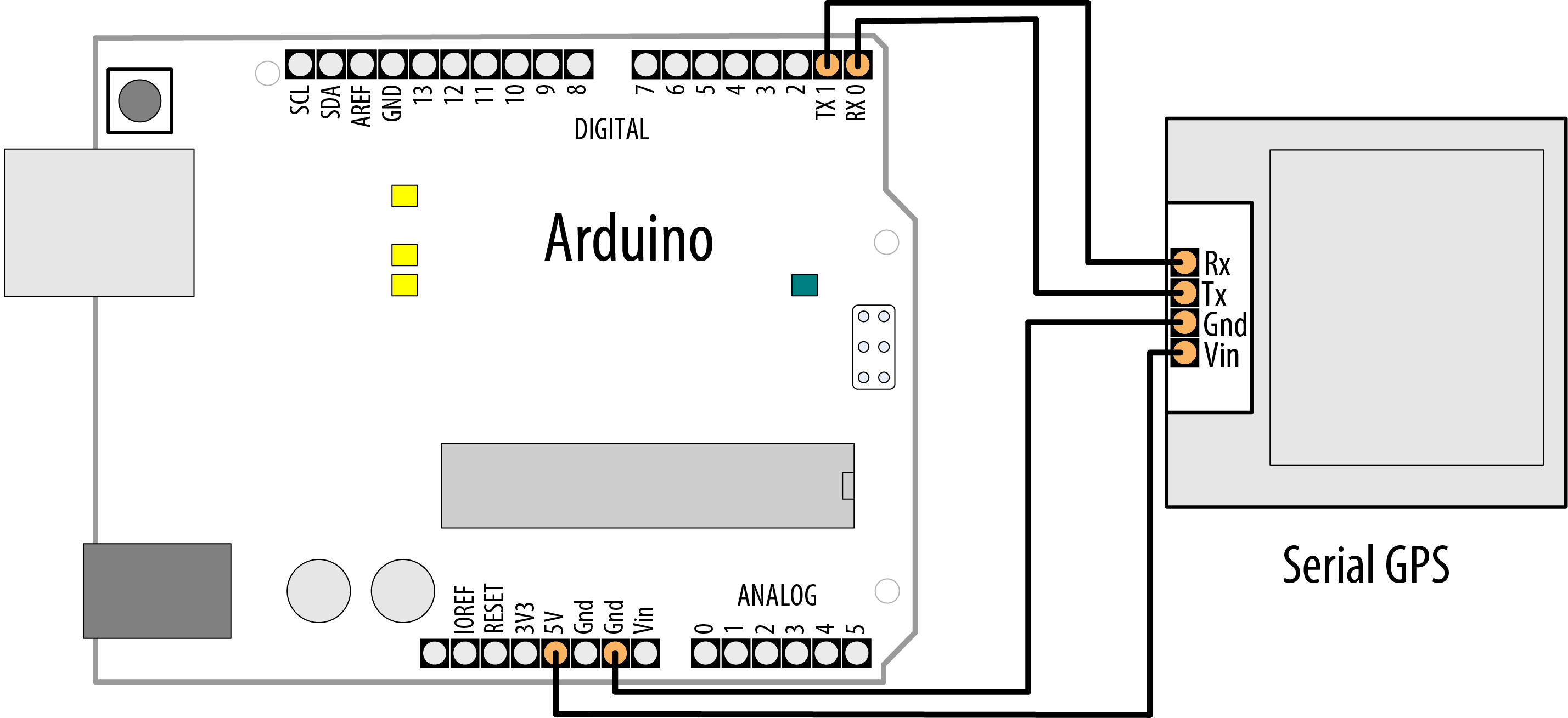
Connecting a serial device to a built-in serial port’s receive pin
Warning
If you are using an Arduino or Arduino-compatible board that operates at 5V (such as an Uno), you can safely receive data from a device that uses 3.3V. But if you are using a board that operates at 3.3V (most ARM-based boards) with a device that uses 5V logic levels, you will eventually damage your board unless you incorporate a voltage divider into the circuit to bring the voltage down. See Recipe 4.13 and Recipe 5.11 for examples of voltage dividers.
On the Arduino Uno and other boards based on the ATmega328, which has only one hardware serial port, you will need to create an emulated or “soft” serial port using the SoftwareSerial library. You will be limited to slower transfer speeds than with a built-in hardware serial port.
This problem is similar to the one in Recipe 4.11, and indeed the solution is much the same. If your Arduino’s serial port is connected to the console and you want to attach a second serial device, you must create an emulated port using a software serial library. In this case, we will be receiving data from the emulated port instead of writing to it, but the basic solution is very similar.
Select two pins to use as your transmit and receive lines. This Solution uses pins 8 and 9 because some boards (such as the Arduino Leonardo) can only support SoftwareSerial receive on pins 8, 9, 10, 11, and 14. These also happen to be among the pins that the Arduino Mega and Mega 2560 support for SoftwareSerial receive. In practice, you would probably use the hardware serial available on pins 0 and 1 (Serial1) on these boards (the Mega boards have pins that support hardware serial as Serial2 and Serial 3). But we chose SoftwareSerial pins that would work on the widest possible range of boards in case you decide to test this code on one of them.
Connect your GPS as shown in Figure 4-8.

Connecting a serial GPS device to a “soft” serial port
As you did in Recipe 4.11, create a SoftwareSerial object in your sketch and tell it which pins to control. In the following example, we define a soft serial port called serial_gps, using pins 8 and 9 for receive and transmit, respectively. Even though we’re not going to be sending any data to this serial device, we need to specify a transmit pin, so you shouldn’t use pin 9 for anything else when you are using the SoftwareSerial port
Note
To use the following code with a built-in hardware serial port, connect the pins as shown in Figure 4-7, then remove these lines:
#include <SoftwareSerial.h>
const int rxpin = 8;
const int txpin = 9;
SoftwareSerial serial_gps(rxpin, txpin);
Finally, add this line in their place (change Serial1 if you are using a different port):
#define serial_gps Serial1
/*
 * SoftwareSerialInput sketch
 * Read data from a software serial port
 */

#include <SoftwareSerial.h>
const int rxpin = 8;                     // pin used to receive from GPS
const int txpin = 9;                     // pin used to send to GPS
SoftwareSerial serial_gps(rxpin, txpin); // new serial port on these pins

void setup()
{
  Serial.begin(9600); // 9600 baud for the built-in serial port
  serial_gps.begin(9600); // initialize the port, most GPS devices
                          // use 9600 bits per second
}

void loop()
{
  if (serial_gps.available() > 0) // any character arrived yet?
  {
    char c = serial_gps.read();   // if so, read it from the GPS
    Serial.write(c);              // and echo it to the serial console
  }
}
This short sketch simply forwards all incoming data from the GPS to the Arduino Serial Monitor. If the GPS is functioning and your wiring is correct, you should see GPS data displayed on the Serial Monitor.
Discussion
You initialize an emulated SoftwareSerial port by providing pin numbers for transmit and receive. The following code will set up the port to receive on pin 8 and send on pin 9:
const int rxpin = 8;                     // pin used to receive from GPS
const int txpin = 9;                     // pin used to send to GPS
SoftwareSerial serial_gps(rxpin, txpin); // new serial port on these pins
The syntax for reading an emulated port is very similar to that for reading from a built-in port. First check to make sure a character has arrived from the GPS with available(), and then read it with read().
It’s important to remember that software serial ports consume time and resources. An emulated serial port must do everything that a hardware port does, using the same processor your sketch is trying to do “real work” with. Whenever a new character arrives, the processor must interrupt whatever it is doing to handle it. This can be time-consuming. At 4,800 baud, for example, it takes the Arduino about two milliseconds to process a single character. While two milliseconds may not sound like much, consider that if your connected device transmits 200 to 250 characters per second, your sketch is spending 40 to 50 percent of its time trying to keep up with the serial input. This leaves very little time to actually process all that data. The lesson is that if you have two serial devices, when possible connect the one with the higher bandwidth consumption to the built-in (hardware) port. If you must connect a high-bandwidth device to a software serial port, make sure the rest of your sketch’s loop is very efficient.
Receiving data from multiple SoftwareSerial ports
With the SoftwareSerial library included with Arduino, it is possible to create multiple “soft” serial ports in the same sketch. This is a useful way to control, say, several XBee radios (see Recipe 14.2) or serial displays in the same project. The caveat is that at any given time, only one of these ports can actively receive data. Reliable communication on a software port requires the processor’s undivided attention. That’s why SoftwareSerial can only actively communicate with one port at a given time.
It is possible to receive on two different SoftwareSerial ports in the same sketch. You just have to take some care that you aren’t trying to receive from both simultaneously. There are many successful designs which, say, monitor a serial GPS device for a while, then later accept input from an XBee. The key is to alternate slowly between them, switching to a second device only when a transmission from the first is complete.
For example, in the sketch that follows, an XBee module is connected to the Arduino. The module is receiving commands from a remote device connected to another XBee module. The sketch listens to the command stream through the “xbee” port until it receives the signal to begin gathering data from a GPS module attached to a second SoftwareSerial port. The sketch then monitors the GPS for 10 seconds—hopefully long enough to establish a “fix”—before returning to the XBee.
In a system with multiple “soft” ports, only one is actively receiving data. By default, the “active” port is the one for which begin() has been called most recently. However, you can change which port is active by calling its listen() method. listen() instructs the SoftwareSerial system to stop receiving data on one port and begin listening for data on another.
The following code fragment illustrates how you might design a sketch to read first from one port and then another:
Note
Because this example is only receiving data, you can choose any pins for txpin1 and txpin2. If you need to use pins 9 and 11 for something else, you can change txpin1/2 to another pin. We recommend against changing it to a nonexistent pin number, because that could lead to some unusual behavior.
/*
 * MultiRX sketch
 * Receive data from two software serial ports
 */
#include <SoftwareSerial.h>
const int rxpin1 = 8;
const int txpin1 = 9;
const int rxpin2 = 10;
const int txpin2 = 11;

SoftwareSerial gps(rxpin1, txpin1);  // gps TX pin connected to Arduino pin 9
SoftwareSerial xbee(rxpin2, txpin2); // xbee TX pin connected to pins Arduino pin 10

void setup()
{
  Serial.begin(9600);
  xbee.begin(9600);
  gps.begin(9600);
  xbee.listen(); // Set “xbee” to be the active device
}

void loop()
{
  if (xbee.available() > 0) // xbee is active. Any characters available?
  {
    if (xbee.read() == 'y') // if xbee received a 'y' character?
    {
      gps.listen(); // now start listening to the gps device

      unsigned long start = millis(); // begin listening to the GPS
      while (start + 100000 > millis())
      // listen for 10 seconds
      {
        if (gps.available() > 0) // now gps device is active
        {
          char c = gps.read();
          Serial.write(c);              // echo it to the serial console
        }
      }
      xbee.listen(); // After 10 seconds, go back to listening to the xbee
    }
  }
}
This sketch is designed to treat the XBee radio as the active port until it receives a y character, at which point the GPS becomes the active listening device. After processing GPS data for 10 seconds, the sketch resumes listening on the XBee port. Data that arrives on an inactive port is simply discarded.
Note that the “active port” restriction only applies to multiple soft ports. If your design really must receive data from more than one serial device simultaneously, consider using a board, such as the Teensy (http://www.pjrc.com/teensy), that supports several serial ports (the Teensy 4.0 supports seven in total). Table 4-1 shows the pins used for Serial ports on various Arduino and Arduino-compatible boards.
See Also
If you would like to go further with a GPS and parse the messages that you receive, see Recipe 6.14. For an alternative to SoftwareSerial that can support multiple devices more robustly, see the AltSoftSerial library.
4.13 Using Arduino with the Raspberry Pi
Problem
You want to use Arduino capabilities together with the processing power of a single-board Linux computer such as Raspberry Pi. For example, you want to send commands to Arduino from a script running on the Pi.
Solution
Arduino can monitor and respond to serial commands from the Raspberry Pi. The code here controls Arduino LEDs from Python scripts running on Pi.
Connect the Arduino serial receive pin (pin 0 marked RX on the board) to pin 8 on the Pi’s header pins). Connect Arduino TX pin 1 to the Pi GPIO pin 10). The Arduino ground (GND) pin connects to any of the Pi ground pins (pin 14 is used here).

Arduino board connected to Raspberry Pi
Note
It is also possible to connect Arduino to a Raspberry Pi using one of the Raspberry Pi’s USB ports. In fact, you can even run the Arduino IDE on the Raspberry Pi. Download one of the ARM versions from https://www.arduino.cc/en/main/software. At the time of this writing, the Raspberry Pi operating system, Raspbian, operated in 32-bit mode, so you’d choose the 32-bit version unless you’re running a 64-bit operating system.
Here is an Arduino sketch that monitors serial messages from the Pi. Upload this to the Arduino board.
Note
The sketch shown is for the Arduino Uno and any Arduino compatible that has a single serial port shared between the USB serial connection and the RX/TX pins. If you are using a board with an additional hardware serial port, such as the Leonardo, WiFi Rev2, Nano Every, or any ARM-based board, change #define mySerial Serial to #define mySerial Serial and if your board doesn’t use pins 0 and 1 for RX and TX, use the appropriate pins for Serial1 (see Table 4-1).
/** ArduinoPi sketch* Pi control Arduino pins using serial messages* format is: Pn=state* where 'P' is header character, n is pin number, state is 0 or 1* example: P13=1 turns on pin 13*/// Replace Serial with Serial1 on boards with an additional serial port#define mySerial Serialvoidsetup(){mySerial.begin(9600);// Initialize serial port to send/receive at 9600 baud}voidloop(){if(mySerial.available())// Check whether at least one character is available{charch=mySerial.read();intpin=-1;if(ch=='P')// is this the beginning of a message to set a pin?{pin=mySerial.parseInt();// get the pin number}elseif(ch=='B')// Message to set LED_BUILTIN{pin=LED_BUILTIN;}if(pin>1){// 0 and 1 are usually serial pins (leave them alone)intstate=mySerial.parseInt();// 0 is off, 1 is onpinMode(pin,OUTPUT);digitalWrite(pin,state);}}}
Save the following Python script as blinkArduino.py on the Pi, and run it with python blinkArduino.py. The script will blink the onboard LED on the Arduino board. You must have the python-serial library installed before you run it. You can install it on the Raspberry Pi with sudo apt-get install python-serial.
#!/usr/bin/env pythonimportserialfromtimeimportsleepser=serial.Serial('/dev/serial0',9600)ser.write('P13=1')sleep(1)ser.write('P13=0')
When the script is run, an LED on pin 13 should turn on for one second and then go off.
Discussion
The Arduino sketch detects the start of a message when the character ‘P’ is received. The Arduino parseInt function is used to extract the desired pin number and pin state. Sending P13=1 will turn on the LED on Pin 13. P13=0 will turn the LED off. More information on Serial messages and parseInt can be found in Chapter 4. Many Arduino and Arduino-compatible boards use some pin other than 13, so to save you the trouble of having to look that up, the Arduino sketch will use the LED_BUILTIN constant as the pin number when you send it a message like B=1 (no pin number required).
The Python script sends the appropriate messages to turn the LED on then off.
If your board’s builtin LED is not on pin 13, use this version, which uses the B command to toggle whichever LED is assigned to LED_BUILTIN:
#!/usr/bin/env pythonimportserialfromtimeimportsleepser=serial.Serial('/dev/serial0',9600)ser.write('B=1')sleep(1)ser.write('B=0')
Raspberry Pi pins are not 5 volt-tolerant, so you must use the voltage divider shown in the diagram if you are connecting a 5V Arduino-compatible board to the Pi. If you are using a 3.3V Arduino, it’s generally safe to omit the voltage divider, but the voltage divider won’t hurt it. See Recipe 5.11 for more details on voltage dividers.
The messages sent in this recipe are very simple but can be expanded to enable the Pi to control over almost any Arduino function and for Arduino to send information back to the Pi. See Chapter 4 for more on getting Arduino working with a computer over the serial link.
Details on Python and the Pi can be found online and in books such as ‘The Raspberry Pi Cookbook’.