Chapter 21. VXLAN
Virtual eXtensible Local Area Network (VXLAN) is a technology that allows devices to communicate on the same Layer 2 (L2) network, even if they are separated by Layer 3 (L3) boundaries. To overly simplify, it’s like tunneling L2 over L3, but it’s not that easy, because if they made it simple, we wouldn’t have jobs.
Networking people have been taught for decades to cut up L2 broadcast domains as much as possible to limit the potential damage caused by things like broadcast storms. Additionally, as data centers grew in size, we began running up against limits in the switch hardware such as the maximum number of MAC addresses supported. To that end, we have insisted that data centers have their own IP space. I made a lot of money back in the 90s moving companies off of massive bridged environments and moving them to more logical, segmented IP solutions. So why the step backward?
Solutions such as vMotion allow virtual machines (VMs) to be moved from host to host while keeping the machine available for use. That’s a pretty cool thing to do, but to pull it off, the IP address of the VM needs to stay the same. Having data centers in multiple locations is a good thing for disaster avoidance, so those hosts might be in different physical locations. Thus, we have a need for the same IP space to exist in two different physical locations.
Additionally, some clustering technology requires all of the hosts to be within the same IP space. It’s common for companies to want to cluster between multiple buildings for resiliency, which again leads us to the requirement for having the same L2 domain in different buildings.
As a long-time network architect, I have spent a fair amount of time rebelling against this. I have some very smart friends who are VMware and storage guys, and they consider me the reason why they can’t get their work done. When the network guys insist on a design that prevents the server/storage/VM guys from getting their solutions implemented, the network guys become the roadblock.
The answer (that guys like me really dislike) is that the network exists to serve the connection needs of the servers. If there were no servers, there would be no networks. Because the network hasn’t really evolved to meet the needs of modern virtual computing and modern virtual computing keeps insisting on using L2 networks for its solutions, we are stuck trying to make it all work.
There are a couple of existing technologies out there today that try to solve this problem. Cisco’s Overlay Transport Virtualization (OTV) uses a network device to tunnel L2 through L3, but it is designed as a point-to-point solution like a network virtual private network (VPN) might be deployed. Because of this, no additional configuration is required on the servers, hosts, or VMware clusters. OTV is Cisco proprietary and requires either a Cisco Nexus switch (a Virtual Device Context [VDC] can be dedicated to OTV) or a Cisco ASR router to function as the OTV devices.
VXLAN is an open standard that was developed with multiple vendors including Cisco, VMware, Arista, and others. Ken Duda, one of Arista’s founders, had a major part in its creation.
VXLAN, like most things in IT, is rife with new terms, acronyms, and initialisms, so let’s define those before we move on.
- VXLAN Overlay Network (Segment)
VXLAN provides an L2 overlay network that exists on top of an L3 network. Yes, that would be L2 tunneled over L3, which is over L2. Each one of the L2 networks is called a VXLAN Overlay Network or VXLAN Segment. These segments are discrete (there can be many) and are identified by their VXLAN Network Identifiers.
- VXLAN Network Identifier (VNI)
-
The VNI is the means whereby VXLAN keeps the L2 overlay networks separated. It is also sometimes called the VXLAN Segment-ID. The VNI is akin to a VLAN number, but there can be many more VNIs than there can be VLANs on a traditional switch given that the VNI is a 24-bit value (16,777,216 possibilities), whereas the VLAN ID is only a 12-bit value (4,096).
Only hosts on the same VNI can communicate with one another. Hosts are identified by a combination of the host’s MAC address and the VNI. Because of this, the same MAC address can appear on multiple VNIs.
- VXLAN Tunnel End Point (VTEP)
-
VTEPs are the devices that encapsulate and tear down VXLAN packets. VTEPs can be part of a hypervisor, but they can also be in separate networking hardware, in which case they are called a VXLAN Gateway.
- VXLAN Gateway
-
A VXLAN Gateway is a device outside of a hypervisor that allows non-VXLAN-compliant devices to communicate over VXLAN Overlay Networks. Another term you might see for this is Hardware VTEP.
Two additional terms that are thrown around a lot when talking about VXLAN are underlay and overlay. When we build a VXLAN environment, we’re often overlaying an L2 network on top of an existing L3 network. That L3 network is the underlying architecture or underlay network, whereas the VXLAN network on top of it is considered to be the overlay network.
VXLAN has many facets including VXLAN-bridging and VXLAN routing. In this chapter, I focus on VXLAN bridging because my goal is for you to understand the technology in an efficient amount of space. I can’t cover everything, so I’ve focused on the basic functionality of VXLAN bridging.
Understanding VXLAN
I like to say that VXLAN is nothing more than a VLAN with an X in the middle. What it does is connect VLANs (technically L2 segments) separated by L3 networks. All of the stuff that we’ll talk about is the X—it’s the technical details that people like us need to know, but in the end it’s connecting two (or more) VLANs together, and after you understand how it does that, you’ll see that it will behave like…wait for it…a VLAN.
Note
Note that Arista’s implementation of VXLAN is hardware based and, as such, might not be supported on every Arista switch or software-only devices (VEOS-lab, etc.).
Imagine a company with two data centers connected via an IP cloud. It doesn’t matter what the IP cloud consists of. That’s why it’s a cloud. As an aside, it amazes me how many people don’t know that cloud means I don’t know (and I don’t care) what’s in there. Anyway, because of demands outside of the network team’s control (cough VMware cough), the order has been passed down that the servers in one data center must be able to communicate with servers in the other data center as if they were in the same L2 network. You know, like a VPN only without all that encryption and security stuff.
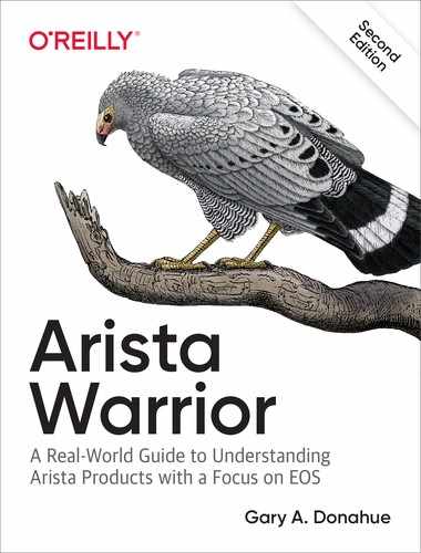
In our imaginary company, DC-1 is built using the network 11.0.0.0/8, and DC-2 is built using the network 12.0.0.0/8. The network that needs to exist simultaneously within both is 10.0.0.0/24 and happens to be contained with VLAN 100 on both sides. Figure 21-1 shows this network.
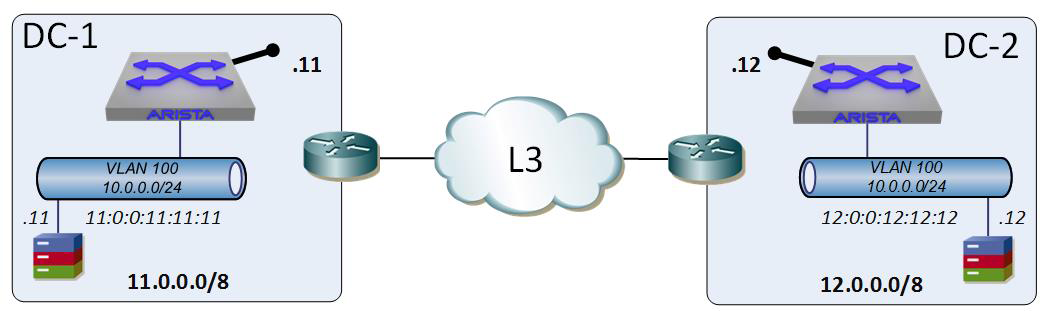
Figure 21-1. Two data centers, both having the same 10.0.0.0/24 networks within them
Because there are multiple L3 networks separating the two VLAN 100 networks, how might we connect them? A VPN between them would work, but this requires specialty hardware due to the encryption that we don’t really need. We could build a Generic Routing Encapsulation (GRE) tunnel between them, and that would probably work in this scenario. Heck, there are a bunch of solutions that might work, so let’s make it more like the real world in which things are never that simple.
In Figure 21-2 we have the exact same scenario, only now there’s a third data center that uses 13.0.0.0/8 while also having the 10.0.0.0/24 network in a VLAN 100. Suddenly, point-to-point solutions don’t scale quite as well because we have two destinations that both have the same network (10.0.0.0/24), so we now need to consider things like multipoint solutions.
Figure 21-2. Three data centers with the same 10.0.0.0/24 networks
Back when the Cisco Nexus 7000s were new, Cisco released OTV. By putting a Nexus 7000 at the border, you could sort of grab VLAN traffic and tunnel it to another location, thus providing the solution desired (one VLAN in three L3-separated data centers). I looked at OTV when it was young and the problems were many. First, it required Nexus 7000s (it is now supported on other devices) and required a Virtual Device Context (VDC) to work. What’s worse is that it supported only 256 VLANs, so if you needed more, you had to burn another VDC. At the time, I was working for a client that had more than 700 VLANs (and growing) in a multitenancy environment, and when we exceeded the number of VDCs available in the Nexus 7000s (four at the time), the answer from Cisco was to deploy another set of Nexus 7000s just for OTV. My response at the time was simple: nope!
The way that OTV solves the problem at hand is through what Arista calls Data Center Interconnect or DCI. In other words, the VLANs in the data center need to go through a common choke-point where everything is encapsulated, sent to the other side, and then decapsulated. The entire data center is interconnected—hence the name. VXLAN doesn’t really work this way (though it can with some clever design work).
In our imaginary company, you no doubt noticed the huge Arista switches in each data center. Note that these are not edge devices, but are within the data centers. These Arista switches are the switches that have VLAN 100 configured on them, so what if we could form a tunnel from them? That’s exactly how we will deploy VXLAN, as shown in Figure 21-3.
Instead of an expensive edge device working to capture and encapsulate everything, these devices are encapsulating only what’s necessary and only on the configured VLANs. Certainly, OTV works only on the configured VLANs, but I consider it (and most DCI solutions) to be more of a blunt weapon solution, whereas VXLAN is more targeted and refined. There can be problems with that, so don’t think I’m saying that it’s all rainbows and unicorns, but we’ll get there in due time.
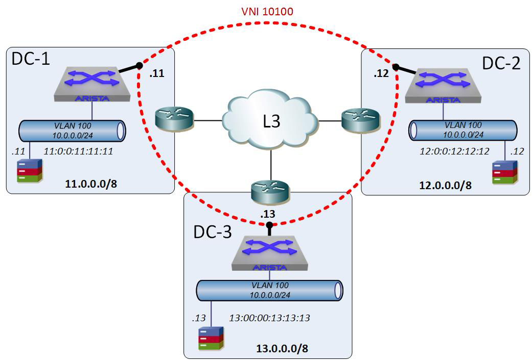
Figure 21-3. VXLAN tunnels
The thing to remember about VXLAN is that it’s dynamic. The tunnels (which aren’t really tunnels in the strictest sense of the word, as you’ll see) come and go as needed, sort of like an on-demand VPN but much simpler and without any perceptible delay.
Note
VXLAN is an encapsulation technology. The head-end VTEP takes an L2 frame, wraps it in an L3 packet, and then forwards it to another VTEP. The target VTEP then removes the L3 encapsulation and forwards it as a regular L2 frame. The reason I don’t call this a tunnel is because there isn’t really a tunnel interface that needs to be up for this to work. Perhaps a better statement would be that VXLAN does not use stateful tunnels like, for example, GRE.
I should point out that VXLAN does not need to be configured on a switch; it could be implemented directly on the VMware ESXi server itself. In my mind, this makes a lot of sense, but in my experience, server teams don’t always do network designs very well, and the idea of server teams making hundreds if not thousands of tunnels all across the network in random, unforeseen, and likely unsupported ways keeps me up at night. Plus, this is an Arista book, so I focus on the Arista solution.
Let’s review some terms now that we have a pretty picture in Figure 21-3 to look at. Those dotted lines are each a VXLAN Overlay Network or VXLAN Segment. The interfaces that they are connected to at each end are VXLAN Interfaces on the Arista switches (we see how to configure them in the next section). The Arista switch that contains the VXLAN Interface is the endpoint for the VXLAN Segments and is therefore called a VXLAN Tunnel End-Point or VTEP. To transition to VXLAN-speak, we now have three VXLAN Segments that terminate at three VTEPs.
To understand how all of this really works, I need to shift gears for a moment. Imagine now, a simple switch with a single VLAN. The VLAN has six interfaces, as shown in Figure 21-4.
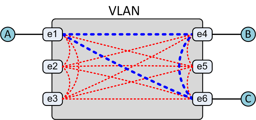
Figure 21-4. Switch VLAN traffic flow
A switch is a switch because there is a dedicated path from every interface to every other interface and each path is only used when needed. This interconnected mesh of paths is called the switch’s fabric. In Figure 21-4, if host A wants to talk to host B over IP but doesn’t know host B’s MAC address, what happens? As soon as the destination is determined to be on the same network via a simple subnet mask XOR operation, a broadcast is sent in the form of an Address Resolution Protocol (ARP) request to every port except the one on which it originated. Who has the IP address of B?
This L2 broadcast is received on every connected port, and the host who has that IP address responds via unicast to A. After this happens, the switch knows (because it’s been listening to the conversations) where A and B are, and when A sends a packet to B’s MAC address, only the proper path is used. When the network is running and stable, the only paths that will be used for A, B, and C to communicate are the bold paths. This is the way switches have worked since there have been switches, and you know what? This is the exact same way that VXLAN works.
Consider now the exact same environment, only instead of a switch fabric and a VLAN connecting hosts, we now have an L3 cloud that’s connecting VTEPs, as shown in Figure 21-5.
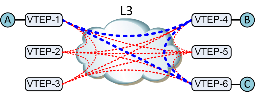
Figure 21-5. VXLAN traffic flow
If host A wants to talk to host B on the same network but doesn’t know its MAC address, it sends a broadcast. The same thing happens on the local switch (VTEP-1), but now VXLAN is in the mix, and VXLAN is connecting the VLAN across the L3 cloud.
VXLAN knows the IP addresses of all of the other VTEPs (we see how in a bit) and, just like on a switch sending a broadcast to all interfaces except the one on which it was received, sends the broadcast to all known VTEPs. But how do you send an L2 broadcast across an L3 network? You don’t.
What might you use to have the same packet received at multiple different points across multiple L3 networks? Multicast! Only we’re not going to do that. Why not? Even though it is supported these days, there are a variety of reasons including things like security, quality of service (QoS) concerns, and some other things that make multicast not the best choice, so we’re going to use something else called Head-End Replication (HER).
Note
Advanced VXLAN configurations include topics such as VXLAN with Multichassis Link Aggregation (MLAG) and routing over VXLAN, neither of which work with multicast and therefore must use HER or Ethernet VPN (EVPN).
HER simulates a broadcast by replicating the packet being sent at the head end (hence the name). In other words, if host A sends an ARP request broadcast, VTEP-1 will take that frame, encapsulate it into an L3 packet, replicate it, and send a copy to each of the known VTEPs. The receiving VTEPs will decapsulate the packet and forward the L2 frame as if it were locally originated. When the correct host receives it, it will respond as a unicast, which will then go back across the proper VXLAN Segment (VTEP-4 to VTEP-1) and be decapsulated by VTEP-1. After this happens, each of the VTEPs at either end update their tables so that they don’t need to go through the HER broadcast step again. This behavior is the same as a switch updating its mac-address-table, only on a larger scale because it could conceivably be happening on scores of switches miles apart.
HER is done any time a broadcast, an unknown unicast, or a multicast packet needs to traverse the VXLAN network. This traffic is called BUM traffic, and no, I didn’t make that up.
This is perhaps the toughest thing for people to grasp when it comes to VXLAN, but think of each VTEP as an interface in a VLAN with the VLAN being the L3 cloud and you’ll see that it’s the same thing. Let’s go back to our imagined corporate network and apply what we’ve learned.
Each VTEP will have an IP address that the other VTEPs will reference, so that IP address must be routable to the other VTEPs. This is the VXLAN interface, and this is where the VXLAN Segments will terminate. In our corporate network the VTEPs are at 11.0.0.11, 12.0.0.12, and 13.0.0.13.
VTEPs know about other VTEPs through something called the flood-list. We can manually configure this (which we see in a bit), which is fine for smaller networks, but think of the fact that every VTEP needs to know the address of every other VTEP and the VLAN/VTI associated with it. If you have 100 VTEPs, the flood-list for every one of them needs to contain the IP address of every other VTEP. That is an administrative nightmare and a recipe for human error, so Arista has come up with a solution using its CloudVision product: CloudVision eXchange, or CVX. CVX dynamically learns the remote VTEP addresses (and associated VXLAN-Enabled L2 segments) and updates the flood-lists for you. I explain how that works later in the chapter, but for right now I’ll use a small-scale example and manually configure it.
Another thing that I haven’t explained yet is the fact that each VXLAN network is identified by a VNI. Think of the VNI as a VLAN number because that’s kind of what it is but with a couple of very important distinctions.
First, whereas a VLAN is identified with a 12-bit number, the VNI is 24-bits, which means that there can be 16,777,216 possibilities. Because a VLAN is mapped to a VNI, VNIs are a great solution for multitenancy because you can map the same VLAN number used by different customers into a different VNI numbers, thus segregating their traffic.
In Figure 21-6, I’ve added a VNI number and the flood-lists for each VTEP. VLANs are mapped to VNIs, and in this case, I’ve mapped VLAN 100 to VNI 10100. I often design solutions in which maybe the first two digits are the customer number and the last three are the VLAN, though perhaps four and four digits would scale better. In this example, customer 10’s VLAN 100 has been mapped to VNI 10100.
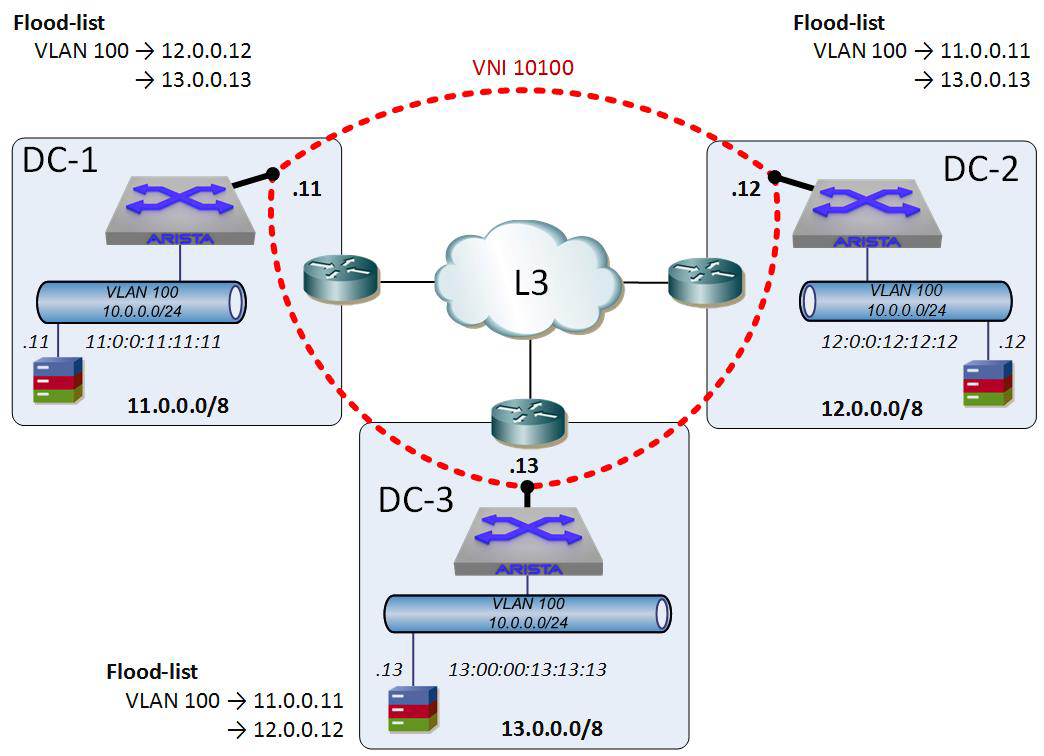
Figure 21-6. VXLAN VNIs and flood-lists
With the flood-lists in place, each of the VTEPs now knows where each of the other VTEPs can be reached. Note that this does not mean that broadcasts are unnecessary, because a flood-list does not mean that a host behind the VTEP knows how to get to a host behind another VTEP. Think of the flood-list as the way in which you’d create a VLAN and then add interfaces to it in a switch. The flood-list shows each VTEP where the other VTEPs (ports, if you will) are. That’s all.
After the VTEPs and flood-lists are in place, the network can begin behaving as we’d expect and as devices start communicating across our VLAN-with-an-X-in-the-middle (VXLAN) network, the VXLAN address-tables begin to populate. These are analogous to a switch’s mac-address-table, only instead of a MAC address being behind an interface, the MAC address is behind an IP address (a VTEP), as shown in Figure 21-7.
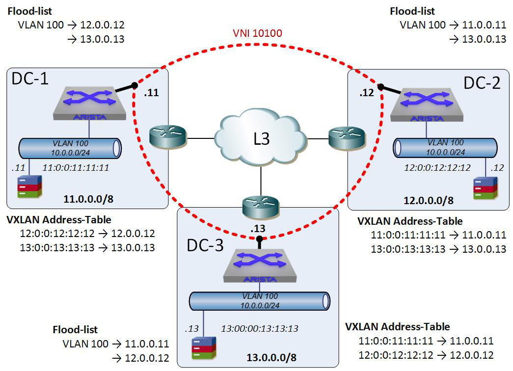
Figure 21-7. VXLAN-address-tables added to our network
With all of this in place, the entire VXLAN environment behaves like a giant switch in which each VTEP is an interface. If the host 10.0.0.11 wants to talk to the host 10.0.0.12, the local switch knows that it’s in the VXLAN address-table and encapsulates the frame and forwards it to the VTEP at 12.0.0.12. That VTEP decapsulates the packet and forwards the frame to the proper device.
Configuring VXLAN
Believe it or not, understanding VXLAN is much more difficult than configuring it, at least at the scale we’re talking about here. It can be quite complicated in larger environments depending on how you configure the control-plane.
Two of my least-favorite terms in networking are control-plane and data-plane, but in the interest of not getting a thousand emails from angry nerds (it wouldn’t be the first time!) I’ll save that rant for another time.
Note
I am the king of the angry nerds, so I totally get it. I’m also the king of strong opinions, even if they’re not always popular in the industry. Basically, I’m a king with many crowns, including the one for banging angry chapter notes into my laptop while sitting alone in Starbucks.
Here’s how the terms are used in VXLAN:
- Control-plane
- The means whereby VTEPs know or learn about other VTEPs. This is essentially the configuration (be it manual or dynamic) of the flood-lists, VLAN-VNI mappings, and anything having to do with VTEP learning.
- Data-plane
- The actual encapsulation/decapsulation of L2 frames into L3 packets and the subsequent forwarding of encapsulated packets to remote VTEPs.
There are three major ways in which a VXLAN control plane is configured, which I describe as manual, CVX, and routing protocol. Before we look at those, let’s take a look at the network I’ll be using to explain them. To simulate the network I’ve shown earlier in this chapter, I’ve created the layout presented in Figure 21-8.
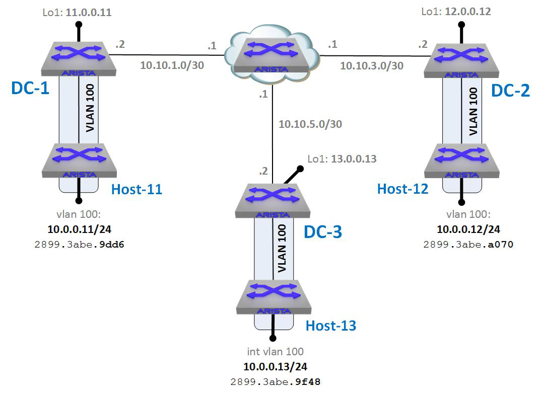
Figure 21-8. VXLAN lab layout
The layout is pretty much the same, with DC1, DC2, and DC3 being simulated with Arista switches named as such. The hosts in each data center are named Host-11, Host-12, and Host-13 accordingly. Looking at the drawing, you can see that each host and data center contains a VLAN 100, which is local to that data center. Each host has an SVI for VLAN 100 with a 10.0.0.x/24 IP address that associates with the data center in which it is located. Host-11 has the IP address of 10.0.0.11, Host-12 has the IP address of 10.0.0.12, and Host-13 has the IP address of 10.0.0.13. Note that these VLANs are local to each of the data centers, and, as such, they cannot directly communicate with each other because the data centers are separated by L3 routing. That routing happens to be Border Gateway Protocol (BGP) in the lab, but that is essentially irrelevant in these examples (though it can help to explain some of the output we’ll see).
Given this layout, trying to ping host 10.0.0.12 or 10.0.0.13 from 10.0.0.11 fails:
Host-11#ping 10.0.0.12
PING 10.0.0.12 (10.0.0.12) 72(100) bytes of data.

--- 10.0.0.12 ping statistics ---
5 packets transmitted, 0 received, 100% packet loss, time 4004ms

Host-11#ping 10.0.0.13
PING 10.0.0.13 (10.0.0.13) 72(100) bytes of data.

--- 10.0.0.13 ping statistics ---
5 packets transmitted, 0 received, 100% packet loss, time 4004ms
This makes perfect sense due to the fact that the L2 VLANs in each data center are not connected at L2 to the other data centers. We can fix that with VXLAN.
Figure 21-9 presents the same drawing with the VXLAN Segments shown to help you to visualize what we’re trying to accomplish.

Figure 21-9. VXLAN lab with VXLAN Segments shown
How we accomplish this will vary depending on the control-plane methodology in use, so let’s look at them individually.
VXLAN with Manual Control-Plane
Though arguably the simplest of the methods, manually configuring VTEPs and flood-lists does not scale well due mostly to the fact that someone needs to keep track of the VTEPs in the network and manually update all of the other VTEPs. That’s not a big deal in our lab where there are only three VTEPs, but in a dynamic or large environment, that task would quickly become unbearable. Still, I like it because it helps to get people to understand how VXLAN works.
First, I need to point out that all IP routing is already in place and that the VLANs and port configurations are already correct, so I do not cover them here (to save space).
To get VXLAN to work, we first must configure a VXLAN interface.
DC-1(config)#interface Vxlan1
DC-1(config-if-Vx1)#
To make VXLAN as resilient as possible, we use the source-interface of Loopback-1 (lo1). In a real network, this would be beneficial with multiple paths being available to the switch. In our lab, that’s not the case, but you need to use a source-interface regardless of how your network is built.
DC-1(config-if-Vx1)#vxlan source-interface loopback 1
Next, we need to map the VLAN to a VNI:
DC-1(config-if-Vx1)#vxlan vlan 100 vni 10100
The VNI is a number between 1 and 16,777,215, although if you’d prefer a more IP-address-looking format, you can configure EOS to accept dotted-decimal notation by using the vxlan vni notation dotted global command:
DC-1(config-if-Vx1)#vxlan vni notation dotted
DC-1(config)#
With dotted-decimal notation, VNIs use the format of 0.0.1 to 255.255.255. Let’s see what happened to our VNI after we changed this:
DC-1(config)#int vxlan 1
DC-1(config-if-Vx1)#sho active
interface Vxlan1
   vxlan source-interface Loopback1
   vxlan udp-port 4789
   vxlan vlan 100 vni 0.39.116
Cool, huh? Maybe not the way I did it, but if you’d rather see a VNI of 0.10.100, this is how you would go about it:
DC-1(config-if-Vx1)#vxlan vlan 100 vni 0.10.100
DC-1(config-if-Vx1)#sho active
interface Vxlan1
   vxlan source-interface Loopback1
   vxlan udp-port 4789
   vxlan vlan 100 vni 0.10.100
I’m not a huge fan of that format, so let’s change it back.
DC-1(config-if-Vx1)#no vxlan vni notation dotted
DC-1(config)#int vxlan 1
DC-1(config-if-Vx1)#sho active
interface Vxlan1
   vxlan source-interface Loopback1
   vxlan udp-port 4789
   vxlan vlan 100 vni 2660
Ugh—let’s fix that:
DC-1(config-if-Vx1)#vxlan vlan 100 vni 10100
DC-1(config-if-Vx1)#sho active
interface Vxlan1
   vxlan source-interface Loopback1
   vxlan udp-port 4789
   vxlan vlan 100 vni 10100
That’s better. I hope that I don’t need to point out that 10100 and 0.10.100 are not the same value, especially after I just showed that they aren’t.
Finally, we need to configure the flood lists. EOS actually allows for per-VLAN flood-lists and a default flood-list. To configure a default flood-list, don’t specify a VLAN:
DC-1(config-if-Vx1)#vxlan flood vtep 12.0.0.12 13.0.0.13
As you can see, I added both remote VTEPs on one line. I can also do it like this:
DC-1(config-if-Vx1)#vxlan flood vtep 12.0.0.12
DC-1(config-if-Vx1)#vxlan flood vtep add 13.0.0.13
Don’t forget the add keyword! Otherwise, you’ll end up overwriting the first entry:
DC-1(config-if-Vx1)#vxlan flood vtep 12.0.0.12
DC-1(config-if-Vx1)#sho active
interface Vxlan1
   vxlan source-interface Loopback1
   vxlan udp-port 4789
   vxlan vlan 100 vni 10100
   vxlan flood vtep 12.0.0.12
DC-1(config-if-Vx1)#vxlan flood vtep 13.0.0.13
DC-1(config-if-Vx1)#sho active
interface Vxlan1
   vxlan source-interface Loopback1
   vxlan udp-port 4789
   vxlan vlan 100 vni 10100
   vxlan flood vtep 13.0.0.13
Let’s fix that:
DC-1(config-if-Vx1)#vxlan flood vtep 12.0.0.12 13.0.0.13
DC-1(config-if-Vx1)#sho active
interface Vxlan1
   vxlan source-interface Loopback1
   vxlan udp-port 4789
   vxlan vlan 100 vni 10100
   vxlan flood vtep 12.0.0.12 13.0.0.13
By the way, you might have noticed the addition of the vxlan udp-port 4789 command even though we didn’t add it. This is a configurable option, but because the default port is 4789, EOS adds the command for you to ensure that it works.
I mentioned that there are two ways to manually configure flood-lists, and we just completed the default flood-list method. To configure a flood-list for a VLAN, simply add the VLAN to the command as follows:
DC-1(config-if-Vx1)#vxlan vlan 100 flood vtep 12.0.0.12 13.0.0.13
This command works similarly to the default syntax in that you can add VTEPs on a single line or add them like this:
DC-1(config-if-Vx1)#vxlan vlan 100 flood vtep 12.0.0.12
DC-1(config-if-Vx1)#vxlan vlan 100 flood vtep add 13.0.0.13
The results of either method will now show the following configuration:
DC-1(config-if-Vx1)#sho active
interface Vxlan1
   vxlan source-interface Loopback1
   vxlan udp-port 4789
   vxlan vlan 100 vni 10100
   vxlan flood vtep 12.0.0.12 13.0.0.13
   vxlan vlan 100 flood vtep 12.0.0.12 13.0.0.13
This is not really something you’d see in the real world (assuming a rational configuration), so let’s change the default flood-list to something else:
DC-1(config-if-Vx1)#vxlan flood vtep 99.0.0.99
DC-1(config-if-Vx1)#sho active
interface Vxlan1
   vxlan source-interface Loopback1
   vxlan udp-port 4789
   vxlan vlan 100 vni 10100
   vxlan flood vtep 99.0.0.99
   vxlan vlan 100 flood vtep 12.0.0.12 13.0.0.13
Why do this? It could be that all of your VLANs are using the same VTEPs, so you don’t need a per-VLAN scheme. It could be that all of your VLANS except for one use the same VTEPs, so all other VLANs use the default flood-list, whereas specific VLANs use something else. It’s all about options and the ability to consolidate the configuration where possible. To show how this might look, let me add a VLAN-VNI map for VLAN 200:
DC-1(config-if-Vx1)#vxlan vlan 200 vni 99200
Now I have VLAN 100, which is mapped to VNI 10100, and VLAN 200, which is mapped to VNI 99200. I’ve set up a specific flood-list for VLAN 100, but all other VLANs that have VNI maps use the default:
DC-1(config-if-Vx1)#sho active
interface Vxlan1
   vxlan source-interface Loopback1
   vxlan udp-port 4789
   vxlan vlan 100 vni 10100
   vxlan vlan 200 vni 99200
   vxlan flood vtep 99.0.0.99
   vxlan vlan 100 flood vtep 12.0.0.12 13.0.0.13
The way to see the flood-lists is by using the show vxlan flood vtep command:
DC-1(config-if-Vx1)#sho vxlan flood vtep
          VXLAN Flood VTEP Table
----------------------------------------------------------------

VLANS                            Ip Address
-----------------------------   --------------------------------
100                             12.0.0.12       13.0.0.13
200 *                           99.0.0.99
*  All VLANs in the indicated VLAN range list are using the
   default VTEP flood list
Removing the VLAN 200 map and the default flood-list, here’s the configuration for all three of the data center switches from my lab:
DC-1
DC-1#sho run sec vxlan
interface Vxlan1
   vxlan source-interface Loopback1
   vxlan udp-port 4789
   vxlan vlan 100 vni 10100
   vxlan vlan 100 flood vtep 12.0.0.12 13.0.0.13
DC2
DC-2#sho run sec vxlan
interface Vxlan1
   vxlan source-interface Loopback1
   vxlan udp-port 4789
   vxlan vlan 100 vni 10100
   vxlan vlan 100 flood vtep 11.0.0.11 13.0.0.13
DC3
DC-3#sho run sec vxlan
interface Vxlan1
   vxlan source-interface Loopback1
   vxlan udp-port 4789
   vxlan vlan 100 vni 10100
   vxlan vlan 100 flood vtep 11.0.0.11 12.0.0.12
As a reminder, Figure 21-10 illustrates the layout of the lab.
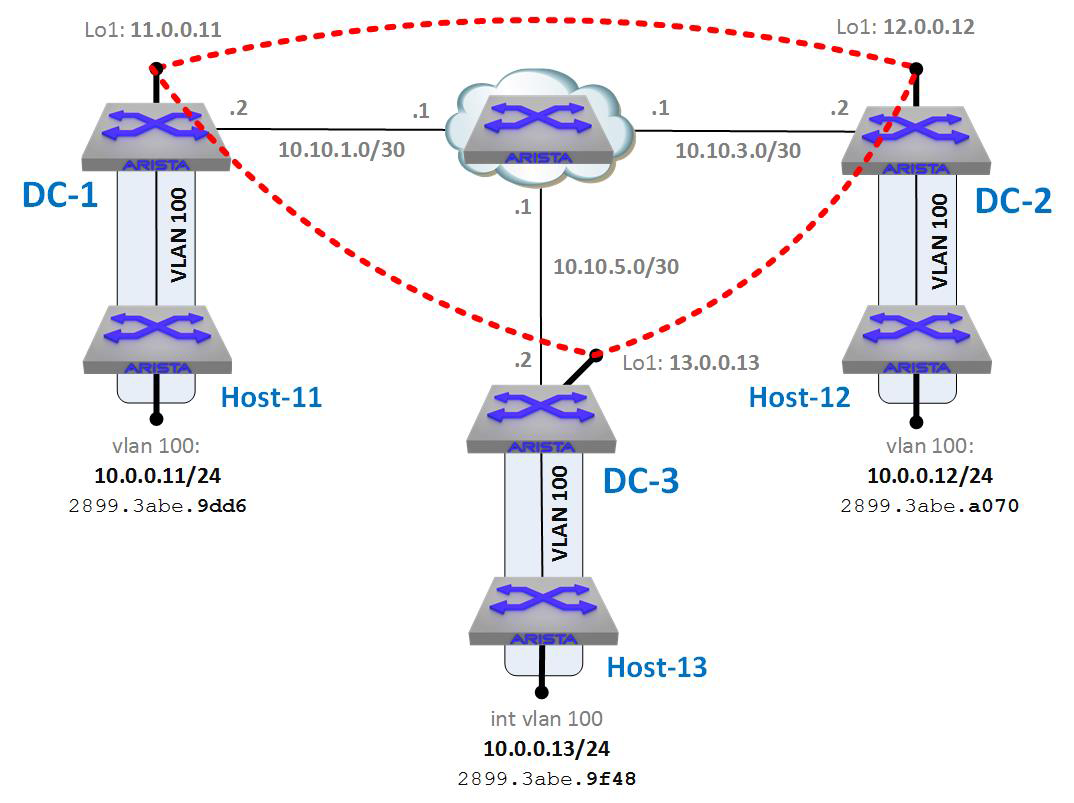
Figure 21-10. VXLAN lab with VXLAN Segments
With the VXLAN interfaces on all three data center switches configured, let’s try to ping from Host-11 to Host-12 again:
Host-11(vrf:11)#ping 10.0.0.12
PING 10.0.0.12 (10.0.0.12) 72(100) bytes of data.
80 bytes from 10.0.0.12: icmp_seq=1 ttl=64 time=0.263 ms
80 bytes from 10.0.0.12: icmp_seq=2 ttl=64 time=0.113 ms
80 bytes from 10.0.0.12: icmp_seq=3 ttl=64 time=0.104 ms
80 bytes from 10.0.0.12: icmp_seq=4 ttl=64 time=0.109 ms
80 bytes from 10.0.0.12: icmp_seq=5 ttl=64 time=0.109 ms

--- 10.0.0.12 ping statistics ---
5 packets transmitted, 5 received, 0% packet loss, time 0ms
rtt min/avg/max/mdev = 0.104/0.139/0.263/0.063 ms, ipg/ewma 0.236/0.199 ms
From DC1, we can see what VTEPs have been used recently with the show vxlan vtep command:
DC-1#sho vxlan vtep
Remote VTEPS for Vxlan1:
12.0.0.12
Total number of remote VTEPS:  1
Nice! How about pinging from Host-11 to Host-13?
Host-11(vrf:11)#ping 10.0.0.13
PING 10.0.0.13 (10.0.0.13) 72(100) bytes of data.
80 bytes from 10.0.0.13: icmp_seq=1 ttl=64 time=0.255 ms
80 bytes from 10.0.0.13: icmp_seq=2 ttl=64 time=0.104 ms
80 bytes from 10.0.0.13: icmp_seq=3 ttl=64 time=0.105 ms
80 bytes from 10.0.0.13: icmp_seq=4 ttl=64 time=0.100 ms
80 bytes from 10.0.0.13: icmp_seq=5 ttl=64 time=0.097 ms

--- 10.0.0.13 ping statistics ---
5 packets transmitted, 5 received, 0% packet loss, time 0ms
rtt min/avg/max/mdev = 0.097/0.132/0.255/0.061 ms, ipg/ewma 0.201/0.191 ms
Beautiful! Again, from DC1, we can see what VTEPs have been used recently by using the show vxlan vtep command:
DC-1#sho vxlan vtep
Remote VTEPS for Vxlan1:
12.0.0.12
13.0.0.13
Total number of remote VTEPS:  2
Be aware that this output will be empty unless traffic has been sent to the remote VTEP, and the status times out after about five minutes. This is not a status of the tunnel (because it’s not a stateful tunnel); rather (according to the documentation), it displays the VTEPs that have exchanged data with the configured VTI. Note also that though I pinged from Host-11, I got the VXLAN VTEP status from DC-1 because Host-11 has no idea that VXLAN even exists.
How about the mac-address-table for VXLAN? You can see this by using the show vxlan address-table command. This is similar to the switch’s show mac address-table command, but instead of a MAC address being found behind an interface, it’s found behind an IP address that represents a remote VTEP:
DC-1#sho vxlan address-table
          Vxlan Mac Address Table
--------------------------------------------------------------------

VLAN  Mac Address     Type     Prt  VTEP           Moves   Last Move
----  -----------     ----     ---  ----           -----   ---------
 100  2899.3abe.9f48  DYNAMIC  Vx1  13.0.0.13      1       0:00:02 ago
 100  2899.3abe.a070  DYNAMIC  Vx1  12.0.0.12      1       0:03:21 ago
Total Remote Mac Addresses for this criterion: 2
If you look at the MAC addresses and compare them to the drawing in Figure 21-10, you’ll see how the MAC addresses are found behind the IP address of the VTEP that connects them to the VXLAN Segments.
Another troubleshooting tool at your disposal is the show vxlan vni command, which can help to show more information about how VNIs have been mapped:
DC-1#sho vxlan vni
VNI to VLAN Mapping for Vxlan1
VNI         VLAN       Source       Interface        802.1Q Tag
----------- ---------- ------------ ---------------- ----------
10100       100        static       Ethernet48       untagged

Note: * indicates a Dynamic VLAN
Although the ability to manually configure VXLAN is tempting for such a small and stable environment as the one in my lab, larger and more complex environments usually rely on some sort of dynamic means for VTEP and flood-list learning. The simplest of those choices, in my opinion, is Arista’s own CVX.
VXLAN with CVX
With CVX in the mix, the CVX server (a vEOS instance) handles all of the heavy lifting for things like VTEP discovery, thus alleviating the need for statically configured flood-lists. This employs something called the VXLAN Control Service on CVX, the end result being that the control-plane for VXLAN becomes completely automated.
Consider our original diagram with CVX added, as shown in Figure 21-11. Each of the data center switches subscribes to the CVX server, which then acts as a controller for VXLAN. In this scenario CVX handles all of the control-plane needs for the VTEPs.
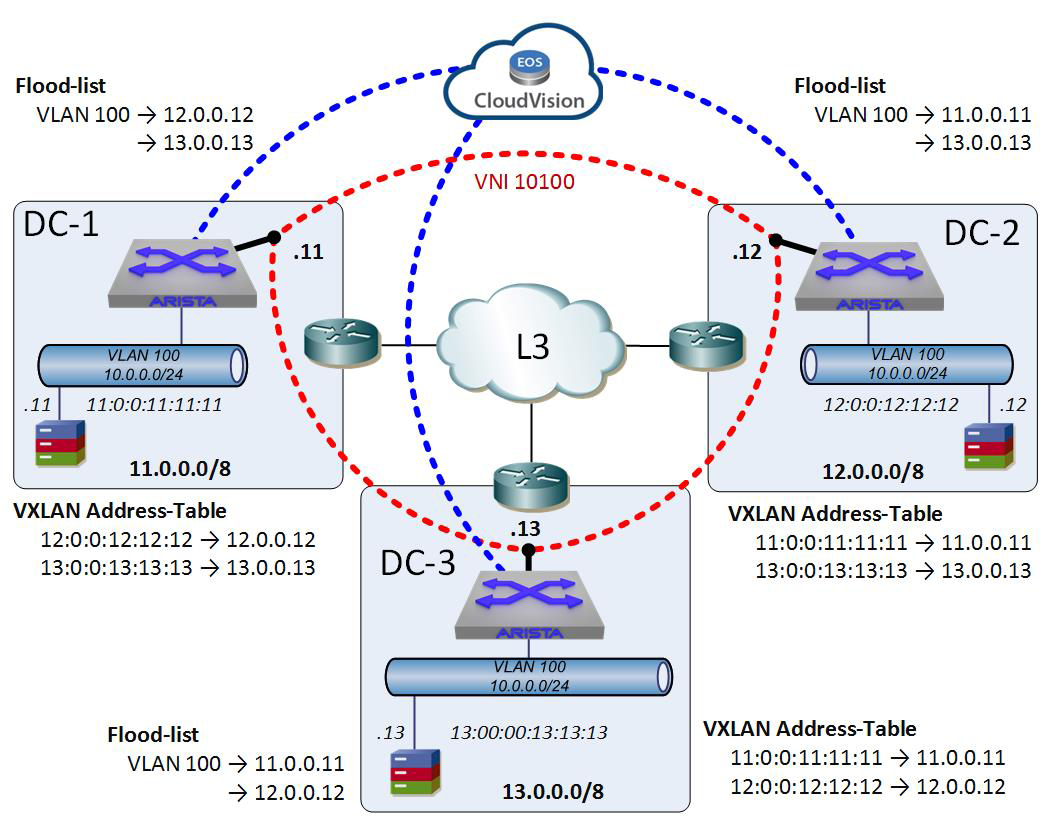
Figure 21-11. VXLAN with CVX
CVX is nothing more than a vEOS VM in this situation, which once again shows the power of vEOS (Chapter 32).
First, here’s the configuration of the CVX instance as it relates to our lab:
cvx
   no shutdown
   source-interface loopback 1
!
   service vxlan
      no shutdown

hostname CVX

interface Loopback0
   ip address 99.0.0.99/32
There is some routing involved to get Loopback0 into the routing tables of the other switches, but let’s not pollute the chapter with that. For my lab network, this is all of the configuration that’s necessary (aside from the aforementioned routing) to get CVX working as a VXLAN controller. In fact, it will work without the source-interface command and just using the management interface’s IP address, but best practice is to have a loopback with multiple paths to it if possible.
On the VTEPs (the data center switches in this lab), the only thing that’s required is the following:
DC-1(config)#management cvx
DC-1(config-mgmt-cvx)#no shut
DC-1(config-mgmt-cvx)#server host 99.0.0.99
We also need to instruct VXLAN that it’s running in client mode by using the vxlan controller-client command in the VXLAN interface configuration:
DC-1(config)#int vxlan 1
DC-1(config-if-Vx1)#vxlan controller-client
That’s it! Well, that’s it in addition to the normal VXLAN stuff, so let’s take a look at the entire thing from the point of view of DC1:
DC-1#sho run section vxlan
interface Vxlan1
   vxlan source-interface Loopback1
   vxlan controller-client
   vxlan udp-port 4789
   vxlan vlan 100 vni 10100
Note that there is no configuration of a remote VTEP. Here’s the configuration for CVX:
DC-1#sho run section cvx
management cvx
   no shutdown
   server host 99.0.0.99
To see whether the CVX connection is working, use the show vxlan controller status command:
DC-1#sho vxlan controller status
Controller connection status        : Established
Resync in progress after CVX reboot : No
Purge in progress after CVX reboot  : No
Status: Enabled
You can also use the show management cvx status command for more detail:
DC-1#sho management cvx
CVX Client
Source interface: Inactive (Not configured)
  VRF: default
  Heartbeat interval: 20.0
  Heartbeat timeout: 60.0
  Controller cluster name: default
    Controller status for 99.0.0.99
      Master since 0:15:19 ago
      Connection status: established
      Connection timestamp: 0:15:19 ago
        Out-of-band connection: Not secured
        In-band connection: Not secured (SSL not supported)
      Negotiated version: 2
      Controller UUID: f59be14e-15d9-11e9-bf41-525400230eb3
      Last heartbeat sent: 0:00:19 ago
      Last heartbeat received: 0:00:19 ago
The magic word for the connection status is established. If it says anything else, it’s probably not working, and if it’s not working, it’s probably something simple because there’s not a lot that can go wrong, in my experience, provided you’re running all of the VTEPs and the CVX controller on the same (or at least very similar) versions of EOS.
To see the status of the CVX controller in regard to VXLAN, use the show cvx service Vxlan command, being careful to note that the V in Vxlan is a capital letter:
CVX(config-cvx)#sho cvx service Vxlan
Vxlan
  Status: Enabled
  Supported versions: 2

  Switch            Status  Negotiated Version
  ----------------- ------- ------------------
  28:99:3a:be:9e:20 Enabled 2
  28:99:3a:be:9f:92 Enabled 2
  28:99:3a:be:a1:04 Enabled 2
If this upsets your “but EOS is not case sensitive!” sensibilities, Vxlan is not a keyword, but rather a service name, and the name of the service is Vxlan, just like the name of the agent that runs spanning-tree is Stp with a capital S.
There is a pile of other useful commands in CVX, such as show cvx connections, which shows the VTEPs in our lab because we’re using only the Vxlan service in this environment:
CVX(config-cvx)#sho cvx connections
Switch 28:99:3a:be:a1:04
  Hostname: DC-3
  State: established
  Connection timestamp: 0:21:07 ago
  Last heartbeat sent: 0:00:07 ago
  Last heartbeat received: 0:00:07 ago
  Out-of-band connection: Not secured
  In-band connection: Not secured (SSL not supported)
Switch 28:99:3a:be:9e:20
  Hostname: DC-2
  State: established
  Connection timestamp: 0:21:07 ago
  Last heartbeat sent: 0:00:07 ago
  Last heartbeat received: 0:00:07 ago
  Out-of-band connection: Not secured
  In-band connection: Not secured (SSL not supported)
Switch 28:99:3a:be:9f:92
  Hostname: Arista
  State: established
  Connection timestamp: 0:21:07 ago
  Last heartbeat sent: 0:00:07 ago
  Last heartbeat received: 0:00:07 ago
  Out-of-band connection: Not secured
  In-band connection: Not secured (SSL not supported)
With CVX running, let’s take a look at the flood-lists on the data center switches. Here’s DC1:
DC-1#sho vxlan flood vtep
          VXLAN Flood VTEP Table
------------------------------------------------------------------

VLANS                    Ip Address
----------------------   ------------------------------------------
100                      11.0.0.11       12.0.0.12       13.0.0.13
Remember we have not configured any flood-lists, so this list was completely learned via CVX. Here’s the output of the same command from DC2:
DC-2#sho vxlan flood vtep
          VXLAN Flood VTEP Table
------------------------------------------------------------------

VLANS                    Ip Address
----------------------   ------------------------------------------
100                      11.0.0.11       12.0.0.12       13.0.0.13
And, finally, from DC3:
DC-3#sho vxlan flood vtep
          VXLAN Flood VTEP Table
------------------------------------------------------------------

VLANS                    Ip Address
----------------------   ------------------------------------------
100                      11.0.0.11       12.0.0.12       13.0.0.13
I find it interesting that the flood-list for each of the VTEPs includes itself and upon digging a bit deeper learned that VTEPs in the flood-list containing local addresses are ignored. This makes sense to me because it would allow CVX to send the same flood-list to every VTEP that needs it (in this case, those with the same VNI mapped to VLAN 100).
Another very cool feature of using CVX is that the VXLAN address table is synchronized between all of the VTEPs automatically. To demonstrate this, using a newly rebooted lab as shown earlier, let’s ping Host-12 from Host-11. In this scenario DC3 is not involved at all, but watch what happens:
Host-11#ping 10.0.0.12
PING 10.0.0.12 (10.0.0.12) 72(100) bytes of data.
80 bytes from 10.0.0.12: icmp_seq=1 ttl=64 time=0.245 ms
80 bytes from 10.0.0.12: icmp_seq=2 ttl=64 time=0.100 ms
80 bytes from 10.0.0.12: icmp_seq=3 ttl=64 time=0.100 ms
80 bytes from 10.0.0.12: icmp_seq=4 ttl=64 time=0.106 ms
80 bytes from 10.0.0.12: icmp_seq=5 ttl=64 time=0.102 ms

--- 10.0.0.12 ping statistics ---
5 packets transmitted, 5 received, 0% packet loss, time 0ms
rtt min/avg/max/mdev = 0.100/0.130/0.245/0.058 ms, ipg/ewma 0.204/0.186 ms
With the ping having been forwarded from Host-11 to DC1, through the VNI to DC2, and then on to Host-12, DC3 is not involved at all, but check out what happens immediately on the DC3 VTEP:
DC-3#sho vxlan address-table
          Vxlan Mac Address Table
-------------------------------------------------------------------

VLAN  Mac Address     Type     Prt  VTEP          Moves   Last Move
----  -----------     ----     ---  ----          -----   ---------
 100  2899.3abe.9dd6  RECEIVED  Vx1  11.0.0.11     1    0:00:02 ago
 100  2899.3abe.a070  RECEIVED  Vx1  12.0.0.12     1    0:00:02 ago
Total Remote Mac Addresses for this criterion: 2
Even though DC3 had nothing to do with the forwarding of the frame from Host11 (MAC ending in 9dd6) to Host12 (MAC ending in a070), the learned MAC address of both along with the VTEPs where they were discovered have been updated and populated to all of the VTEPs that CVX knows should get the information. That may seem to be a trivial benefit in this small network, but consider the fact that should a host behind DC3’s VTEP need to get to either of these hosts, the VTEP already knows about the destination MAC address and the VTEP to send to without having to send a broadcast (via HER) to every VTEP in the flood-list. This can make the entire environment significantly more efficient, especially in larger environments.
VXLAN with EVPN
Even though CVX is amazingly easy to set up and use (customers have told me that it was the best thing that Arista has ever written), it is an Arista feature and, as such, not supported by other vendors. In a multivendor environment, the solution for discovery of VTEPs is often the open protocol EVPN, which is an address extension of the protocol BGP.
The downside of EVPN is that it’s fairly complicated and takes up a lot of configuration space. When I asked around for a deck about EVPN, I was given a 500-plus slide collection, which, by the way, was quite well done. The problem is that 500 slides is more than enough for me to teach a three-day class. After trying in vain for days to try and come up with a way to explain and demonstrate a simple solution for this book, I came to the conclusion that this was not the book for such an example because I could easily consume an additional 30 pages just explaining the way it all works without even getting into VXLAN-specific examples. Although I’m not averse to adding another 30 or more pages, doing so makes the physical book larger and thus makes the price go up. This edition is already larger than the first edition, and so I had to make the difficult decision to not include EVPN.
As a matter of fact, the verbose nature of EVPN has been one of the drivers I’ve seen that’s pushed customers into automation solutions like CloudVision because it can make the command-line interface (CLI) configuration unwieldy in even smaller environments.
VXLAN with MLAG
VXLAN with MLAG is a bit more complicated than it might seem on the surface, and that’s because for VXLAN to be involved, it means that there’s an L3 path to the MLAG pair, and this means that we’re dealing with a mixed L2/L3 environment. To show how an MLAG pair might be used with MLAG, I’ve added a new data center to our lab environment called DC4, as depicted in Figure 21-12.
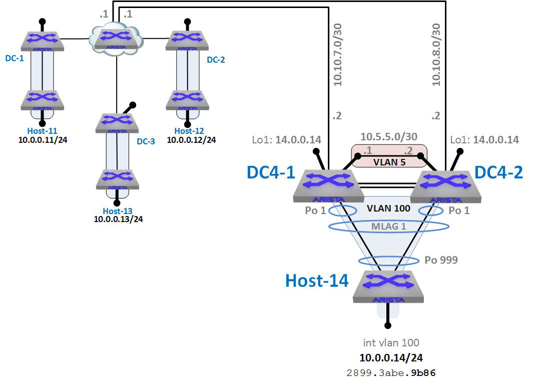
Figure 21-12. MLAG added to our VXLAN lab
Remember that the cloud in the center of our lab is L3, so we need to have an L3 connection to our new DC4. To do this, we have an L3 link to each of the switches in the MLAG pair. Thus, DC4 is L3 into the cloud, but L2 (using MLAG) down to Host-14.
Because we’re using L3, we need an L3 link between the MLAG peers in case one of those L3 links goes down. That interswitch L3 link is VLAN 5 with the IP network of 10.5.5.0/30. More details on configuring such a solution is available in Chapter 18.
The trick for making this design work with VXLAN is that the loopback interfaces on each of the MLAG peers have the same IP address, which in this case is 14.0.0.14. With VXLAN configured to use this interface as the source-interface, and with both switches in the MLAG domain having the same VLAN-VNI mapping and flood-lists, the MLAG pair will behave as a single logical VTEP. Really, that’s it! So long as the routing is properly set up and MLAG is properly configured, having the VXLAN information configured the same way on both switches in the domain will make it work. Let’s look at the configurations. Here is the relevant configuration for DC4-1:
hostname DC4-1
!
no spanning-tree vlan 4094
!
vlan 5,100
!
vlan 4094
   trunk group mlagpeer
!
interface Port-Channel1
   description [ Host-14 MLAG ]
   switchport access vlan 100
   mlag 1
!
interface Port-Channel1000
   description [ MLAG Peer-Link ]
   switchport mode trunk
   switchport trunk group mlagpeer
!
interface Ethernet31
   description [ BGP Link to Cloud ]
   no switchport
   ip address 10.10.7.2/30
!
interface Ethernet33
   description [ Host-14 ]
   channel-group 1 mode active
!
interface Ethernet47
   description [ MLAG Peer ]
   channel-group 1000 mode active
!
interface Ethernet48
   description [ MLAG Peer ]
   channel-group 1000 mode active
!
interface Loopback1
   ip address 14.0.0.14/8
!
interface Vlan5
   description [ BGP ISL ]
   no autostate
   ip address 10.5.5.1/30
!
interface Vlan4094
   description [ MLAG Link ]
   no autostate
   ip address 10.255.255.1/30
!
interface Vxlan1
   vxlan source-interface Loopback1
   vxlan controller-client
   vxlan udp-port 4789
   vxlan vlan 100 vni 10100
!
ip routing
!
mlag configuration
   domain-id mlag
   local-interface Vlan4094
   peer-address 10.255.255.2
   peer-link Port-Channel1000
!
router bgp 65007
   maximum-paths 32 ecmp 32
   neighbor 10.5.5.2 remote-as 65008
   neighbor 10.5.5.2 maximum-routes 12000
   neighbor 10.10.7.1 remote-as 65100
   neighbor 10.10.7.1 maximum-routes 12000
   neighbor 10.10.7.5 remote-as 65100
   neighbor 10.10.7.5 maximum-routes 12000
   network 10.1.7.0/24
   network 14.0.0.0/8
!
management cvx
   no shutdown
   server host 99.0.0.99
Although there is a lot of added code in relation to MLAG and BGP, if you look at the VXLAN configuration (in bold), you can see that it’s really very similar to what we’ve done in the other data centers. Note the loopback IP address, which is 14.0.0.14/8. You’ll see the exact same loopback address in DC14. Here is the relevant configuration for DC14-2, with the VXLAN config again in bold:
hostname DC4-2
!
vlan 5,100
!
vlan 4094
   trunk group mlagpeer
!
interface Port-Channel1
   description [ Host-14 MLAG ]
   switchport access vlan 100
   mlag 1
!
interface Port-Channel1000
   description [ MLAG Peer-Link ]
   switchport mode trunk
   switchport trunk group mlagpeer
!
interface Ethernet31
   description [ BGP Link to Cloud ]
   no switchport
   ip address 10.10.8.2/30
!
interface Ethernet32
   no switchport
   ip address 10.10.8.6/30
!
interface Ethernet33
   description [ Host-14 ]
   channel-group 1 mode active
!
interface Ethernet47
   description [ MLAG Peer ]
   channel-group 1000 mode active
!
interface Ethernet48
   description [ MLAG Peer ]
   channel-group 1000 mode active
!
interface Loopback1
   ip address 14.0.0.14/8
!
interface Vlan5
   description [ BGP ISL ]
   no autostate
   ip address 10.5.5.2/30
!
interface Vlan4094
   description [ MLAG Link ]
   no autostate
   ip address 10.255.255.2/30
!
interface Vxlan1
   vxlan source-interface Loopback1
   vxlan controller-client
   vxlan udp-port 4789
   vxlan vlan 100 vni 10100
!
ip routing
!
mlag configuration
   domain-id mlag
   local-interface Vlan4094
   peer-address 10.255.255.1
   peer-link Port-Channel1000
!
router bgp 65008
   maximum-paths 32 ecmp 32
   neighbor 10.5.5.1 remote-as 65007
   neighbor 10.5.5.1 maximum-routes 12000
   neighbor 10.10.8.1 remote-as 65100
   neighbor 10.10.8.1 maximum-routes 12000
   neighbor 10.10.8.5 remote-as 65100
   neighbor 10.10.8.5 maximum-routes 12000
   network 10.1.8.0/24
   network 14.0.0.0/8
!
management cvx
   no shutdown
   server host 99.0.0.99
To prove that this is behaving as I’ve described, I first show the VXLAN flood-lists, which have been populated to each VTEP from CVX given that this is what we’re still using for the control-plane.
Here is DC1’s VXLAN flood-list:
DC-1#sho vxlan flood vtep
          VXLAN Flood VTEP Table
-----------------------------------------------------------------------

VLANS                            Ip Address
-----------------------------   ---------------------------------------
100                             11.0.0.11    12.0.0.12    13.0.0.13
                                14.0.0.14
We can see here that so far as DC1 (and CVX and every other VTEP in the mix) is concerned, there is a VTEP at IP address 14.0.0.14, which is the IP we configured on loopback-1 of both of the DC4 MLAG peers. Here’s what the same table looks like on DC14-1:
DC4-1#sho vxlan flood vtep
          VXLAN Flood VTEP Table
-----------------------------------------------------------------------

VLANS                            Ip Address
-----------------------------   ---------------------------------------
100                             11.0.0.11    12.0.0.12    13.0.0.13
                                14.0.0.14
This shouldn’t really be a surprise because CVX is populating these tables, and they should therefore all be the same. As a result of the MLAG pair appearing as a single logical VTEP in the L3 network and as a single logical bridge in the L2 network, Figure 21-13 shows how this design appears logically.
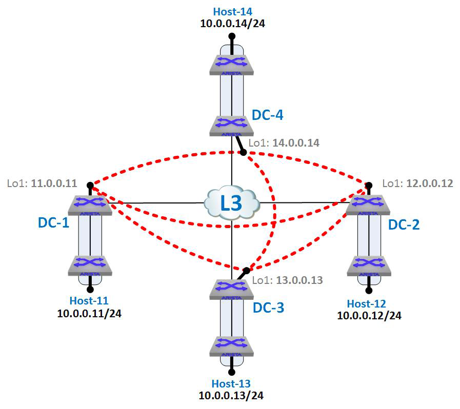
Figure 21-13. VXLAN with DC4 as seen logically
Note that DC4 is a single VTEP and there is really no obvious appearance of MLAG, which is kind of the point of MLAG in the first place. The fact that it can work as a logical VTEP makes it even cooler, though.
I’ve also added dotted lines that show the VXLAN Segments as they can exist given the VLAN-VNI mappings and distributed flood-lists. Because CVX is distributing the flood-lists and they’re all the same, the VTEPs have become fully meshed and any of the hosts on the 10.0.0.x network can ping any of the other hosts in any of the data centers, even though they’re separated by L3 networks and even though one of the data centers is using an L2 MLAG design internally.
How does the VXLAN-configured MLAG pair handle a failure, though? Actually, it’s really not that exciting and works exactly the way you’d expect. Here’s a short list of possibilities:
- Upstream link failure
- BGP routes over VLAN 5 to the other peer and uses the other link
- MLAG peer failure
- Normal Link Aggregation Control Protocol rehashing takes care of L2 paths, whereas BGP continues to route accordingly upstream
In our configured network a complex failure could bring DC4 down, and by complex failure I mean the upstream link from DC4-1 fails while DC4-2 peer also fails. That would put DC4 offline, which is why the upstream should be a four-way Equal-Cost MultiPathing link, but now we’re getting deeper into the resiliency aspect of network design, which is not really what this chapter is for.
Conclusion
There are myriad other advanced topics relating to VXLAN that I’m not going to cover here. This chapter is one of the largest in the book already (and that’s without EVPN!), so topics such as L3 routing with VXLAN, VXLAN pseudo-wire for virtual data centers, data-center interconnect, and a bunch of other buzzword-heavy topics have not been included. Because this book is aimed primarily at the new Arista user and the second edition is already getting too large, such advanced topics are for another venue.
VXLAN is a powerful tool that can solve problems that traditional networking simply cannot. Even though there are certainly other similar solutions out there that claim to do the same thing, VXLAN as an open standard seems to be where the industry has chosen to go.