
Multichassis Link Aggregation (MLAG), is the Arista term for linking a port-channel to multiple switches instead of just one. The technology accomplishes the same basic goal as Cisco’s Virtual Port Channel (vPC); although, in my experience, MLAG is simpler to configure and less likely to fail in colorful, job-threatening ways.
The term LAG is an abbreviation for Link Aggregation, which is a non-Cisco way of describing the bonding of multiple physical links into a single logical link. In Cisco parlance, this technology is called Etherchannel. Different vendors use different terms for similar solutions, but the term LAG has become a cross-vendor acceptable way of describing the idea.
A LAG connects multiple physical links on the same switch. MLAG is designed to allow two or more links on multiple switches into a single logical link. Why would you want to do this? Let’s take a look.
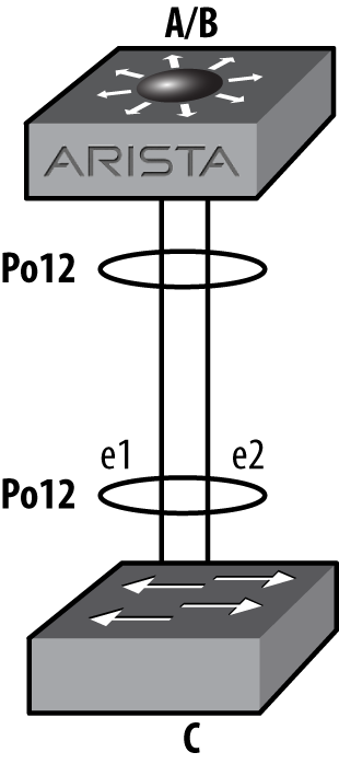
With a traditional network design, interconnecting three switches results in a loop. Loops are bad, so Spanning Tree Protocol (STP) blocks the interface on the link farthest from the root. An example of this is shown in Figure 12-1.
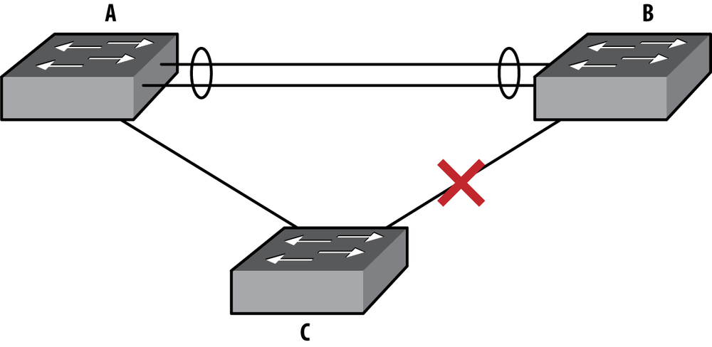
In this scenario, there is a LAG connecting switch A to switch B. Switch C connects to both A and B switches, forming a loop. STP has blocked the interface on switch C that leads to switch B in order to break said loop. This design will allow for failover if the link between switches A and C were to fail, but the failover can take 30 seconds or more (substantially less if rapid STP is used). Not only that, but only one half of the available bandwidth too and from switch C is available for use. Wouldn’t it be cool if we could use that extra link? Even better, if we used LAG technology, then a single link failure wouldn’t incur an outage because the second link would already be active.
With MLAG, two Arista switches fool the third switch (or any other dot1Q-capable device) into thinking that it is talking with a single device. In other words, two Arista switches appear to be one Arista switch to dot1Q. This is shown in Figure 12-2.
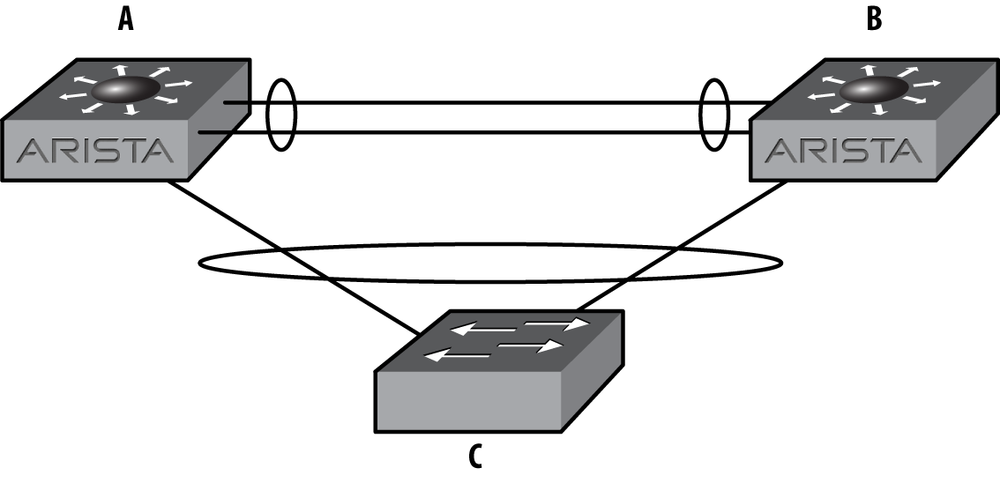
With MLAG active, switch C sees a 20 Gbps logical interface, to a single device, even though it is connected to two devices. Arista accomplishes this feat by advertising the same device ID from both switch A and switch B. In order to do this, switch A and switch B must communicate over the A–B switch link, which must be configured with a VLAN that acts as a peer-link.
MLAG is configured within something called an MLAG Domain. The MLAG Domain ID identifies the switch to another switch that will share MLAGs. Multiple MLAG domains must be used when interconnecting MLAGs between MLAG pairs. I’ll explain that one in a bit. For now, let’s build an MLAG pair.
The first thing we need to do is make sure that both MLAG peers are on the same (as in identical) revision of code. Will it work if the switches have different code? Probably, but I’ve seen some funkiness when the versions didn’t match. Arista writes great code, but any protocol like this is happier when the code revisions match.
Note
As this chapter was being edited, EOS version 4.9.3 was released. EOS 4.9.3 introduced the feature called MLAG ISSU, which allows switches within an MLAG pair to run different versions of code. This allows you to upgrade each switch within an MLAG pair without ever bringing the attached MLAGs down.
Before configuring MLAG, check to make sure that the control plane allows the MLAG traffic on each switch. This should be enabled by default. The way to see if it is, is to show the access list entitled default-control-plane-acl:
Arista-1#sho ip access-lists
IP Access List default-control-plane-acl [readonly]
        10 permit icmp any any
        20 permit ip any any tracked
        30 permit ospf any any
        40 permit tcp any any eq ssh telnet www snmp bgp https
        50 permit udp any any eq bootps bootpc snmp
        60 permit tcp any any eq mlag ttl eq 255
        70 permit udp any any eq mlag ttl eq 255
        80 permit vrrp any any
        90 permit ahp any any
        100 permit pim any any
        110 permit igmp any any
        120 permit tcp any any range 5900 5910
If there is a different ACL for the control plane, then we would need to make sure that the two bold lines are included in the ACL filtering the control plane.
Let’s build a simple MLAG setup using the network shown in Figure 12-3.
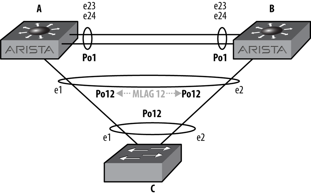
We’ll need to create a peer-link over which the two switches can communicate. This link can be a single link, but for redundancy, it should always be a port-channel containing a minimum of two physical links. In this example, there are two 24-port switches, so let’s use the last two interfaces, e23 and e24:
Arista-1(config)#int e23-24Arista-1(config-if-Et23-24)#channel-group 1 mode active
Next, we configure the port-channel to be a trunk:
Arista-1(config-if-Et23-24)#int po 1Arista-1(config-if-Po1)#switchport mode trunk
If you’re used to Cisco switches, you’ll notice that the switch did not bark at us about trunk encapsulation. Here’s what would happen on a Cisco switch:
Cisco-1(config)#int f1/0/7Cisco-1(config-if)#switchport mode trunkCommand rejected: An interface whose trunk encapsulation is "Auto" can not be configured to "trunk" mode.
Arista does not negotiate trunk encapsulation, because it only supports dot1q trunks. Cisco switches also support ISL, which is a Cisco proprietary protocol. But enough of my attention deficit issues; let’s continue.
With the port-channel configured as a trunk, we need to create a VLAN that will be used only for MLAG peer-to-peer communication. The Arista examples use VLAN 4094, so let’s keep that tradition alive:
Arista-1(config)#vlan 4094Arista-1(config-vlan-4094)#trunk group MLAG-Peer
The trunk group
MLAG-Peer command creates a trunk
group, which is a cool way of assigning VLANs to trunks. We now
need to assign the same group to the peer-link:
Arista-1(config-vlan-4094)#int po 1Arista-1(config-if-Po1)#switchport trunk group MLAG-Peer
Now, VLAN 4094 will only be included on trunks that are also
assigned to the MLAG-Peer trunk group. By doing this,
when we create a new trunk, by default VLAN 4094 will
not be included. This keeps the MLAG peer-link
traffic on this link, and only on this link (unless you add the
MLAG-Peer trunk group to another trunk, but don’t do
that).
The trunk group names for the peer VLAN should be configured to be the same on both switches. The configuration for VLANs and VLAN trunk groups must be identical in order to successfully establish an MLAG association between two switches.
Now that we know this VLAN is limited to the peer-link, we can
disable spanning-tree on the
VLAN:
Arista-1(config)#no spanning-tree vlan 4094Note that this is a global command, and not an interface command. It
will fail with a % Incomplete command message if run
from interface configuration mode since it is used to set cost and port
priority there.
Since MST is the default spanning tree protocol in use on Arista switches, and MST is not VLAN based, this command will not have the same result that it would if Rapid-PVST were enabled. It is still a best practice to disable spanning tree from the MLAG peer VLAN in case Rapid-PVST is ever enabled.
Note
Disabling STP is almost always a bad idea. In this case, the MLAG
peer-link always needs to be up in order to prevent a split brain
scenario. Since the peer-link is using a trunk group, and there’s only
one VLAN on the link, then a loop should never occur. The only way a
loop could possibly occur would be (in this example) for the
MLAG-Peer trunk group to be included on other links
from the MLAG pair. So don’t do that. Ever.
Since MLAG communicates over layer 3, we must assign an IP address to the VLAN on each side:
Arista-1(config)#int vlan 4094Arista-1(config-if-Vl4094)#ip address 10.0.0.1/30
Now, MLAG itself must be configured:
Arista-1(config)#mlagArista-1(config-mlag)#local-interface vlan 4094Arista-1(config-mlag)#peer-address 10.0.0.2Arista-1(config-mlag)#peer-link port-channel 1Arista-1(config-mlag)#domain-id MLAG-1
The commands should be relatively obvious. We’ve assigned the MLAG local interface to be the VLAN SVI we just created (VLAN 4094); we’ve told the switch that the peer for this MLAG domain is at the IP address 10.0.0.2; the peer-link is riding over port-channel 1; and the MLAG domain ID is MLAG-1.
The domain ID is the means whereby the switch differentiates different MLAG groups. This will be shown in more detail later in this chapter.
At this point, the status of the peer-link should be up. This
can be shown with the command show
mlag:
Arista-1(config-if-Po12)#sho mlag
MLAG Configuration:
domain-id : MLAG-1
local-interface : Vlan4094
peer-address : 10.0.0.2
peer-link : Port-Channel1
MLAG Status:
state : Inactive
peer-link status : Up
local-int status : Up
system-id : 00:00:00:00:00:00
MLAG Ports:
Disabled : 0
Configured : 0
Inactive : 0
Active-partial : 0
Active-full : 0The last paragraph that begins with MLAG ports shows all zeroes because we have not created any MLAGs yet. Let’s go ahead and create a simple MLAG.
In this example, I’ve set up two Arista switches (Arista-1 and Arista-2) connected to a single Cisco 3750. The two Arista switches will be forming an MLAG peer, while the Cisco switch will view the link as a regular port-channel.
The Cisco switch is configured as follows:
interface Port-channel12 switchport trunk encapsulation dot1q switchport mode trunk interface GigabitEthernet1/0/1 switchport trunk encapsulation dot1q switchport mode trunk channel-group 12 mode active ! interface GigabitEthernet1/0/2 switchport trunk encapsulation dot1q switchport mode trunk channel-group 12 mode active
This forms a simple port-channel (Po12) that is comprised of the
physical links, G1/0/1 and G1/0/2. All ports are 1 gigabit. The
port-channel will use the dot1Q protocol due to the mode active keywords in the channel-group
commands.
To minimize page flipping, let’s look at the network again. The network is shown in Figure 12-4.
At this point, the configuration for MLAG is very simple. On Arista-1, we’ll use port e1, and assign it to port-channel 12.
Note
It may be confusing to see that all three switches are using port-channel 12. Note that they do NOT need to be the same. I strongly urge you to keep them the same, at least on the MLAG peers. I’ve worked on installations where the MLAG peers shared an MLAG using different port-channel interfaces, and it was a nightmare to debug during an outage. Keep it simple, and you’ll keep your job.
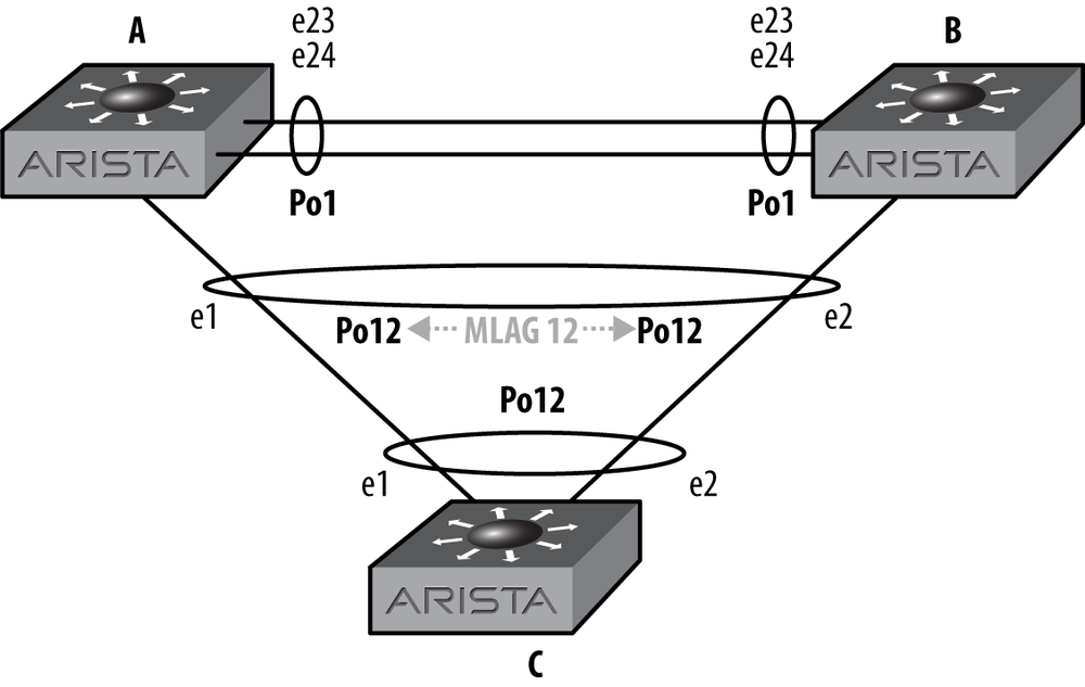
Logically, Figure 12-5 shows how switch C sees the network with MLAG enabled on switches A and B. At this point, switch C has no idea that switches A and B are two different devices, at least so far as LACP (Link Aggregation Control Protocol) is concerned.
We are using mode active on
the Arista switches in order to use LACP. Wherever possible, you should
use LACP in active mode for the greatest resiliency:
Arista-1(config)#int e1Arista-1(config-if-Et1)#channel-group 12 mode active
Now that the interface Po12 exists, we’ll assign it to mlag 12:
Arista-1(config-if-Et1)#int po 12Arista-1(config-if-Po12)#mlag 12
Note
I can’t stress this enough: please make your MLAG numbers correspond to the port-channel numbers to which they are assigned. They don’t have to match, but your life will be a living hell while you try to debug mismatched MLAGs in an outage with the CEO yelling at you while you type. Not that that’s ever happened to me.
Now we need to do the same steps on Arista-2. The only difference is
that on this switch I’m using the e2
interface:
Arista-2(config)#int e2Arista-2(config-if-Et2)#channel-group 12 mode active
Now we can configure the port-channel interface:
Arista-2(config-if-Et2)#int po 12Arista-2(config-if-Po12)#mlag 12
At this point, the MLAG should be up, but in our case, it’s not. As with every networking problem, we’ll start at the physical layer and work our way up. After seeing an orange link light on the G1/0/2 Cisco interface, I checked the interface on both sides of the link. Here is the Arista side:
Arista-2(config-if-Po12)#sho int po 12
Port-Channel12 is down, line protocol is lowerlayerdown (notconnect)
Hardware is Port-Channel, address is 001c.7301.0f19
MTU 9212 bytes
Full-duplex, 0b/s
Active members in this channel: 0
Last clearing of "show interface" counters never
5 minutes input rate 0 bps (- with framing), 0 packets/sec
5 minutes output rate 0 bps (- with framing), 0 packets/sec
0 packets input, 0 bytes
Received 0 broadcasts, 0 multicast
0 input errors
0 packets output, 0 bytes
Sent 0 broadcasts, 0 multicast
0 output errorsHmm…that doesn’t look good. Let’s see what the Cisco side says:
Cisco-1#sho int g1/0/2
GigabitEthernet1/0/2 is up, line protocol is down (suspended)
Hardware is Gigabit Ethernet, address is 000f.9080.4982
(bia 000f.9080.4982)
MTU 9000 bytes, BW 1000000 Kbit, DLY 10 usec,
reliability 255/255, txload 1/255, rxload 1/255
Encapsulation ARPA, loopback not set
Keepalive not set
Full-duplex, 1000Mb/s, link type is auto, media type is
10/100/1000BaseTX SFP
input flow-control is off, output flow-control is unsupported
ARP type: ARPA, ARP Timeout 04:00:00
Last input 00:00:01, output 00:00:01, output hang never
Last clearing of "show interface" counters never
Input queue: 0/75/0/0 (size/max/drops/flushes); Total output drops:0
Queueing strategy: fifo
Output queue: 0/40 (size/max)
5 minute input rate 0 bits/sec, 0 packets/sec
5 minute output rate 0 bits/sec, 0 packets/sec
1521 packets input, 200736 bytes, 0 no buffer
Received 1521 broadcasts (1521 multicasts)
0 runts, 0 giants, 0 throttles
0 input errors, 0 CRC, 0 frame, 0 overrun, 0 ignored
0 watchdog, 1521 multicast, 0 pause input
0 input packets with dribble condition detected
1090 packets output, 132480 bytes, 0 underruns
0 output errors, 0 collisions, 0 interface resets
0 babbles, 0 late collision, 0 deferred
0 lost carrier, 0 no carrier, 0 PAUSE output
0 output buffer failures, 0 output buffers swapped outAh! The Cisco side has suspended one of the links. Why?
Apparently some idiot forgot to configure the peer-link VLAN on Arista-2. Because there were two switches advertising two different device IDs within the same LACP bundle, the Cisco switch suspended one of them. This condition is called split brain, and is what I like to call bad. Luckily, the Cisco switch is smart enough to notice. Here’s what the Cisco switch saw with MLAG broken. First, interface G1/0/1:
Cisco-1#sho int g1/0/1 etherchannel | begin Dev IDPort Flags Priority Dev ID Age key Key Gi1/0/1 SA 32768001c.7308.fa491s 0x0 0xC Age of the port in the current state: 0d:00h:06m:24s
And next, interface G1/0/2, the other interface within the port-channel 12 bundle:
Cisco-1#sho int g1/0/2 etherchannel | begin Dev IDPort Flags Priority Dev ID Age key Key Gi1/0/2 SA 32768001c.7301.0f1714s 0x0 0xC Age of the port in the current state: 0d:00h:05m:48s
Look carefully at the device IDs. They’re different (001c.7308.fa49 versus 001c.7301.0f17). As far as the Cisco switch is concerned, there
are two different devices trying to form a single port-channel (which
there are), and that’s not allowed. Hence, the Cisco switch suspended one
of them as being invalid.
Once I fixed the VLAN issue, the following popped up on Arista-1:
Sep 27 19:58:41 Arista-1 Lag+LacpAgent: %LACP-4-PARTNER_CHURN: LACP Partner Churn Detected on Ethernet1 Sep 27 19:58:56 Arista-1 Mlag: %MLAG-4-INTF_INACTIVE_PEER: Interface Port-Channel12 is link down on the MLAG peer. MLAG 12 is inactive. Sep 27 19:58:56 Arista-1 Ebra: %LINEPROTO-5-UPDOWN: Line protocol on Interface Port-Channel12, changed state to up Sep 27 19:59:14 Arista-1 Mlag: %MLAG-6-INTF_ACTIVE: Local interface Port-Channel12 and peer interface Port-Channel12 are link up. MLAG 12 is active.
Once the MLAG became active, the Cisco switch was duped into believing that the two devices were really one. How? They both have the same device ID now. Here is the output of the same two commands we used earlier, showing the device IDs properly in sync. First for interface G1/0/1:
Cisco-1#sho int g1/0/1 etherchannel | begin Dev IDPort Flags Priority Dev ID Age key Key Gi1/0/1 SA 32768021c.7301.0f173s 0x0 0xC Age of the port in the current state: 0d:00h:08m:33s
And then for interface G1/0/2:
Cisco-1#sho int g1/0/2 etherchannel | begin Dev IDPort Flags Priority Dev ID Age key Key Gi1/0/2 SA 32768021c.7301.0f179s 0x0 0xC Age of the port in the current state: 0d:00h:08m:18s
With the MLAG working, the Arista-1 switch shows a proper status:
Arista-1#sho mlag
MLAG Configuration:
domain-id : MLAG-1
local-interface : Vlan4094
peer-address : 10.0.0.2
peer-link : Port-Channel1
MLAG Status:
state : Active
peer-link status : Up
local-int status : Up
system-id : 02:1c:73:01:0f:17
MLAG Ports:
Disabled : 0
Configured : 0
Inactive : 0
Active-partial : 0
Active-full : 1Notice that the system ID matches the device ID that we saw on the Cisco switch.
To see the status of individual MLAG interfaces, use the show mlag interfaces command:
Arista-1#sho mlag interfaces
local/remote
mlag desc state local remote status
----------------------------------------------------------------------------
12 active-full Po12 Po12 up/upHere is the output of the other switch with three configured MLAGs, of which only one is active:
Arista-2#sho mlag interfaces
local/remote
mlag desc state local remote status
----------------------------------------------------------------------------
5 configured Po5 - down/-
12 active-full Po12 Po12 up/up
34 configured Po34 - down/-If MLAG is active, but the peer’s link (not the peer-link!) is down
for whatever reason, then the status of the MLAG will be
Active-partial:
Arista-1#sho mlag
MLAG Configuration:
domain-id : MLAG-1
local-interface : Vlan4094
peer-address : 10.0.0.2
peer-link : Port-Channel1
MLAG Status:
state : Active
peer-link status : Down
local-int status : LowerLayerDown
system-id : 02:1c:73:01:0f:17
MLAG Ports:
Disabled : 0
Configured : 0
Inactive : 0
Active-partial : 1
Active-full : 0To get some detail regarding the state of MLAG in general, use
the show mlag detail command:
Arista-1#sho mlag detail
MLAG Configuration:
domain-id : MLAG-1
local-interface : Vlan4094
peer-address : 10.0.0.2
peer-link : Port-Channel1
MLAG Status:
state : Active
peer-link status : Down
local-int status : LowerLayerDown
system-id : 02:1c:73:01:0f:17
MLAG Ports:
Disabled : 0
Configured : 0
Inactive : 0
Active-partial : 1
Active-full : 0
MLAG Detailed Status:
State : primary
State changes : 8
Last state change time : 0:00:07 ago
primary-priority : 32767
Peer primary-priority : 20
Peer MAC address : 00:1c:73:01:0f:17
Reload delay : 300 seconds
Peer ports errdisabled : False
Heartbeat interval : 2000 ms
Heartbeat timeout : 5000 ms
Last heartbeat timeout : 17:43:48 ago
Heartbeat timeouts since reboot : 1
Peer monotonic clock offset : 80.151683 seconds
Agent should be running : True
P2p mount state changes : 4
Failover : True
Secondary from failover : FalseAfter rebooting the Arista-2 switch, the ports within MLAG pairs are set to ErrDisabled for 300 seconds. This allows all of the upper level protocols to stabilize before traffic is forwarded over the links. Additionally, ports don’t always come up in the order in which we might expect. For example, the peer-link should always come up first in order for MLAG to work properly, but I always configure the peer-link to be the last ports on the switch. If the switch were to initialize ports in the order in which they are shown in the configuration, then the peer-link would come up last. The delay is applied to all non-peer-link ports to prevent that from happening.
This interval is configurable with the reload-delay command within MLAG configuration,
although care should be taken when altering this value as network
instability may result when the delay is too short.
Note
The time it takes for a switch to finish booting varies based on the number of ports in the switch and the complexity of the config. For example, a 7508 with 384 ports will take a bit longer to come up than a 7124 with only 24 ports. The 300 second time was chosen as a conservative value for a typical 1RU switch. If you’re using chassis switches with hundreds of ports, the value may need to be higher.
Remember that the other link in the MLAG pair (e1 on Arista-1 in this example) is up and forwarding traffic. So long as your devices are dual homed to both switches using MLAG, they should stay online while one of the switches in the MLAG pair reboots:
Arista-2(config)#mlag configurationArista-2(config-mlag)#reload-delay ?<0-3600> Seconds
Here is the status of Arista-2’s e2 interface after a reload:
Arista-2#sho int e2
Ethernet2 is down, line protocol is down (errdisabled)
Hardware is Ethernet, address is 001c.7301.0f19 (bia 001c.7301.0f19)
MTU 9212 bytes
Auto-duplex, Auto-speed, auto negotiation: off
Last clearing of "show interface" counters never
5 minutes input rate 0 bps (- with framing), 0 packets/sec
5 minutes output rate 0 bps (- with framing), 0 packets/sec
0 packets input, 0 bytes
Received 0 broadcasts, 0 multicast
0 runts, 0 giants
0 input errors, 0 CRC, 0 alignment, 0 symbol
0 PAUSE input
0 packets output, 0 bytes
Sent 0 broadcasts, 0 multicast
0 output errors, 0 collisions
0 late collision, 0 deferred
0 PAUSE outputWhile in this state, MLAG can see the peer switch, and even acknowledges that the other half of its MLAG interface is up. That doesn’t keep me from wondering why my MLAGs are all down after rebooting a switch. When it comes to MLAGs, I’m stubbornly stupid for about two minutes, after which I remember to look and see how much time I have left:
Arista-2#sho mlag detail
MLAG Configuration:
domain-id : MLAG-1
local-interface : Vlan4094
peer-address : 10.0.0.1
peer-link : Port-Channel1
MLAG Status:
state : Active
peer-link status : Up
local-int status : Up
system-id : 02:1c:73:01:0f:17
MLAG Ports:
Disabled : 0
Configured : 0
Inactive : 0
Active-partial : 1
Active-full : 0Newer versions of EOS have more robust output for the show mlag detail command. Here’s an example from
version 4.9.3 where you can see what the reload timer is, and how much
longer you have to wait (both in bold in this example). This output also
shows that the ports are ErrDisabled in
the next line. The other switch in the MLAG pair will display Peer ports errdisabled = True in this
condition:
SW3#sho mlag detail
MLAG Configuration:
domain-id : MLAG-1
local-interface : Vlan4094
peer-address : 10.0.0.2
peer-link : Port-Channel1
MLAG Status:
state : Inactive
negotiation status : Connecting
peer-link status : Down
local-int status : LowerLayerDown
system-id : 00:00:00:00:00:00
MLAG Ports:
Disabled : 2
Configured : 0
Inactive : 0
Active-partial : 0
Active-full : 0
MLAG Detailed Status:
State : inactive
State changes : 1
Last state change time : 0:00:27 ago
primary-priority : 32767
Peer primary-priority : 0
Peer MAC address : 00:00:00:00:00:00
Reload delay : 300 seconds
Reload delay time left : 273 seconds
Ports errdisabled : True
Lacp standby : False
Heartbeat interval : 2000 ms
Heartbeat timeout : 5000 ms
Last heartbeat timeout : never
Heartbeat timeouts since reboot : 0
Peer monotonic clock offset : unknown
Agent should be running : True
P2p mount state changes : 0
Failover : False
Secondary from failover : FalseAfter 300 seconds, the interface comes back up automatically, and the MLAG becomes active. Here is the status for the physical interface on Arista-2:
Arista-2#sho int e2
Ethernet2 is up, line protocol is up (connected)
Hardware is Ethernet, address is 001c.7301.0f19 (bia 001c.7301.0f19)
MTU 9212 bytes, BW 1000000 Kbit
Full-duplex, 1Gb/s, auto negotiation: on
Last clearing of "show interface" counters never
5 minutes input rate 103 bps (0.0% with framing), 0 packets/sec
5 minutes output rate 280 bps (0.0% with framing), 0 packets/sec
14 packets input, 4113 bytes
Received 0 broadcasts, 14 multicast
0 runts, 0 giants
0 input errors, 0 CRC, 0 alignment, 0 symbol
0 PAUSE input
84 packets output, 11060 bytes
Sent 0 broadcasts, 7 multicast
0 output errors, 0 collisions
0 late collision, 0 deferred
0 PAUSE outputHere is the MLAG status on Arista-2 after 300 seconds has passed:
Arista-2#sho mlag
MLAG Configuration:
domain-id : MLAG-1
local-interface : Vlan4094
peer-address : 10.0.0.1
peer-link : Port-Channel1
MLAG Status:
state : Active
peer-link status : Up
local-int status : Up
system-id : 02:1c:73:01:0f:17
MLAG Ports:
Disabled : 0
Configured : 0
Inactive : 0
Active-partial : 0
Active-full : 1I’ve been promising that I’d explain when to use multiple MLAG IDs all through this chapter, so I think it’s time to deliver.
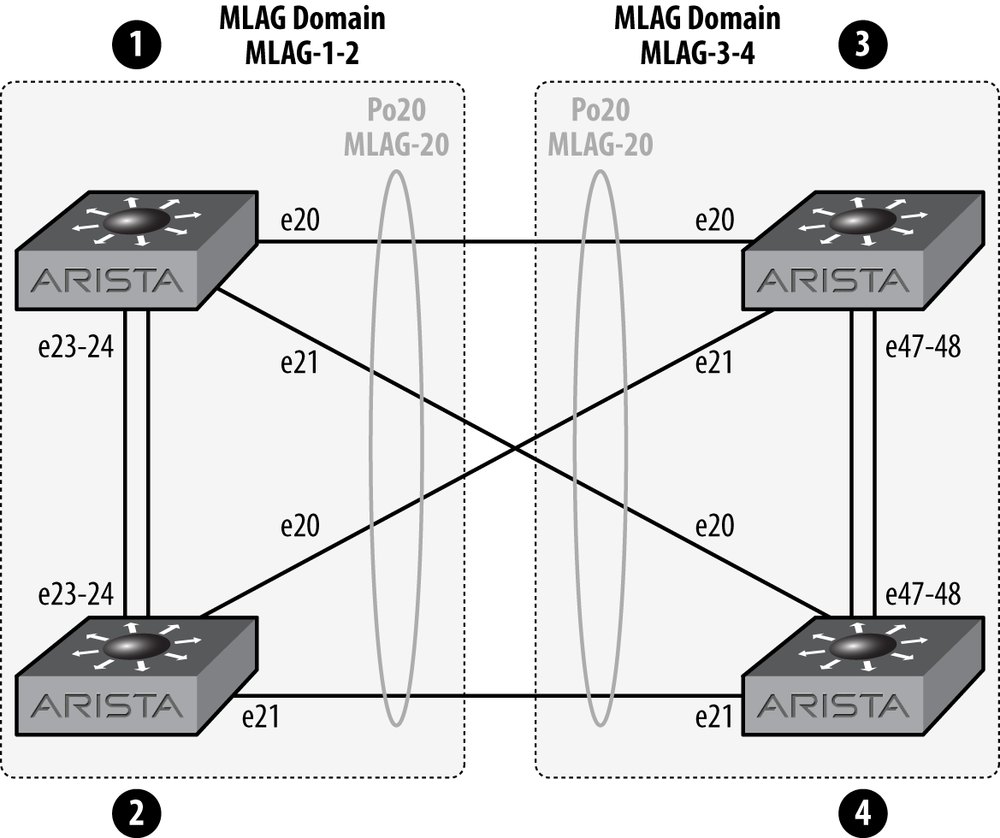
If you need to connect one MLAG pair to another MLAG pair, each pair should have its own MLAG domain ID. Let’s take a look. The network layout for what we’re discussing is shown in Figure 12-6.
The two switches on the left (1 and 2) are an MLAG pair, and the two switches on the right (3 and 4) are an MLAG pair. In order to connect them together as shown, each pair should have its own MLAG Domain ID. Why? Let’s think about that for a minute. If 1, 3, and 4 were all configured in the same domain, then things might get pretty confusing for the switches.
What you’ll find if you build this though, is that it will work if they all have the same MLAG domain. So why require an MLAG domain at all? My guess would be that between the MLAG domains and the use of IP addresses in the MLAG peer-link, future versions of EOS might support MLAG between multiple (as in more than two) switches. Although I have no proof of this, I would recommend making all of your MLAG peer-links have unique IP networks and MLAG domains, especially in environments where multiple MLAG domains can reach each other. Sure, the trunk group feature helps to isolate the MLAG IP addresses, but I always like to err on the side of possibility.
MLAG ISSU (In-Service Software Upgrade) is a feature enabled on EOS version 4.9.3 and later. With MLAG ISSU, you can upgrade an MLAG switch pair with minimal (sub-second) packet loss and no STP reconvergence. Without MLAG ISSU, or if you upgrade while ignoring the switch’s dire warnings regarding the state of MLAG ISSU, you’ll likely have one or more network topology changes that will result in one or more STP reconvergence events, and no one wants that.
The Arista documentation on MLAG ISSU indicates that the following steps need to be followed in this order to properly upgrade an MLAG ISSU switch pair:
Verify primary/secondary state of MLAG on each switch using the
show mlag detailcommand, or to be brief, theshow mlag det | grep State(with a capital “S”) command.Ensure configuration consistencies.
Resolve ISSU warnings (from the output of reload).
Upgrade MLAG secondary switch.
Monitor MLAG status using
show mlag
        detail
.
Confirm MLAG secondary status.
Upgrade MLAG primary peer switch.
Confirm overall MLAG status.
Note
When upgrading 7500 peers with dual supervisors, you’ll need to upgrade the standby supervisors on both switches, then upgrade the active supervisor on the MLAG secondary, and finally the last remaining supervisor.
By having switches running MLAG ISSU code, the switches will know if they can be upgraded without causing an outage. If they cannot, then the switch will give you a warning when rebooting. Here’s an example of such a warning on a switch running 4.9.3:
SW4(config)#reload
If you are performing an upgrade, and the Release Notes for the new
version of EOS indicate that MLAG is not backwards-compatible with the
currently installed version (4.9.3), the upgrade will result in packet
loss.

The following MLAGs are not in Active mode. Traffic to or from these
ports will be lost during the upgrade process:
                                                          local/remote
  mlag       desc             state       local  remote     status
--------- ---------- -------------- ----------- --------- ------------
    10               active-partial        Po10         -         up/-
    20               active-partial        Po20         -         up/-
    26               active-partial        Po26         -         up/-

Stp is not restartable. Topology changes will occur during the upgrade
process.


Proceed with reload? [confirm]
Warning
Using the reload now command
will cause the switch to bypass these warnings, so don’t use the
reload now command when doing an MLAG
ISSU upgrade.
Here’s a list of common ISSU warnings and the way to resolve them.
- Compatibility check
The version you’re upgrading to might not be compatible with the version you’re on. But then again, it might! Read the release note to make sure that it is.
- Active-partial MLAG warning
The MLAG shown is not active on the other switch in the MLAG pair. If it should be, then bring it up. If not, you can ignore this message (often seen if the requirements have changed but the old config is still in place).
- STP is not restartable
Usually waiting 30 to 120 seconds will reward you with this warning resolving itself. To see the status of STP restartability (I totally made that word up), use the show spanning tree bridge detail command:
Arista-10#sho spanning-tree bridge detail | inc agentStp agent is restartable- Reload delay too low
Remember the reload delay we talked about earlier in this chapter? Well, if the switch thinks that that it’s too low (lower than the default of 300 seconds for top-of-rack switches and 600 seconds for modular switches), it will bark at you with this warning.
- Peer has
errdisabledinterfaces This is usually an indication that you’re impatient and haven’t waited long enough for the peer to reboot. Remember, the peer’s MLAG-enabled interfaces will stay in an
errdisabledstate for the duration of the reload delay after booting, assuming the other switch is up, and if you’re on a switch that shows this warning, that’s a good assumption.
The biggest step you should take before considering an MLAG ISSU upgrade is to carefully read the release notes and TOI (Transfer of Information) documents found on the Arista support site. They can be found alongside the EOS binary images. Don’t be afraid to call or email your Arista sales engineer or open a TAC case either. Some shops don’t do upgrades often enough to remain sharp on the syntax and gotchas, and these folks love to help.
Remember, not all versions of EOS support MLAG ISSU, only 4.9.3 and later. Also, there will likely be versions where you won’t be able to upgrade to using ISSU. For example, if and when EOS gets to version 38.3.2, I doubt you’ll be able to upgrade using MLAG ISSU from 4.9.3, but hey, those Arista developers are pretty sharp, so you never know.