
Spanning tree protocol (STP) is very important in layer-2 networks, and its impact should be clearly understood when designing or even troubleshooting a network. If you’ve been around Cisco gear for the majority of your networking life, you’ve probably used Per-VLAN Spanning Tree (PVST) or Rapid-PVST (RPVST). In this chapter, I’m going to primarily cover a form of STP that is becoming more common in large data centers: Multiple Spanning Tree (MST).
Data center networks have very different requirements than enterprise networks do. For example, few of the enterprise networking professionals I meet know that many switches have spanning tree limitations. I worked for a client that had Cisco 3750s in the core of a small data center. Things seemed to work alright until they added the 257th VLAN, and that’s when they learned that Cisco 3750s only support STP up to 256 VLANs. Bummer.
I was brought in to help solve the problem, and after my recommendation of, “Buy data center class chassis switches” was ignored, I looked for other options. That’s when I learned about MST.
Arista switches can run a variety of STP types. You can change the
type using the spanning-tree mode
mode-type command:
SW1(config)#spanning-tree mode ?
  mstp        Multiple spanning tree protocol
  none        Disable spanning tree
  rapid-pvst  Per VLAN rapid spanning tree protocol
  rstp        Rapid spanning tree protocol
Since I’ve covered spanning tree and rapid-PVST in Network Warrior, I’m going to focus mostly on MST in this chapter. Buckle up, because if you’ve never used MST, you’re in for a fun ride.
MST is a version of STP that is much simpler than PVST, yet I rarely see it implemented. I think a big part of that is due to the fact that there is very little documentation out there, and what is available, well, let’s just say that reading ancient Sumerian would be easier.
MST appears to be very difficult, but it doesn’t need to be. Like anything technical, if you make it too complicated it will be difficult to understand, so keep it simple and you’ll do fine. MST can be simpler to configure, easier to manage, often makes more sense (when deployed simply), and uses less CPU cycles than PVST. When I discovered that Arista switches were configured with MST as the default, it was love at first sight. Hey, I never said I wasn’t a nerd.
MST is based on Rapid Spanning Tree Protocol (RSTP), which is a great thing because it offers some great backwards compatibility as we’ll see later in this chapter. If you’re thinking, well, isn’t PVST multiple spanning trees?, you’re right, but MST works differently. The problem with PVST is that there’s a spanning tree instance running for every VLAN. On an enterprise network comprised of 20 or 30 (or even 100) VLANs, that’s not a big deal. In a data center, where there may easily be hundreds of VLANs, things start to get problematic.
First, each spanning tree instance requires CPU and memory resources, and unless you’re a fan of the old even VLANs on the left and odd VLANs on the right, then all the VLANs will likely have the same topology anyway. Let’s say you are a fan of splitting your VLANs up between two core switches (I am not), then you’ve got two topologies (assuming all trunks allow all VLANs, of course). Why have potentially hundreds of spanning tree instances running when there are only two topologies?
Note
I have never been a fan of splitting up STP topologies with odd/even VLANs. It makes troubleshooting harder, and simply isn’t needed in most modern networks. Fifteen years ago, when switches were slow, I could see needing to distribute the load, but in a modern network, I’ll take simplicity every time. Besides, with MLAG, VARP, and other cool features available in Arista switches, there’s no need for any of this manual load-balancing nonsense any more.
MST allows you to have one spanning tree instance for all your VLANs. Or, if you’re still hell bent on balancing which switch is the root based on some arbitrary pattern such as even/odd, you can split your VLANs up into instances, each with its own root. Oh, and MST is a standards-based protocol. There are no proprietary things to worry about, and it works with any vendor’s switch that supports it.
Warning
There are some vendor-interaction complexities with MST, as we’ll see later in this chapter, but rest assured, MST is still an open standard.
The MST documentation goes into painful detail about MST, the CST, the IST, the MSTI, the CIST, and who knows what else. I’ll explain all this to you, and show you why it doesn’t need to be all that difficult. Naturally, I’ll do this in a way that makes sense to me, and seems to make sense to people I teach. My goal is not to get you certified; my goal is to make you understand.
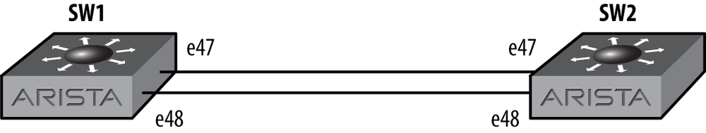
Let’s start with a simple scenario to see how MST works. In Figure 13-1, there are two switches: SW1 and SW2. These two switches are connected together with two links.
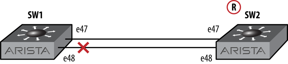
Of course, such a topology is a problem because it creates a loop, and loops are bad. Spanning tree, in its default state on Arista switches, shuts down one of the links, as shown in Figure 13-2. For details about which link gets blocked, I recommend the excellent chapter on Spanning Tree in Network Warrior (can that guy write or what?). For now, suffice to say that the blocked port is the interface farthest from the root bridge. In my little network, SW2 won the battle for root bridge status (everything is set to defaults for now) so the e48 interface on SW1 ended up blocking.
This simple network shouldn’t be a surprise to anyone who has ever used spanning tree, but the difference is that out of the box, Arista switches use MST, so let’s take a look at what the switches report.
The command to show STP information is the same as it is in IOS:
show spanning-tree. Here’s the output
for SW1:
SW1#sho spanning-tree
MST0
  Spanning tree enabled protocol mstp
  Root ID    Priority    32768
             Address     001c.7317.4a8e
             Cost        0 (Ext) 2000 (Int)
             Port        47 (Ethernet47)
             Hello Time  2.000 sec Max Age 20 sec Forward Delay 15 sec

  Bridge ID  Priority    32768  (priority 32768 sys-id-ext 0)
             Address     001c.7317.5da2
             Hello Time  2.000 sec Max Age 20 sec Forward Delay 15 sec

Interface        Role       State      Cost      Prio.Nbr Type
---------------- ---------- ---------- --------- -------- ------------
Et47             root       forwarding 2000      128.47   P2p
Et48             alternate  discarding 2000      128.48   P2p
This output shows the information we’d need when looking at STP, including the root bridge’s information, which includes the root bridge’s priority (the default is 32,768), the root bridge’s MAC address, this bridge’s priority, this switch’s MAC address, and the status of every interface that has received Bridge Protocol Data Units (BPDUs). This output clearly shows that interface Et47 is the root port, and that interface Et48 is the alternate root port, which is blocking (discarding).
Here’s the output for SW2:
SW2#sho spanning-tree
MST0
  Spanning tree enabled protocol mstp
  Root ID    Priority    32768
             Address     001c.7317.4a8e
             This bridge is the root

  Bridge ID  Priority    32768  (priority 32768 sys-id-ext 0)
             Address     001c.7317.4a8e
             Hello Time  2.000 sec Max Age 20 sec Forward Delay 15 sec

Interface        Role       State      Cost      Prio.Nbr Type
---------------- ---------- ---------- --------- -------- ------------
Et47             designated forwarding 2000      128.47   P2p
Et48             designated forwarding 2000      128.48   P2p
This switch shows that it is the root and the bridge information for itself. The ports on this switch are both designated since it’s the root bridge.
The thing to notice is the first line of output on both switches. On this line, they each say MST0.
MST0 is the default instance in MST. I’ll cover instances in a minute, but the thing to remember now is that MST0 is always on, it’s always active, and every interface forwards MST0 BPDUs. You cannot disable MST0. That will become important later on in this chapter, but for now, understand that because MST0 is always on, if you connect two switches running MST together like I have, then MST will run and behave as you’d expect.
To that end, I’d like to make SW1 the root bridge because I can’t
sleep knowing that a higher numbered switch (SW2 versus SW1) is in charge.
There are a couple of ways to do this, the simplest being the spanning-tree
root primary command:
SW1(config)#spanning-tree root primaryThis has the almost immediate effect of making SW1 the root. Here’s the proof that the STP bridge priority is now 8,192:
SW1(config)#sho spanning-tree
MST0
  Spanning tree enabled protocol mstp
  Root ID    Priority    8192
             Address     001c.7317.5da2
             This bridge is the root

  Bridge ID  Priority     8192  (priority 8192 sys-id-ext 0)
             Address     001c.7317.5da2
             Hello Time  2.000 sec Max Age 20 sec Forward Delay 15 sec

Interface        Role       State      Cost      Prio.Nbr Type
---------------- ---------- ---------- --------- -------- ------------
Et47             designated forwarding 2000      128.47   P2p
Et48             designated forwarding 2000      128.48   P2p
I say almost immediate because MST is fast. I’ve done mass switch migrations to MST and was amazed that after changing over 200 switches, we never once noticed an outage or disruption of service. Like RSTP, MST has much tighter timers than traditional spanning tree. This speed is one of the things that I like about MST, and it is one of the reasons that I recommend its use.
Another way to change the priority is with the spanning-tree priority
priority-value command. Here I’ll goose the
priority up a notch to 4,096:
SW1(config)#spanning-tree priority 4096SW1(config)#sho spanning-treeMST0 Spanning tree enabled protocol mstp Root ID Priority 4096 Address 001c.7317.5da2 This bridge is the root Bridge ID Priority 4096 (priority 4096 sys-id-ext 0) Address 001c.7317.5da2 Hello Time 2.000 sec Max Age 20 sec Forward Delay 15 sec Interface Role State Cost Prio.Nbr Type ---------------- ---------- ---------- --------- -------- ------------ Et47 designated forwarding 2000 128.47 P2p Et48 designated forwarding 2000 128.48 P2p
Note that the spanning-tree
priority command only works on MST0, which will make more sense
in a bit.
One of the things that is not terribly obvious is that MST does not care about VLANs in its default state. Whenever I explain MST to someone, this is one of the hardest things for them to wrap their heads around, likely because we’ve all used PVST for years, if not decades.
Remember when I wrote that MST0 is active on all interfaces at all times? It does so because MST, in its basic form, has no concept of VLANs. So long as MST0 can see another bridge (or BPDUs from that bridge to be precise), there’s a link to that bridge, and MST will act accordingly.
One of the other things special about MST0 is that it will interact with a switch that’s running RPVST. How can it do this if it doesn’t comprehend VLANs? That depends on the vendor, but in a nutshell, the switches will interoperate because MST is based on RSTP.
On a Cisco switch, MST0 sends identical BPDUs out every VLAN on every interface. How is that not RPVST? The difference is that it sends the same BPDU out every VLAN (that of MST0), not VLAN-specific BPDUs. This is a very important distinction to understand, because it can bite you if you’re not careful. With the Cisco model, if you configure MST0 with a priority of 4,096, then it will likely become the root bridge on every VLAN on an attached PVST switch.
Note
I worked in a network that had STP problems due to old switches that didn’t support more than 256 STP-active VLANs. To counter this, they turned STP off on new VLANs. When we migrated to MST, the core (which should be migrated first) went from only advertising BPDUs on 256 VLANs to advertising BPDUs on all 400 VLANs! The CPU on the core went down because it didn’t have to process 400 different BPDUs on 400 VLANs, but the attached switches’ CPUs went through the roof because they suddenly had 400 VLANs worth of BPDUs to deal with. The attached switches, which were still running PVST, had no idea about MST yet, so they had to process almost twice as many BPDUs as before, and since STP is a CPU-based process, their CPU utilization skyrocketed. Once we migrated them to MST, they settled down nicely.
Arista switches, at least up to EOS version 4.9.3.2, only send MST0 BPDUs on the default VLAN (VLAN1 by default). Since I had first used MST on Cisco switches, and had grown accustomed to the way they sent BPDUs on every VLAN, I was convinced that I had found a bug when my Arista switches didn’t behave the same way. When I talked to Arista about it, they pointed out that there is nothing in the RFCs that specifies BPDUs for MST0 being sent out every VLAN. In fact, since Cisco’s PVST doesn’t adhere to the original standards, I could argue that Arista is doing it right while Cisco has added their own additional feature, as they often do.
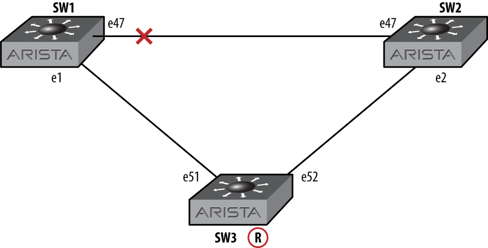
So what does this all mean for you in the real world? Let’s take a look. I’ve built a small lab with three switches (SW1, SW2, and SW3), as shown in Figure 13-3. SW1 has a priority of 8,192, SW2 has a priority of 32,768 (the default), and SW3 (the one in the middle of the drawing) has a priority of 4,096. There are two VLANs configured that span all three switches: VLAN 100 and VLAN 200. The links between the switches are trunks with all VLANs permitted.
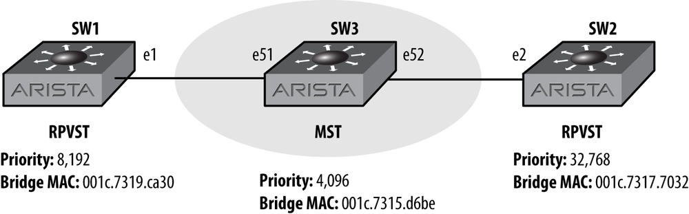
If all three of these switches were running Rapid PVST, then SW3 would be the root for all VLANs. With MST thrown in the middle, things change a bit, and unless you’re careful, the results may surprise you.
First, let’s take a quick look at SW3 in the middle:
SW3#sho spanning-tree
MST0
  Spanning tree enabled protocol mstp
  Root ID    Priority    4096
             Address     001c.7315.d6be
             This bridge is the root

  Bridge ID  Priority     4096  (priority 4096 sys-id-ext 0)
             Address     001c.7315.d6be
             Hello Time  2.000 sec Max Age 20 sec Forward Delay 15 sec

Interface        Role       State      Cost      Prio.Nbr Type
---------------- ---------- ---------- --------- -------- ------------
Et51             designated forwarding 2000      128.51   P2p Boundary
Et52             designated forwarding 2000      128.52   P2p Boundary
Looks simple enough. This bridge is the root, and other than it having a priority of 4,096, it appears as if the switch is pretty much in a default configuration. Now let’s take a look at SW1, which is running RPVST:
SW1#sho spanning-tree
VL1
  Spanning tree enabled protocol rapid-pvst
  Root ID    Priority    4096
             Address     001c.7315.d6be
             Cost        2000 (Ext) 0 (Int)
             Port        1 (Ethernet1)
             Hello Time  2.000 sec Max Age 20 sec Forward Delay 15 sec

  Bridge ID  Priority     8193  (priority 8192 sys-id-ext 1)
             Address     001c.7319.ca30
             Hello Time  2.000 sec Max Age 20 sec Forward Delay 15 sec

Interface        Role       State      Cost      Prio.Nbr Type
---------------- ---------- ---------- --------- -------- ------------
Et1              root       forwarding 2000      128.1    P2p

VL100
  Spanning tree enabled protocol rapid-pvst
  Root ID    Priority    8292
             Address     001c.7319.ca30
             This bridge is the root

  Bridge ID  Priority     8292  (priority 8192 sys-id-ext 100)
             Address     001c.7319.ca30
             Hello Time  2.000 sec Max Age 20 sec Forward Delay 15 sec

Interface        Role       State      Cost      Prio.Nbr Type
---------------- ---------- ---------- --------- -------- ------------
Et1              designated forwarding 2000      128.1    P2p

VL200
  Spanning tree enabled protocol rapid-pvst
  Root ID    Priority    8392
             Address     001c.7319.ca30
             This bridge is the root

  Bridge ID  Priority     8392  (priority 8192 sys-id-ext 200)
             Address     001c.7319.ca30
             Hello Time  2.000 sec Max Age 20 sec Forward Delay 15 sec

Interface        Role       State      Cost      Prio.Nbr Type
---------------- ---------- ---------- --------- -------- ------------
Et1              designated forwarding 2000      128.1    P2p
Certainly, the output of the show spanning tree command is different due to this switch running RPVST instead of MST, but look at the VLANs and their respective root bridges. VLAN1 (the default VLAN) shows that SW3 is the root, while all the other VLANs show themselves to be the root. This is due to the fact that MST does not send out BPDUs on every VLAN, only the default VLAN (VLAN1 in this example).
Now let’s look at SW2. Can you guess what it will show?
SW2#sho spanning-tree
VL1
  Spanning tree enabled protocol rapid-pvst
  Root ID    Priority    4096
             Address     001c.7315.d6be
             Cost        2000 (Ext) 0 (Int)
             Port        2 (Ethernet2)
             Hello Time  2.000 sec Max Age 20 sec Forward Delay 15 sec

  Bridge ID  Priority    32769  (priority 32768 sys-id-ext 1)
             Address     001c.7317.7032
             Hello Time  2.000 sec Max Age 20 sec Forward Delay 15 sec

Interface        Role       State      Cost      Prio.Nbr Type
---------------- ---------- ---------- --------- -------- ------------
Et2              root       forwarding 2000      128.2    P2p

VL100
  Spanning tree enabled protocol rapid-pvst
  Root ID    Priority    8292
             Address     001c.7319.ca30
             Cost        2000 (Ext) 0 (Int)
             Port        2 (Ethernet2)
             Hello Time  2.000 sec Max Age 20 sec Forward Delay 15 sec

  Bridge ID  Priority    32868  (priority 32768 sys-id-ext 100)
             Address     001c.7317.7032
             Hello Time  2.000 sec Max Age 20 sec Forward Delay 15 sec

Interface        Role       State      Cost      Prio.Nbr Type
---------------- ---------- ---------- --------- -------- ------------
Et2              root       forwarding 2000      128.2    P2p

VL200
  Spanning tree enabled protocol rapid-pvst
  Root ID    Priority    8392
             Address     001c.7319.ca30
             Cost        2000 (Ext) 0 (Int)
             Port        2 (Ethernet2)
             Hello Time  2.000 sec Max Age 20 sec Forward Delay 15 sec

  Bridge ID  Priority    32968  (priority 32768 sys-id-ext 200)
             Address     001c.7317.7032
             Hello Time  2.000 sec Max Age 20 sec Forward Delay 15 sec

Interface        Role       State      Cost      Prio.Nbr Type
---------------- ---------- ---------- --------- -------- ------------
Et2              root       forwarding 2000      128.2    P2p
SW2 (the rightmost switch in Figure 13-3) shows that, again, SW3 is the root for VLAN1, but SW1 is the root for all the remaining VLANs! It’s almost like RPVST BPDUs were tunneled through MST or something. In a way, that’s not far from the truth.
SW3 is the root on VLAN1 for the same reason that SW1 saw SW3 as the root. Since MST operates on the default VLAN, this makes perfect sense.
RPVST uses a multicast MAC address (01:80:C2:00:00:00) to send BPDUs, and sends BPDUs on all VLANs. Switches not configured for multicast flood these packets out all ports on the respective VLAN, so when SW1 sends out its BPDUs, SW3 forwards them, but doesn’t process them because MST does not listen for BPDUs on VLANs other than the default. The BPDUs from SW1 are then received by SW2, which processes them due to it running RPVST.
This behavior is different than what you would see with a Cisco switch in the middle. With a Cisco switch running MST in the middle (configured with the same priority of 4,096), the Cisco switch would become the root bridge for all VLANs. This is due to the fact that Cisco enhanced the MST protocol to have this effect.
Warning
Watch out! If you’ve designed a network with a Cisco switch in the core running MST, and you’ve got PVST switches attached to it, replacing that Cisco core switch with an Arista switch will likely change the STP root bridge on most of the VLANs in your network. If you don’t have a root bridge configured for your VLANs in this scenario, they will negotiate one, and it may not be the one that you would otherwise prefer.
Additionally, with an Arista switch in the core running MST, if you add switches to it that are running PVST, they will either become the root for the nondefault VLANs, or they will negotiate with other PVST switches on your network through the MST core.
OK, so MST0 works as expected, and it’s simple, and we know how to change the root bridge. We’ve seen how it behaves with RPVST attached, which is interesting, but for many environments, that’s good enough. Let’s dig in a bit and see how a more complicated scenario might look.
MST0 is only the tip of the iceberg when it comes to MST. Though MST is not a PVST in the sense that BPDUs are not sent out every VLAN, it has the ability to separate groups of VLANs into separate spanning trees. How is that different than PVST? Imagine that you have 400 VLANs active on your network. With PVST, you would have 400 spanning tree instances, each with its own root bridge, and each one sending out BPDUs aplenty.
With MST, BPDUs are only ever sent over VLAN1 (by default), but VLANs can be grouped into MST instances. For example, you could put VLAN 100 into MST1, 200 into MST2, 300 into MST3, and 400 to 499 into MST4.
With your VLANs grouped like this, you could still do some manual splitting by making one core switch the root for MST1 and MST3, while another switch could be the root for MST2 and MST4. As I wrote earlier, I’m not a fan of this type of manual balancing, but I do like to have options, and my customers’ desires often override my recommendations anyway.
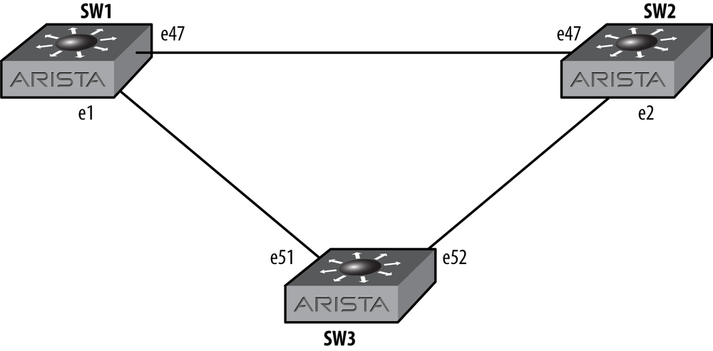
To keep things simple, I’ll use the network in Figure 13-4 for the next examples. This network has only three VLANs, VLAN 100, 200, and 300, all of which are active on all switches and trunked on all links. Note that these are the same switches I used earlier, and I’ve just changed the connections to form a loop while also configuring all three switches for MST.
To start things off, I’m going to create a new MST instance.
Many of the commands for MST are done in the spanning-tree mst configuration mode. Like many
other such modes, changes do not take effect until you exit the
mode:
SW1(config)#spanning-tree mst configuration
SW1(config-mst)#
In order to add a new MST instance, use the command instance, followed by the instance
number, and then the VLANs to be included in the instance. To
place VLAN 100 into MST instance 1, I’ll use the instance 1 vlan 100 command. Note that VLANs can
be listed individually, separated by commas, or listed as ranges:
SW1(config-mst)#instance 1 vlans 100Now, I’ll put VLANs 200 and 300 into MST instance 2:
SW1(config-mst)#instance 2 vlans 200,300Once I exit, spanning tree will be configured, and I should see three instances in MST instead of one:
SW1(config-mst)#exitSW1(config)#exitSW1#sho spanning-treeMST0 Spanning tree enabled protocol mstp Root ID Priority 4096 Address 001c.7315.d6be Cost 2000 (Ext) 0 (Int) Port 1 (Ethernet1) Hello Time 2.000 sec Max Age 20 sec Forward Delay 15 sec Bridge ID Priority 8192 (priority 8192 sys-id-ext 0) Address 001c.7319.ca30 Hello Time 2.000 sec Max Age 20 sec Forward Delay 15 sec Interface Role State Cost Prio.Nbr Type ---------------- ---------- ---------- --------- -------- ------------ Et1 root forwarding 2000 128.1 P2p Boundary Et47 alternate discarding 2000 128.47 P2p Boundary MST1 Spanning tree enabled protocol mstp Root ID Priority 32769 Address 001c.7319.ca30 This bridge is the root Bridge ID Priority 32769 (priority 32768 sys-id-ext 1) Address 001c.7319.ca30 Hello Time 2.000 sec Max Age 20 sec Forward Delay 15 sec Interface Role State Cost Prio.Nbr Type ---------------- ---------- ---------- --------- -------- ------------ Et1 master forwarding 2000 128.1 P2p Boundary Et47 alternate discarding 2000 128.47 P2p Boundary MST2 Spanning tree enabled protocol mstp Root ID Priority 32770 Address 001c.7319.ca30 This bridge is the root Bridge ID Priority 32770 (priority 32768 sys-id-ext 2) Address 001c.7319.ca30 Hello Time 2.000 sec Max Age 20 sec Forward Delay 15 sec Interface Role State Cost Prio.Nbr Type ---------------- ---------- ---------- --------- -------- ------------ Et1 master forwarding 2000 128.1 P2p Boundary Et47 alternate discarding 2000 128.47 P2p Boundary
MST0 still sees SW3 as the root from my earlier example, but all the other VLANs show SW1 to be the root. This is because the other VLANs are in different MST regions on this switch than they are on the other two. This is where MST confuses people, so hang on and let’s examine what’s really happening. To make things a bit clearer, Figure 13-5 shows a visual representation of what’s going on.
First, MST0 continues to function the way it always has. MST1 and MST2 are new regions, but they only exist on SW1. So what happens to these VLANs on switches SW2 and SW3? Let’s take a look. Here’s SW2:
SW2#sho spanning-tree
MST0
  Spanning tree enabled protocol mstp
  Root ID    Priority    4096
             Address     001c.7315.d6be
             Cost        0 (Ext) 2000 (Int)
             Port        2 (Ethernet2)
             Hello Time  2.000 sec Max Age 20 sec Forward Delay 15 sec

  Bridge ID  Priority    32768  (priority 32768 sys-id-ext 0)
             Address     001c.7317.7032
             Hello Time  2.000 sec Max Age 20 sec Forward Delay 15 sec

Interface        Role       State      Cost      Prio.Nbr Type
---------------- ---------- ---------- --------- -------- ------------
Et2              root       forwarding 2000      128.2    P2p
Et47             designated forwarding 2000      128.47   P2p Boundary
And here’s the same output from SW3:
SW3#sho spanning-tree
MST0
  Spanning tree enabled protocol mstp
  Root ID    Priority    4096
             Address     001c.7315.d6be
             This bridge is the root

  Bridge ID  Priority     4096  (priority 4096 sys-id-ext 0)
             Address     001c.7315.d6be
             Hello Time  2.000 sec Max Age 20 sec Forward Delay 15 sec

Interface        Role       State      Cost      Prio.Nbr Type
---------------- ---------- ---------- --------- -------- ------------
Et51             designated forwarding 2000      128.51   P2p Boundary
Et52             designated forwarding 2000      128.52   P2p
So they both see SW3 as the root, just like SW1 did, but they only show MST0. So why are the new MST instances that only exist on SW1 blocking port Et47?
The key to this, and many of the complexities than can result when using MST, lies in the fact that these interfaces are what MST calls boundary ports. A boundary port is one that connects to something other than the instance for which that port is configured. Look at the last two lines from SW3’s output, shown previously. Interface Et51 shows a port type of P2p Boundary, while Et52 shows a port type of P2p. Look again at the drawing in Figure 13-5, and remember that only SW1 is configured for MST instances 1 and 2 at this point. Port Et51 on SW3 is connected to SW1, which is configured differently than SW3, while Et52 is connected to SW2, which still has the same configuration. Technically, there’s more to it than the configurations being different, but we’ll get to that in a minute. For now, understand that the switch sees the connected device as different, and therefore outside of this switch’s MST configuration.
There are a few common scenarios that will result in boundary ports. First, when a switch configured with spanning tree protocol other than MST is attached, the port will be put into a boundary state. Look at the example where I put an MST switch in the middle of two RPVST switches in Figure 13-3 and you’ll see two boundary ports. These ports are a result of MST being connected to RPVST switches.
To make the network a bit more logical, I’m going to configure
SW1 to be the root for all of our new MST instances (but not MST0). This
is done in global configuration mode with the spanning-tree mst
instance-number priority
priority-value command. You can also specify
the word root instead of priority
priority-value:
SW1(config)#spanning-tree mst 1 priority 8192SW1(config)#spanning-tree mst 2 priority 8192
Another reason that ports will be configured as boundary ports is when MST is running on both switches, but the instances don’t match. When attached switches are in the same MST instance, they form a region. To be painfully accurate, the switches need to have matching regions, with matching VLAN-to-region mapping, and the same configuration names. This leads me to one of the main points of confusion (and misconfiguration) I’ve seen in the field when using MST. Let me show you what I mean, since it’s easier to see firsthand. I’ll now configure SW2 to have the same MST–VLAN mappings, but I’ll add a configuration name, which will force the switches to be in different regions, even though they have the same instance numbers.
SW2(config)#spanning-tree mst configurationSW2(config-mst)#instance 1 vlan 100SW2(config-mst)#instance 2 vlan 200,300SW2(config-mst)#name Switch2SW2(config-mst)#exit
Here’s how SW2 sees its world with regard to spanning tree:
SW2#sho spanning-tree
MST0
  Spanning tree enabled protocol mstp
  Root ID    Priority    4096
             Address     001c.7315.d6be
             Cost        2000 (Ext) 0 (Int)
             Port        2 (Ethernet2)
             Hello Time  2.000 sec Max Age 20 sec Forward Delay 15 sec

  Bridge ID  Priority    32768  (priority 32768 sys-id-ext 0)
             Address     001c.7317.7032
             Hello Time  2.000 sec Max Age 20 sec Forward Delay 15 sec

Interface        Role       State      Cost      Prio.Nbr Type
---------------- ---------- ---------- --------- -------- ------------
Et2              root       forwarding 2000      128.2    P2p Boundary
Et47             alternate  discarding 2000      128.47   P2p Boundary

MST1
  Spanning tree enabled protocol mstp
  Root ID    Priority    32769
             Address     001c.7317.7032
             This bridge is the root

  Bridge ID  Priority    32769  (priority 32768 sys-id-ext 1)
             Address     001c.7317.7032
             Hello Time  2.000 sec Max Age 20 sec Forward Delay 15 sec

Interface        Role       State      Cost      Prio.Nbr Type
---------------- ---------- ---------- --------- -------- ------------
Et2              master     forwarding 2000      128.2    P2p Boundary
Et47             alternate  discarding 2000      128.47   P2p Boundary

MST2
  Spanning tree enabled protocol mstp
  Root ID    Priority    32770
             Address     001c.7317.7032
             This bridge is the root

  Bridge ID  Priority    32770  (priority 32768 sys-id-ext 2)
             Address     001c.7317.7032
             Hello Time  2.000 sec Max Age 20 sec Forward Delay 15 sec

Interface        Role       State      Cost      Prio.Nbr Type
---------------- ---------- ---------- --------- -------- ------------
Et2              master     forwarding 2000      128.2    P2p Boundary
Et47             alternate  discarding 2000      128.47   P2p Boundary
To recap, SW1 and SW2 are now both configured for MST0, 1, and 2,
but SW1 and SW2 both see themselves as the root bridge for MST1 and MST2.
If there’s one thing that seems to confuse people about MST, it’s this
type of configuration. At a quick glance, SW2 is configured the same way
as SW1, and when looking at the output of show
spanning-tree, it looks like they’re configured properly because
they show MST0, 1, and 2. The key here is in the last two lines in each
instance’s output. Here’s the output from the show spanning-tree mst1 command on SW2:
SW2#sho spanning-tree mst 1
##### MST1    vlans mapped:    100
Bridge        address 001c.7317.7032  priority   32769 (32768 sysid 1)
Root          this switch for MST1

Interface        Role       State      Cost      Prio.Nbr Type
---------------- ---------- ---------- --------- -------- ------------
Et2              master     forwarding 2000      128.2    P2p Boundary
Et47             alternate  discarding 2000      128.47   P2p Boundary
Note the last two lines, especially the line showing the status of interface Et47, which is the link to SW1. The type is P2p Boundary, which indicates that while this switch is configured to be in MST instance 1 (which it is), it is not in the same region as SW1. Given the current configuration of SW1 and SW2, there are two easy ways to resolve this: add the configuration name to SW1, or remove it from SW2. Let’s remove it from SW2, because I’m a firm believer in making configurations as simple as possible:
SW2(config)#spanning-tree mst configurationSW2(config-mst)#no nameSW2(config-mst)#exit
Now let’s see what the output of show
spanning-tree mst 1 looks like:
SW2#sho spanning-tree mst 1
##### MST1    vlans mapped:    100
Bridge        address 001c.7317.7032  priority   32769 (32768 sysid 1)
Root          address 001c.7319.ca30  priority     8193 (8192 sysid 1)

Interface        Role       State      Cost      Prio.Nbr Type
---------------- ---------- ---------- --------- -------- ------------
Et2              alternate  discarding 2000      128.2    P2p Boundary
Et47             root       forwarding 2000      128.47   P2p
The status of interface Et47 has gone from alternate to root, from discarding to forwarding, and the type is now P2p, and no longer P2p Boundary. This is what an MST instance should look like when paired with a switch in the same region.
Now that we took care of interface Et47, what’s up with Et2? Remember, Et2 is connected to SW3, and we haven’t configured that switch with MST1 or MST2 yet. Because SW2 is configured for MST1, it sees that interface as active in the instance. Because the attached switch on that interface is not configured to be in this instance (and also name and VLAN map), the switch considers it to be in a different region, and thus, the port is in a P2p Boundary state. Let’s go ahead and put SW3 into the same MST configuration, and all of our ports should become state P2p.
First, here’s the output of show
spanning-tree on SW3:
SW3#sho spanning-tree
MST0
  Spanning tree enabled protocol mstp
  Root ID    Priority    4096
             Address     001c.7315.d6be
             This bridge is the root

  Bridge ID  Priority     4096  (priority 4096 sys-id-ext 0)
             Address     001c.7315.d6be
             Hello Time  2.000 sec Max Age 20 sec Forward Delay 15 sec

Interface        Role       State      Cost      Prio.Nbr Type
---------------- ---------- ---------- --------- -------- --------------------
Et51             designated forwarding 2000      128.51   P2p Boundary
Et52             designated forwarding 2000      128.52   P2p Boundary
So, SW3 is the root for MST0 and has no other configuration yet. It sees both its ports as P2p Boundary ports because there are switches attached with different instance VLAN maps. Let’s change that by getting SW3 in line with the other two:
SW3(config)#spanning-tree mst configurationSW3(config-mst)#instance 1 vlan 100SW3(config-mst)#instance 2 vlan 200,300SW3(config-mst)#exit
Let’s see how that’s affected the spanning tree. Here’s the output
of show spanning-tree on SW3 after
these changes:
SW3#sho spanning-tree
MST0
  Spanning tree enabled protocol mstp
  Root ID    Priority    4096
             Address     001c.7315.d6be
             This bridge is the root

  Bridge ID  Priority     4096  (priority 4096 sys-id-ext 0)
             Address     001c.7315.d6be
             Hello Time  2.000 sec Max Age 20 sec Forward Delay 15 sec

Interface        Role       State      Cost      Prio.Nbr Type
---------------- ---------- ---------- --------- -------- ------------
Et51             designated forwarding 2000      128.51   P2p
Et52             designated forwarding 2000      128.52   P2p

MST1
  Spanning tree enabled protocol mstp
  Root ID    Priority    8193
             Address     001c.7319.ca30
             Cost        2000
             Port        51 (Ethernet51)
             Hello Time  0.000 sec Max Age  0 sec Forward Delay  0 sec

  Bridge ID  Priority    32769  (priority 32768 sys-id-ext 1)
             Address     001c.7315.d6be
             Hello Time  2.000 sec Max Age 20 sec Forward Delay 15 sec

Interface        Role       State      Cost      Prio.Nbr Type
---------------- ---------- ---------- --------- -------- ------------
Et51             root       forwarding 2000      128.51   P2p
Et52             designated forwarding 2000      128.52   P2p

MST2
  Spanning tree enabled protocol mstp
  Root ID    Priority    8194
             Address     001c.7319.ca30
             Cost        2000
             Port        51 (Ethernet51)
             Hello Time  0.000 sec Max Age  0 sec Forward Delay  0 sec

  Bridge ID  Priority    32770  (priority 32768 sys-id-ext 2)
             Address     001c.7315.d6be
             Hello Time  2.000 sec Max Age 20 sec Forward Delay 15 sec

Interface        Role       State      Cost      Prio.Nbr Type
---------------- ---------- ---------- --------- -------- ------------
Et51             root       forwarding 2000      128.51   P2p
Et52             designated forwarding 2000      128.52   P2p
Huzzah! SW3 is still the root for MST0, but it sees SW1 as the root for MST1 and MST2. All ports are in a P2p state, and there are no boundary ports in any instances. Let’s take a look at MST1, first on SW1 and then on SW2:
SW1#sho spanning-tree mst 1
##### MST1    vlans mapped:    100
Bridge        address 001c.7319.ca30  priority     8193 (8192 sysid 1)
Root          this switch for MST1

Interface        Role       State      Cost      Prio.Nbr Type
---------------- ---------- ---------- --------- -------- ------------
Et1              designated forwarding 2000      128.1    P2p
Et47             designated forwarding 2000      128.47   P2p
No boundary ports anymore!
Here’s the output from SW2:
SW2#sho spanning-tree mst 1
##### MST1    vlans mapped:    100
Bridge        address 001c.7317.7032  priority   32769 (32768 sysid 1)
Root          address 001c.7319.ca30  priority     8193 (8192 sysid 1)

Interface        Role       State      Cost      Prio.Nbr Type
---------------- ---------- ---------- --------- -------- ------------
Et2              alternate  discarding 2000      128.2    P2p
Et47             root       forwarding 2000      128.47   P2p
And again, this switch has no more boundary ports. This is the way MST should look when all your switches are configured to be in the same region.
Warning
Remember that just because you see the correct MST instance on your switch, don’t automatically assume that it’s in the same region. If you see P2p Boundary ports in your instances, you might have a misconfigured switch. In order for switches to be in the same region, they must have matching instance VLAN maps, the same configuration name, and the same configuration revision number.
Let me take a moment and describe how all these instances and regions interact. To help us along, let’s define some terms. I’ve already used most of these terms in the chapter, so most of this should be apparent by now:
- Instance
A group of VLANs mapped into a single spanning tree. Instance numbers can be within the range of 1 to 4,096. There can be as many as 16 instances configured on a switch.
- MSTI
The technical term for any MST instance other than instance 0.
- Region
A region is one or more switches (technically, bridges) connected together that are configured with the same VLAN instance maps, the same configuration name, and the same configuration revision (all of these are configured within the
spanning-tree mst configurationmode).- CST
The Common Spanning Tree is what we’ve seen as MST instance 0 (MST0). The CST is the means whereby regions are interconnected.
- IST
Internal Spanning Tree is used on Instance 0 (MST0, or the CST) for the inter-instance spanning tree. Consider it to be the spanning tree that connects all the regions together.
- CIST
The Common and Internal Spanning Tree is comprised of all regions, along with the CST (MST0).
It took me a long time to get this all straight, likely because I’ve spent too much of my life thinking about girls and not enough time studying, but I’ve come up with some comparisons that work for me and seem to help other people as well.
To put all of this stuff into perspective, take a look at Figure 13-6. In this drawing, the large oval represents the CIST, as it contains everything within it. Within the CIST, there are three smaller circles. These circles each represent an MST region. The final configuration from my example earlier in this chapter resulted in a single region. Before there was a single region, there were multiple regions due to the mismatched instance VLAN maps and the temporarily entered configuration name. Where regions connect with other regions, they do so at CIST boundary ports, which we saw in the earlier example.
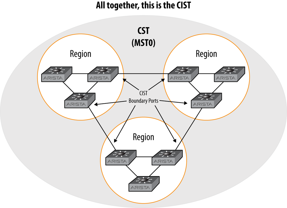
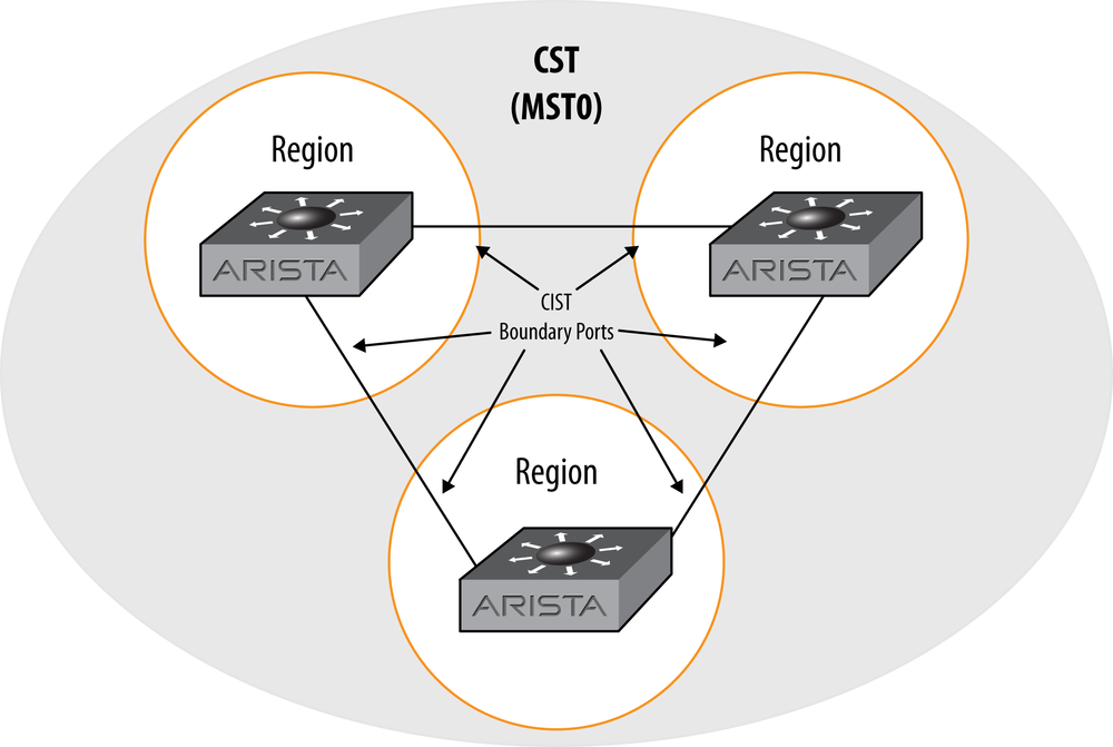
If you’re familiar with BGP, each region is sort of like a BGP confederation, in that the region behaves like a single bridge in relation to other regions. Since each region has its own root, the topology within the region is distinct from the topology outside of the region. The topology between regions is distinct from the topology within regions. I like to call each of the regions a super switch when teaching people who are not familiar with BGP, which is completely inaccurate, but it gets the point across. The way the CST (MST0) sees the regions shown in Figure 13-6 is represented in Figure 13-7.
As I warned earlier, it’s easy to get switches configured into their own region without realizing it. When I design an MST-based network, I like to make each instance into its own region where possible, because this makes it easier for junior engineers to visualize what’s going on. Since the regions aren’t really identified in the output of the spanning tree commands, I like to separate them using instances. Now, this may not be possible in your network, especially if you’re a fan of balancing even/odd VLANs between core switches. Still, so long as the instance VLAN mapping remains consistent, and the configuration names and revisions match, then getting your regions mapped should be relatively straightforward. That said, here’s some advice that will help when using MST:
As Einstein said, make it as simple as possible, but no simpler. The more complicated you make your MST design, the harder it will be to understand.
There aren’t really benefits to running multiple regions unless you have a very complicated network. Where I have physically disparate networks in the same building, I’ll put them into different instance numbers, so that if they ever do get connected, they will form boundary ports and won’t just extend the region.
One of the ways I like to use regions is when layer-2 networks span physical buildings. I have a client that has VLANs spanning four buildings. By limiting the interbuilding connectivity, and making each building its own region, then the building itself becomes a super switch, and any improper new links will only affect the CST topology, and not the topology within the building.
If your network is small, consider a single MST instance with a single region. Though you shouldn’t keep everything in MST0, placing all your switches and all your VLANs into MST1 isn’t necessarily a bad thing.
This little tip is one of those things that people seem to learn the hard way. Let’s see if I can help you avoid the pain and misery that can occur when you inadvertently split VLANs with MST. Don’t ask me how I know about the pain and suffering. You’ll just have to take my word on that part.
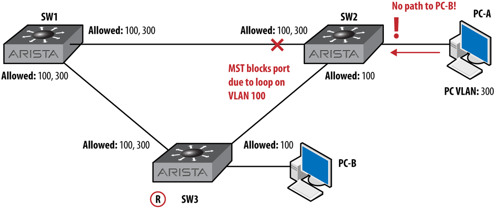
In Figure 13-8, I’ve drawn a simple network that looks a lot like the one I’ve used previously in this chapter. In this network, there are three switches and two VLANs. PC-A, connected to SW2, is on VLAN 300, as is PC-B, which is on SW3. The links between the switches are trunks, but the link between SW2 and SW3 does not have VLAN 300 allowed.
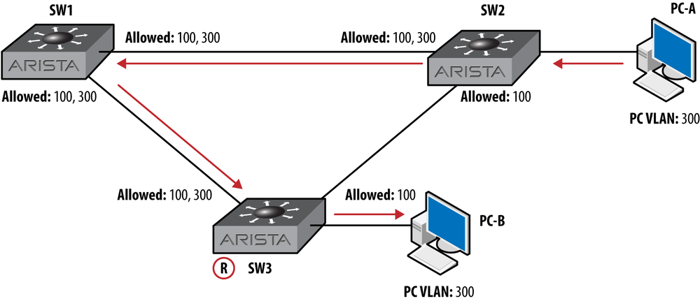
The point of this lesson is to remember that MST does not care about VLANs, only instances. In this network, with PVST, VLAN 300 has no loop, but VLAN 100 does, so only VLAN 100 has a blocked port. That’s OK, because there is an alternate path, and all traffic can flow on all VLANs.
Figure 13-9 shows the same network with MST running on all switches. In this example, all switches are configured properly in MST1, and they are all in the same region. Since MST doesn’t care about VLANs and only loops within regions, the link between SW1 and SW2 will be blocked, which will cause PC-A to no longer have a path to PC-B. We have a special term for this in networking: it’s called bad.
There are a couple of ways to prevent this from happening. If all of these switches truly belong in the same region, then you could stop pruning VLAN 300 from the SW2–SW3 link. Pruning can be a great way to limit traffic on links, but in this network, I doubt that VLAN 300 really needed to be pruned in the first place. That’s of little comfort, though, when it worked before you converted to MST and now it doesn’t. It turns out that some executives are really sensitive about things like this.
Another way to resolve this problem is to put VLAN 100 in one MST instance, and VLAN 300 in another. Then, the VLAN 100 instance would block the SW1–SW2 link as shown, but the VLAN 300 instance would have no ports blocked, since that instance would not see a loop. Watch out for overly complex instance VLAN maps though, since making things complicated leads to switches in different regions when you’re not careful about matching MST configurations.
When MLAG is configured, one of the switches in the MLAG cluster will become the primary switch. The MLAG primary switch will do all of the STP processing, and changes to the secondary will have no effect. There is a pretty big caveat to that statement though, and that is that changes made to the secondary MLAG switch’s STP configuration will be accepted to the running-config, but they will not take effect unless, that is, the primary MLAG switch relinquishes its role as primary, at which point, all the commands entered on the secondary (now primary) switch will suddenly become active. What’s worse, you may not see this coming. Allow me to demonstrate.
I have two switches, SW1 and SW2, configured as an MLAG pair. I have STP configured, and SW1 is the root, but it won because of a priority tie. SW2 is also the MLAG primary switch. I’ll be working on SW1, so here’s proof that it’s the MLAG secondary switch:
SW1(config)#sho mlag det | grep state
state                           :               Active
State                           :            secondary
State changes                   :                    1
Last state change time          :          1:01:44 ago
P2p mount state changes         :                    1
Now, I’ll go into SW1 and start mucking with STP. I want to make the priority lower to force it to be the root:
SW1(config)#spanning-tree mst 1 root primaryWhen I make this change, nothing happens. Frustrated because my change has no effect, I decide to hardcode the priority:
SW1(config)#spanning-tree mst 1 priority 8192Again, nothing happens. Beyond frustrated, I issue the show spanning-tree mst 1 command to see what’s
up:
SW1(config)#sho spanning-tree mst 1
MST1
  Spanning tree enabled protocol mstp
  Root ID    Priority    32769
             Address     021c.7313.35ec
             This bridge is the root

  Bridge ID  Priority    32769  (priority 32768 sys-id-ext 1)
             Address     021c.7313.35ec
             Hello Time  2.000 sec Max Age 20 sec Forward Delay 15 sec

Interface        Role       State      Cost      Prio.Nbr Type
---------------- ---------- ---------- --------- -------- ------------
Et20             designated forwarding 2000      128.220  P2p
Et21             designated forwarding 2000      128.221  P2p
PEt20            designated forwarding 2000      128.20   P2p
PEt21            designated forwarding 2000      128.21   P2p
PPo10            designated forwarding 1999      128.101  P2p
Po10             designated forwarding 2000      128.102  P2p
If I hardcoded the priority to 8,192, why isn’t it showing my change? Disgusted and impatient, I rebooted the other switch, because that was so much easier than reading the documentation. Imagine though, that instead of me rebooting a switch in a lab that these switches are in production, and after my changes didn’t work, I gave up and walked away. You know, because that’s what happens in real data centers. Anyway, for whatever reason, at this point, SW2 (the primary MLAG switch) reboots. As soon as it goes down, I get the normal MLAG message on SW1’s console:
SW1(config)#
May 22 15:34:05 SW1 Mlag: %FWK-3-SOCKET_CLOSE_REMOTE: Connection
to Mlag (pid:2328) at tbt://20.20.20.2:4432/ closed by peer (EOF)
May 22 15:34:05 SW1 Mlag: %FWK-3-SELOR_PEER_CLOSED: Peer closed
socket connection. (tbt://20.20.20.2:4432/-in)(Mlag (pid:2328))
All of a sudden and without any real warning, SW1 is the root bridge for MST1 with a priority of 8,192:
SW1(config)#sho spanning-tree mst1
MST1
  Spanning tree enabled protocol mstp
  Root ID    Priority    8193
             Address     021c.7313.35ec
             This bridge is the root

  Bridge ID  Priority     8193  (priority 8192 sys-id-ext 1)
             Address     021c.7313.35ec
             Hello Time  2.000 sec Max Age 20 sec Forward Delay 15 sec

Interface        Role       State      Cost      Prio.Nbr Type
---------------- ---------- ---------- --------- -------- ------------
Et20             designated discarding 2000      128.20   P2p
Et21             designated discarding 2000      128.21   P2p
Po10             designated discarding 1999      128.102  P2p
This happened because this switch is now the MLAG primary, as
evidenced by the output of show mlag detail |
grep state:
SW1(config)#sho mlag det | grep state
state               :              Active
State                           :                primary
State changes                   :                      3
Last state change time          :            0:19:54 ago
P2p mount state changes         :                      3
Warning
The fact that this happens like this is not really a problem; it is functioning by design. The problem is that when configuring STP on the secondary MLAG switch, there are no warnings that your changes are being saved, and no warnings that any changes made will take effect when and if this switch becomes the primary. Be very careful about making changes to STP when configuring the MLAG secondary switch.
This behavior was recorded on switches running EOS 4.9.3.2. When I told Arista about it, they agreed that there should be some sort of warning, so I wouldn’t be surprised if this gets safer in a future release.
One last note, because this comes up a lot: no, you should not disable STP if you’re using MLAG (or any vendor’s MLAG technology). Ask any networking consultant if he’s heard of a spanning tree event being caused by someone bringing in a home office switch and connecting it where it didn’t belong. I know I’ve seen that more than once. Hell, I had a client who refused to run more than two Ethernet runs to each cube, insisting that should anyone need more ports, they could just bring in a switch from home. This is an outage waiting to happen, and STP is the last line of defense against the loop-inducing server guy who needs 14 ports on his desk. Do yourself a favor and outlaw switches on (or under) desks. And keep STP running, because when you outlaw desktop switches, only outlaws will have desktop switches…or something.