
First hop redundancy is the ability for one or more devices to share the same IP address in order to provide multidevice resiliency in default gateway scenarios (though they can be nondefault gateways, too). Usually, this involves one device owning the IP address while other devices stand by, ready to assume control of the address should the owner fail. This is not always the case, however, as we’ll see.
Cisco’s proprietary Hot Standby Router Protocol (HSRP) is probably what most Cisco shops are using to accomplish this, but outside of the Cisco world the Virtual Router Redundancy Protocol (VRRP) is the standard. This is likely due to the fact that it is an open source protocol, and therefore supported by multiple vendors. Arista’s EOS supports VRRP, but also introduces an interesting new feature called Layer-3 Anycast Gateway, or Virtual Address Resolution Protocol (VARP). In this chapter, we’ll take a look at both VRRP and VARP, including configuration examples and reasons why you might choose one solution over the other.
If all you’ve ever used is Cisco’s HSRP, then don’t worry, because VRRP is pretty much the same thing. In fact, it’s so similar that Cisco complained vigorously when the RFC for VRRP was announced. VRRP is defined in RFCs 2338, 3768, and 5798, while Cisco’s HSRP is defined in RFC 2281. The RFC for HSRP states that:
2  Conditions of Use

   US Patent number 5,473,599 [2], assigned to Cisco Systems, Inc. may
   be applicable to HSRP. If an implementation requires the use of any
   claims of patent no. 5,473,599, Cisco will license such claims on
   reasonable, nondiscriminatory terms for use in practicing the
   standard.  More specifically, such license will be available for a
   one-time, paid up fee.
Cisco complained to the Internet Engineering Task Force (IETF) with the following:
In Cisco’s assessment, the VRRP proposal does not represent any significantly different functionality from that available with HSRP and also implementation of draft-ietf-vrrp-spec-06.txt would likely infringe on Cisco’s patent #5,473,599. When Cisco originally learned of the VRRP proposal, the Hot Standby Router Protocol was then promptly offered for standardization with the understanding that, if approved, licenses for HSRP would be made available on reasonable, nondiscriminatory terms for implementation of the protocol.
The full text of Cisco’s response to the VRRP RFC is available online. My point in this little legal tangent is that VRRP is very similar to HSRP, so it’s nothing to be afraid of. But surely, there must be differences, or Cisco would be suing every vendor that uses VRRP. Let’s take a look at how to configure VRRP, and we’ll see how things differ as we go. I’ll be making comparisons to Cisco’s HSRP, since most of the people I’ve taught Arista topics to come from a Cisco background.
First, we need to get some terms straight. In VRRP, a virtual router is one or more devices configured as a sort of cluster, wherein one of the devices is the master router, and the rest are backup routers. This is a bit different than HSRP, in that HSRP can have only one active router, and one standby router. Any other devices configured in the same HSRP group are in a listening state. When an HSRP event occurs that causes both the active and backup routers to fail, a new election takes place among the listening routers.
With VRRP, multiple routers may be configured to be in the virtual router, and they’ll all be backup routers if not elected as the master.
Note
The term router is used accurately, even though we’re talking about switches in this book, since VRRP can only be configured on an L3 interface.
A VRRP virtual router is defined by “A virtual router identifier (VRID) and a set of IP addresses” according to RFC 2338. In other words, in order for routers to become part of a virtual router, they must agree on the VRID and IP addresses. The VRID is the group number (just like HSRP), and the IP addresses are the VIPs to be shared.
Note
A quick note about Arista’s implementation of VRRP is in order. In many vendors’ implementations, the configured IP address of the interface can be used as the VIP. According to the RFC, this is an option, and it looks like Arista did not opt to include this option, at least up to EOS version 4.9.3.2.
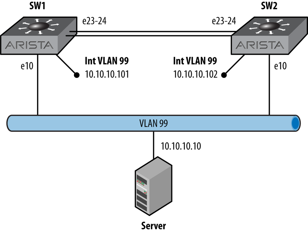
So let’s get started by looking at a simple network, as shown in Figure 14-1. There are two switches, both connected to VLAN 99. Each switch has a Switch Virtual Interface (SVI) configured and IP routing enabled. The server will be configured to use these switches as its default gateway.
Let’s start with the existing configuration of SW1:
SW1(config)#sho run int vlan 99
interface Vlan99
   ip address 10.10.10.101/24
And here’s SW2:
SW2(config)#sho run int vlan 99
interface Vlan99
   ip address 10.10.10.102/24
It would be difficult to get much simpler than that! So let’s add the simplest of VRRP configs. Naturally, we’ll need to get into interface configuration mode:
SW1(config)#int vlan 99
SW1(config-if-Vl99)#
In its simplest form, VRRP just needs a virtual router group number, and a group IP address:
SW1(config-if-Vl99)#vrrp 99 ip 10.10.10.100The group number can be any number inclusive of 1 to 255. According to the Arista configuration guide (section 3.1.1), Two virtual routers cannot be assigned the same VRID, even when they are on different VLANs. A virtual router’s scope is restricted to a single LAN. This can seem misleading, but I think the RFC has the answer:
   However, there is no restriction against reusing a VRID with a
   different address mapping on different LANs. The scope of each
   virtual router is restricted to a single LAN.
In short, you can have the same group number on multiple interfaces, but you cannot have the same group number/IP address combination on two interfaces, which makes perfect sense, since you can’t really have the same IP network on two interfaces anyway.
At this point, VRRP is active, and the status can be viewed
with the show vrrp command:
SW1(config-if-Vl99)#sho vrrp
Vlan99 - Group 99
  State is Master
  Virtual IP address is 10.10.10.100
  Virtual MAC address is 0000.5e00.0163
  Advertisement interval is 1.000s
  Preemption is enabled
  Preemption delay is 0.000s
  Preemption reload delay is 0.000s
  Priority is 100
  Master Router is 10.10.10.101 (local), priority is 100
  Master Advertisement interval is 1.000s
  Master Down interval is 3.609s
Since this is all it takes to get a virtual router configured, many people prefer to add the IP address last if they will be altering any of the default values. If you’ve got devices out there looking for this IP address, it just became available, and when we go in and muck with the default values, the status of the new IP may change. Speaking of defaults, let’s take a look at them from the previous output. Without configuring anything, the switch has become the master. That makes sense, since there are no other switches participating yet. Note that the advertisement interval is one second, and that preemption is enabled. By comparison, HSRP sends hello packets every three seconds, which raises another important difference between the two protocols.
With HSRP, both the active and standby routers send hello packets, while any routers configured to listen just, well, listen. With VRRP, only the active router sends out advertisements; the backup routers all just listen.
Preemption is enabled by default with VRRP, which I think is great
because, honestly, I can’t remember the last time I configured HSRP
without preemption enabled. Still, if you’d like to disable preemption,
you can do so with the no vrrp
group-number preempt
command:
SW1(config-if-Vl99)#no vrrp 99 preemptPreemption can also be delayed with a couple of interesting
options shown by using the question mark after the delay keyword:
SW1(config-if-Vl99)#vrrp 99 preempt delay ?
  minimum  Specifies the minimum delay period in seconds that causes
           the local router to postpone taking over the active role.
           The range is from 0 to 3600 seconds (1 hour). The default
           is 0 second (no delay).

  reload   Specifies the preemption delay, in seconds, after a reload
           only. This delay period applies only to the first
           interface-up event after the router has reloaded.
  <cr>
In order to set the minimum delay for 30 seconds and the reload delay for 60 seconds, you can combine both into the following single command:
SW1(config-if-Vl99)#vrrp 99 preempt delay minimum 30 reload 60The VRRP master router sends out advertisements every one second
by default. To change it, use the vrrp group-number
timers advertise
seconds command. Here, I’ve changed the
default to 10 seconds:
SW1(config-if-Vl99)#vrrp 99 timers advertise 10Now that I’ve messed with all the defaults, let’s take a look at
the output of show vrrp again:
SW1(config-if-Vl99)#sho vrrp
Vlan99 - Group 99
  State is Master
  Virtual IP address is 10.10.10.100
  Virtual MAC address is 0000.5e00.0163
  Advertisement interval is 10.000s
  Preemption is disabled
  Preemption delay is 30.000s
  Preemption reload delay is 60.000s
  Priority is 100
  Master Router is 10.10.10.101 (local), priority is 100
  Master Advertisement interval is 10.000s
  Master Down interval is 30.609s
OK, that was fun, but let’s put all those values back to their defaults so we can move on:
SW2(config-if-Vl99)#vrrp 99 preemptSW2(config-if-Vl99)#default vrrp 99 timers advertiseSW1(config-if-Vl99)#default vrrp 99 preempt delay
Let’s make sure that everything is back to normal:
SW1(config-if-Vl99)#sho vrrp
Vlan99 - Group 99
  State is Master
  Virtual IP address is 10.10.10.100
  Virtual MAC address is 0000.5e00.0163
  Advertisement interval is 1.000s
  Preemption is enabled
  Preemption delay is 0.000s
  Preemption reload delay is 0.000s
  Priority is 100
  Master Router is 10.10.10.101 (local), priority is 100
  Master Advertisement interval is 1.000s
  Master Down interval is 3.609s  Master Advertisement interval is 1.000s
  Master Down interval is 3.609s
Now let’s see what happens when we add SW2 to the mix with all the defaults left alone:
SW2(config)#int vlan 99SW2(config-if-Vl99)#vrrp 99 ip 10.10.10.100
Let’s see what SW2 thinks about our new VRRP config:
SW2(config-if-Vl99)#sho vrrp
Vlan99 - Group 99
State is Backup
Virtual IP address is 10.10.10.100
Virtual MAC address is 0000.5e00.0163
Advertisement interval is 1.000s
Preemption is enabled
Preemption delay is 0.000s
Preemption reload delay is 0.000s
Priority is 100
Master Router is 10.10.10.101, priority is 100
Master Advertisement interval is 1.000s
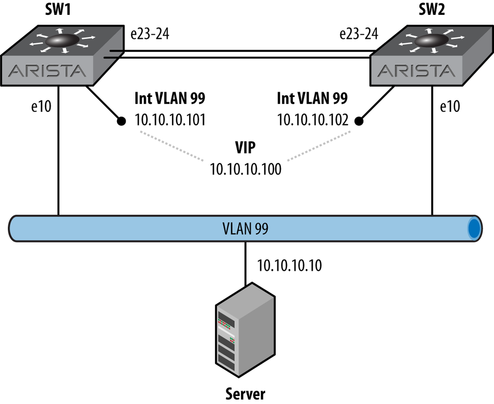
Master Down interval is 3.609sLooks good, and everything has the same default values. The new VRRP-enabled network is shown in Figure 14-2.
So what made SW2 decide to become the backup router? It became the backup because a master already existed and that master had the same priority as SW2. Here’s what the RFC says on the subject:
The protocol should ensure after Master election that no state
transition is triggered by any Backup router of equal or lower
preference as long as the Master continues to function properly.
If I were to pull off all the configurations and configure SW2 first, it would become the master, and when I configured SW1, then SW1 would become the backup. This can be different behavior than that exhibited by HSRP. If two routers are both configured in the same group, on the same VLAN, with the same VIP, they will negotiate who will become the master, and a new master may be chosen (depending on the version of code; this behavior has changed over time).
I like to have a little more control over which switch becomes the master router, so I’ll assign a priority to the VRRP group. Since SW2 is currently the backup, let’s configure it with a higher priority and see what happens. The default priority is 100. The priority value can be any integer in the range of 1 to 254, so let’s make SW2 have a priority of 105:
SW2(config-if-Vl99)#vrrp 99 priority 105Note
Higher priorities are better in VRRP. Well, who’s to say what better really means? I suppose that I could say that higher priorities are more desirable, but that makes me think that the master routers should be prettier. Instead, I’ll write that the router with the highest priority will become the master router, and leave it at that. Also, a priority of 255 indicates that the interface IP is the VIP, which is why doing so will force the router to become the master. Only you can’t do that in EOS, so never mind.
The switch quickly becomes the master since it has a higher priority than SW1:
SW2(config-if-Vl99)#sho vrrp
Vlan99 - Group 99
  State is Master
  Virtual IP address is 10.10.10.100
  Virtual MAC address is 0000.5e00.0163
  Advertisement interval is 1.000s
  Preemption is enabled
  Preemption delay is 0.000s
  Preemption reload delay is 0.000s
  Priority is 105
  Master Router is 10.10.10.102 (local), priority is 105
  Master Advertisement interval is 1.000s
  Master Down interval is 3.590s
So now that we’ve got SW2 set with a higher priority, let’s see how preemption works. I’ll just shut down the SVI for VLAN 99 on SW2:
SW2(config-if-Vl99)#shutIn short order, SW1 becomes the master router:
SW1#sho vrrp
Vlan99 - Group 99
  State is Master
  Virtual IP address is 10.10.10.100
  Virtual MAC address is 0000.5e00.0163
  Advertisement interval is 1.000s
  Preemption is enabled
  Preemption delay is 0.000s
  Preemption reload delay is 0.000s
  Priority is 100
  Master Router is 10.10.10.101 (local), priority is 100
  Master Advertisement interval is 1.000s
  Master Down interval is 3.609s
Remember when we added SW2, it became the backup because SW1 was already the master, and the priorities were the same? This time, when SW2 starts advertising itself as a master with a priority of 105, it should immediately take over master duty:
SW2(config-if-Vl99)#no shutSW1 gives up its role as master since a better master is available:
SW1#sho vrrp
Vlan99 - Group 99
  State is Backup
  Virtual IP address is 10.10.10.100
  Virtual MAC address is 0000.5e00.0163
  Advertisement interval is 1.000s
  Preemption is enabled
  Preemption delay is 0.000s
  Preemption reload delay is 0.000s
  Priority is 100
  Master Router is 10.10.10.102, priority is 105
  Master Advertisement interval is 1.000s
  Master Down interval is 3.609s
Technically, the router preempted when we first changed the priority, but I just wanted to show that failing the new master and then bringing it back online would force another preemption.
Most VRRP implementations I’ve used allow the VRRP VIP to be the same as the physical interface’s IP address on the master router. In fact, the RFC specifically mentions that using the physical IP address of a router will automatically make it the master. As of EOS 4.9.3.2, the ability to use the physical interface’s IP address as the VIP is not supported, and will result in an error:
SW1(config-if-Vl99)#vrrp 99 ip 10.10.10.101
% Address 10.10.10.101 is already assigned to interface Vlan99
One of the cool features of VRRP that I rarely see used is the ability to serve multiple IP addresses within the group:
SW2(config-if-Vl99)#vrrp 99 ip 10.10.10.99 secondarySW2(config-if-Vl99)#vrrp 99 ip 10.10.10.98 secondary
And here’s the result:
SW2(config-if-Vl99)#sho vrrp
Vlan99 - Group 99
  State is Master
  Virtual IP address is 10.10.10.100
    Secondary Virtual IP address is 10.10.10.98
    Secondary Virtual IP address is 10.10.10.99
  Virtual MAC address is 0000.5e00.0163
  Advertisement interval is 1.000s
  Preemption is enabled
  Preemption delay is 0.000s
  Preemption reload delay is 0.000s
  Priority is 105
  Master Router is 10.10.10.102 (local), priority is 105
  Master Advertisement interval is 1.000s
  Master Down interval is 3.590s
Of course, any such configuration should be done on all routers within the group. Another allowable configuration involves multiple groups within the same interface, with each group providing different VIPs. I’ll configure VRRP group 66 on both switches, serving the IP address 10.10.10.66. Here’s SW1:
SW1(config-if-Vl99)#vrrp 66 ip 10.10.10.66SW1(config-if-Vl99)#vrrp 66 priority 105
And here’s SW2:
SW2(config-if-Vl99)#vrrp 66 ip 10.10.10.66While I’ve configured SW2 to have a higher priority in the VRRP 99 group, I configured VRRP group 66 to have the higher priority on SW1. Remember, this is all within the same VLAN (99). Let’s see what the status looks like on SW1 now:
SW1(config-if-Vl99)#sho vrrp
Vlan99 - Group 66
  State is Master
  Virtual IP address is 10.10.10.66
  Virtual MAC address is 0000.5e00.0142
  Advertisement interval is 1.000s
  Preemption is enabled
  Preemption delay is 0.000s
  Preemption reload delay is 0.000s
  Priority is 105
  Master Router is 10.10.10.101 (local), priority is 105
  Master Advertisement interval is 1.000s
  Master Down interval is 3.590s

Vlan99 - Group 99
  State is Backup
  Virtual IP address is 10.10.10.100
    Secondary Virtual IP address is 10.10.10.98
    Secondary Virtual IP address is 10.10.10.99
  Virtual MAC address is 0000.5e00.0163
  Advertisement interval is 1.000s
  Preemption is enabled
  Preemption delay is 0.000s
  Preemption reload delay is 0.000s
  Priority is 100
  Master Router is 10.10.10.102, priority is 105
  Master Advertisement interval is 1.000s
  Master Down interval is 3.609s
With this VRRP configuration, the IP address 10.10.10.66 is currently being served by SW1, while the IP addresses 10.10.10.98 to 100 are being served by SW2. In VRRP terms, SW1 is the master router for group 66, and SW2 is the master router for group 99.
Note
I’m not a big fan of doing this type of balancing, but you could use it to have some of your servers use one router while some of your servers use another, all while being on the same VLAN. I call this sort of design manual load balancing, and I don’t recommend it because, invariably, someone doesn’t keep track of what server is assigned where, then one router gets overwhelmed or some other problem occurs, and then it’s your fault. Wherever possible, I try not to make things my fault, unless of course they’re good things, in which case I’ll absolutely take the blame.
VRRP can be secured using clear text or encrypted passwords by
using the vrrp
group-id authentication command. Options for
encryptions include text and ietf-md5. Here’s how a plain text password
would be configured:
SW1(config-if-Vl99)#vrrp 99 auth text ILikePieWhen using a clear-text password, the password is clearly visible, which is likely why they call it clear text. It is also the reason why you shouldn’t use it:
SW1(config-if-Vl99)#sho vrrp int vlan 99 | grep Auth
  Authentication text, string "ILikePie"
If you’re going to bother using passwords, then do yourself a
favor and encrypt them with the ietf-md5
key-string string option:
SW1(config-if-Vl99)#vrrp 99 auth ietf-md5 key-string ILikePieWhen using MD5 passwords, the password is not shown in the status output, or in the running-config:
SW1(config-if-Vl99)#sho vrrp int vlan 99 | grep Auth
  Authentication MD5, key-string
The last thing to cover regarding VRRP is the ability to track other interfaces. While I think this has more value on WAN routers where serial links are likely to fail in colorful and interesting ways, the ability to track another interface is always welcome, so let’s see how it works. First, we’ll start with a baseline VRRP configuration. Here’s the configuration for SW2, which is back to having only one group and a priority of 105:
SW2(config-if-Vl99)#sho run int vlan 99
interface Vlan99
   ip address 10.10.10.102/24
   vrrp 99 priority 105
   vrrp 99 ip 10.10.10.100
Here’s the status for this switch:
SW2(config)#sho vrrp
Vlan99 - Group 99
  State is Master
  Virtual IP address is 10.10.10.100
  Virtual MAC address is 0000.5e00.0163
  Advertisement interval is 1.000s
  Preemption is enabled
  Preemption delay is 0.000s
  Preemption reload delay is 0.000s
  Priority is 105
  Master Router is 10.10.10.102 (local), priority is 105
  Master Advertisement interval is 1.000s
  Master Down interval is 3.590s
The first step in tracking another interface is to create an object to track. Currently, as of EOS version 4.9.3.2, the only objects that can be created are interface line protocol objects. I can see that Arista, being the forward thinkers that they are, have left the doors open for all sorts of objects in the future. I imagine that I’d be able to track IP routes, ARP entries, MAC-table entries, and all sorts of wonderful things, but for now, let’s ignore my rambling daydreams and focus on the type we have available to us.
To create an object, you must specify an object name. I’m going to call mine GAD, because I’m the damn writer and I like seeing my initials in lights…or something. After specifying the object name, append the object type to be tracked. Judicious use of tab completion and the question mark will show you that this is the only choice to be made, unless you’d like to use your own initials, in which case I say, fine be that way:
SW2(config)#track GAD int e10 line-protocolOnce the object is created, you can reference it with the vrrp group-number
track
object-name interface command. There are two
options: decrement and
shutdown. Decrement will lower the priority by the
specified amount, and shutdown will
disable the VRRP group entirely. For this example, I’ll decrement the
priority by 10:
SW2(config)#int vlan 99SW2(config-if-Vl99)#vrrp 99 track GAD decrement 10
With this track configured, should interface e10 go down, the priority for VRRP group 99 will drop 10 points, from 105 down to 95, which would make it five less than SW1’s default priority of 100. Let’s shut down interface e10 and see what happens:
SW2(config-if-Vl99)#int e10SW2(config-if-Et10)#shut
With that done, let’s see what VRRP looks like on SW2:
SW2(config-if-Et10)#sho vrrp
Vlan99 - Group 99
  State is Backup
  Virtual IP address is 10.10.10.100
  Virtual MAC address is 0000.5e00.0163
  Advertisement interval is 1.000s
  Preemption is enabled
  Preemption delay is 0.000s
  Preemption reload delay is 0.000s
  Priority is 95
  Master Router is 10.10.10.101, priority is 100
  Master Advertisement interval is 1.000s
Master Down interval is 3.629sVRRP has some cool features, as we’ve seen, but for some
reason, I’m tickled by the idea that a VRRP group can be shut down like
an interface can. To do so, just use the vrrp group-id
shut interface command:
SW2(config-if-Vl99)#vrrp 99 shutTo bring it back up, negate the command:
SW2(config-if-Vl99)#no vrrp 99 shutWe’ve already seen the results of the show vrrp command, but with many groups
configured, it can get unwieldy. The command can be modified with the
interface keyword, which is useful,
but for my money the show vrrp brief
command is the go-to command in busy environments:
SW1#sho vrrp brief
Port       Group Prio Time   Own  State    MaIp           GrIp
Vlan99     66    105  3589        Master   10.10.10.101   10.10.10.66
Vlan99     99    100  3609        Backup   10.10.10.102   10.10.10.100
With track objects configured, you can see them with the
show track command. This can be very
useful, especially when you have an object tracked in more than one
place:
SW2#sho track
Tracked object GAD is up
   Interface Ethernet10 line-protocol
      3 change, last change time was 1:17:30 ago
   Tracked by:
      Vlan99 vrrp instance 99
This command also has a brief modifier, but be careful because you have to spell out the word brief, or else the parser thinks you’re specifying the name of a track object:
SW2#sho track brief
Tracked object GAD is upVirtual ARP, or Layer-3 Anycast Gateway, is a feature that’s so simple, I’m amazed that no one has ever thought of it before. Put simply, multiple devices are configured to respond to ARP and GARP requests for a shared virtual IP address using a shared virtual MAC address. Seriously, that’s all it does. So what’s so great about that?
First, by the very nature of the fact that both switches in a pair respond to ARP requests for the same IP address, that means that some devices will learn the MAC address from one switch, while other devices will learn from the other switch (assuming a pair). That also means that both switches can actively receive packets destined for the IP address. This active–active behavior is something that neither VRRP nor HSRP can replicate. Not only that, but VARP is completely standards-based.
Cisco’s Gateway Load Balancing Protocol (GLBP) offers ARP load balancing, which is kind of similar at a high level, but much more complicated to configure and understand, which brings me to the second benefit. VARP takes just two lines of configuration on each switch for a single IP address, and one additional line for each additional IP to be shared. There are no options, no timers, and no additional features to worry about. It just works.
Third, because packets that are received on a VARP address are forwarded to the next hop destination on the same switch on which they were received (assuming IP routing is enabled and properly configured), these packets never need to traverse the interswitch link, thus reducing traffic latency, not to mention load on switches that don’t really need to carry the traffic in the first place.
This is accomplished by configuring a virtual MAC address globally on each switch. The switches will respond to ARP requests for each of the IP addresses to be shared with this configured MAC address, regardless of the VLAN or interface on which the request is heard.
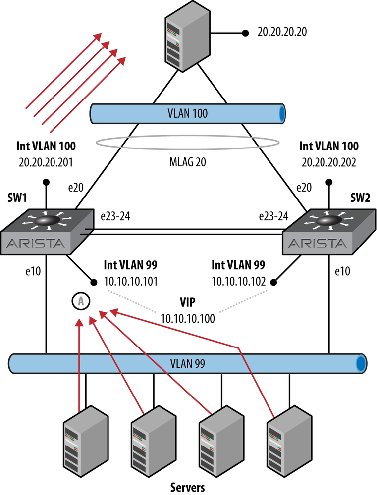
Let’s take a look at how VARP might be used. First, let’s take a look at VRRP in use on a sample network. In Figure 14-3, there are four servers on VLAN 99, all configured to use the VRRP VIP of 10.10.10.100 as their default gateways. When they communicate with the server at 20.20.20.20, the packets all go to the active router, which is SW1, where they are forwarded from the SVI on VLAN 100. Since MLAG forwards packets from the switch on which they were received, all of these packets will be forwarded from SW1’s e10 interface to the server at 20.20.20.20.
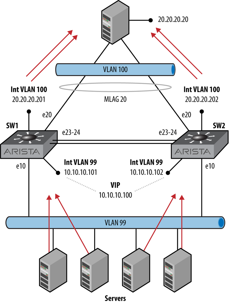
Now, let’s compare that flow with the traffic flow for the same network using VARP. In Figure 14-4, since both switches have responded to the ARP requests for the default gateway of 10.10.10.100, both switches will receive packets from a random sampling of the servers that sent the ARP requests.
Note
Though Figure 14-4 shows a nice, even distribution of servers, this is due to my neurosis that prevents me from crossing lines in drawings unless absolutely necessary. VARP does not weigh, distribute, or otherwise manage load in any way. The servers just believe whatever ARP response they received first, even if more than one gateway responds (see RFC 1027 if you don’t believe me).
Note also that should a packet arrive on a switch other than the active router, then the packet will be forwarded over the peer-link in order to get to the active router, after which it will then be forwarded at layer-3.
Since MLAG forwards packets out the same switch wherever possible, the packets are then distributed over both switches, thus better utilizing the switches, the uplinks, and the network in general.
One thing to remember about VARP is that traffic is never sourced from the virtual address. That means that the VIP cannot be used in routing, nor can it be used as a source address for protocols or features that support changing the source interface or address.
If you’re lucky enough to have a lab full of Arista switches, you should clear all the VRRP stuff that we worked on earlier in this chapter. The configuration for the VLAN 99 SVI on SW1 should look like this to start:
SW1(config)#sho run int vlan 99
interface Vlan99
   ip address 10.10.10.101/24
And here’s SW2’s fresh VLAN 99 SVI configuration:
SW2(config)#sho run int vlan 99
interface Vlan99
   ip address 10.10.10.102/24
The first step is to configure the MAC address that our VIPs will use. This MAC will be used for every VIP we create on every VLAN, so make it count. I’ve blatantly stolen this MAC address from the Arista article on VARP because I was too lazy to look up the rules for making up MAC addresses.
Note
What can I say? Writing a book involves looking up a lot of things, and I just couldn’t bear to look up one…more…damn…thing.
SW1(config)#ip virtual-router mac-address 00:1c:73:00:00:99If you don’t do this step, then the next step will fail. The next step is to configure a VIP on an interface, and if it fails, don’t say I didn’t warn you:
SW1(config)#int vlan 99SW1(config-if-Vl99)#ip virtual-router address 10.10.10.100
Warning
VARP cannot be configured on routed Ethernet interfaces, including the management interfaces. It is only configurable on VLAN interfaces. While the Arista Configuration Guide doesn’t specifically say that it won’t work on Ethernet interfaces, to be fair, it only mentions VLAN interfaces in the VARP section. If you need first hop redundancy on physical interfaces, you’ll need to use VRRP.
That’s it! The switch is now responding to ARP requests for the VIP 10.10.10.100 with the MAC address we took so much time to research and create. Once these two steps are done, you’ll be able to ping the VIP:
SW1#ping 10.10.10.100
PING 10.10.10.100 (10.10.10.100) 72(100) bytes of data.
80 bytes from 10.10.10.100: icmp_req=1 ttl=64 time=0.062 ms
80 bytes from 10.10.10.100: icmp_req=2 ttl=64 time=0.014 ms
80 bytes from 10.10.10.100: icmp_req=3 ttl=64 time=0.011 ms
80 bytes from 10.10.10.100: icmp_req=4 ttl=64 time=0.011 ms
80 bytes from 10.10.10.100: icmp_req=5 ttl=64 time=0.011 ms

--- 10.10.10.100 ping statistics ---
5 packets transmitted, 5 received, 0% packet loss, time 0ms
rtt min/avg/max/mdev = 0.011/0.021/0.062/0.020 ma
Note
Pinging the VIP only works on EOS versions 4.8.1 and later. If you want to use VARP, you really should use a later version because the inability to ping the VIP will drive you slowly mad. Now you know how I got this way.
We can also ping the VARP address from SW2 now:
SW2#ping 10.10.10.100
PING 10.10.10.100 (10.10.10.100) 72(100) bytes of data.
80 bytes from 10.10.10.100: icmp_req=1 ttl=64 time=0.597 ms
80 bytes from 10.10.10.100: icmp_req=2 ttl=64 time=0.159 ms
80 bytes from 10.10.10.100: icmp_req=3 ttl=64 time=0.153 ms
80 bytes from 10.10.10.100: icmp_req=4 ttl=64 time=0.102 ms
80 bytes from 10.10.10.100: icmp_req=5 ttl=64 time=0.153 ms

--- 10.10.10.100 ping statistics ---
5 packets transmitted, 5 received, 0% packet loss, time 2ms
rtt min/avg/max/mdev = 0.102/0.232/0.597/0.184 ms
Now we’ll configure the virtual router MAC address on SW2. It should be the same as the MAC address configured on SW1:
SW2(config)#ip virtual-router mac-address 00:1c:73:00:00:99At this point, you will not be able to ping the VARP address because you’ve configured the MAC address in VARP but not entered an IP. This will override the other switch’s ARP information in the local ARP cache. Let’s take a look:
SW2(config)#sho arp
Address         Age (min)  Hardware Addr   Interface
10.10.10.5              0  000c.29a4.b705  Vlan99, Port-Channel20
10.10.10.100            0  001c.7300.0099  Vlan99, not learned
10.10.10.101            0  001c.7313.4ce0  Vlan99, Port-Channel1
10.10.10.103            0  001c.7317.5da2  Vlan99, Port-Channel20
20.20.20.1              0  001c.7313.4ce0  Vlan4094, not learned
The ARP entry is in the table as is plainly evident here, but ping no longer works:
SW2(config)#ping 10.10.10.100
PING 10.10.10.100 (10.10.10.100) 72(100) bytes of data.

--- 10.10.10.100 ping statistics ---
5 packets transmitted, 0 received, 100% packet loss, time 8005ms
So let’s add the virtual IP to VLAN 99 on SW2:
SW2(config)#int vlan 99SW2(config-if-Vl99)#ip virtual-router address 10.10.10.100
And now pinging the VIP works again:
SW2(config-if-Vl99)#ping 10.10.10.100
PING 10.10.10.100 (10.10.10.100) 72(100) bytes of data.
80 bytes from 10.10.10.100: icmp_req=1 ttl=64 time=0.061 ms
80 bytes from 10.10.10.100: icmp_req=2 ttl=64 time=0.014 ms
80 bytes from 10.10.10.100: icmp_req=3 ttl=64 time=0.011 ms
80 bytes from 10.10.10.100: icmp_req=4 ttl=64 time=0.012 ms
80 bytes from 10.10.10.100: icmp_req=5 ttl=64 time=0.011 ms

--- 10.10.10.100 ping statistics ---
5 packets transmitted, 5 received, 0% packet loss, time 0ms
rtt min/avg/max/mdev = 0.011/0.021/0.061/0.020 ms
Not only is this all we need for VARP to work, that’s about all that can be done. I like this feature because it’s simple, it works, it takes advantage of the way existing, open protocols work, and it’s easy to configure.
By the way, you can add more than one virtual IP address per
VLAN. To do so, just add another IP address with the ip virtual-router address
ip-address interface command. Feel free to
add as many as you’d like, up to the limit of 500 per VLAN. I’ll just
add three so you won’t have to flip through 10 pages of code. Besides,
my editor would just tell me to take them all out anyway:
SW2(config-if-Vl99)#ip virtual-router address 10.10.10.99SW2(config-if-Vl99)#ip virtual-router address 10.10.10.98SW2(config-if-Vl99)#ip virtual-router address 10.10.10.97
To see the status of your handiwork, use the show ip virtual router command, which will
show you the configured MAC address and all VIPs, along with the real IP
address and the interfaces on which they’re operating:
SW2#sho ip virtual-router
IP virtual router is configured with MAC address: 001c.7300.0099
Interface  IP Address        Virtual IP Address   Status      Protocol
Vlan99     10.10.10.102/24   10.10.10.97          up          up
Vlan99     10.10.10.102/24   10.10.10.98          up          up
Vlan99     10.10.10.102/24   10.10.10.99          up          up
Vlan99     10.10.10.102/24   10.10.10.100         up          up
Note
Even though the VIP will respond to pings on the latest versions of EOS, the VIP and configured MAC address do not show up in the ARP table, nor do they show up in Event Monitor. This is, after all, virtual ARP.
Note that if you have virtual router configured on some
interfaces, the output of show ip
virtual-router will include all L3 interfaces, even those
without a virtual router address configured. Here’s a switch with only
one interface configured with a VIP (VLAN 99). The others appear in the
output, but show a VIP of 0.0.0.0. The first entry, VLAN 100, has a
configured SVI with no IP address at all, which is why the IP address
column shows 0.0.0.0 as well. The second line is our original, single
VIP on VLAN 99, and the last line shows a VLAN with a configured IP
address, but no VIPs configured:
Arista(config)#sho ip virtual-router
IP virtual router is configured with MAC address: 00:1c:73:00:00:99
Interface  IP Address        Virtual IP Address
Vlan100    0.0.0.0           0.0.0.0
Vlan99     10.10.10.101      10.10.10.100
Vlan901    192.168.1.180     0.0.0.0
If you configure the interfaces with a virtual router address, but don’t configure the global virtual router MAC address, your virtual router won’t work, even though you might think that it should. Here’s what it looks like when starting with no VARP configuration:
SW1(config)#int vlan 99SW1(config-if-Vl99)#ip virtual-router address 10.10.10.100
It looks fine, but the status tells you it’s not. If you’re not used to configuring VARP, this can be confusing. You just configured the virtual router address, and it’s telling you that the virtual router is not configured:
SW1#sho ip virtual-router
IP virtual router is not configured
Once you add the virtual router MAC address, things get better:
SW1(config)#ip virtual-router mac-address 00:1c:73:00:00:99And now everything appears as it should:
SW1(config)#sho ip virtual-router
IP virtual router is configured with MAC address: 001c.7300.0099
Interface  IP Address        Virtual IP Address   Status     Protocol
Vlan99     10.10.10.101/24   10.10.10.100         up         up
VARP is a very cool protocol, and was one of the first things that piqued my interest when visiting Arista the first time. I encourage you to try it out if at all possible, and see how it can be used in your environment. And if you decide it’s not for you, you can always use VRRP.