
CHAPTER 12
Dimensioning a Drawing
Dimensions are the final ingredients to include with your cabin drawing. To introduce you to dimensioning, I'll follow a pattern similar to the one I used in Chapter 8, “Controlling Text in a Drawing.” You will first create a dimension style that contains the properties for the dimensions, and then you will add the dimensions themselves.
In this chapter, you will learn to
- Set up a dimension style
- Dimension the floor plan of the cabin
- Modify existing dimensions
- Set up a multileader style
- Modify existing dimension styles
Introducing Dimension Styles
Dimension styles are similar to text styles but they give you more options to control. You set them up in the same way, but many parameters control the various parts of dimensions, including the dimension text. Each dimension has several components:
- The dimension line
- Arrows or tick marks
- Extension lines
- Dimension text (see Figure 12.1)
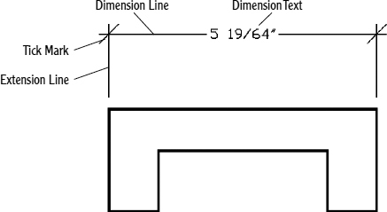
FIGURE 12.1 The parts of a dimension
An extensive set of variables stored with each drawing file controls the appearance and location of these components. You work with these variables through a series of dialog boxes designed to make setting up a dimension style as easy and trouble-free as possible. Remember that Autodesk® AutoCAD® software is designed to be used by drafters from many trades and professions, each of which has its own drafting standards. To satisfy these users' widely varied needs, AutoCAD dimensioning features have many options and settings for controlling the appearance and placement of dimensions in drawings.
Preparing for Dimensioning
Before you start setting up a dimension style, you need to make a few changes to your drawing to prepare it for dimensioning:
- Open I11A-FPLAYO.dwg(M11A-FPLAYO.dwg).
This is the cabin with hatch patterns added to all the views. If you didn't complete the “If You Would Like More Practice” section in Chapter 11, “Working with Hatches, Gradients, and Tool Palettes,” you can download the file from this book's website, www.sybex.com/go/autocad2013ner.
- Create a new layer called A-ANNO-DIMS, assign color 2 (Yellow), and make it current.
- Freeze all the remaining layers except 0, A-ANNO-TEXT, A-DECK, A-DECK-STRS, A-DOOR, A-GLAZ, A-ROOF, A-WALL, and all of the A-ELEV layers without a -PATT or -BNDY suffix.
- Set the Endpoint and Midpoint object snaps to be running.
- Set the status bar so that only the Object Snap, Dynamic Input, and Selection Cycling buttons are in their On positions.
- Click the Annotate tab. Your drawing will look like Figure 12.2.
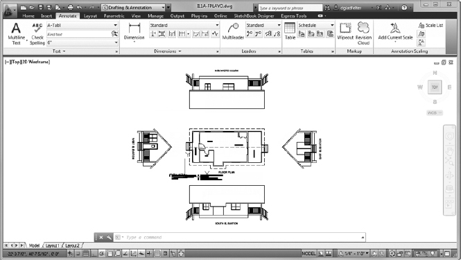
FIGURE 12.2 The cabin floor plan and elevations with the Annotate panels at the top of the drawing area
RESTORING THE STATE OF MULTIPLE LAYERS
The Layer States Manager is an incredibly powerful tool that will allow you to restore the state of a large number of layers. Although it cannot create any layers, it can save, export, and import nearly every layer property found in the Layer Properties Manager palette. By default, these are saved inside the DWG file itself, but they may also be exported to an external file. Assuming that you have employed a solid layer standard such as the NCS, you can build a library of layer states to automate tasks such as turning layers on/off, changing the color of layers, and more.
Instead of making the layer visibility changes in step 3 manually, try importing and restoring a layer state found in this chapter's set of download files:
Select Manage Layer States from the Layer States drop-down list found on the Home tab
 Layers panel.
The Layer States Manager dialog box opens.
Click the Import button in the Layer States Manager dialog box, and browse to the file 12-Start.las, found in the Chapter 12 download.
To see the file, you may need to change the Files Of Type setting to Layer States in the Import Layer State dialog box.
- Click Open to load the 12-Start.las file. The Layer State – Successful Import dialog box opens.
- Select the Restore States button from the dialog box, which will automatically apply the imported layer state.
- You'll look at the restore options in more detail in a moment, so click the Close Dialog button for now.
- The lower-right corner of the Layer States Manager dialog box has a circular button with an arrow pointing to the right. Click it to expand the dialog box.
When you are restoring layer states, it's not necessary to restore all properties associated with a layer. Instead, using the expanded Layer States Manager dialog box, you can pick the specific properties to restore by checking or unchecking the associated property.
- With the 12-Start layer state selected, click the Restore button found at the bottom of the Layer States Manager.
The Layer States Manager closes, the selected layer properties are restored (all properties in this case), and you are taken back to your drawing.
Making a New Dimension Style
Every dimension variable has a default setting, and these variables as a group constitute the default Standard dimension style. As in defining text styles, the procedure is to copy the Standard dimension style and rename the copy—in effect making a new style that is a copy of the default style. You then make changes to this new style so that it has the settings you need to dimension your drawing and save it. Follow these steps:
- Continue using I11A-FPLAYO.dwg (M11A-FPLAYO.dwg).
 Click the Dimension, Dimension Style button, the small arrow at the bottom right of the Dimensions panel on the Annotate tab to open the Dimension Style Manager dialog box (see Figure 12.3).
FIGURE 12.3 The Dimension Style Manager dialog box
At the top left in the Styles list box, you'll see Standard highlighted, or ISO-25 if your drawing is in metric.
- With Standard (ISO-25) highlighted in the Styles window, click the New button on the right side of the Dimension Style Manager dialog box.
The Create New Dimension Style dialog box shown in Figure 12.4 opens.
- In the New Style Name field, Copy of Standard (ISO-25) is highlighted. Enter A-DIMS-PLAN, but don't press
 yet.
yet.
Notice that Standard (ISO-25) is in the Start With drop-down list just below. Because it's the current dimension style in this drawing, the new dimension style you're about to define will begin as a copy of the Standard style. This is similar to the way in which new text styles are defined (as you saw in Chapter 8)—that is, by taking an existing style that is close to what you need and modifying specific elements. The Use For drop-down list allows you to choose the kinds of dimensions to which the new style will be applied. In this case, it's all dimensions, so you don't need to change this setting.
FIGURE 12.4 The Create New Dimension Style dialog box
- Click the Continue button.
The Create New Dimension Style dialog box is replaced by the New Dimension Style: A-DIMS-PLAN dialog box (see Figure 12.5). It has seven tabs containing parameters that define the dimension style. You have created a new dimension style that is a copy of the Standard style, and now you'll make the changes necessary to set up A-DIMS-PLAN to work as the main dimension style for the floor plan of the cabin.
- Verify that the Lines tab is active (on top). If it's not, click it.
You'll use the Lines tab to control the appearance of the dimension and extension lines. In most cases, the color, linetype, and lineweight should stay at their default ByBlock value, indicating that an object inherits its color from the block containing it.
- In the Extension Lines group, change the Offset From Origin setting from
 (0.63) to
  (1.25) to increase the gap between the beginning of the extension line and the object being dimensioned.
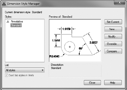
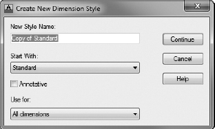
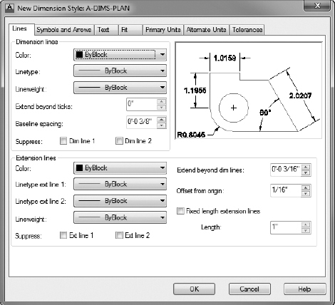
FIGURE 12.5 The New Dimension Style dialog box with A-DIMS-PLAN as the current style and Lines as the active tab
Setting Up the Symbols And Arrows Tab
The Symbols And Arrows tab has settings that control the appearance of arrowheads and other symbols related to dimensioning. Follow these steps to adjust the tab's settings:
- Click the Symbols And Arrows tab and then, in the Arrowheads group, click the down-arrow in the First drop-down list to open the list of arrowheads.
- Click the Architectural Tick option.
Architectural ticks are common for the building trades, whereas the Closed Filled option may be used in manufacturing or civil engineering drawings. This list contains options for those and several other arrowheads, dots, and so on.
The drop-down list closes, with Architectural Tick displayed in the First and Second drop-down lists. In the preview window to the right, a graphic displays samples using the new arrowhead type.
- Verify that Closed Filled is still selected from the Leader drop-down list.
- Set the Arrow Size parameter to (3.5).
After the changes, the tab should look like Figure 12.6.
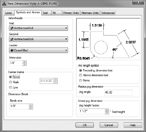
FIGURE 12.6 The Symbols And Arrows tab with the settings for the A-DIMS-PLAN style
Making Changes in the Text Tab
The settings in the Text tab control the appearance of dimension text and how it's located relative to the dimension and extension lines:
- Click the Text tab in the New Dimension Style dialog box.
Settings in three groups affect the appearance and location of dimension text.
Figure 12.7 shows the Text tab. The preview window appears in all tabs and is updated automatically as you modify settings. Look to the Text Appearance group in the upper-left corner of the dialog box, where six settings control how the text looks. You're concerned with only two of them.
-
 Click the Browse button that sits at the right end of the Text Style drop-down list to open the Text Style dialog box.
 - Set up a new text style called A-DIMS that has the following parameters:
FIGURE 12.7 The Text tab with settings for the A-DIMS-PLAN style
If you need a reminder about creating text styles, refer to Chapter 8. Apply this text style, click the Set Current button, and then close the Text Style dialog box.
- Back in the Text tab, open the Text Style drop-down list and select the new A-DIMS style from the list.
 TIP Setting the text height to 0′-0″ (0) in the Text Style dialog box allows the Text Height parameter of the dimension style to dictate the actual height of the text in the drawing. This allows many different dimension styles to use the same text style, each producing text with different heights. If you give the text a nonzero height in the Text Style dialog box, that height is always used and the Text Height parameter of the dimension style is disregarded. Typically, dimension styles are defined using a text style similar to the A-DIMS one you just created with a 0′-0″ text height.
 - Set the Text Height value to (3.5).
- Move down to the Text Placement group.
These settings determine where the text is located, vertically and horizontally, relative to the dimension line. You need to change two settings here: make sure both the Horizontal and Vertical options are set to Centered.
Some trades and professions use the Centered option for vertical text placement and the Horizontal option for text alignment.
- Move to the Text Alignment group.
The radio buttons control whether dimension text is aligned horizontally or with the direction of the dimension line. The ISO Standard option aligns text depending on whether the text can fit between the extension lines. Only one of the buttons can be active at a time. Horizontal is active, so click the Aligned With Dimension Line button.
Notice how the appearance and location of the text changes in the preview window.
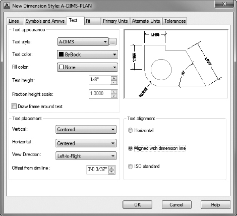
This finishes your work in this tab; the settings should look like those shown in Figure 12.7.
This dialog box has four more tabs with settings, but you'll be making changes in only two of them: Fit and Primary Units.
Working with Settings on the Fit Tab
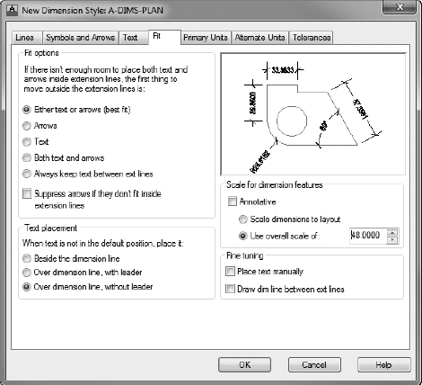
The settings on the Fit tab control the overall scale factor of the dimension style and how the text and arrowheads are placed when the extension lines are too close together for both text and arrows to fit:
- Click the Fit tab in the New Dimension Style dialog box. Figure 12.8 shows the Fit tab as you'll set it.
For your own work, you might have to experiment with the settings on this tab.
- In the upper-left corner, in the Fit Options group, verify that the Either Text Or Arrows (Best Fit) radio button is selected.
I recommend you keep this setting unchanged unless you have a specific need or the Best Fit option places your dimensions/text incorrectly.
- In the Text Placement group, click the Over Dimension Line, Without Leader radio button.
- Move to the Scale For Dimension Features group.
Be sure the Use Overall Scale Of radio button is active.
FIGURE 12.8 The new settings in the Fit tab
- Set the scale to 48 (50).
- In the Fine Tuning group, verify that the Draw Dim Line Between Ext Lines option is unchecked.
The settings on the Fit tab should look like those in Figure 12.8.
Setting Up the Primary Units Tab (Architectural)
If your drawing is set up to use architectural units, continue with this section. If you are using decimal units, skip this section and continue with the next section, “Setting Up the Primary Units Tab (Metric).” In the preview window, you might have noticed that the numbers in the dimension text maintain a decimal format with four decimal places, rather than the feet and inches format of the current architectural units. Dimensions have their own units setting, independent of the basic units for the drawing as a whole. On the Primary Units tab, you'll set the dimension units:
Click the Primary Units tab, and take a peek ahead at Figure 12.9 to see how it's organized.
FIGURE 12.9 The Primary Units tab after changes have been made using imperial units
It has two groups: Linear Dimensions and Angular Dimensions, each of which has several types of settings.
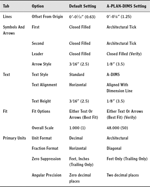
- In the Linear Dimensions group, make the following changes, starting at the top:
- Change the Unit Format setting from Decimal to Architectural.
- Change the Precision setting to
 .
. - Change the Fraction Format setting to Diagonal.
- In the Zero Suppression group, uncheck 0 inches.
- In the Angular Dimensions group, leave Decimal Degrees as the Units Format setting. Change Precision to two decimal places, as you did for the basic drawing units in Chapter 3, “Setting Up a Drawing.” Leave the Zero Suppression section as it is.
After these changes, the Primary Units tab looks like Figure 12.9.
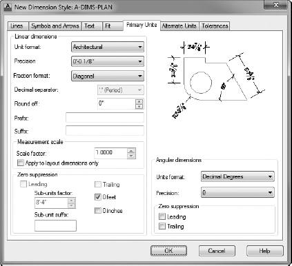
![]() NOTE Zero Suppression controls whether the zero is shown for feet when the dimensioned distance is less than 1 foot and also whether the zero is shown for inches when the distance is a whole number of feet. For the cabin drawing, you'll suppress the zero for feet, but you'll show the zero for inches. As a result, 9″ will appear as 9″, and 3′ will appear as 3′-0″.
NOTE Zero Suppression controls whether the zero is shown for feet when the dimensioned distance is less than 1 foot and also whether the zero is shown for inches when the distance is a whole number of feet. For the cabin drawing, you'll suppress the zero for feet, but you'll show the zero for inches. As a result, 9″ will appear as 9″, and 3′ will appear as 3′-0″.
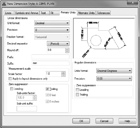
Setting Up the Primary Units Tab (Metric)
If your drawing is set up to use architectural units and you've completed the previous section, skip this section and continue with the next, “Completing the Dimension Style Setup.”
In the preview window, you might have noticed that the numbers in the dimension text maintain a decimal format with four decimal places rather than the feet-and-inches format of the current architectural units. Dimensions have their own units setting, independent of the basic units for the drawing as a whole. On the Primary Units tab, you'll set the dimension units:
- Click the Primary Units tab, and take a peek ahead at Figure 12.10 to see how it's organized. It has two groups: Linear Dimensions and Angular Dimensions, each of which has several types of settings.
FIGURE 12.10 The Primary Units tab after changes have been made using metric units
- In the Linear Dimensions group, starting at the top, make the following changes:
- Make sure Unit Format is set to Decimal.
- Change the Precision setting to 0.
- In the Suffix box, enter mm, making sure you add a space before the first m.
- In the Zero Suppression group, make sure Trailing is checked and Leading is not.
 NOTE Zero Suppression controls whether the zero is shown for measurements when the dimensioned distance is less than 1 millimeter and whether the zero is shown when the final digits, to the right of the decimal point in the dimension, are zeros. For the cabin drawing, you'll suppress the trailing zeros but not the leading zeros. As a result, .9500 will appear as 0.95 with Precision set to 0. This won't be a factor during these exercises.
 - In the Angular Dimensions group, leave Decimal Degrees as the Units Format setting and change Precision to two decimal places, as you did for the basic drawing units in Chapter 3. For now, leave the Zero Suppression group as it is.
After these changes, the Primary Units tab looks like Figure 12.10.
Completing the Dimension Style Setup
Any industry involved in global projects may use the Alternate Units tab, and the mechanical engineering trades and professions use the Tolerances tab. You won't need to make any changes to these last two tabs for this tutorial, but you'll take a brief look at them in the following sections.
First, it's time to save these settings changes to the new A-DIMS-PLAN dimension style and to begin dimensioning the cabin:
- Click the OK button at the bottom of the New Dimension Style dialog box.
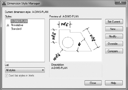
You're returned to the Dimension Style Manager dialog box (see Figure 12.11).
A-DIMS-PLAN appears with a gray background in the Styles list box, along with Standard and Annotative. In the lower-right corner of the dialog box, in the Description group, you'll see the name of the new style. See Table 12.1, later in this section, as a reference for the differences between the Standard style that you started with and the A-DIMS-PLAN style.
- Click A-DIMS-PLAN to highlight it in a dark blue.
FIGURE 12.11 The Dimension Style Manager dialog box with A-DIMS-PLAN listed
- Click the Set Current button and then click the Close button.
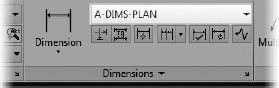
You're returned to your drawing, and the Dimensions panel displays A-DIMS-PLAN in the Dimension Style drop-down list, as shown in Figure 12.12. This indicates that A-DIMS-PLAN is now the current dimension style.
FIGURE 12.12 The Dimensions panel showing A-DIMS-PLAN as the current dimension style
- Save your drawing as I12-01-DimensionStyle.dwg (M12-01-DimensionStyle.dwg).
You have made changes to 16 settings that control dimensions. This isn't too many, considering that there are more than 50 dimension settings. Table 12.1 summarizes the changes you've made so that the dimensions will work with the cabin drawing.
You'll change a few more settings throughout the rest of this chapter as you begin to dimension the cabin in the next set of exercises. Now you'll look briefly at the Alternate Units and Tolerances tabs.
![]() NOTE The next two sections describe dimensioning features that you won't use in the cabin project. If you would rather begin dimensioning the cabin and look at this material later, skip to the “Placing Dimensions on the Drawing” section.
NOTE The next two sections describe dimensioning features that you won't use in the cabin project. If you would rather begin dimensioning the cabin and look at this material later, skip to the “Placing Dimensions on the Drawing” section.
Exploring the Alternate Units Tab
If your work requires your dimensions to display both metric and architectural units, use the Alternate Units tab in the New Dimension Style dialog box or in the Modify Dimension Style dialog box when you are changing an existing style. In the example shown in Figure 12.13, the primary units setting is Architectural (Decimal).
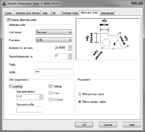
FIGURE 12.13 The Alternate Units tab after being set up for millimeters
TABLE 12.1: Changes made so far
Now you'll set up the alternate units:
- Continue using I12-01-DimensionStyle.dwg (M12-01-DimensionStyle.dwg), or open it if it's not already open.
- Click the Dimension Style button on the Annotate tab Dimensions panel.
- Highlight A-DIMS-PLAN in the Dimension Style Manager, if it's not already highlighted.
- Click the Modify button to open the Modify Dimension Style dialog box.
This is identical to the New Dimension Style dialog box that you used in the previous sections.
- Click the Alternate Units tab.
You'll make only three or four changes on this tab. Look back to Figure 12.13 to see what the style will look like when you're finished here.
- In the upper-left corner of the tab, select the Display Alternate Units check box.
This makes the rest of the settings on the tab available to you for making changes.
- If Decimal (Architectural) isn't displayed in the Unit Format drop-down list, select it.
- If Precision isn't set to
 , open that drop-down list and select that level of precision.
 - If the Unit Format under Alternate Units is Decimal, set Multiplier For Alt Units to 25.4.
This makes millimeters the alternate units. If the alternate units format is Architectural, then set Multiplier For Alt Units to 0.039370. This makes inches the alternate units.
If you want centimeters to be the alternate units, change the Multiplier For Alt Units setting to 2.54 and set Precision to 0.00.
- Enter mm (including a space before the first m) as the Suffix within the Alternate Units group.
Setting this value helps designate the appropriate unit within your dimensions. Prepending your text with a space ensures that there is an appropriate separation between the numerical dimension and the unit designator.
- In the lower-right quarter of the tab, in the Placement group, select Below Primary Value.
This has the effect of placing the alternate units below the primary units and on the opposite side of the dimension line. The tab should look like Figure 12.13.
- Uncheck the Display Alternate Units check box; you don't need to use these settings.
You won't be using alternate units when you dimension the cabin.
Exploring the Tolerances Tab
AutoCAD offers features with options that help you create several kinds of tolerances: allowable variances from the stated dimension. These are very common in the machining and manufacturing industries, where it's understood that the dimensions given are only approximations of the part fabricated. Tolerances are usually measured in thousandths of an inch or hundredths of a millimeter.
The Tolerances tab provides four methods for creating what are called lateral tolerances, the traditional kind of tolerance that most draftspeople use. This is the plus or minus kind of tolerance. Open the Modify Dimension Style dialog box, click the Tolerances tab, and look at the choices in the Method drop-down list, shown in Figure 12.14.
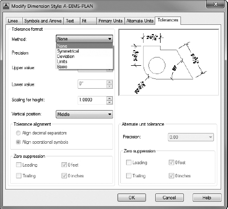
FIGURE 12.14 The Tolerances tab, showing the Method drop-down list options
Each of these is a method for displaying a plus or minus type of tolerance:
None No tolerances are displayed.
Symmetrical This method is for a single plus or minus expression after the base dimension. It's used when the upper-allowable limit of deviation is identical to that for the lower limit, as in 1.0625 ± 0.0025.
Deviation This method is used when the upper-allowable deviation is different from that of the lower deviation. For example, the upper limit of the deviation can be +0.0025, and the lower limit can be −0.0005. The two deviation limits are stacked and follow the base dimension.
Limits In this method, the tolerances are added to or subtracted from the base dimension, resulting in maximum and minimum total values. The maximum is placed over the minimum. In the example for the Symmetrical method, 1.0650 is the maximum and 1.0600 is the minimum.
Basic The base dimension is left by itself, and a box is drawn around it indicating that the tolerances are general, apply to several or all dimensions in boxes, and are noted somewhere else in the drawing. Often, basic dimensions appear when a dimension is theoretical or not exact.
When you select one of these options, one or more of the following settings becomes available. If you select Deviation or Limits, all settings become available:
Precision Controls the overall precision of the tolerances.
Upper Value and Lower Value The actual values of the tolerances.
Scaling For Height The height of the tolerance text. A value of 1 here sets the tolerance text to match that of the base dimension. A value greater than 1 makes the tolerance text greater than the base dimension text, and a value less than 1 makes it smaller than the base dimension text.
Vertical Position Indicates where the base dimension is placed vertically relative to the tolerances. It can be in line with the upper or lower tolerance or in the middle.
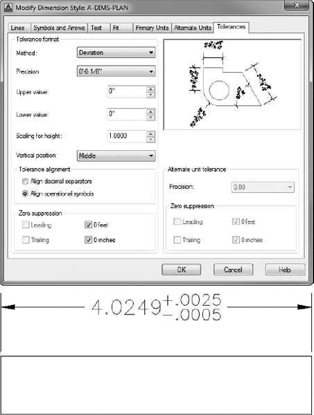
At the bottom, the Zero Suppression options (which are not available when Basic is the tolerance format), when checked, suppress extra zeros that occur before or after the decimal point. If you set up the Tolerances tab as shown at the top of Figure 12.15, a dimension looks like the one shown at the bottom of the figure.
A more complex family of tolerances is available through the Dimensions panel. It's called geometric tolerancing, and it involves setting up a series of boxes that contain symbols and numbers that describe tolerance parameters for form, position, and other geometric features. Usually two to six boxes appear in a row, with the possibility of multiple rows. These all constitute the feature control frame, which eventually is inserted in the drawing and attached in some way to the relevant dimension. Follow these steps:
-
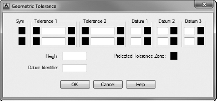
 Click the Tolerance button from the expanded Dimensions panel on the Annotate tab to open the Geometric Tolerance dialog box (see Figure 12.16).
FIGURE 12.15 The Tolerances tab with some settings changed (top) and a resulting dimension with deviation tolerances (bottom)
FIGURE 12.16 The Geometric Tolerance dialog box
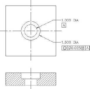
This is where you will set up the feature control frame. The black squares will contain symbols, and the white rectangles are for tolerance or datum values or for reference numbers.
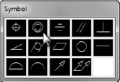
- Click in the top Sym box on the left to open the Symbol dialog box.
This contains 14 standard symbols that describe the characteristic form or position for which the tolerance is being used. When you select one of the symbols, the window closes, and the symbol is inserted into the SYM box.
- Click the icon in the top row that consists of two concentric circles, as shown in Figure 12.17.
FIGURE 12.17 The Symbol dialog box
- Click the top-left black square in the Tolerance 1 group.
This inserts a diameter symbol.
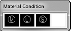
- Click the top-right black square in the Tolerance 1 group.
The Material Condition dialog box (see Figure 12.18) opens, and it displays the three material condition options. When you click one, it's inserted in the top-right square of Tolerance 1. If you need them, you can insert any of these three symbols in Tolerance 2 and Datum 1, 2, or 3.
FIGURE 12.18 The Material Condition dialog box
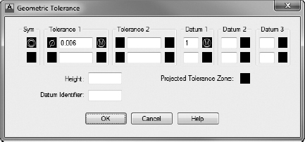
- Fill in the actual tolerance value(s) and datum references in the text boxes, as shown in Figure 12.19.
FIGURE 12.19 The Geometric Tolerance dialog box with a few values provided
- When you're finished, click OK.
You can insert the feature control frame into your drawing like a block and reference it to a part or a dimension, as shown in Figure 12.20.
FIGURE 12.20 Geometric dimensioning on a machined part
- If open, close I12-01-DimensionStyle.dwg (M12-01-DimensionStyle.dwg), discarding any changes to the drawing when prompted.
This exercise was intended to show you the tools that AutoCAD provides for setting up the most commonly used lateral and geometric tolerances when you use the Tolerances tab in the Modify Dimension Style dialog box and the Tolerance button on the Dimensions panel. My intention here isn't to explain the methodology of geometric tolerances or the meanings of the various symbols, numbers, and letters used in them. That is a subject beyond the scope of this book.
Placing Dimensions on the Drawing
Upon returning to your drawing, it should still look almost exactly like Figure 12.1 (shown earlier), and it should have the following:
- A new layer called A-ANNO-DIMS, which is current.
- A new dimension style called A-DIMS-PLAN, which is current and is now displayed in the drop-down list on the Dimensions panel.
- Most of the layers frozen.
- The Endpoint osnap running. (Other osnaps may be running, but only Endpoint is important to this exercise.)
- On the status bar: Ortho mode, Polar Tracking, and Object Snap Tracking off.
- A new text style called A-DIMS, which is current.
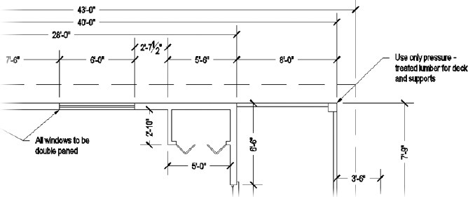
Placing Horizontal Dimensions
First you'll dimension across the top of the plan, from the corner of the building to the closet wall, and then to the other features on that wall. Then you'll dimension the decks and roof.
- Open I12-01-DimensionStyle.dwg(M12-01-DimensionStyle.dwg), and zoom in to the area around the closet.
-
 Click the Linear Dimension button at the left side of the Dimensions panel on the Annotate tab to activate the DIMLINEAR command.
If the Linear Dimension button isn't visible, click the down-arrow below the current dimension command and then choose Linear from the drop-down list. The prompt reads Specify first extension line origin or <select object>:.
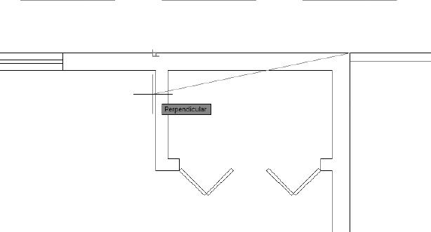
- Pick the upper-right corner of the cabin walls.
The prompt changes to Specify second extension line origin:.
- Activate the Perpendicular osnap, place the cursor over the outside of the closet wall as shown in Figure 12.21, and then click.
FIGURE 12.21 Selecting the wall with the Perpendicular osnap
- At the Specify dimension line location or: prompt, click a point above the roofline to place the dimension in the drawing (see the top of Figure 12.22).
Also notice that the left extension line starts perpendicular to the wall you picked.
- Click anywhere on the new dimension.
The dimension becomes dashed, and five grips appear (see the bottom of Figure 12.22).
NOTE When you need to adjust a dimension, click and drag the necessary grip. You'll learn more about using grips to modify dimensions in the “Modifying Dimensions” section later in this chapter. - Press Esc to deselect the dimension.
- Save this drawing as I12-02-HorizDimension.dwg (M12-02-HorizDimension.dwg).
Your first dimension is completed.
When dimensioning a drawing, you usually dimension to the outside or centerline of the objects and to each significant feature. The next dimension will run from the left side of the first dimension to the right side of the window.
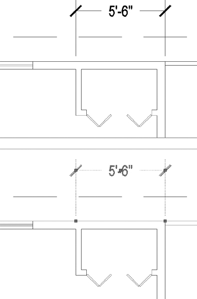
FIGURE 12.22 The dimension attached to the cursor (top) and the grips associated with a dimension (bottom)
![]() NOTE Studs are the vertical 2″ × 4″ (51 mm × 102 mm) or 2″ × 6″ (51 mm × 152 mm) members in the framing of a wall. When dimensioning buildings that have stud walls, architects usually dimension to the face of the stud rather than the outside surface of the wall material, but I won't go into that level of detail in this book.
NOTE Studs are the vertical 2″ × 4″ (51 mm × 102 mm) or 2″ × 6″ (51 mm × 152 mm) members in the framing of a wall. When dimensioning buildings that have stud walls, architects usually dimension to the face of the stud rather than the outside surface of the wall material, but I won't go into that level of detail in this book.
Using the Dimension Continue Command
AutoCAD has an automatic way of placing adjacent dimensions in line with one another—the DIMCONTINUE (Dimension Continue) command. You use it as follows:
- Continue using I12-02-HorizDimension.dwg (M12-02-HorizDimension.dwg), or open it if it's not already open.
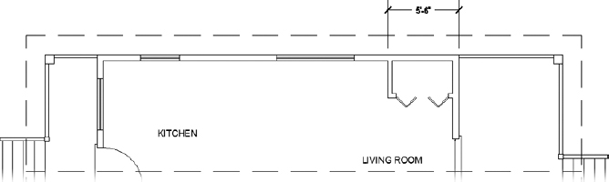
- Zoom out, and pan until you have a view of the upper wall and roofline, with space above them for dimensions (see Figure 12.23).
FIGURE 12.23 The result of zooming and panning for a view of the top of the floor plan
-
 Start the DIMCONTINUE (Dimension Continue) command by selecting the Continue button on the Annotate tab Dimensions panel.
If it's not visible, click the down-arrow next to the Baseline button and choose Continue from the fly-out menu.
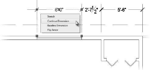
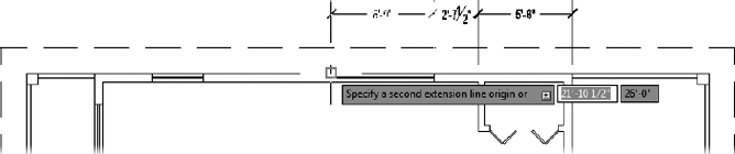
The prompt asks you to Specify a second extension line origin or [Undo/Select] <Select>. All you need to do here is pick a point for the right end of the dimension—in this case, the right corner of the nearest window.
- Click the right corner of the living room window.
This draws the second dimension in line with the first (see Figure 12.24). Note that the same prompt has returned to the command-line interface. You can keep picking points to place the next adjacent dimension in line.
FIGURE 12.24 Using the DIMCONTINUE command
- Continue adding dimensions with the DIMCONTINUE command by clicking (moving right to left) the endpoints of the window openings, the endpoint of the wall, and the end of the deck.
CONTINUE DIMENSIONS WITH MULTIFUNCTION GRIPS
In addition to the Ribbon, dimensions may also be continued by utilizing multifunction grips. To access the DIMCONTINUE command using multifunction grips, follow these steps:
- Select the dimension you would like to continue.
- Hover over but do not select the dimension-line grip on the side to continue. The grip turns red, and the contextual multifunction grip menu displays.
- Choose Continue Dimension from the contextual multifunction grip menu to launch the DIMCONTINUE command.
- Use the Linear tool to add a dimension for the width of the front deck and the Perpendicular osnap to align the dimension lines.
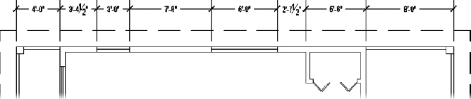
When you're finished, your dimensions should look like Figure 12.25.
FIGURE 12.25 Dimensions added to each critical point along the top wall
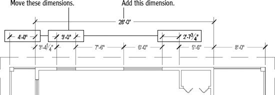
Some of the dimensions, particularly those on the left end of the cabin, appear cluttered with some of the arrowheads and text overlapping.
- Select the dimensions that need adjustment, and use the grips near the arrows or at the text to adjust the dimension line or text location (see Figure 12.26).
FIGURE 12.26 Adjusted dimensions with an overall cabin dimension added
- Finally, add a linear dimension from the end of the front deck to the beginning of the cabin, and another overall dimension from one end of the cabin to another, as shown in Figure 12.26.
- Save this drawing as I12-03-DimContinue.dwg (M12-03-DimContinue.dwg).
With the DIMCONTINUE (Dimension Continue) command, you can dimension along a wall of a building quickly just by picking points. AutoCAD assumes that the last extension line specified for the previous dimension will coincide with the first extension line of the next dimension. If the extension line from which you need to continue isn't the last one specified, press ![]() at the prompt, pick the extension line from which you want to continue, and resume the command.
at the prompt, pick the extension line from which you want to continue, and resume the command.
Another automation strategy that you can use with linear dimensions is the Dimension Baseline tool.
Using the Dimension Baseline Command
The DIMBASELINE (Dimension Baseline) command gets its name from a style of dimensioning called baseline, in which all dimensions begin at the same point (see Figure 12.27). Each dimension is stacked above the previous one. Because of the automatic stacking, you can use the Dimension Baseline tool for overall dimensions. AutoCAD will stack the overall dimension a set height above the incremental dimensions.
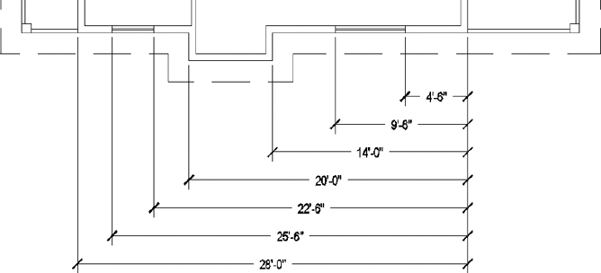
FIGURE 12.27 An example of baseline dimensions
The steps for creating baseline dimensions are listed here:
- Create a linear dimension.
-
 Click the down-arrow next to the Continue button in the Annotate tab Dimensions panel, and then click the Baseline option.
The prompt reads Specify a second extension line origin or [Undo/Select] <Select>:, just like the first prompt for the DIMCONTINUE (Dimension Continue) command.
- Pick the next feature to be dimensioned.
- Repeat step 3 as necessary to add the required dimensions.
- Press Esc to end the DIMBASELINE command.
![]() TIP Try accessing the DIMBASELINE (Dimension Baseline) command by using multifunction grips. To access the contextual multifunction grip menu, hover over the dimension-line grip, holding your cursor in place until the contextual menu displays.
TIP Try accessing the DIMBASELINE (Dimension Baseline) command by using multifunction grips. To access the contextual multifunction grip menu, hover over the dimension-line grip, holding your cursor in place until the contextual menu displays.
Setting Up Vertical Dimensions
Because you can use the Linear Dimension tool for vertical and horizontal dimensions, you can follow the steps in the previous exercise to do the vertical dimensions on the right side of the floor plan. The only difference from the horizontal dimensioning is that you need two sets of dimensions: one for the wall and another for the deck. The following steps will take you through the process of placing the first vertical dimension. You'll then be able to finish the rest of them by yourself.
- Continue using I12-03-DimContinue.dwg (M12-03-DimContinue.dwg), or open it if it's not already open.
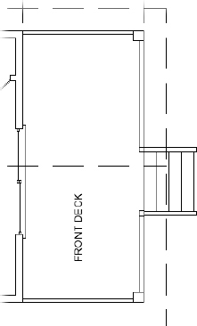
- Pan and zoom to get a good view of the right side of the floor plan, including the front deck (see Figure 12.28).
FIGURE 12.28 The result of zooming and panning for a view of the right side of the floor plan
- Click the Linear button, and then start a vertical dimension from the top of the right exterior wall.
- Place the second point at the endpoint on the opening of the sliding door.
- Click to place the dimension between the wall and the FRONT DECK text.
- Adjust the location of the text if needed (see the top image of Figure 12.29).
FIGURE 12.29 The dimension drawn to the start of the sliding door opening (top), and the completed first set of vertical dimensions (bottom)
- Use the Dimension Continue tool and grips to draw and edit the remaining two dimensions for the front of the cabin (see the bottom image of Figure 12.29).
- Using a similar procedure, draw the vertical dimensions for the front deck, placing the dimensions to the right of the deck.
- Add a horizontal dimension showing the length of the stairway.
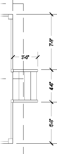
When you're finished, your dimensions should look like those shown in Figure 12.30.
- Save this drawing as I12-04-VerticalDimensions.dwg (M12-04-VerticalDimensions.dwg).
FIGURE 12.30 The dimensions for the front deck

Finishing the Dimensions
You place the rest of the horizontal and vertical dimensions using a procedure similar to the one you used to complete the horizontal dimensions. Here is a summary of the steps:
- Continue using I12-04-VerticalDimensions.dwg (M12-04-VerticalDimensions.dwg), or open it if it's not already open.
- Use the Linear Dimension and Dimension Continue tools to add horizontal dimensions to the bottom side of the building. Move the title and label text as required to display the dimensions clearly.
- Add dimensions to the rear of the cabin and for the rear deck.
- Dimension the roof.
- Dimension the inside of the bathroom:
- Start the Linear Dimension (DIMLINEAR) tool.
- Press to allow the selection of an object, rather than a starting point for a dimension.
- Click one of the vertical walls, and then click to place the dimension.
The completed dimensions will be similar to Figure 12.31.
- Save your drawing as I12-05-FinishedDimensions.dwg (M12-05-FinishedDimensions.dwg).
Using Other Types of Dimensions
AutoCAD provides tools for placing radial and angular dimensions on the drawing and for placing linear dimensions that are neither vertical nor horizontal. You'll make some temporary changes to the cabin file that you just saved so that you can explore these tools, and then you'll close the drawing without saving it:
- Make layer 0 current.
- Freeze the A-ANNO-TEXT, A-ANNO-DIMS, A-ELEV-DECK, and A-ELEV-DECK-STRS layers.
- Use the FILLET command to fillet the top-right corner of the roof with a radius of 5′-0″ (1525 mm).
FIGURE 12.31 The completed dimensions
- Start the LINE command, and then pick the lower-right corner of the roof as the start point.
- Activate the Nearest osnap, and pick a point on the roof's ridgeline.
The right end of the cabin should look like Figure 12.32.
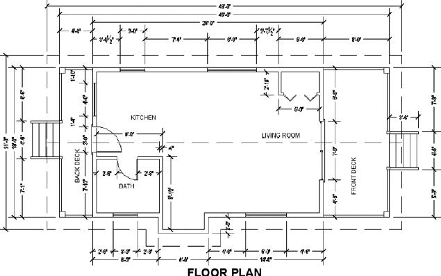
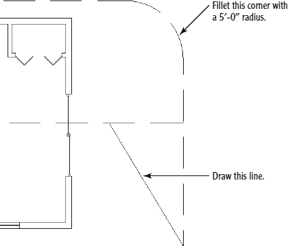
FIGURE 12.32 The right end of the cabin after some temporary changes are implemented
Using Radial Dimensions
On the drop-down menu on the left side of the Dimensions panel are icons for the Radius, Diameter, and Arc Length dimensions. They all operate the same way and are controlled by the same settings.
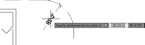
Follow these steps to place a radius dimension at the filleted corner, measuring the distance from the curve to the center point:
- Click the Osnap button on the status bar to disable any running osnaps temporarily.
-
 Click the arrow below the Linear button on the Annotate tab Dimensions panel, and then click the Radius button to start the DIMRADIUS command.
 - Click the inside filleted corner well above the midpoint.
The radius dimension appears, and the text is attached to the cursor. Where you pick on the curve determines the angle of the radius dimension (see Figure 12.33).
FIGURE 12.33 The radius dimension initially positioned on the curve
- Click to place the radius text in the dimension.
The R prefix indicates that this is a radial dimension.
![]() NOTE Most of the commands used for dimensioning are prefaced with DIM when you enter them at the command line—that is, DIM is part of the command name. For example, when you click the Radius button on the Annotate tab
NOTE Most of the commands used for dimensioning are prefaced with DIM when you enter them at the command line—that is, DIM is part of the command name. For example, when you click the Radius button on the Annotate tab ![]() Dimensions panel or Dimension toolbar, you see _DIMRADIUS in the command line to let you know that you have started the DIMRADIUS command. You can also start this command by entering DIMRADIUS
Dimensions panel or Dimension toolbar, you see _DIMRADIUS in the command line to let you know that you have started the DIMRADIUS command. You can also start this command by entering DIMRADIUS![]() or DRA
or DRA![]() (the command alias).
(the command alias).
The radial dimension you just inserted uses the same architectural tick, which is used by the other linear dimensions in your drawing. Typically, an arrow, not an architectural tick, would be used to illustrate radial dimensions. To fix this, you will need to create a Child Dimension style. You'll learn how to create parent and child dimension styles at the end of this section, under “Setting Up Parent and Child Dimensioning Styles.”
Adding a Diameter Dimension
Similar to the radius dimension, a diameter dimension measures the distance from one side of a circle or arc, through the center point, to the other end. Follow these steps to place a diameter at the filleted corner:
- Erase the radius dimension.

Click the arrow below the Radius button on the Dimension panel within the Annotate tab, and then click the Diameter button to start the DIMDIAMETER command.
- Click the inside filleted corner near the location where it meets the vertical wall.
The diameter dimension appears, and the text is attached to the cursor.
- Click to place the radius text in the dimension. The Ø prefix indicates that this is a diameter dimension. Where you pick on the curve determines the angle of the radius dimension (see Figure 12.34).
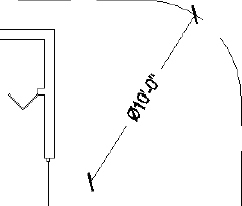
FIGURE 12.34 The diameter dimension positioned on the curve
Like the radial dimension you created a moment ago, the diameter dimension also uses architectural ticks as opposed to the more standard arrows. Completing the process outlined in “Setting Up Parent and Child Dimensioning Styles” will walk you through how to make this fix.
Adding an Arc Length
An arc length dimension measures the length of an arc or polyline arc segment. As shown in Figure 12.35, an arc symbol, or cap, precedes the text to identify it as an arc length dimension.
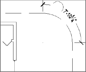
FIGURE 12.35 The arc length dimension positioned on the curve
![]() TIP You can change the location of the arc length symbol, from in front of the text to over it, or eliminate it altogether in the Symbols And Arrows tab of the Modify Dimension Style dialog box.
TIP You can change the location of the arc length symbol, from in front of the text to over it, or eliminate it altogether in the Symbols And Arrows tab of the Modify Dimension Style dialog box.
Follow these steps to place an arc length dimension at the filleted corner:
- Erase the diameter dimension.
-
 Click the arrow below the Diameter button on the Dimension panel within the Annotate tab, and then click the Arc Length button to start the DIMARC command.
 - Click anywhere on the arc at the filleted corner, and the arc length dimension appears attached to the cursor.
- Click to locate the dimension (see Figure 12.35).
Setting Up Parent and Child Dimensioning Styles
The A-DIMS-PLAN dimension style that you set up at the beginning of this chapter applies to all dimensions, and it is called the parent dimension style. You can change settings in this dimension style for particular types of dimensions, such as the radial type. This makes a child dimension style.
The child version is based on the parent version, but it has a few settings that are different. In this way, all your dimensions will be made by using the A-DIMS-PLAN dimension style, but radial dimensions will use a child version of the style. Once you create a child dimension style from the parent style, you refer to both styles by the same name, and you call them a dimension style family. Follow these steps to set up a child dimension style for radial dimensions:
- Click the Dimension Style button at the right end of the Dimensions panel to open the Dimension Style Manager dialog box.
- With the parent style A-DIMS-PLAN highlighted in the Styles list, click the New button to open the Create New Dimension Style dialog box.
- Open the Use For drop-down list, select Radius Dimensions, and then click the Continue button.
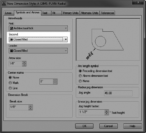
The New Dimension Style: A-DIMS-PLAN: Radial dialog box opens and has the seven tabs that you worked with earlier. Had you selected a different option in the Use For drop-down list, it would replace Radial in the title of the dialog box.
By default, the values in the Child Dimension Style dialog box will be the same as the values found in its parent. For instance, switching to the Symbols And Arrows tab will reveal that the Arrowhead setting is Architectural Tick, the same as the parent A-DIMS-PLAN style.
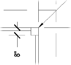
- From the Symbols And Arrows tab, click the Second drop-down list within the Arrowheads group to change from Architectural Tick to Closed Filled, as shown in Figure 12.36.
The change you just made will not affect the way you actually create dimensions. You'll still use the A-DIMS-PLAN dimension style. The only difference is that when you create a radius dimension, it will use a filled arrow instead of the architectural tick that was used when creating a radius dimension earlier.
- Click OK to close the New Dimension Style dialog box.
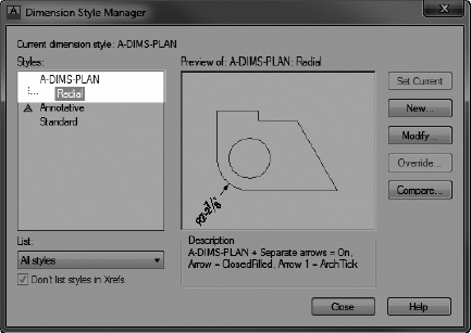
In the Dimension Style Manager dialog box, notice in the Styles list, as shown in Figure 12.37, that the current dimension style now has a child style for Radial dimensions indented below it.
FIGURE 12.36 Changing the Arrowhead style for the Radial A-DIMS-PLAN child style
FIGURE 12.37 The Radial child style shown as a node in the Dimension Style Manager
- Click Close to close the Dimension Style Manager dialog box.
- Using the Radius tool found on the Dimensions panel within the Annotate tab, redraw the same radial dimension you created earlier.
The result should look like Figure 12.38.
FIGURE 12.38 The Radius dimension after creating a child style
Notice that the arrowhead is no longer an architectural tick, but rather a closed arrow. Despite this override to radial dimensions, linear dimensions will still use the architectural tick.
Using Aligned and Angular Dimensions
To become familiar with the aligned and angular dimension types, you'll experiment with the line you drew from the opposite corner of the roof in the previous exercise.
Using Aligned Dimensions
Aligned dimensions are linear dimensions that aren't horizontal or vertical. You place them in the same way that you place horizontal or vertical dimensions with the Dimension Linear tool. You can also use the Dimension Baseline and Dimension Continue tools with aligned dimensions.
Use the Aligned Dimension tool, which works just like the Linear Dimension tool, to dimension the line you drew at the beginning of this exercise. Follow these steps to add an aligned dimension:
- Zoom in to the lower-right corner of the cabin roof.
- Click the down-arrow on the right side of the Annotate tab Dimensions panel, and then click the Aligned button.

- Press to switch to accept the Select Object option.
The cursor changes to a pickbox.
- Pick the diagonal line.
The dimension appears attached to the cursor.
- Click to place the dimension.
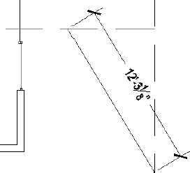
Your drawing should look similar to Figure 12.39.
FIGURE 12.39 An aligned dimension added to the cabin drawing
Using Angular Dimensions
The angular dimension is the only basic dimension type that uses angles in the dimension text instead of linear measurements. Try making an angular dimension on your own. Because the default arrowhead style for the A-DIMS-PLAN dimension style is Architectural Ticks, you'll want to create another child style for angular dimensions. Refer to the “Setting Up Parent and Child Dimensioning Styles” exercise earlier in this chapter for step-by-step instructions on how to do this. To summarize, you'll need to do the following to create an angular child style:
- Open the Dimension Style Manager, select the A-DIMS-PLAN dimension style, and click New.
- Change the Use For drop-down list to Angular, and click Continue.
- From the Symbols And Arrows tab, change the First and Second Arrowhead styles to Closed Filled and then click OK.
- Close out of the Dimension Style Manager to return to your drawing.
With the Angular child style in place, you're ready to add an angular dimension to your drawing. Follow these steps to add an angular dimension to your drawing:
- Turn off Object Snap mode.
- Start the DIMANGULAR command by selecting the Angular tool on the Annotate tab Dimensions panel.

- Follow the prompts; pick the line you drew, and then pick the horizontal roofline.
- Click a point inside your drawing to insert the angular dimension.
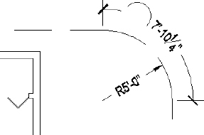
When you're finished, your drawing will look like Figure 12.40.
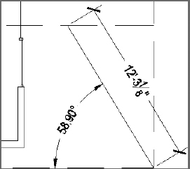
FIGURE 12.40 The roof with the angular dimension added
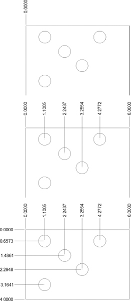
Using Ordinate Dimensions
Ordinate dimensions are widely used by the mechanical engineering profession and related trades. They differ from the kind of dimensioning you have been doing so far in this chapter in that ordinate dimensioning specifies x- and y-coordinate values for specific points in a drawing based on an absolute or relative Cartesian Coordinate System, rather than on a distance between two points. This method is used to dimension centers of holes in sheet metal or machine parts.
You don't need ordinate dimensions in the cabin project, so you'll now go through a quick exercise in setting them up to dimension the holes in a steel plate. Doing so will give you a glimpse of the tools that AutoCAD provides for this type of work. (If you aren't interested in ordinate dimensioning, move on to the next section, “Using Leader Lines,” to modify the dimensions you've already created for the cabin.)
- Open a new drawing, and leave the units at the default of Decimal with a precision of four decimal places.
- Turn on Polar Tracking.
- Set up a new text style, and set 0.125 as the height.
- Click Apply and then Close to make it the current text style.
- Draw a rectangle using 0,0 as the first point and 6,−4 as the second.
- Use Zoom To Extents, and then zoom out to see the area around the object.
- Use the UCSICON command to move the icon to the Noorigin position.
- Somewhere in the upper-left quadrant of the rectangle, draw a circle with a radius of 0.35 units.
- Using Polar Tracking or Ortho mode, copy that circle once directly to the right, once directly below the original, and to two other locations that are not aligned with any other circle, so that the configuration looks something like the top of Figure 12.41.
- Set the Endpoint and Center osnaps to be running, and turn on Ortho mode.
What you are concerned with in ordinate dimensioning isn't how far the holes are from each other, but how far the x- and y-coordinates of the centers of the holes are from a reference point on the plate. You'll use the upper-left corner of the plate as a reference point, or datum point, because it's positioned at the origin of the drawing, or at the 0,0 point.
-
 Click the Ordinate button on the drop-down menu on the Dimensions panel.
 - Click the upper-left corner of the rectangular plate, and then move the cursor straight up above the point you picked.
- When you're about an inch above the plate, click again.
This sets the first ordinate dimension (see the top of Figure 12.41).
- Press the spacebar to repeat the DIMORDINATE command.
FIGURE 12.41 Placing the first ordinate dimension (top), finishing up the x-coordinate dimensions (middle), and placing the y-coordinate dimensions (bottom)
- Repeat steps 12 and 13 for the four circles near the middle or upper portions of the plate, using their centers as points to snap to and aligning the ordinate dimensions by eye.
The lower circle is in vertical alignment with the one above it, so it needs no horizontal dimension.
- Place an ordinate dimension on the upper-right corner of the plate to finish.
Press the F8 key to toggle Ortho mode off if you need to jog an extension line.
The result should look like the middle image of Figure 12.41.
- Repeat this procedure for the y-ordinate dimensions.
Once again, ignore any circles that are in vertical alignment, but include the upper-left and lower-left corners of the plate (see the bottom of Figure 12.41).
The civil engineering discipline typically uses a different type of ordinate dimensions. A datum reference point is used, but the dimensions are displayed at each point in a format typically referred to as northing and easting. Using this format, the y-coordinate is displayed first as the northing location and, separated by a comma, the x-coordinate is displayed as the easting location, as shown in Figure 12.42. Because of this special format, most civil engineers choose a product such as Autodesk® AutoCAD® Civil 3D® that has specialized tools for generating ordinate dimensions in this format.
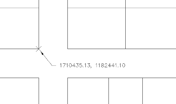
FIGURE 12.42 A sample ordinate-point dimension in a civil engineering plan
When you change settings for a dimension style, dimensions created when that style was current will automatically update to reflect the changes. You'll modify more dimensions in the next section.
You have been introduced to the basic types of dimensions (linear, radial, leader, and angular) and some auxiliary dimensions (baseline, continue, and aligned) that are special cases of the linear type. You can also use the baseline and continuous dimensions with angular dimensions.
Feel free to save the drawing file you created while working through the last several exercises to refer to later. For the purposes of this book, you will not use this specific file again, so you can close your drawing without saving the changes.
Using Leader Lines
You will use the MLEADER (Multileader) command to draw an arrow to features in the cabin drawing in order to add descriptive information. Multileaders are not part of the dimension family, and you can find them on the Multileaders panel.
Creating a Multileader Style
Before you create a leader, you need to create a multileader style, as follows:
- If it's still open, close the drawing you created during the Ordinate Dimensions exercise, and open the I12-05-FinishedDimensions.dwg (M12-05-FinishedDimensions.dwg).
-
Click the Multileader Style Manager button at the lower right of the Leaders panel's title bar on the Annotate tab.
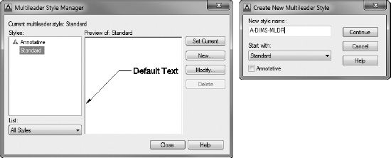
- Click the New button in the Multileader Style Manager.
- In the Create New Multileader Style dialog box that opens, enter A-DIMS-MLDR in the New Style Name text box and then click Continue (see Figure 12.43).
FIGURE 12.43 Creating a new multileader style
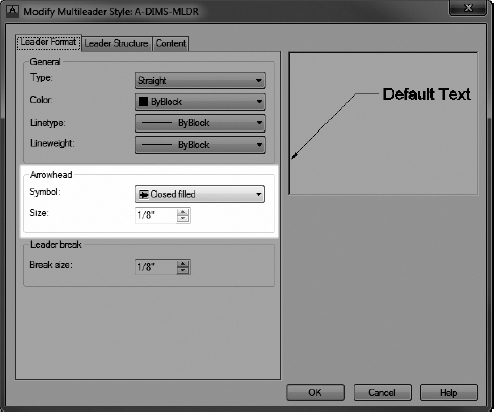
The Modify Multileader Style dialog box opens (see Figure 12.44). This is where you define the leader properties.
FIGURE 12.44 The Modify Multileader Style dialog box
- On the Leader Format tab, verify that the Arrowhead style is set to Closed Filled, and set the Size to (3.5).
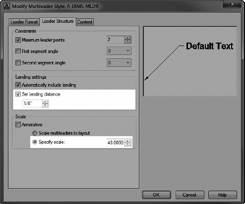
- Click the Leader Structure tab.
The landing is the horizontal line at the end of the leader, just before the text.
- Make sure the Set Landing Distance option is checked, and then enter (3.5) in the text box (see Figure 12.45).
- In the Scale group, make sure the Specify Scale radio button is selected and then click in the text box and enter 48 (50), as shown in Figure 12.45.
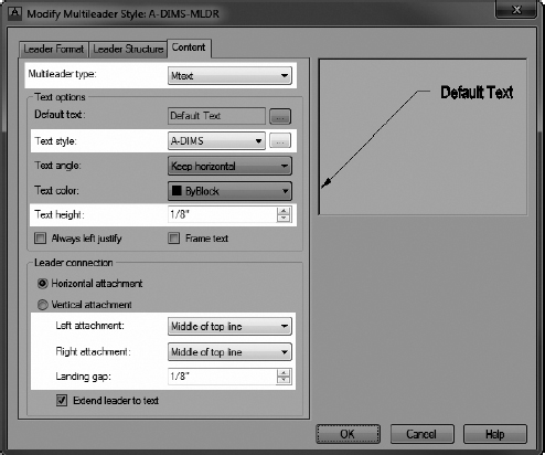
- Switch to the Content tab shown in Figure 12.46.
- Expand the Text Style drop-down list, choose A-DIMS, and set the text height to (3.5).
- In the Leader Connection group, set both the Left Attachment and Right Attachment options to Middle Of Top Line, as shown in Figure 12.46.
This places the middle of the top line of the leader text even with the landing.
FIGURE 12.45 The Leader Structure tab within the Modify Multileader Style dialog box
FIGURE 12.46 The Content tab within the Modify Multileader Style dialog box
- Set the Landing Gap value to (3.5), as shown in Figure 12.46.
- Click the OK button.
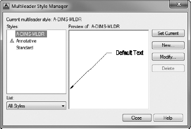
In the Multileader Style Manager, the A-DIMS-MLDR Leader style appears in the Styles list box (see Figure 12.47).
FIGURE 12.47 The A-DIMS-MLDR multileader style shown in the Multileader Style Manager
- Select A-DIMS-MLDR, click Set Current, and then click the Close button.
- Save this drawing as I12-06-MLeaderStyle.dwg (M12-06-MLeaderStyle.dwg).
Adding the Leaders
To add the leaders to the drawing, follow these steps:
- Continue using I12-06-MLeaderStyle.dwg (M12-06-MLeaderStyle.dwg), or open it if it's not already open.
-
 Zoom in to the front deck.
 - Click the Multileader button on the Annotate tab Leaders panel.
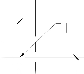
- Activate the Endpoint osnap, if necessary, and then click the top-right corner of the top-right deck post.
- At the Specify leader landing location: prompt, click a point above and to the right of the deck.
The Text Editor tab and panels replace the Annotate tab and panels in the Ribbon, and a flashing vertical cursor appears to the right of the landing, as shown in Figure 12.48.
FIGURE 12.48 The flashing vertical cursor indicates that AutoCAD is waiting for text input.
- Enter Use only pressure-treated lumber for deck and supports.
Longer notes like this one are typically displayed on several lines.
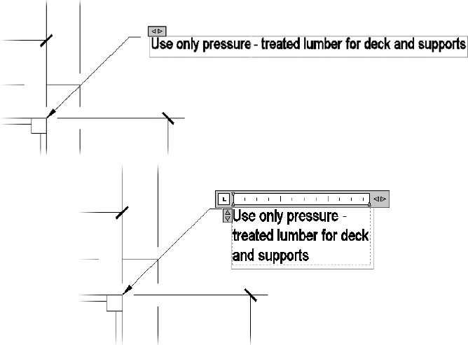
- On the contextual Text Editor Ribbon tab Options panel, click the Ruler tool.
This displays a ruler with two outward-facing arrows above the multileader text (see the top side of Figure 12.49).
- Expand the arrows above the multileader text to the right to expand the text box, and distribute the text among several lines (see the bottom side of Figure 12.49).
- Click a blank spot in the drawing area to complete the text, and return to the Annotate tab.
TIP To reposition a leader without moving the arrow, click it and then click the grip at the middle of the landing. Then move the cursor. When you do, the text, landing, and one end of the leader line will all move with the cursor.
- Pan to the right so that you can see the two windows on the north side of the cabin.
FIGURE 12.49 Multileader text with ruler toolbar (top) and expanded text box distributing text to several lines (bottom)
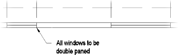
- Add a leader that starts at the right edge of the 3″ (915 mm) window and then extends below and to the right.
- Enter All windows to be double paned at the text prompt.
Adjust the width of the text, and then click a blank spot in the drawing area (see Figure 12.50).
Several leader lines can extend from a single landing.
FIGURE 12.50 The multileader pointing to the first window
-
 Click the Add Leader button on the Leaders panel within the Annotate tab, and then, at the Select a multileader: prompt, click the last leader you made.
An arrowhead with a leader appears attached to the cursor and anchored to the landing.
- Click the left corner of the window to the right and then press .
NOTE AutoCAD may place the second leader on the right side of the text if it determines that the leader fits better there. If this happens, click the multileader to select it and then move the text to the right. The second leader will reposition itself to the left side of the text.
- Reposition the text as necessary.
Your drawing should look similar to Figure 12.51.
FIGURE 12.51 The cabin drawing with leaders
- Save this drawing as I12-07-AddingLeaders.dwg (M12-07-AddingLeaders.dwg).
The final part of this chapter is devoted to teaching you a few techniques for modifying dimensions.
Modifying Dimensions
You can use several commands and grips to modify dimensions, depending on the desired change. Specifically, you can do the following:
- Change the dimension text content
- Move the dimension text relative to the dimension line
- Move the dimension or extension lines
- Change the dimension style settings for a dimension or a group of dimensions
- Revise a dimension style
The best way to understand how to modify dimensions is to try a few. You'll look at how to change the content first.
Editing Dimension Text Content
You can modify any aspect of the dimension text. To change the content of text for one dimension or to add text before or after the dimension, you can use the Properties or Quick Properties palette. You'll change the text in the horizontal dimensions for the cabin and walls by using Quick Properties:
- Continue using I12-07-AddingLeaders.dwg (M12-07-AddingLeaders.dwg), or open it if it's not already open.
- Zoom and pan until your view of the floor plan is similar to Figure 12.52.
FIGURE 12.52 A modified view of the floor plan
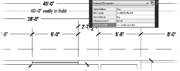
 Select the horizontal 40′-0″ (8550 mm) cabin dimension near the top of the drawing, and then click the Quick Properties button in the status bar. TIP The procedure shown here can also be done in the Text rollout of Properties palette.
- Highlight the Text Override field, and enter <> verify in field.
The phrase is appended to the dimension (see Figure 12.53). The <> instructs AutoCAD to add the phrase to the dimension text; if you had not prefixed the override with <>, the phrase would have replaced the dimension text entirely.
FIGURE 12.53 Adding a phrase to dimension text
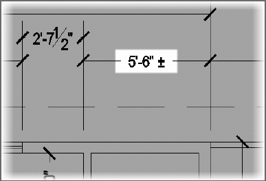
- Press the Esc key, and then click the 5′-6″ (1670 mm) dimension, measuring the distance from the end of the cabin to the closet wall.
- In the Text Override box, enter <> %%P.
The ± symbol is now appended to the text (see Figure 12.54).
FIGURE 12.54 Adding a special character to dimension text
- Save this drawing as I12-08-ModifyDimText.dwg (M12-08-ModifyDimText.dwg).
Unless you have memorized all the ASCII symbol codes, it might be easier to insert symbols into dimension text by using the text-editing tools. To do this, enter TEDIT![]() and then select the dimension text. The default AutoCAD workspace does not provide access to the DDEDIT command through the Ribbon.
and then select the dimension text. The default AutoCAD workspace does not provide access to the DDEDIT command through the Ribbon.
The text is highlighted, and the Text Editor tab is activated. Place the cursor where you want the symbol to appear, and then click the Symbol button in the Insert panel to see a list of available symbols and their related ASCII codes. Click the symbol name to be added (see Figure 12.55).
Next you'll learn about moving a dimension.
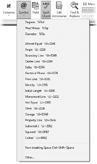
FIGURE 12.55 Inserting symbols from the Text Editor tab
Moving Dimensions
You can use grips to move dimensions. You used grips to move the dimension lines when you were putting in the vertical and horizontal dimensions. This time, you'll move the dimension line and the text:
- Continue using I12-08-ModifyDimText.dwg (M12-08-ModifyDimText.dwg), or open it if it's not already open.
- Zoom in to a view of the upper-left side of the floor plan until you have a view similar to Figure 12.56, which includes the left window and the top of the rear deck and their dimensions.
FIGURE 12.56 The result of zooming in to the upper-left side of the floor plan
- Select the 3′-0″ (915 mm) window dimension. Its grips appear.
- Click the grip on the right arrowhead to activate it.
- Move the cursor down until the dimension text is just below the roofline.
- Click again to fix it there.
- Click the grip that's on the text and, with Polar Tracking on, move the text to the right, outside of the extension line; then click to place it.
- Press Esc to deselect the dimension (see Figure 12.57).
FIGURE 12.57 Moving the window dimension and dimension text with grips
- Select either of the leader lines pointing to the two windows.
The leaders, landing, and leader text ghost, and the grips appear.
- Click the grip at the tip of the left leader and then move the grip to the end of the inner pane of the left window (see Figure 12.58).
- Click the grip at the tip of the right leader, and move the grip to the left end of the inner pane of the right window (also shown in Figure 12.58).
- Save this drawing as I12-09-MovingDims.dwg (M12-09-MovingDims.dwg).
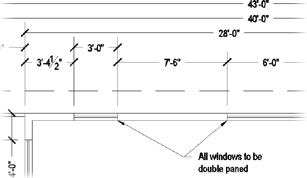

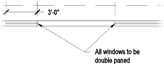
FIGURE 12.58 Using grips to move the position of leader lines
Adjusting Space between Stacked Dimensions
Dimensions for the back deck are stacked in three rows. Because each row of dimensions was placed visually, the spacing between each row is an arbitrary distance. The Adjust Space tool can help fix spacing variations like this one, helping you to produce a more polished and professional-looking drawing. To use the Adjust Space tool, follow these steps:
- Continue using I12-09-MovingDims.dwg (M12-09-MovingDims.dwg), or open it if it's not already open.
- Zoom in to the area around the back deck so that the deck, stairs, and dimensions are each visible.
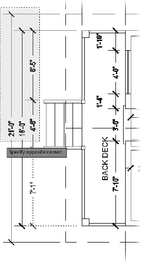
-
 Start the DIMSPACE command by selecting the Adjust Space tool found on the Dimensions panel on the Annotate tab.
 - From the Select base dimension: prompt, pick the 7′-1″ (2160 mm) dimension.
The command line prompts you to select the dimensions on which to adjust spacing.
- Select the remaining dimensions for the back deck, as shown in Figure 12.59, and press .
After selecting the dimensions on which to adjust spacing, you are given an option about how you would like them spaced. You can enter a custom value of your choice or let AutoCAD determine the best spacing for you.
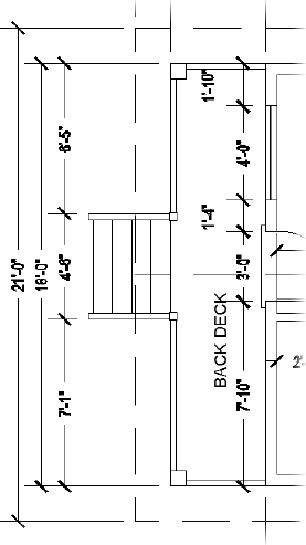
-
Press
to accept the default Auto option.The command ends, and all three rows of dimensions are equally spaced, as shown in Figure 12.60.
- Save this drawing as I12-10-SpacingDims.dwg (M12-10-SpacingDims.dwg).
Using Dimension Overrides
You can suppress the left extension line with the Properties palette, which allows you to change a setting in the dimension style for one dimension without altering the style settings. Follow these steps:
- Continue using I12-10-SpacingDims.dwg (M12-10-SpacingDims.dwg), or open it if it's not already open.
FIGURE 12.59 Selecting the remaining deck dimensions to adjust the spacing
-
Thaw the A-WALL-HEAD layer.
Notice how the white (or black) left extension line for the 8′-0″ (2350 mm) dimension, which measures the width of the bathroom, coincides with the header line for the back door. You could use the Draw Order tools to move the dimension behind the header, but that may still result in a visibly overlapping condition when the drawing is printed. In this case, you'll suppress the extension line, rendering it invisible.
- Double-click the 8′-0″ (2350 mm) dimension to open the Properties palette.
- Scroll down to the Lines & Arrows rollout. If this section isn't open, click the arrow to the right.
- Scroll down the list of settings in this section, and click Ext Line 1.
FIGURE 12.60 All three rows of deck dimensions are equally spaced.
- Click the down-arrow to the right to open the drop-down list. Click Off.
This suppresses the left extension line of the dimension (see Figure 12.61).
- Close the Properties palette.
- Press Esc to deselect the dimension.
- Save this drawing as I12-11-DimOverrides.dwg (M12-11-DimOverrides.dwg).
To illustrate how dimension overrides work, you suppressed an extension line without having to alter the dimension style. Extension lines are usually the thin-nest lines in a drawing. It's usually not critical that they be suppressed if they coincide with other lines, because the other lines will overwrite them in a print.
However, in this example, the left extension line of the 8′-0″ (2350 mm) dimension for the bathroom coincides with the line representing the header of the back door. If the Headers layer is turned off or frozen, you will have to unsuppress the extension line of this dimension so that it will be visible spanning the door opening. Also, if you dimension to a noncontinuous line, such as a hidden line, use the dimension style override features to assign special linetypes to extension lines.
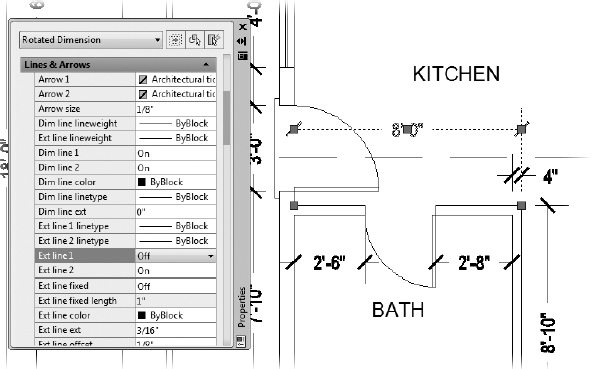
FIGURE 12.61 The 8′-0″ (2350 mm) dimension with the left extension line suppressed
![]() NOTE In the practice exercises at the end of this chapter, you'll get a chance to learn how to incorporate centerlines into your dimensions.
NOTE In the practice exercises at the end of this chapter, you'll get a chance to learn how to incorporate centerlines into your dimensions.
Dimensioning Short Distances
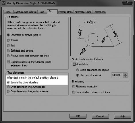
When you have to dimension distances so short that the text and the arrows can't fit between the extension lines, a dimension style setting determines where they are placed. To see how this works, you'll add dimensions to the deck for the widths of the handrails and posts as well as the thickness of an interior wall. Then make a change in the Fit tab to alter the A-DIMS-PLAN dimension style to change where it places text that doesn't fit between the extension lines:
- Continue using I12-11-DimOverrides.dwg (M12-11-DimOverrides.dwg), or open it if it's not already open.
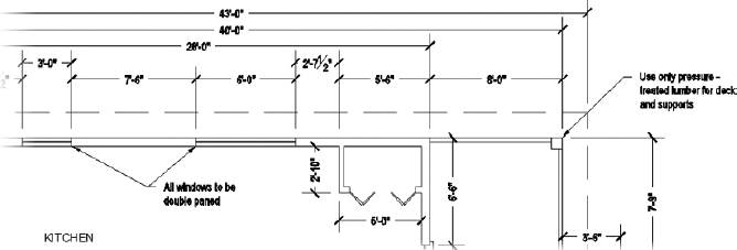
- Zoom and pan to a view of the upper portion of the front deck so that the horizontal dimensions above the floor plan are visible (see Figure 12.62).
FIGURE 12.62 The new view of the upper-right floor plan and its dimensions
- Activate the running osnaps if necessary, click the Linear Dimension button, and pick the upper-left corner of the deck post.
- Pick the lower-left corner of the same deck post.
- Place the dimension line about 2′ (610 mm) to the left of the deck post.
The 8″ (204 mm) dimension is placed even farther to the left of the point you selected (see Figure 12.63).
Open the Dimension Style Manager dialog box, click the Modify button, and then, in the Modify Dimension Style dialog box, click the Fit tab.
Several of the dimensioning commands are also available on the Annotation panel under the Home tab.
FIGURE 12.63 The text for the short dimension is not placed near the dimension lines.
- In the Text Placement group, select the Beside The Dimension Line radio button (see Figure 12.64).
FIGURE 12.64 The Fit tab of the Modify Dimension Style dialog box after making the change
- Click OK and then Close to shut both dialog boxes.
The dimension changes to reflect the modification to the style (see Figure 12.65). This is a global change that will affect all future dimensions.
FIGURE 12.65 The short dimension after changing the style
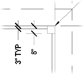
- Add another dimension measuring the width of the horizontal handrail, and add the text TYP after the dimension text, as shown in Figure 12.66.
FIGURE 12.66 The handrail dimension after adding the TYP text
NOTE he abbreviation TYP stands for typical; it tells someone reading your plans that all handrails are 3″ in width unless designated otherwise. Refer to the “Editing Dimension Text Content” section earlier in this chapter if you need a refresher on modifying dimension text. - Repeat step 9, and add the TYP abbreviation to the 4″ dimension in the upper-right corner of the bathroom.
This tells someone reading the plans for your cabin that all interior walls are 4″ in width unless designated otherwise.
- Make any adjustments necessary to make the drawing readable, and then save the drawing as I12A-FPLAYO.dwg (M12A-FPLAYO.dwg).
This concludes the exercises for dimensions in this chapter. Working successfully with dimensions in your drawing requires an investment of time to become familiar with the commands and settings that control how dimensions appear, how they are placed in the drawing, and how they are modified. The exercises in this chapter have led you through the basics of the dimensioning process. For a more in-depth discussion of dimensions, refer to Mastering AutoCAD 2013 and AutoCAD LT 2013 by George Omura (Wiley, 2012), or visit this book's website at www.thecadgeek.com or www.sybex.com/go/autocad2013ner for additional resources.
The next chapter will introduce you to external references, which can be used to view a drawing from within another drawing.
If You Would Like More Practice…
In the first practice exercise, you'll get a chance to use the dimensioning tools that you just learned. After that is a short exercise that shows a technique for incorporating centerlines into dimensions, and finally some guiding principles for further exercises.
Dimensioning the Garage Addition
Try dimensioning the garage addition to the cabin (04A-FPGARG.dwg) that was shown at the end of Chapter 4, “Developing Drawing Strategies: Part 1.” Use the same techniques and standards of dimensioning that you used in this chapter to dimension the cabin; use the DIMS-PLAN dimension style you set up and used in this chapter.
- Open 04A-FPGARG.dwg.
- Use the DesignCenter to bring over the following:
- A-DIMS-PLAN dimension style
- A-DIMS text style
- A-DIMS-MLDR multileader style
- A-ANNO-DIMS layer
- Dimension to the outside edges of exterior walls, the edges of the openings, and the centerlines of interior walls.
- Drag an A-ROOM-IDEN block and a room label from the cabin drawing into the garage drawing, and then copy and modify them as required.
- If the leader does not display properly, check the Overall Scale value in the Properties panel and make sure it is set to 64 (70).
When you're finished, the drawing should look similar to Figure 12.67.
- When you're finished, save this drawing as 12A-FPGARG.dwg.
Dimensioning to a Centerline
This exercise will show you how to use centerlines as replacements for extension lines in dimensions. I'll use as many of the default settings for text styles, dimension styles, units, and so forth as I can to give you a look at what out-of the-box, or vanilla, AutoCAD looks like. The drawing you'll make is similar to the one you made in Chapter 2, “Learning Basic Commands to Get Started,” but you know so much more now:
- Choose Application menu New Drawing. Then, in the Create New Drawing dialog box, select the acad.dwt template.
- Start the RECTANG command, and click a point in the lower-left quadrant of the drawing area.
FIGURE 12.67 The walkway and garage dimensioned
- For the second point, enter @6,2.
- Use the Zoom Extents tool, and then zoom out a bit.
- Pan to move the new rectangle down a little (see Figure 12.68).
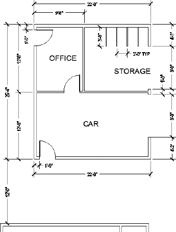

FIGURE 12.68 The rectangle after panning down
You want to dimension from the upper-left corner of the rectangle to the center of the upper horizontal line and then to the upper-right corner. You'll select the Dimension tool from the menu bar and use the default dimension settings:
- Create a new layer called A-ANNO-DIMS, accept the White color, and make A-ANNO-DIMS current.
- Set the Endpoint and Midpoint osnaps to be running, and then click the Linear button in the Dimensions panel or in the Annotation panel under the Home tab.
- Click the upper-left corner of the rectangle, and then click the midpoint of the upper horizontal line of the rectangle.
- Drag the dimension line up to a point about 1 unit above the upper line of the rectangle, and click.
This places the first dimension.
- Click the dimension to make grips appear.
- Click the grip that is at the midpoint of the upper horizontal line of the rectangle and, with Polar Tracking on, drag it down to a point below the rectangle.
- Press Esc to deselect the dimension.
- Click the Continue button, and select the upper-right corner of the rectangle.
Doing so places the second dimension.
- Press Esc to end the command.
- On the Home tab Properties panel, open the Linetype drop-down list and select Other.
- In the Linetype Manager dialog box, click the Load button.
- In the Load Or Reload Linetypes dialog box, scroll down, find and click Center2, and then click OK.
The Center2 linetype now appears in the Linetype Manager dialog box.
- Click OK.
- Double-click the left dimension to open the Properties palette.
- In the Lines & Arrows rollout, click Ext Line 2 Linetype.
- Open the drop-down list, and select Center2.
- Press Esc to deselect the dimension.
- Select the right dimension.
- On the Properties palette, return to the Lines & Arrows rollout and click Ext Line 1 Linetype.
- Open the drop-down list and select Center2.
- Press Esc to close the Properties palette.
Now there is a centerline through the rectangle that's part of the dimensions. As a final touch, you'll put a centerline symbol at the top of the centerline by using the MTEXT command:
- Start the MTEXT (Multiline Text) command, and make a small defining window somewhere in a blank portion of the drawing area.
- Expand the Symbol tool found on the contextual Text Editor Ribbon tab, and select Center Line.
A centerline symbol now appears in the Multiline Text Editor.
- Highlight it, and change its height from 0.2000 to 0.4000 in the Text Height text box in the Text Style panel, as shown in Figure 12.69.
- With the text still highlighted, click the Justification button in the Paragraph panel.

FIGURE 12.69 Changing the height of the centerline symbol
From the fly-out menu that appears, click Bottom Center (see Figure 12.70).
FIGURE 12.70 Setting the Justification for the centerline symbol
-
 Click the Close Text Editor button in the Close panel to execute the changes and close the Multiline Text tab.
 - Click the centerline symbol to activate the grips.
- Click the lower-middle grip, and then click the upper end of the centerline.
This locates the symbol properly.
- Turn off running osnaps, be sure Polar Tracking is on, and click the same grip as you did in the previous step.
- Move the symbol up slightly to create a space between it and the centerline (see Figure 12.71).
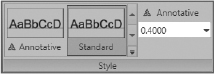
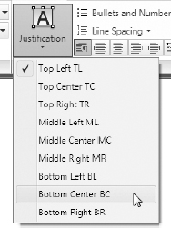
This completes the exercise. You can save the drawing if you wish.
Completing Further Exercises
Use the skills you've learned in this chapter to do the following:
- Set up a dimension style for your own use.
- Dimension a drawing as you would in your own profession or trade.
- Dimension any of the other drawings offered in previous chapters, such as the block, the gasket, or the parking lot.
- Add dimensions to the cabin elevations.
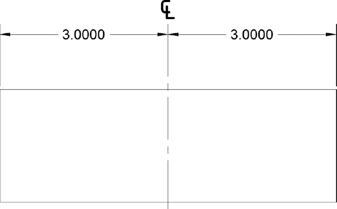
FIGURE 12.71 The centerline symbol and a centerline used as part of two dimensions
Are You Experienced?
Now you can…
- Create a new dimension style
- Place vertical and horizontal dimensions in a drawing
- Use radial, aligned, and angular dimensions
- Create a multileader style
- Create multileader lines for notes
- Modify dimension text
- Override a dimension style
- Modify a dimension style