
CHAPTER 16
Creating 3D Geometry
Nothing in Autodesk® AutoCAD® software is quite as fascinating as drawing in 3D. In addition to being interesting to create, 3D models are incredibly valuable project assets. Today's architects and engineers are increasingly using AutoCAD 3D features not only to communicate designs with clients but also as a design and analysis tool. This chapter covers 3D modeling, and the next chapter introduces materials and rendering.
Autodesk® AutoCAD LT® software has a few 3D viewing tools but none of the 3D solid-modeling tools that AutoCAD supports. Therefore, this chapter doesn't apply to AutoCAD LT.
Constructing a 3D model of a building requires many of the tools that you've been using throughout this book and some new ones that you'll be introduced to in this chapter. Your competence in using the basic drawing, editing, and display commands is critical to your successful study of 3D for two reasons:
- Drawing in 3D can seem more complex and difficult than drawing in 2D, and it can be frustrating until you get used to it. If you aren't familiar with the basic commands, you'll become that much more frustrated.
- Accuracy is critical in 3D drawing. The effect of errors is compounded, so you must be in the habit of using tools, such as the osnap modes, to maximize your precision.
Many 3D software packages are on the market today, and some are better for drawing buildings than others. Often, because of the precision that AutoCAD provides, a 3D DWG file is exported to one of these specialized 3D packages for further work, after being laid out in AutoCAD. Two other Autodesk products, Autodesk® 3ds Max® and Autodesk® 3ds Max® Design, are designed to work with AutoCAD DWG files and maintain a constant link with AutoCAD-produced files.
In this chapter, you'll look at the basic techniques of solid modeling and a couple of tools used in mesh and surface modeling. In the process, you'll learn some techniques for viewing a 3D model.
In this chapter, you will learn to
- Set up a 3D workspace, and navigate a 3D environment
- Use the Polysolid tool, and Boolean functions.
- Extrude 2D objects, and create 3D surfaces
Modeling in 3D
You'll begin by building a 3D model of the cabin, using several techniques for creating 3D solids and surfaces. When you use solid-modeling tools, the objects you create are solid, like lumps of clay. They can be added together or subtracted from one another to form more-complex shapes. By contrast, 3D surfaces are composites of two-dimensional planes that stretch over a frame of lines the way a tent surface stretches over the frame inside.
As you construct these 3D objects, you'll become more familiar with the user coordinate system (UCS), learn how it's used with 3D, and begin using the basic methods of viewing a 3D model.
Setting Up the 3D Workspace and Environment
So far, you've been using the Drafting & Annotation workspace to create your drawings. Your first task in transitioning into 3D begins by switching to a new workspace for working in 3D and changing how AutoCAD displays the available tools.
Follow these steps to switch the workspace:
- Open the I14A-FPLAYO.dwg (M14A-FPLAYO.dwg) file you created previously, or download it from this chapter's website found at www.sybex.com/go/autocad2013ner or www.thecadgeek.com.
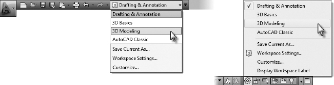
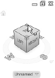
Switch to the 3D Modeling workspace by using the Workspace drop-down list on the Quick Access toolbar (see the left image in Figure 16.1).
Alternatively, the gear icon on the status bar at the bottom of the Application window may also be used to change workspaces (see the right image in Figure 16.1).
FIGURE 16.1 Switching to the 3D Modeling workspace from the Quick Access toolbar (left) and from the status bar (right)
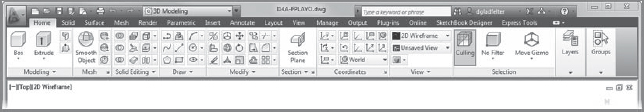
Switching to the 3D Modeling workspace updates the AutoCAD user interface, deemphasizing the 2D drafting tools used until this point and placing emphasis on the 3D modeling toolset (see Figure 16.2). While many of the 2D drafting tools have been deemphasized and/or removed from the Ribbon, it's important to note that all AutoCAD commands are still available from the command line. Likewise, it's always possible to restore the complete 2D drafting toolset by switching back to the Drafting & Annotation workspace.
FIGURE 16.2 The 3D Modeling workspace
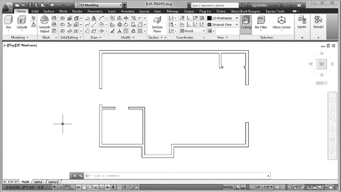
Zoom in to the floor plan, make the A-WALL layer current, and freeze all other layers.
Your drawing and AutoCAD setup will look like Figure 16.3.
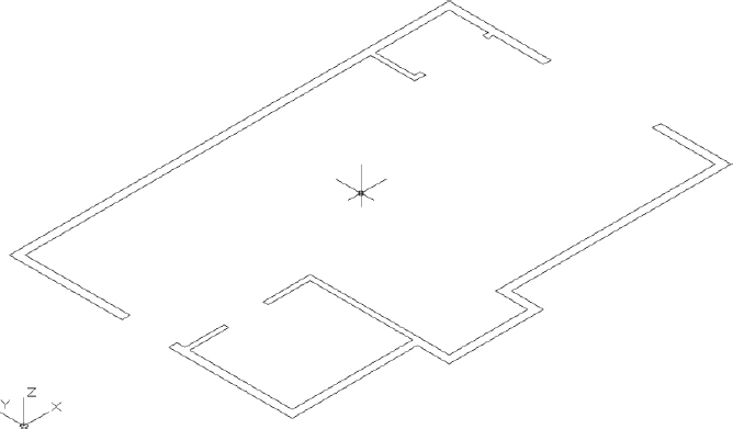
FIGURE 16.3 I14A-FPLAYO.dwg (M14A-FPLAYO.dwg) with all layers turned off except A-WALL
 If the UCS icon isn't visible on your screen, click the View tab and then click the Show UCS Icon button on the Coordinates panel.
You'll use the UCS icon in a moment, but for now keep an eye on it as the drawing changes. Remember that the icon's arrows indicate the positive direction for the x-, y-, and (in 3D) z-axes.
THINKING IN 3D
Try to start thinking of your model in three dimensions. The entire drawing is on a flat plane parallel to the monitor screen. When you add elements in the third dimension, they project straight out of the screen toward you if they have a positive dimension, and straight through the screen if they have a negative dimension. The line of direction is perpendicular to the plane of the screen and is called the z-axis. You're already familiar with the x- and y-axes, which run left and right, and up and down, respectively. Think of the z-axis as running into and out of the screen.
Now you'll use the in-canvas viewport controls to change the view from a plan view of the drawing—looking straight down at it—to one in which you're looking down at it from an angle. There are several preselected viewpoints, and here you'll switch to one of them.
The in-canvas viewport controls are composed of three bracketed menus in the upper-left corner of the drawing window. Starting from the left, these menus are as follows:
- Viewport Control
- View Controls
- Visual Style Control
You'll use the View Controls menu to change the angle in which the drawing is displayed.
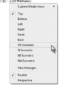
Using the in-canvas viewport controls, click the View Controls menu, currently displayed as [Top], and choose SW Isometric, as shown in Figure 16.4.
The view changes to look like Figure 16.5. Notice how the UCS icon has altered with the change of view. The X and Y arrows still run parallel to the side and front of the cabin, but the icon and the floor plan are now at an angle to the screen, and the z-axis is visible. The crosshair cursor is now colored and also displays the z-axis.
FIGURE 16.4 Select the Southwest Isometric view from the in-canvas viewport control's View Controls menu.
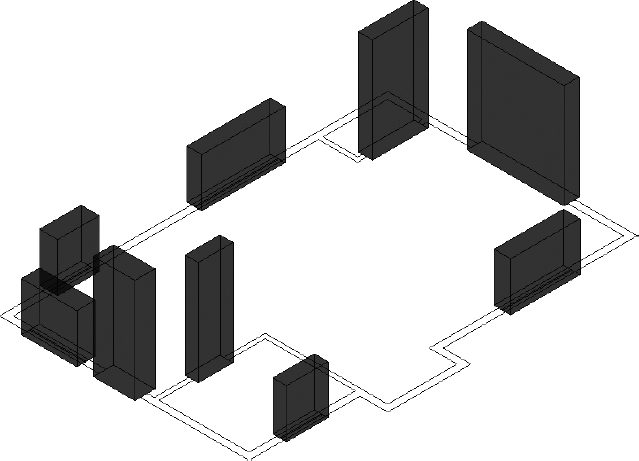
FIGURE 16.5 The walls as displayed from the Southwest Isometric view
Visual styles allow a 3D model to display in several different ways: with nonvisible edges hidden, with materials applied, or even transparently. The most appropriate visual style is often dictated by the task at hand, the context of which will be established in the succeeding exercises.
Currently, the most basic of these visual styles, 2D Wireframe, is in use. To get started, you'll change this to one of the 3D visual styles included with the product.
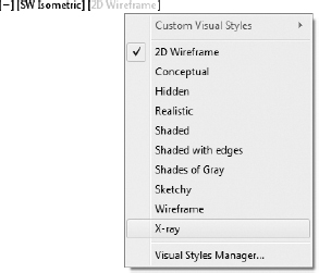
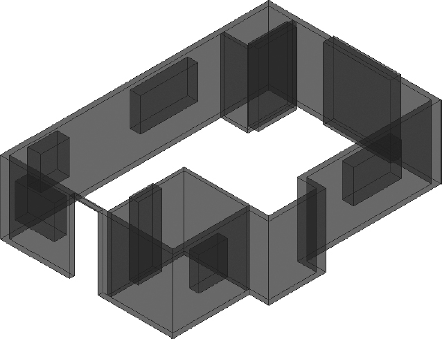
Returning to the in-canvas viewport controls, click the Visual Style Controls menu, currently displayed as [2D Wireframe], and select X-Ray (see Figure 16.6).
FIGURE 16.6 Selecting the X-Ray visual style
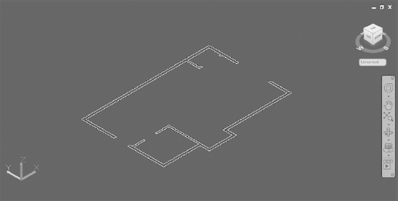
The drawing area takes on a dark gray background, and the UCS icon changes to a chunkier, three-color appearance. Also note how the position of the ViewCube in the upper-right corner reflects the current orientation of your drawing (see Figure 16.7). The ViewCube is a navigation tool covered later in this chapter.
Save your drawing as I16-01-ViewSetup.dwg (M16-01-ViewSetup.dwg).
FIGURE 16.7 The drawing using the X-Ray visual style
![]() NOTE A common convention in 3D graphics is to color vectors or other axes to indicate elements so that red indicates the x-axis, green indicates the y-axis, and blue indicates the z-axis. The phrase used to remember this scheme is RGB = XYZ. You'll see this convention used several times in this and the next chapter.
NOTE A common convention in 3D graphics is to color vectors or other axes to indicate elements so that red indicates the x-axis, green indicates the y-axis, and blue indicates the z-axis. The phrase used to remember this scheme is RGB = XYZ. You'll see this convention used several times in this and the next chapter.
Making the Walls
The main task ahead is to create a 3D model of the cabin. You'll use solid elements for the cabin's walls, doors, windows, floor, decks, and steps. You'll learn several ways of viewing your work as you progress. To make the walls, you'll start with the polysolid object and then, like a sculptor, remove everything that isn't an interior or exterior wall from the polysolid. The elements to be removed are the void spaces for the doors and windows.
Creating the Exterior Walls
To make the exterior walls, follow these steps:
- Continue using I16-01-ViewSetup.dwg (M16-01-ViewSetup.dwg), or open it if it is not already open.
- Set the Endpoint osnap to be running.
- Create a new layer called A-WALL-EXTR-3DOB, assign it color 22, and make it current.
 Click the Polysolid tool on the Primitive panel of the Solid tab.
AutoCAD may pause briefly as it loads the 3D-specific applications.
At the _Polysolid 0'-4", Width = 0'-0 1/4", Justification = Center Specify start point or [Object/Height/Width/Justify] <Object>: prompt, enter H
 7'7-1/4" (2318) to set the object height to
  (2318 mm).
This is the height where the inside faces of the exterior walls meet the roof.
The exterior walls are 6″ (150 mm) thick, so the polysolid object should be 6″ (150 mm) thick as well.
Enter W
and then 6 (150) at the Specify width < 0'-01/4"NF: prompt.The Justification option determines the side of the polysolid on which you will pick the endpoints. You will be picking the outside lines of the cabin in a counterclockwise order, so the justification must be set to Right.
- Enter J to choose Justify from the command line, and then enter R to specify a Right justification.
You're now ready to begin creating the walls.
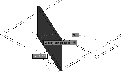
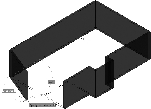
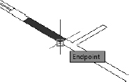
- Use the Endpoint osnap to select the corner for the exterior wall of the cabin nearest to the bottom of the screen, and then move the cursor.
The first wall appears, and it is tied to the cursor, as shown in Figure 16.8.
FIGURE 16.8 Starting the first polysolid wall
Moving in the counterclockwise direction, click each of the endpoints along the outside perimeter of the cabin until only one segment separates the last segment from the first.
Your drawing should look like Figure 16.9.
- Right-click, and choose Close from the context menu to close the polysolid.
- Save your drawing as I16-02-ExteriorWalls.dwg (M16-02-ExteriorWalls.dwg).
Adding the Interior Walls
The interior cabin walls are thinner than the exterior walls and will probably have a different material assigned to them. You will make a new layer for these walls and change the polysolid parameters:
- Continue using I16-02-ExteriorWalls.dwg (M16-02-ExteriorWalls.dwg), or open it if it is not already open.
Create a new layer called A-WALL-INTR-3DOB, assign it color 44, and make it the current layer.
FIGURE 16.9 The exterior walls drawn with polysolids
Click the upper corner of the ViewCube to change your view to a North East orientation (see Figure 16.10), and zoom in to the lower-left corner of the cabin so that you can see the bathroom walls.
FIGURE 16.10 Using the ViewCube to change the view orientation
Start the POLYSOLID command again.
You can also start the POLYSOLID command by entering PSOLID
 .
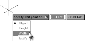
.- Press the down-arrow on the keyboard to expose the context menu at the cursor, and then click the Width option, as shown in Figure 16.11.
- Enter 4(100) to change the width to 4″ (100 mm).
- Starting with the interior endpoint of the inside wall nearest to the back door, draw the two walls that enclose the bathroom.
FIGURE 16.11 Choosing the Width option from the context menu
Right-click, and choose Enter to terminate the command.
If you have trouble clicking the correct endpoints, temporarily freeze the A-WALL-EXTR-3DOB layer, create the new wall, and then thaw the layer.
Press the spacebar to restart the command, and then draw the two walls that surround the closet, starting at the endpoint that is farthest from the sliding glass door.
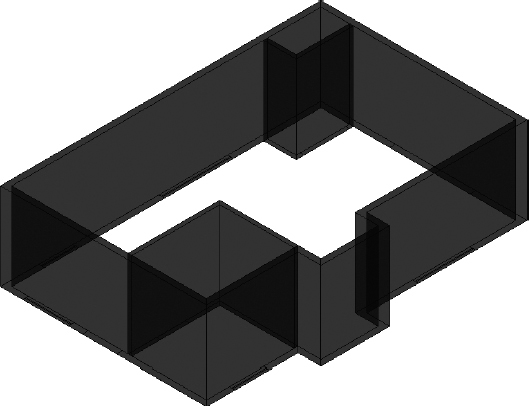
Make sure that the walls are justified properly, and then zoom to the drawing's extents. Your drawing should look similar to Figure 16.12.
Save your drawing as I16-03-InteriorWalls.dwg (M16-03-InteriorWalls.dwg).
FIGURE 16.12 The cabin with all the walls drawn as polysolids
Creating the Door and Window Block-Outs
Before you add the geometry for the doors and windows, you must make the openings in the walls. You will accomplish this by using the Boolean tools, which can create a single object from the volumes of two overlapping objects called operands. There are three Boolean functions:
Union Union combines the two volumes.
Subtraction Subtraction deletes one object and the overlapping volume shared with the other.
Intersection Intersection deletes both objects, leaving only the shared volume behind.
For the doors and windows, you will make solid boxes the size of the openings. You'll then use the Subtract command to create voids by removing the boxes as well as the volume they share with the walls. The boxes act as block-outs—volumes that are to be deleted—and their only function is to help delete part of the polysolid wall.
Creating the Door Block-Outs
Follow these steps to make the door block-outs:
- Continue using I16-03-InteriorWalls.dwg (M16-03-InteriorWalls.dwg), or open it if it is not already open.
- Make a new layer named A-DOOR-3DOB, apply color 100, and set it as the current layer.
Freeze the two A-WALL 3DOB layers, and thaw the A-GLAZ layer.
 NOTE See Figure 10.1 in Chapter 10, “Generating Elevations,” for the window elevations above the floor.
- Click the upper corner of the ViewCube to change from the current northeast view to a southwest orientation.
- Zoom in to the cabin so that you can see the back door and the kitchen window.
 Click the Box button in the Modeling panel of the Home Ribbon tab, or enter BOX at the command prompt.
If the Box tool is not shown, click the down-arrow below the tool on the far-left side of the panel and choose it from the fly-out menu. You will be making a block-out that will act as the operand that is removed from the polysolid.
Boxes (as well as cylinders, cones, and the other 3D objects on the fly-out) are known as primitives, and they are often used as the building blocks of more-complex objects.
The box object requires three items of information to be constructed: two points that define the opposing corners of the object's footprint, and a height value.
At the prompts, click two opposite corners of the back door opening, as shown in Figure 16.13.
FIGURE 16.13 Defining the footprint of the back door
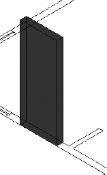
At the Specify height or [2Point]: prompt, enter 7'6
(2286). The box appears in place (see Figure 16.14).FIGURE 16.14 The first door operand created in place
When I instruct you to pick an object when working in 3D, you need to click an edge of the object or a line that helps define the object. If you try to select a surface, the selection may not be recognized.
Repeat steps 6–8 to create the block-outs for two internal doors and the sliding glass door.
When using the Boolean functions, it's best not to have a situation where the two operands have coplanar faces.
Select the box at the back door.
The box's grips appear all around the base and at a single location at the top. Dragging the triangular grips changes the lengths of the sides of the box but doesn't change the angles between the sides. The square grips move the corners of the box or the box itself, and the single top grip changes the box's height.
Click the triangular grip on the front of the box, and drag it forward to pull the front of the box out from the front of the cabin.
It doesn't have to be a great distance, just enough so that the box and the frozen polysolid don't share the same plane.
Drag the rear triangular grip backward, and position it off the inside of the exterior wall.
The base of the door should look similar to Figure 16.15.
FIGURE 16.15 The base of the door after dragging the grips
Repeat the process for the other three door block-outs so that each is thicker than its associated opening.
Your screen should look similar to Figure 16.16.
- Save your drawing as I16-04-DoorBlockOut.dwg (M16-04-DoorBlockOut.dwg).
FIGURE 16.16 All the thick door block-outs in place
Creating the Window Block-Outs
As you might expect, making the window block-outs will be just like making the doorway openings. The only difference is that the bottoms of the window openings sit at a different height above the 2D floor plan. Here are the steps:
- Continue using I16-04-DoorBlockOut.dwg (M16-04-DoorBlockOut.dwg), or open it if it's not already open.
Using the same procedure as in the previous section, create the boxes for all the window block-outs, with each box set to 3′-6″ (1067 mm) tall.
 TIP After you make the first window box, the default height for the BOX command is the correct height for the remaining windows. When prompted for the height, just press the spacebar or .
Change the thicknesses of the boxes so that they overlap the thickness of the outside walls.
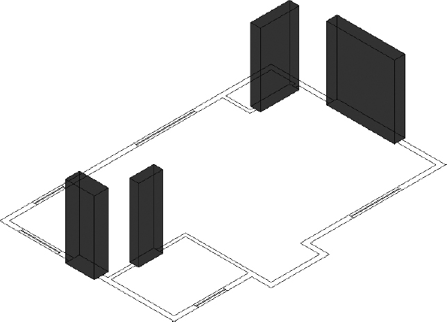
Your drawing should look like Figure 16.17.
FIGURE 16.17 The drawing with all the block-outs in place
- Save your drawing as I16-05-WindowBlockOut.dwg (M16-05-WindowBlockOut.dwg).
Moving and Rotating in 3D
When you moved objects in the 2D portion of this book, terms such as left and right or up and down were acceptable to use because all movements were associated with the sides of the drawing area. Even when you rotated the views in Chapter 10, it was so that you could relate movements to the screen more easily. When working in 3D, however, these terms are no longer easily translated from your intent to proper movement on the screen. Let's take the back door block-out, for example. If I told you to move it forward, would that mean into the cabin, away from the cabin, or toward the bottom of the screen? You can see what the problem is. When the viewpoint is significantly different from what you may expect, say, from the bottom or the back, then front or back may be even more confusing.
Using the First Right-Hand Rule
To help you stay oriented in 3D space, the UCS becomes more important. Each colored axis of the UCS icon points in the positive direction for that particular axis. To understand whether a movement, particularly in the z-axis, is in the positive direction, you should be familiar with the first of two right-hand rules.
The first right-hand rule relates your hand to the UCS and helps clarify the axis directions. Start by extending the thumb and index finger on your right hand to form an L-shape. Then project your middle finger perpendicular to your palm, as shown in Figure 16.18. The rule states: When your thumb is pointing in the positive X direction and your index finger is pointing in the positive Y direction, your middle finger must be pointing in the positive Z direction.
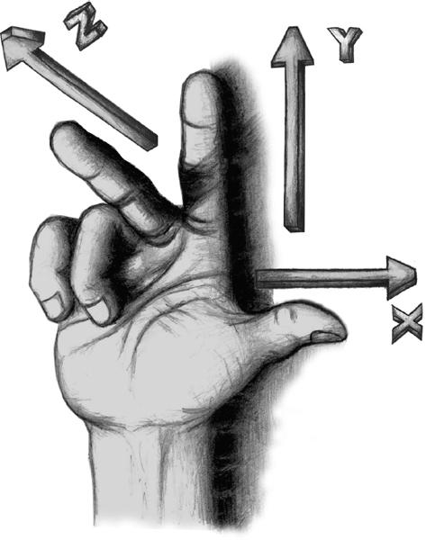
FIGURE 16.18 Use the first right-hand rule to identify x-, y-, and z-axes.
To apply this to the window block-outs in our cabin example, compare your right hand to the UCS icon in the drawing area. With your thumb pointing toward the cabin, and your index finger pointing away from the cabin and to the left, your middle finger then points toward the top of the screen. This indicates that the window block-outs, which are currently resting on the ground plane with the door block-out, need to be moved in the positive Z direction.
- Continue using I16-05-WindowBlockOut.dwg (M16-05-WindowBlockOut.dwg), or open it if it's not already open.
 Click the 3D Move tool in the Modify panel on the Home tab.
With the 3D Move tool, objects are moved using the Move grip tool, which looks similar to the UCS icon.
- At the Select objects: prompt, select the bathroom window block-out and then press to end the selection process.
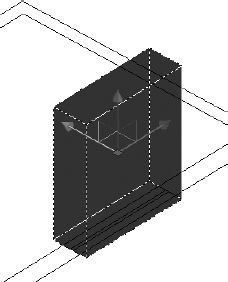
The Move grip tool appears at the center of the box, as shown in Figure 16.19. Note the different-colored arrows that make up the 3D move tool: the color of each arrow matches the RGB = XYZ convention used for the 3D UCS icon.
FIGURE 16.19 The Move grip tool at the center of the box
- Move the cursor over each of the colored axes of the Move grip tool.
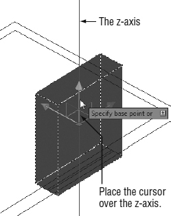
Notice that the axis turns yellow to indicate that it is current, and a vector appears in line with the axis, as shown in Figure 16.20. When a vector is visible, all movements, whether indicated with the cursor and a mouse click or with input from the keyboard, are constrained to the axis indicated.
FIGURE 16.20 The z-axis vector indicating that moves are restricted to the z-axis
- Move the cursor over the blue z-axis.
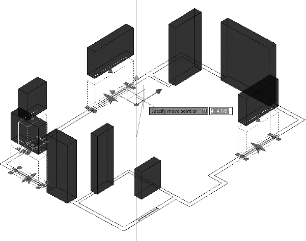
When the axis vector appears, click and move the box in the positive Z direction, and enter 2'11
(889).The box moves 2′-11″ (889 mm) above the wall lines.
TIP You can also use the standard Move tool and enter @0,0,2′11 (@0,0,889) to move the box 2′-11″ (889 mm) along the z-axis.- Start the 3D Move tool again, and this time pick the four remaining window block-outs.
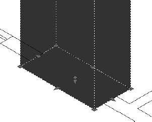
Move the cursor directly above the Move grip tool, and then click and drag the z-axis.
Notice that all four boxes are moving, and each leaves a ghosted version of itself at its original location (see Figure 16.21).
- Enter 2'11 (889) to move the selected block-outs.
A move operation in a 3D view can sometimes be deceiving:
Save your drawing as I16-06-ElevateWindows.dwg (M16-06-ElevateWindows.dwg).
FIGURE 16.21 Move the remaining block-outs 2′-11″ (889 mm) in the positive Z direction.
Cutting the Openings
You are ready to start the Boolean processes and cut the openings in the walls. When prompted to select an object, be sure to click an edge of the 3D objects and not a face, or the selection may not be successful.
- Continue using I16-06-ElevateWindows.dwg (M16-06-ElevateWindows.dwg), or open it if it's not already open.
- Thaw the A-WALL-EXTR-3DOB and A-WALL-INTR-3DOB layers, and freeze the A-GLAZ layer.
 Click the Subtract button on the Solid Editing panel of the Home tab, or enter SUBTRACT.
At the Select solids and regions to subtract from… Select objects: prompt, select the exterior wall and then press
to end the selection process.You can perform the Boolean functions on several objects at one time, but first you will do it to only one.
At the Select solids, surfaces and regions to subtract… Select objects: prompt, select the back door and then press
.The door block-out, and the volume that it shared with the wall, are subtracted from the exterior wall (see Figure 16.22).
FIGURE 16.22 The back door subtracted from the exterior wall of the cabin
Start the SUBTRACT command again, and select the exterior wall again.
TIP If you have trouble seeing the window block-outs, temporarily switch to the 3D Wireframe visual style, execute the Boolean operation, and then switch back to the X-Ray style.- When prompted for the objects to subtract, select all the remaining exterior door and window block-outs and then press .
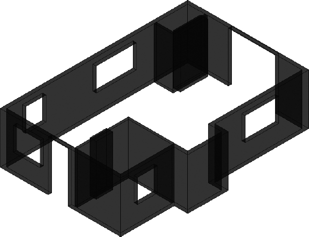
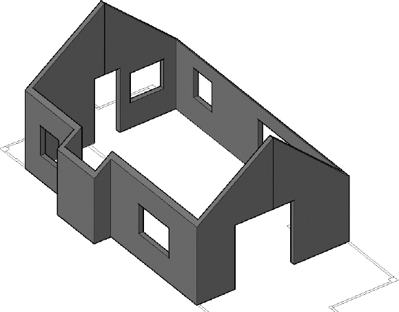
All the openings appear on the cabin's exterior walls, as shown in Figure 16.23.
FIGURE 16.23 Each of the interior and exterior openings created for the cabin
- Repeat the subtraction process on the two interior walls to remove the bathroom and closet door volumes.
- Save your drawing as I16-07-ExteriorOpenings.dwg (M16-07-ExteriorOpenings.dwg).
Creating the Floor, Foundation, and Thresholds
In designing the cabin, you didn't draw a floor, but one was implied. The three exterior doorway openings have thresholds that indicate a small change in level from the cabin floor down to the decks. You'll now create additional objects to make the floor, foundation and supports, and the thresholds. Follow these steps:
- Continue using I16-07-ExteriorOpenings.dwg (M16-07-ExteriorOpenings.dwg), or open it if it's not already open.
Continuing from the previous set of steps, open the Layer Properties Manager and do the following:
Create the following new layers:
A-DOOR-THRE-3DOB
A-FLOR-3DOB
A-FNDN-3DOB
- Make A-DOOR-THRE-3DOB current.
- Give each layer a unique color.
- Freeze the A-WALL-EXTR-3DOB and A-WALL-INTR-3DOB layers.
- Thaw the A-DECK-STRS layer.
To see where you're going, look ahead to Figure 16.26. You'll use the EXTRUDE command to create a series of solids that represent the thresholds and boxes for the steps and the floor.
To find your 3D object layers quickly in the Layer Properties Manager, try entering *3DOB in the text box in the upper-right corner.
- Zoom in on the back door opening and its threshold.
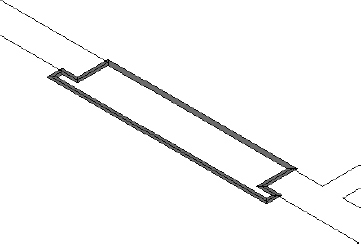
Draw a polyline around the perimeter of the threshold; use the Close option to make the last segment. The threshold extends 3″ (76 mm) beyond the door opening, and 2″ (50 mm) beyond the cabin.
For clarity only, the polyline is shown wider than necessary in Figure 16.24.
FIGURE 16.24 A polyline drawn around the perimeter of the threshold
 The Extrude tool extends a 2D object in the Z direction, creating surfaces on the newly formed sides and end caps.
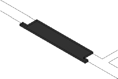
- Click the Extrude tool in the Modeling panel of the Home tab, select the threshold polyline, and then press .
At the Specify height of extrusion or [Direction/Path/Taper angle] <-1′-0″>: prompt, enter 1.05
(27).The first threshold is completed, as shown in Figure 16.25.
FIGURE 16.25 The extruded polyline
- Make a similar extruded threshold for the sliding glass door.
- Make the A-FLOR-3DOB layer current.
- To create the floor, first draw a polyline around the inside perimeter of the cabin, ignoring the interior walls and thresholds.
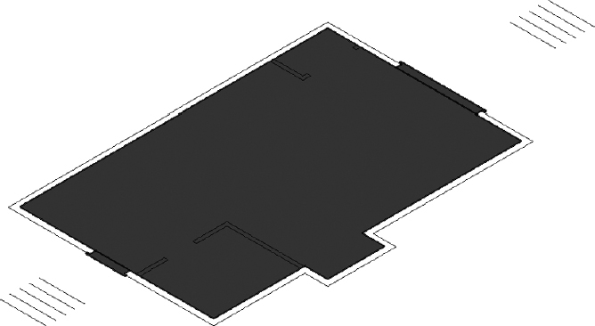
- Start the EXTRUDE command, select the floor polyline, and then extrude it 1″ (25 mm), as shown in Figure 16.26.
- Save your drawing as I16-08-Thresholds.dwg (M16-08-Thresholds.dwg).
Creating the Foundation and Supports
The cabin's foundation is a concrete slab 18″ (457 mm) thick that sits directly on the ground. The foundation supports the structure except where the pop-out projects out from the side wall. At the outside corners of each deck are concrete support posts. All the objects are placed on the 3D-Foundation layer.
Continue using I16-08-Thresholds.dwg (M16-08-Thresholds.dwg), or open it if it's not already open.
FIGURE 16.26 The 3D floor with the thresholds
- Make the A-FNDN-3DOB layer current, and thaw the A-DECK layer.
- Freeze the A-FLOR-3DOB and A-DOOR-THRE-3DOB layers.
Draw a closed polyline around the outside perimeter of the cabin, making sure you span the pop-out area as if it didn't exist.
Alternatively, you could use the Rectangle (RECTANG) command.
- Extrude the polyline 18″ (457 mm) in the negative Z direction. You can do this with Dynamic Input active by dragging the extrusion in the negative direction and entering 18 (457), or by dragging it in the positive direction and entering −18 (−457).
Using the Rectangle (RECTANG) command, draw a 12″×12″ (305 mm×305 mm) rectangle at each of the four outside corners of the decks.
The outside corner of each rectangle should match the outside corner of each deck post corner.
- Start the EXTRUDE command, select all four rectangles, and then extrude them 2′-10″ (864 mm) in the negative Z direction.
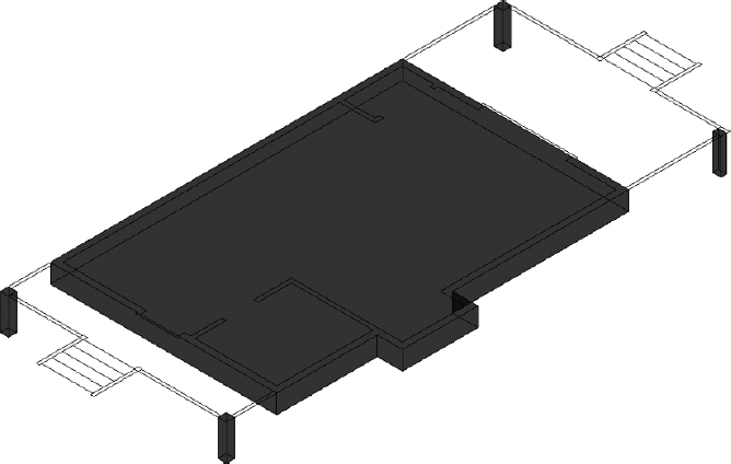
When you're finished, the foundation and supports should look like Figure 16.27.
FIGURE 16.27 The foundation and supports
- Save your drawing as I16-09-FoundationSupport.dwg (M16-09-FoundationSupport.dwg).
![]() TIP Similar to the way you used Quick Filter to create a Wblock (WBLOCK) earlier in the book, try using the Quick Select button on the Properties palette to select the four foundation posts.
TIP Similar to the way you used Quick Filter to create a Wblock (WBLOCK) earlier in the book, try using the Quick Select button on the Properties palette to select the four foundation posts.
Building the Windows
Now that the openings are in place and the foundation is complete, you just need to build the geometry for the doors and windows. These can be as complete as you like, with sills, drip grooves, tapered panels, kick plates, and so on. For the exercise in this book, however, you'll create fairly simple frames, door panels, and glazing.
- Continue using I16-09-FoundationSupport.dwg (M16-09-FoundationSupport.dwg), or open it if it's not already open.
- Make a new layer named A-GLAZ-SILL-3DOB, and set it as the current layer.
- Freeze the A-FNDN-3DOB layer.
- Thaw the A-WALL-EXTR-3DOB layer.
- Zoom in to the kitchen window near the back door.
 Click the Allow/Disallow Dynamic UCS button in the status bar to turn on Dynamic UCS mode.
When you are in a command, Dynamic UCS causes the current UCS to adapt to the orientation of whichever face the cursor is over. This is important because, when using creation tools such as the BOX command, the footprint is made in the xy-plane, and the height is projected along the z-axis. When Dynamic UCS is active, the UCS shown at the cursor overrides the UCS shown by the UCS icon.
Start the BOX command and then move your cursor near the UCS icon.
Notice that the color-coded axes of the crosshairs match the orientation and colors (RGB = XYZ) of the UCS icon axes.
Move the cursor over the faces on the back wall of the cabin, and notice that the blue z-axis now points in the same direction as the UCS icon's y-axis.
This identifies the orientation of that particular wall's face.
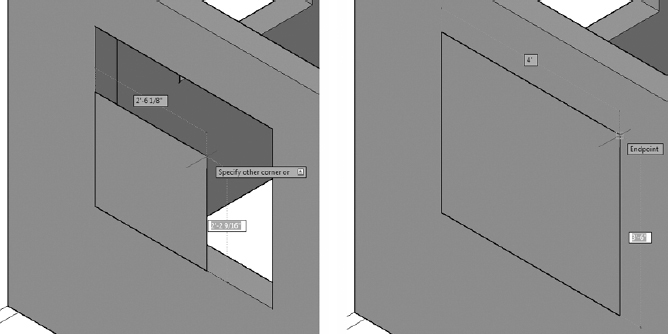
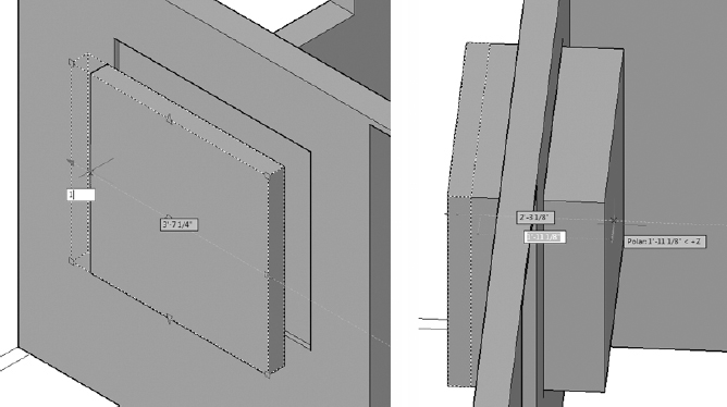
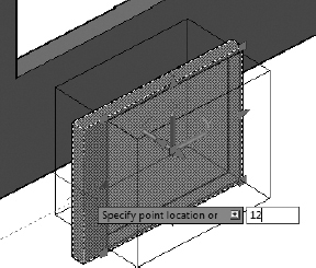
With the Endpoint osnap active, click the lower-left outside corner of the kitchen window, and then move the cursor away from that corner.
The box starts to form with its orientation parallel to the outside wall, and the UCS icon temporarily changes its orientation (see the left image of Figure 16.28).
- Click the opposite outside corner of the window for the base of the new box (see the right image of Figure 16.28).
At the Specify height or [2Point]>: prompt, move the cursor until you can see the box projecting out from the wall and then enter -4
(-100).The box's Height parameter projects it 4″ (100 mm) into the window opening. You can switch to a Wireframe visual style to see this more clearly.
FIGURE 16.28 With Dynamic UCS turned on, the box's base is oriented parallel to the wall (left), and the box's base is completed (right).
Turn off Dynamic UCS, select the box, and move it 1″ (25 mm) in the positive X direction to center it in the wall.
The box you just made will be the frame for the kitchen window. Now you need to make a block-out to subtract from the box to create the opening for the glazing.
For clarity, the illustrations for the kitchen window are shown using the Conceptual visual style.
Copy the box you just made, move it in front of the back wall, and then select the copy to expose its grips.
Use Ortho mode, keyboard input, or the Move grip tool to ensure that the box is moved along the x-axis only.
- Turn on Polar Tracking.
- Select each of the four outward-pointing triangular grips along the perimeter, and move them 1″ (25 mm) toward the inside of the box (see the left image of Figure 16.29).
Click the triangular grip on the back of the box, and drag it until the box extends all the way through the back wall (see the right image of Figure 16.29).
FIGURE 16.29 Moving the block-out's perimeter grips to shrink it slightly (left) and the box's increased depth (right)
- Using the in-canvas viewport controls, switch to the 3D Wireframe visual style and turn on the Selection Cycling tool in the status bar if it's not already on.
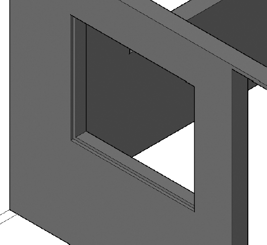
- Using the Subtract Boolean function, subtract the block-out from the frame.
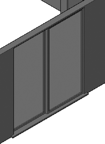
- Switch back to the Conceptual or X-Ray visual style, and your window should look similar to Figure 16.30.
Create a new layer named A-GLAZ-3DOB, give it a light blue color such as 151, and make it current.
A polyline can be drawn only in the xy-plane, but a 3D polyline can be drawn along any axis.
 Click the 3D Polyline button in the Home tab
  Draw panel, or enter 3DPOLY at the command line.
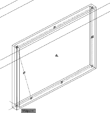
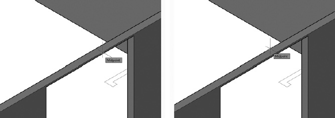
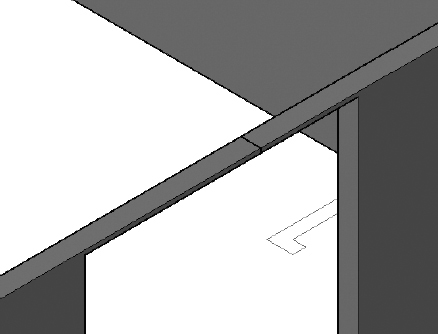
- Turn on the Midpoint running osnap, and then draw the 3D polyline by using the midpoints of the frame's four, 4″ (100 mm) wide inner corners.
Switch to the Wireframe visual style and freeze the A-WALL-EXTR-3DOB layer if you have trouble locating the midpoints.
Be sure to switch back to the Conceptual or X-Ray visual style and thaw the layer when you are finished.
FIGURE 16.30 The completed kitchen window frame
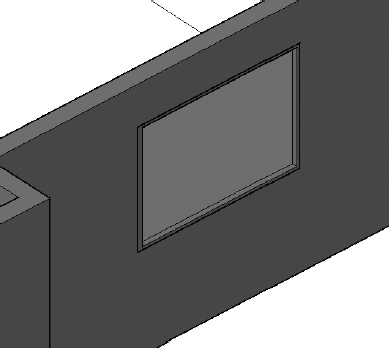
Use the Extrude tool to extrude the glazing 0.25″ (6 mm).
If you have trouble selecting the 3D Polyline, enter L
to use the Last option at the Select Objects: prompt. Your kitchen window should look like Figure 16.31.- Save your drawing as I16-10-KitchenWindow.dwg (M16-10-KitchenWindow.dwg).
Rotating in 3D (the Second Right-Hand Rule)
When you rotated objects in a 2D environment, all the rotations were perpendicular to the screen, and you never had to consider the axis around which the object was rotating. Because all 2D rotations happened in the xy-plane, the objects were rotated around the z-axis. Positive rotations were in the counterclockwise direction, and negative rotations were clockwise.
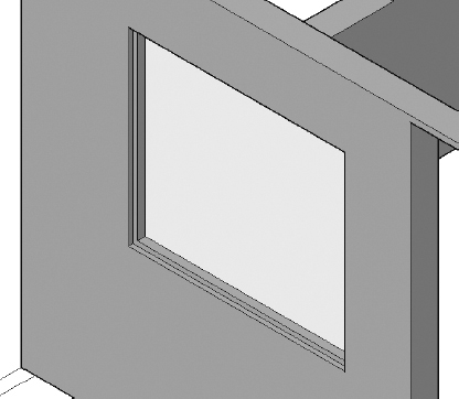
FIGURE 16.31 The completed kitchen window
In 3D, however, rotation can occur around any axis, and you need to understand whether a rotation should be in the positive or negative direction. Use the second right-hand rule to understand how the rotation direction is identified in a 3D environment. It states that if you grasp an axis with your right hand, with your thumb pointing in the positive direction, then your fingers will be curled in the positive rotation direction. Figure 16.32 illustrates this concept.

FIGURE 16.32 The right-hand rule as it applies to rotations
To rotate an object in 3D, you use the 3D Rotate tool, called a gripper, shown in Figure 16.33. It consists of three intersecting circular bands, the center of which is the pivot point of the rotation. Each band is color coded (RGB = XYZ) to identify the axis around which the objects are rotated. When you're prompted for a rotation axis, clicking the green band, for example, restricts the rotation to the y-axis.
FIGURE 16.33 The 3D Rotate gripper
Completing the Windows
When Boolean operations are used, the component objects, called operands, are not replaced with the resulting object; they just become subobjects of it. You always have the ability to edit the operands and alter the object itself. Here's how:
- Continue using I16-10-KitchenWindow.dwg (M16-10-KitchenWindow.dwg), or open it if it's not already open.
- Copy the existing window frame and glazing, and move the copy in front of the 5′-0″ (1525 mm) window on the south side of the cabin. Then zoom in to that window.
 With the two objects selected, click the 3D Rotate tool on the Home tab Modify panel.
At the Specify base point: prompt, click the endpoint of the lower corner of the frame nearest to the cabin.
The 3D Rotate gripper relocates to the specified corner.
At the Pick a rotation axis: prompt, click the blue z-axis ring.
It turns yellow to indicate that it is the currently selected axis, and a blue line is emitted from the 3D Rotate grip tool to identify the pivot axis.
Imagine your right hand gripping the blue axis line with your thumb pointing upward, as in the hand shown in Figure 16.32. This shows you that a positive rotation, the direction in which your fingers are pointing, is required to rotate the window counterclockwise.
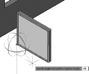
- Enter 90 at the Specify angle start point or type an angle: prompt.
The window rotates 90° (see Figure 16.34).
FIGURE 16.34 Rotating the window 90° counterclockwise
This window is currently 4′-0″ (1220 mm) wide, while the opening is 5′-0″ (1525 mm) wide. You can correct the discrepancy by editing the subobjects of the window frame. Subobjects are selected by holding the Ctrl key down while selecting an object. Follow these steps:
- Turn running object snaps off, and turn Polar Tracking on.
- Select the window frame, right-click, and choose Properties.
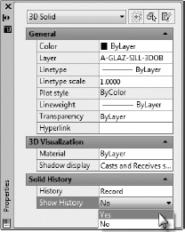
In the Solid History rollout, choose Yes for the Show History option. See Figure 16.35.
FIGURE 16.35 In the Properties palette, set the Show History property to Yes.
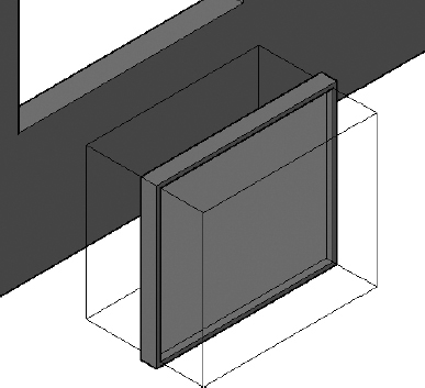
An outline of the box, used to subtract the volume for the opening, appears as shown in Figure 16.36.
FIGURE 16.36 Selecting the box from the Subtract Boolean operation
Hold the Ctrl key down, and click the window frame to select it and expose the grips.
NOTE The object that you are editing is the window frame, and the operand is the subobject. You must hold down the Ctrl key when selecting a subobject to expose its grips.- Click one of the triangular grips that control the width of the box, and drag it to make the box wider.
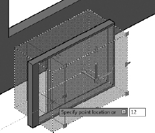
Enter 12
(305) to stretch the box 12″ (305 mm) in the X direction, as shown in Figure 16.37.The side of the window frame is now much wider than the other edges of the frame. You can fix this by adjusting the size of the box operand.
- Hold the Ctrl key down, and then click to select the box operand and expose its grips.
- Click the triangular grip on the same side that you selected for the window frame, and drag the grip to make the frame larger.
- Enter 12 (305), as shown in Figure 16.38.
FIGURE 16.38 Adjusting the size of the box from the Subtract Boolean operation
FIGURE 16.37 Adjusting the size of the window frame
The operand is extended 12″ (305 mm).
- Disable the Show History property by selecting the window and using the Properties palette.
- Change the Visual Style to Wireframe.
- Select the glazing, and then select each of the two exposed endpoints.
Use the Midpoint osnap to extend them to the new frame size (see Figure 16.39).
Finally, you need to move the new window into the opening.
Turn on the running object snaps. Then select the frame and glazing.
FIGURE 16.39 Adjusting the size of the window glazing
Use the Endpoint osnap to pick the lower-left front corner of the frame as the first move point, and the lower-left front corner of the opening as the second point.
The window is moved into place, as shown in Figure 16.40.
The frame is flush with the outside wall.
FIGURE 16.40 The new window moved into the opening
- Use the 3D Move tool to move the window 1″ (25 mm) in the positive Y direction.
Repeat the process in this section to make two of the other three rectangular windows in the cabin. Two of the windows are 3′-0″ (915 mm) wide, and you can simply copy one into the opening of the other.
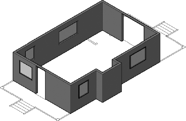
When you're finished, your drawing should look similar to Figure 16.41.
FIGURE 16.41 The cabin after all the rectangular windows and frames are finished
- Save your drawing as I16-11-FinishedWindows.dwg (M16-11-FinishedWindows.dwg).
Adding the Pivot and Bifold Doors
For this exercise, you will represent the two pivot doors with simple boxes, and the two bifold doors with extruded polylines. Later, if you choose, you can add knobs and glass panes.
- Continue using I16-11-FinishedWindows.dwg (M16-11-FinishedWindows.dwg), or open it if it's not already open.
- Set the A-DOOR-3DOB layer as current, and thaw the A-DOOR-THRE-3DOB layer.
- Zoom in to the back door.
Rather than moving the primitives as you have been doing, here you'll use Object Tracking to place the start point.
- Switch to the Wireframe visual style, turn on Object Snap Tracking mode in the status bar, and make sure the Polar Tracking and Intersection running object snaps are on as well.
- Start the BOX command.
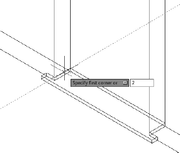
- At the Specify first corner or [Center]: prompt, place your cursor near the bottom-left outside corner of the front door, where it meets the top of the threshold, until the small cross in the intersection marker appears.
Move the cursor in the X direction until the tracking vector appears, and then enter 2
(51) to set the first corner of the door 2″ (51 mm) from the corner of the opening (see Figure 16.42).FIGURE 16.42 Locating the first corner of the door box
- Enter @2,-36 (@51,-915) to place the second point of the 3′-0″ (915 mm) door.
- Give the door a height of 7′-6″ (2286), the distance from the top of the threshold to the bottom of the door opening.
- Thaw the A-WALL-INTR-3DOB layer.
- Use a similar process to add the bathroom door, with these differences:
- The door is only 2′-6″ (762 mm) wide.
- The door is only
 (38 mm) thick.
 - The door is 7′-5″ (2261 mm) tall.
- Offset the door
 (32 mm).
 - Start or move the door 1″ (25 mm) above the bottom corner to accommodate the 1″ (25 mm) thick floor.
- Zoom in to the bifold closet doors.
- Thaw the A-DOOR layer, and change the layer of the bifold doors to A-DOOR-3DOB.
- Move the four polylines 1″ in the Z direction so that they rest at the same level as the top of the floor.
- Start the Extrude tool, and extrude each polyline 7′-5″ (2260 mm).
Zoom out, and switch to the X-Ray visual style.
Your cabin should look like Figure 16.43.
Save your drawing as I16-12-DoorModel.dwg (M16-12-DoorModel.dwg).
FIGURE 16.43 The cabin after the doors are in place
Navigating with the ViewCube
Changing the viewpoint used to view your drawings is especially important in a 3D environment because you are more likely to encounter a situation where foreground objects obscure background objects. The ViewCube, the tool in the upper-right corner of the drawing area, is used to access common views quickly, return to a saved view, or navigate freely in the drawing area.
The ViewCube (see Figure 16.44) consists of a center cube with each face labeled to identify the orthographic view that it represents. Clicking any of these labeled faces changes the viewpoint in the drawing area to display the objects from that point of view, based on the world coordinate system (WCS).
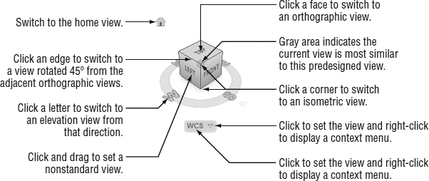
FIGURE 16.44 The functions of the ViewCube
The following examples explain how the ViewCube works:
- Clicking the ViewCube face labeled TOP changes the drawing area to display the cabin from the top, with the x-axis pointing to the right and the y-axis pointing to the top of your screen.
Clicking the face labeled FRONT changes the drawing area to display the cabin from the front, the view you designated as the south elevation, with the x-axis pointing to the right and the z-axis pointing to the top.
The orthographic views are not the only viewpoints that you can access from the ViewCube.
Clicking any corner (see the left image in Figure 16.45) changes the drawing area to display the objects from an isometric vantage point that is a combination of the three labeled faces.
FIGURE 16.45 Clicking a ViewCube corner (left) and clicking a ViewCube edge (right)
Clicking the corner at the intersection of the TOP, FRONT, and LEFT faces produces a view identical to the Southwest Isometric view you selected from the Viewpoint drop-down list.
That corner is currently gray, indicating that it is the viewpoint most similar to the current view.
- Clicking any of the edges (see the right image in Figure 16.45) changes the drawing area to display the objects rotated 45° from one of the adjacent orthographic views.
Clicking any of the ViewCube features not only changes the view but also executes a Zoom Extents, displaying all of the visible objects in the drawing area. You'll usually perform a zoom after using the ViewCube. Clicking and dragging the ViewCube changes the viewpoint freely without any constraints.
Surrounding the cube is a ring with the compass directions indicated. Clicking any of the letters switches the view in the drawing area to a view from that direction. For example, clicking the letter E on the ring displays the east elevation of the cabin. This is a view showing the 3D cabin from the east, and not the 2D east elevation that you drew. You can click and drag the ring to rotate the view in a free-form manner.
The ViewCube also provides access to the named UCSs that you created in Chapter 10 and, when a named UCS or the WCS is current, displays the name below the compass ring. Clicking the rectangle shape below the ViewCube opens a context menu (see the left image in Figure 16.46), from which you can select the current view. Right-clicking the rectangle shape opens a context menu where you can, among other things, set the ViewCube settings and designate the current view as the home view (see the right image in Figure 16.46).
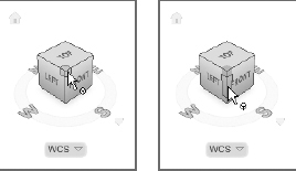
You can quickly switch to the home view by clicking the house icon, which is visible when the cursor is over the ViewCube.
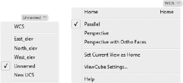
FIGURE 16.46 Selecting the current view from the ViewCube (left) and accessing the right-click context menu (right)
Switching to a predefined view is quick and can often provide the vantage point that you need, but you may need to view your objects from a specific, nonstandard location.
Holding down the Ctrl key while holding down and dragging with the scroll wheel has a function similar to dragging the ViewCube.
Adding the Sliding Door
The remaining door to add is the sliding door on the front of the cabin. Although this is a door, the procedure for creating it will be more like that for the windows you've already made. Here are the steps:
- Continue using I16-12-DoorModel.dwg (M16-12-DoorModel.dwg), or open it if it's not already open.
Click the northeast corner of the ViewCube to display the front of the cabin. Then zoom in to the front door.
Your view should look similar to Figure 16.47.
FIGURE 16.47 The view looking at the front of the cabin
- Make the A-GLAZ-SILL-3DOB layer current.
- Create a box from the right edge of the patio opening, on top of the threshold that is 3′-7″ (1092 mm) wide, 2″ (51 mm) thick.
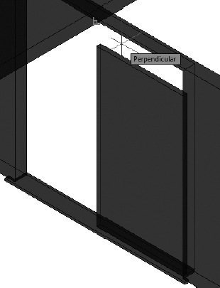
Specify the height of the door by using the Perpendicular osnap, as shown in Figure 16.48, to pick one of the upper doorframe edges.
FIGURE 16.48 Using the Perpendicular osnap to choose the door height
- With the box in place, use the 3D Move tool to position the door 1″ (25 mm) inside the right edge of the patio opening.
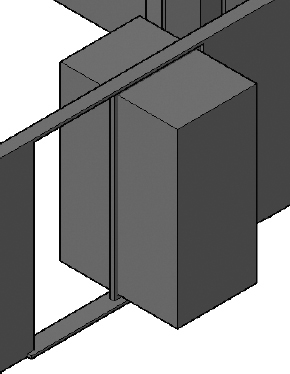
Create a block-out that is 4′ (102 mm) smaller than the width and height of the frame you just drew but significantly deeper.
Then center it on the sliding-door frame, as shown in Figure 16.49.
Some display roughness may occur where the block-out and frame meet, but this is just a function of the current visual style and the thin faces shown.
NOTE The Conceptual visual style is used in Figure 16.49 for clarity. Often, the opaque nature of the Conceptual style makes objects easier to interpret; at other times, the transparent nature of the X-Ray visual style is preferred. Your choice will likely change based on the task at hand.FIGURE 16.49 The first sliding-door frame and block-out
- Subtract the block-out from the sliding-door frame.
- Set the A-GLAZ-3DOB layer as current.
- Use the 3D Polyline tool to create the boundary to the glazing, extrude it 0.25″ (6 mm), and then center it in the frame.
- Copy the frame until it butts the opening on the left and then move it 2″ (51 mm) toward the inside of the cabin so that the two door frames are offset (see Figure 16.50).
- Save your drawing as I16-13-SlidingDoor.dwg (M16-13-SlidingDoor.dwg).
Building the Decks
You're nearly finished modeling the cabin. The next step is to make the two decks by using basic shapes and copying redundant objects. Follow these steps to create the front deck:
- Continue using I16-13-SlidingDoor.dwg (M16-13-SlidingDoor.dwg), or open it if it's not already open.
Make a new layer called A-DECK-3DOB, assign it color 240, and make it current.
FIGURE 16.50 The completed sliding door with two offset panels
- Thaw the A-FNDN-3DOB layer, and freeze the other 3DOB layers except A-DOOR-THRE-3DOB and A-WALL-EXTR-3DOB.
- Click the Box tool, and create a box to represent the floor of the deck.
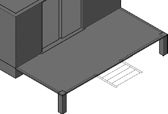
Use the Endpoint osnap to locate the two opposite corners of the deck, and then give the box a height of
 (−41 mm).
Your model should look like Figure 16.51.
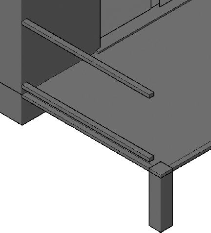
- Draw a box that follows the perimeter of the railing on the left side of the deck, and make this box 2″ (51 mm) tall.
- Move the box 4″ (102 mm) in the Z direction to represent the lower railing.
Copy this box, and move the copy 3′-2″ (965 mm) higher to represent the upper railing.
Your railings should look like those in Figure 16.52.
Repeat the process to create the two sets of railings at the front of the deck and on the left side of the stairs. Then copy both sets to the opposite side of the deck.
FIGURE 16.51 The beginning of the deck
FIGURE 16.52 The first upper and lower railings
- Switch to the right and top views with the ViewCube to check your work, and adjust the size of the railings on the right side of the steps.
Use the Zoom Previous command (Z
P) to return to the current view (see Figure 16.53).FIGURE 16.53 The railings in place and adjusted for size
 To draw the first railing post, click the down-arrow below the Box button on the Home tab Modeling panel, and choose Cylinder from the fly-out menu.
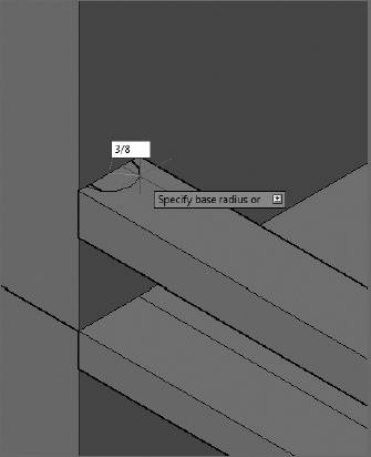
- At the Specify center point of base or: prompt, click the midpoint of the first lower railing that you drew, where it meets the exterior wall, and enter 3/8 (9.5) for the radius (see Figure 16.54).
- At the Specify height or: prompt, make sure the cursor is above the cylinder's base, and then enter 3' (914).
To fill in the row of posts, move the first post
 (92 mm) in the X direction and then copy it 20 times at 4″ (102 mm) increments in the X direction.
The first set of railing posts should look like those shown in Figure 16.55.
FIGURE 16.54 Creating the first railing post cylinder
FIGURE 16.55 The first set of railing posts
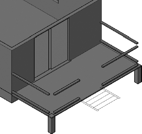
Repeat steps 12–15 to draw the posts along the front of the deck, adjusting the count and the direction appropriately. Then copy the posts from the left side of the deck to the right. Add any new post as required.
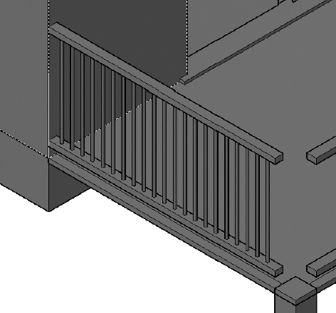
The completed railing posts should look like those shown in Figure 16.56.
FIGURE 16.56 The completed railing posts
- Zoom in to the front-left corner of the deck, where the support post sits.
Use the Box tool to draw the 8″×8″ (204 mm×204 mm) post and give it a height of 7′-8″ (2337).
You may need to adjust the height later when the roof is applied.
- Copy the post to the opposite side of the deck, and adjust the placement as necessary.
Figure 16.57 shows the two support posts in place.
FIGURE 16.57 The support posts in place
- Save your drawing as I16-14-DeckRailing.dwg (M16-14-DeckRailing.dwg).
Building the Steps
The steps, the step railings, and the posts transition from the ground level to the top of the deck. In this section, you'll build and move the stairs and create and then rotate the handrail:
- Continue using I16-14-DeckRailing.dwg (M16-14-DeckRailing.dwg), or open it if it's not already open.
- Create a new layer named A-DECK-STRS-3DOB, and make it current.
Zoom in to see the steps clearly. Then switch to the 3D Wireframe visual style.
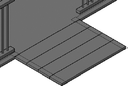
When you drew the steps in the plan view, the lines defining their width were trimmed back to the edge of the handrail. In reality, the steps extend all the way to the outside edges of the handrails.
- Use the Box tool and Object Snap Tracking or the Apparent Intersection osnap to draw the four steps. Give each box a height of
 (−41 mm).
 Switch back to the Conceptual visual style.
Your steps should look like those shown in Figure 16.58.
FIGURE 16.58 The front deck steps before setting their elevations
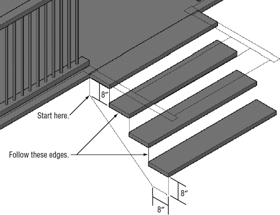
Move the step furthest from the deck 24″ (609 mm) in the negative Z direction, the second 16″ (406 mm), and the third one 8″ (203 mm).
The top step remains flush with the top of the deck.
To draw a polyline that you'll extrude to become the stringer (the support for the steps), you'll use a 3D Polyline (see Figure 16.59). Follow these steps:
- Click the 3D Polyline (3DPOLY) button in the Draw panel.
- Using the Object Snap Tracking tool, start the polyline 8″ (203 mm) below the back of the top step.
- Use the Endpoint object snap to continue drawing the stringer in a clockwise direction; snap to the corner of the top step.
- Follow the bottom and back edges of the steps until you reach the front of the bottom step.
- Continue the polyline in the negative Z direction 8″ (203 mm) and then in the negative X direction 8″ (203 mm).
Enter C
to close the polyline.FIGURE 16.59 Drawing the stringer
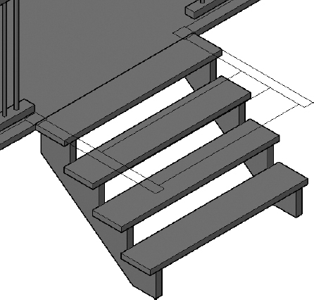
- Extrude the stringer 2″ (51 mm), and move it 2″ (51 mm) in the positive Y direction so that it's tucked under the steps a bit.
Copy or mirror the stringer to the opposite side of the steps.
The completed steps should look like those shown in Figure 16.60.
- Save your drawing as I16-15-DeckSteps.dwg (M16-15-DeckSteps.dwg).
Creating the Stair Handrails
To create the handrails for the stairs, you'll first draw the vertical posts, create a box at the end of one of one of them, and then rotate it into place. Using the Dynamic UCS tool will ensure that the box is created in the correct orientation.
- Continue using I16-15-DeckSteps.dwg (M16-15-DeckSteps.dwg), or open it if it's not already open.
Zoom in to the top of the stairs, and draw a box 3′-9″ (1143 mm) tall, using the rectangle at the end of the railing to define the footprint.
FIGURE 16.60 The completed steps
 Click the Allow/Disallow Dynamic UCS button in the status bar to turn it on.
- Start the BOX command.
- Pick a point on the front surface of the post, and then specify a 2″×2″ (51 mm×51 mm) base and a 4′-6″ (1372 mm) height for the box.
The box is created perpendicular to the front surface of the post.
- Move the handrail so that it is centered on the post and 1″ (25 mm) from the top, as shown in Figure 16.61.
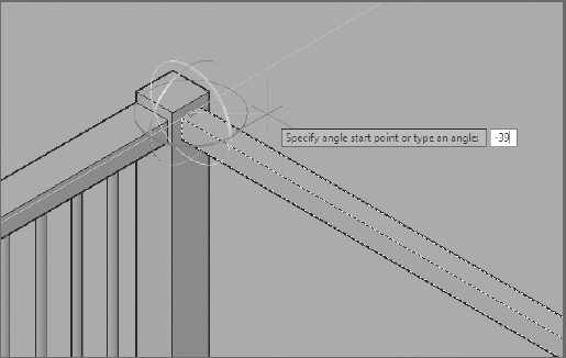
- Start the 3D Rotate tool, on the Modify panel of the Home tab, and select the handrail.
- At the Specify base point: prompt, pick the midpoint of the handrail where it meets the post.
At the Pick rotation axis: prompt, click the green y-axis ring. Then, at the Specify angle start point or type an angle: prompt, enter -39
as shown in Figure 16.62.The handrail rotates into place.
The last items to build for this handrail are the 1″ (25 mm) posts that support it.
FIGURE 16.61 The box drawn perpendicular to the post
FIGURE 16.62 Rotating the handrail into place
- Copy one of the cylindrical railing posts you drew earlier, and space it evenly on the top step, centered under the handrail.
Using the grips, adjust the height of each post so that each ends inside the handrail.
TIP When copying the railing post, try using the Center osnap to acquire the bottom center point. To ensure that the post is properly centered under the top railing post, use the Mid Between 2 Points osnap, and pick the front intersection of the 2D railing post line and the midpoint of the outer edge of the 3D step, as shown here.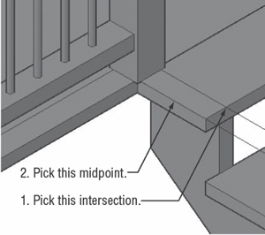
Using the endpoints of the steps as a reference, copy the posts to the other steps and then copy the handrail and posts to the opposite side of the steps.
When you are finished, the completed steps should look like Figure 16.63.
- Save your drawing as I16-16-Handrails.dwg (M16-16-Handrails.dwg).
Adding the Skirt
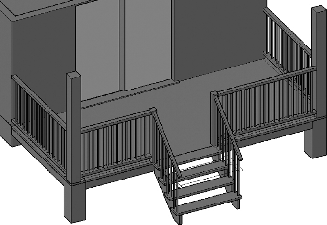
The final piece to add to the deck is a skirt, a linear member that acts as a connection surface for the structure and a visual shield so that the residents can't see under the deck. With the modeling skills and experience that you picked up in the previous chapter, this should be a quick fix; you'll just build a skirt around the three open sides of the decks to obscure the underside. Here's how:
- Continue using I16-16-Handrails.dwg (M16-16-Handrails.dwg), or open it if it's not already open.
- Switch to the Wireframe visual style, and make sure that the Endpoint running osnap is active.
Make the A-DECK-3DOB layer current.
FIGURE 16.63 The completed steps
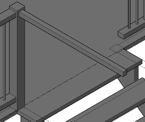
Draw a 2″×6″ (51 mm×153 mm) box on the side and front of the deck, just below the surface, as shown in Figure 16.64.
FIGURE 16.64 The 2″×6″ skirt added below the deck
Use your preferred visual style to draw the boxes. For clarity, Figure 16.65 uses the Conceptual visual style. The boxes should span the distance from the foundation to the support post and between the support posts, respectively.
- Copy the shorter box to the opposite side of the deck.
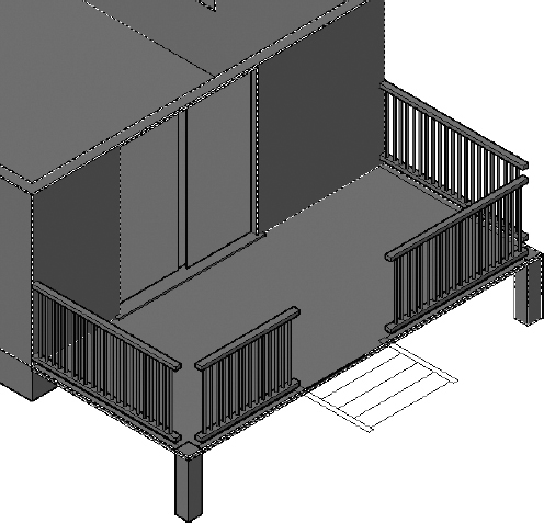
Change the visual style back to Conceptual, and your completed deck should look like Figure 16.65.
FIGURE 16.65 The completed front deck
- Save your drawing as I16-17-DeckSkirt.dwg (M16-17-DeckSkirt.dwg).
Mirroring the Front Deck
Because the front deck is similar to the back deck, you can mirror all the objects that you've already worked hard to create, to the back of the cabin, similar to the way you did in the 2D section of the book. After the objects are in place, you can edit them to meet the design criteria. Follow these steps to mirror the deck:
- Continue using I16-17-DeckSkirt.dwg (M16-17-DeckSkirt.dwg), or open it if it's not already open.
- Freeze all the layers except A-DECK-3DOB and A-DECK-STRS-3DOB. Then thaw the A-WALL layer.
- Click the face labeled TOP in the ViewCube to switch to a plan view of the cabin.
 In the Layer Properties Manager, click the open lock icon in the Lock column next to A-WALL so that objects on the A-WALL layer can't be selected or modified.
- Select all the deck and step objects.
 Click the Mirror tool in the expanded Modify panel on the Home tab.
- For the first point of the mirror line, select the midpoint of the long outside wall on the north side of the cabin, the wall that has the closet attached to the inside of it.
- For the second point, pick a point directly to the right.
- Press to accept the default option not to delete the original objects (see Figure 16.66).
FIGURE 16.66 Mirroring the front deck
TIP If the length of the cabin is displayed vertically, rather than horizontally, click the counterclockwise-facing arrow ([]) in the top-right corner of the ViewCube. This will rotate your current view 90° around the z-axis, giving your plan a more familiar orientation. - Thaw and lock the A-DECK layer. Then zoom in to the back deck.
- Change to the Wireframe visual style.
- Delete any of the handrail posts that exist between the 8″ (204 mm) 3D support posts and the 8″ (204 mm) 2D support posts on both sides of the deck (see Figure 16.67).
FIGURE 16.67 Delete the posts shown.
 Click the Move tool from the Home tab Modify panel, and drag a crossing window—dragging from right to left around the front of the deck and the stairs, as shown in Figure 16.68.
FIGURE 16.68 Moving the deck to make it narrower
- Move the deck 4′-0″ (1220 mm) in the X direction to fit the narrower rear deck's size. The floor, railings, and skirt project into the cabin, and they will be corrected in the coming steps.
- Select the deck floor, horizontal railing, and horizontal skirts. Then, using the triangular grips, move their right ends 4′ (1220 mm) to the left so that they extend only to the back wall of the cabin.
Figure 16.69 shows the back of the cabin after adjusting the features.
FIGURE 16.69 The rear deck after adjusting the handrails, skirts, and deck floor
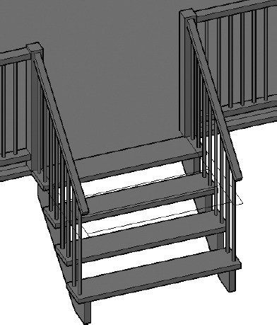
- Delete the ¾″ (20 mm) handrail posts in the vertical row on the north side of the 3D steps between the 4″ (102 mm) 3D vertical post and the 4″ (102 mm) 2D vertical post (see Figure 16.70).
 So that you don't accidentally move the deck surface, select the deck and then click the lightbulb in the lower-right corner of the Application window to choose Hide Objects from the menu that opens.
The lightbulb changes from yellow to red. This indicates that an object isolation is active.
- Using the MOVE command, move the steps into place, as shown in Figure 16.70.
- Add any new posts that are required on the south side of the steps.
- Use the triangular grips to adjust the lengths of the railings as required.
- Click the red lightbulb in the lower-right corner of the Application window, and choose End Object Isolation.
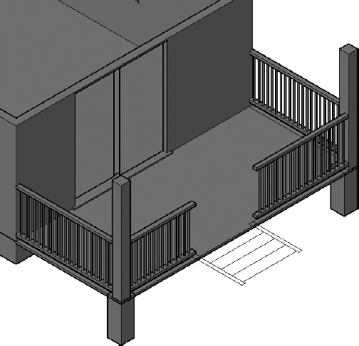
- Change to the Conceptual visual style, and drag the ViewCube to get a good look at the new deck. It should look like Figure 16.71.
- Save your drawing as I16-18-BackDeck.dwg (M16-18-BackDeck.dwg).
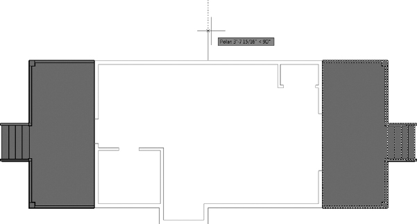
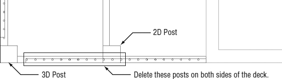
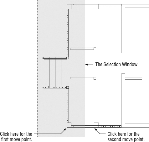
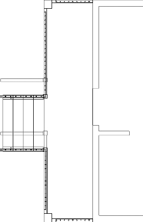
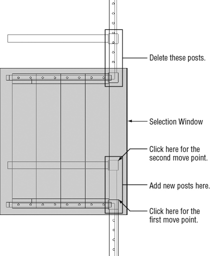
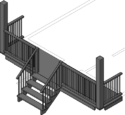
FIGURE 16.71 The completed back deck
Putting a Roof on the Cabin
You'll finish the 3D model of the cabin by constructing a roof. The surface of the roof will be a different color from the roof structure, so you'll make them as two separate objects, each on its own layer. Both objects will be extruded from the east elevation, and you'll use the Subtract Boolean function to cut the roof in the areas where it doesn't project as far as it does over the pop-out. Follow these steps:
- Continue using I16-18-BackDeck.dwg (M16-18-BackDeck.dwg), or open it if it's not already open.
- Create two new layers: A-ROOF-3DOB with color 32 and A-ROOF-DECK-3DOB with color 114. Make A-ROOF-3DOB current.
- Thaw the A-WALL-EXTR-3DOB and A-ROOF layers.
- Also thaw all layers beginning with A-ELEV except for those with a -PATT or -BNDY suffix.
- Click the TOP face of the ViewCube to change the view orientation of your drawing, and then zoom in to your east elevation (see Figure 16.72).
FIGURE 16.72 The east elevation
The east elevation is the one that displays the sliding glass door; it is found in the upper-right portion of the drawing file provided in this chapter's download.
- Use the Endpoint osnap, and carefully draw a closed polyline around the thin roof surface.
Make sure that the pline follows both the inner and outer surfaces of the roof covering and extends to the limits of the pop-out. There should be a total of six picks and then the Close option.
- Make the A-ROOF-DECK-3DOB layer current, and then draw a closed polyline around the perimeter of the roof deck in the east elevation.
 Pick the southeastern corner of the ViewCube to change to an isometric view of your drawing. Zoom back in to the east elevation.
The two roof polylines you just created by using the east elevation as a template are still in the 2D drawing plane. You'll use the 3DALIGN command to orient these polylines with the 3D model of your cabin.
- Choose the 3D Align tool from the Modify panel of the Home tab.
- At the Select objects: prompt, choose the two polylines you drew in steps 4 and 7.
The 3DALIGN command will change the orientation of the selected objects from one plane to another. To do this, you must select the axis defining the source plane and, finally, the destination plane.
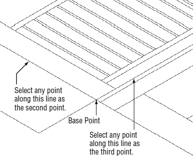
To define the source plane, you'll need to select three points: the base point, a second point, and a third point.
- Select these points, as shown in Figure 16.73.
FIGURE 16.73 Defining the source plane from the east elevation
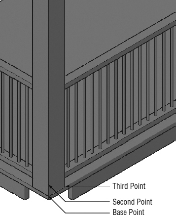
- Without exiting the 3DALIGN command, zoom in to the left deck column on the east side of your cabin, as shown in Figure 16.74.
- To define the destination plane, select the base, second, and third points, as shown in Figure 16.74.
- Zoom out so that the entire eastern side of your cabin is viewable.
Your model should look like Figure 16.75.
- Use the Extrude tool to extrude the two polylines that you just drew 43′ (13,110 mm).
- Move the extruded roof 1′-6″ (457 mm) along the positive x-axis.
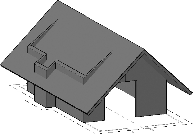
When finished, your cabin should resemble the one shown in Figure 16.76.
FIGURE 16.74 Defining the destination plane within the 3D model
FIGURE 16.75 Eastern edge of the 3D model after aligning the roof polylines to the model
- The Extrude tool creates the extrusion in the current layer, so select the thinner of the two extrusions and move it to the A-ROOF-SURF-3DOB layer by using the Properties palette.
- Save your drawing as I16-19-CabinRoof.dwg (M16-19-CabinRoof.dwg).
FIGURE 16.76 The eastern side of the cabin with extruded roof polylines correctly aligned
Adjusting the Cabin Walls
The cabin walls were drawn with a constant height. In this section, you'll create the peaks at the front and back of the cabin to accommodate the roof. To accomplish this, you will add segmentation to the top of the walls by using the Slice tool and then move the new edges in the z-axis. Here's how:
- Continue using I16-19-CabinRoof.dwg (M16-19-CabinRoof.dwg), or open it if it's not already open.
- Freeze the A-DECK-3DOB, A-DECK-STRS-3DOB, A-ROOF-3DOB, and A-ROOF-DECK-3DOB layers.
 Click the Slice button on the Solid Editing panel of the Home tab to start the SLICE command.
- At the Select objects to slice: prompt, pick the exterior walls.
The Slice tool uses a plane with an infinite depth to cut the selected objects, so you need two points to define the plane.
- At the Specify start point of slicing plane or: prompt, use the Midpoint osnap to pick the midpoint of the top of the front wall, as shown in the left image of Figure 16.77.
FIGURE 16.77 Selecting the first Slice point (left) and selecting the second Slice point (right)
- At the Specify second point on plane: prompt, pick the midpoint of the top of the back wall, as shown in the right image of Figure 16.77.
The Slice tool can display both sides of the sliced object or it can delete one of the sides. In this case, you want to keep both sides.
- At the Specify a point on desired side or [keep Both sides]: prompt, press or enter B to retain both sides.
The new edges appear on the walls (see Figure 16.78), and there are now two sets of exterior walls: one on the south side of the cabin and one on the north. Notice that the slice is centered on the wall, but not centered over the doorway.
Just as you were able to edit the size of a box object by dragging its grips, you can do the same with nonprimitive objects. The grips are available at the edges, faces, and vertices—the points where two or more edges end. You access the subobjects by holding down the Ctrl key and clicking the grip location. The grips won't appear until you click.
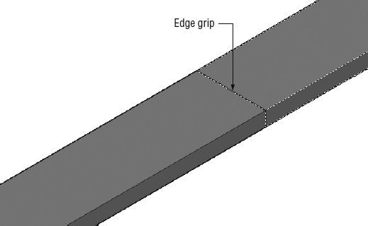
- Zoom in to the newly sliced area on the front wall. Hold the Ctrl key down, and click the middle of the top edge.
The small, rectangular, red edge grip appears as shown in Figure 16.79.
- Click the grip, and enter @0,0,8′2-1/4 (@0,0,2496) to move the edge 8′-2¼″ (2496 mm) along the z-axis.
The faces bound by the edge are adjusted accordingly and form one-half of the peak, as shown in Figure 16.80.
FIGURE 16.78 The new edges created with the Slice tool
FIGURE 16.79 Exposing the edge grip
- Adjust the edge on the other side of the front wall in the same manner.
- Zoom out, and you'll see that adjusting one end of the sliced object adjusted the other and that the peak is already constructed at the back of the cabin (see Figure 16.81).
FIGURE 16.80 Creating half of the peak
FIGURE 16.81 Both peaks are completed.
- Thaw all of the A-ROOF layers: A-ROOF, A-ROOF-3DOB, and A-ROOF-DECK-3DOB.
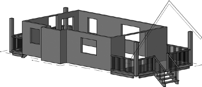
Using the ViewCube to look around the model, you can see that the northern walls and roof are largely OK. However, your walls are protruding out of the roof, along the southern edge of your cabin (see Figure 16.82).
FIGURE 16.82 The cabin model with the roof and extended walls displayed
- Save your drawing as I16-20-WallPeaks.dwg (M16-20-WallPeaks.dwg).
Tweaking the Roof and Walls
As you can see, the walls poke through the roof on the south side of the cabin, and you still need to modify the roof so that it projects out only over the pop-out. You'll do these tasks by using the subobject grips and Boolean tools.
- Continue using I16-20-WallPeaks.dwg (M16-20-WallPeaks.dwg), or open it if it's not already open.
- Use the ViewCube to rotate the view so that you can see the roof that covers the pop-out.
- Make sure Dynamic UCS is turned on and Endpoint osnaps are running.
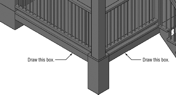
- Start the BOX command.
- Create a box, starting at the southeast corner of the roof, with a footprint that is 3′-4″ wide and that extends to a point 1′-6″ (457 mm) from the pop-out.
- Give the box some height, and then repeat the process on the opposite side of the pop-out, as shown in Figure 16.83.
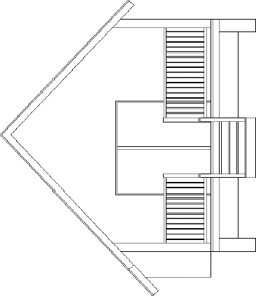
FIGURE 16.83 The boxes to be used to subtract the roof
The Dynamic UCS tool creates the boxes aligned to the roof.
- Use the grips to extend the outside edges of the boxes beyond the edges of the roof (see Figure 16.84).
- Move the boxes so that they protrude through the roof, using the endpoint of one edge as the first point of displacement and the midpoint of the same edge as the second.
When you're finished, the model should look similar to the one shown in Figure 16.85.
FIGURE 16.84 Extend the outside edges of the boxes.
FIGURE 16.85 Move the boxes so that they protrude through the roof.
- If you subtract both roof objects at the same time, the resultant roof object will be a single entity. Use this procedure to cut the boxes out of the roof:
- Copy the boxes in-place by using the same point as the base point and the displacement. This can be done by pressing at the Specify base point: and Specify displacement: prompts.
- Select the roof surface, and subtract one set of boxes from it.
- Select the roof deck, and subtract the second set of boxes from it. When you are finished, the roof should look like Figure 16.86.
FIGURE 16.86 The roof after subtracting the boxes
- Copy the boxes in-place by using the same point as the base point and the displacement. This can be done by pressing
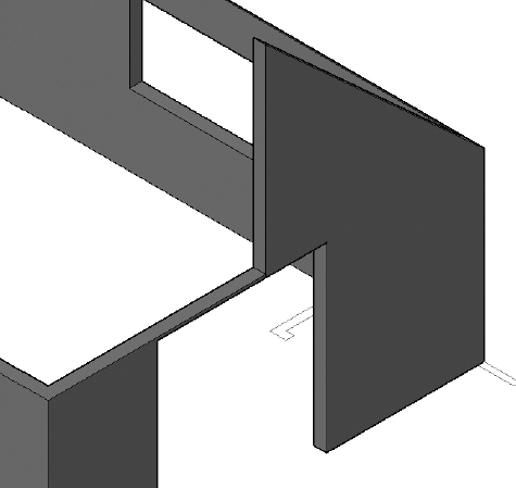
- Hold the Ctrl key down, and click the middle of the outer wall of the pop-out.
You may have trouble selecting the proper edge when both of the adjacent faces are visible. If you encounter a problem, try selecting the edge from a northeastern viewpoint.
- Turn on Ortho mode. Then move the edge downward, below the surface of the roof.
Figure 16.87 shows the edge being moved from a northeastern viewpoint.
- Freeze and unlock all the 2D layers (including those with an A-ELEV prefix), and thaw the 3D layers (with a -3DOB suffix).
- Drag the ViewCube to change to an isometric view, and then adjust the height of the roof support posts so that they extend into the roof deck but not through the roof surface (see Figure 16.88).
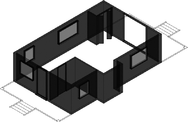
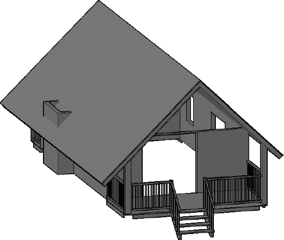
Your completed cabin should look like Figure 16.89.
- Save your file as I16-21-RoofWallFinishing.dwg (116-21-RoofWallFinishing.dwg).
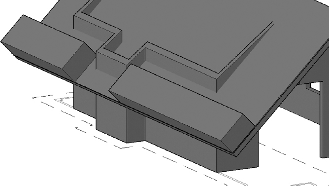
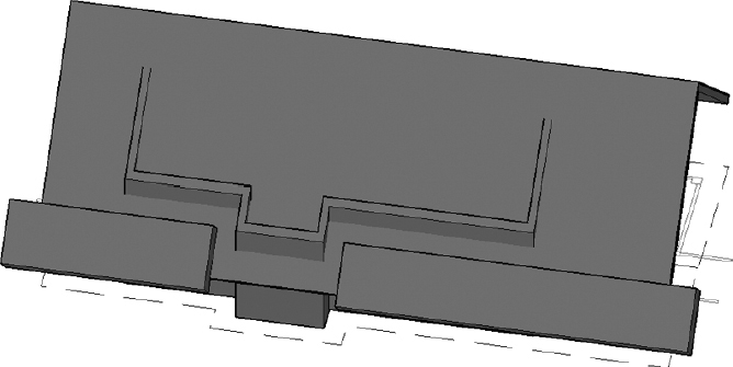
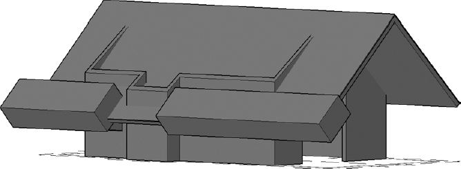
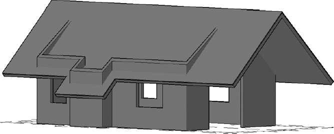
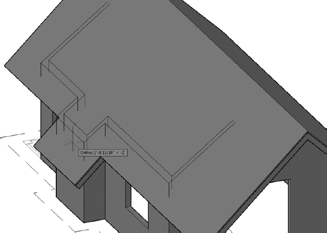
FIGURE 16.87 Adjusting the pop-out walls
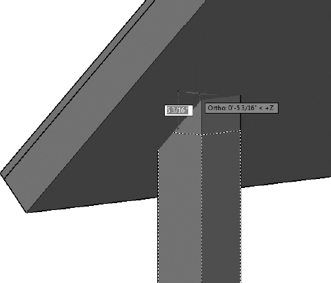
FIGURE 16.88 Adjusting the height of the roof support posts
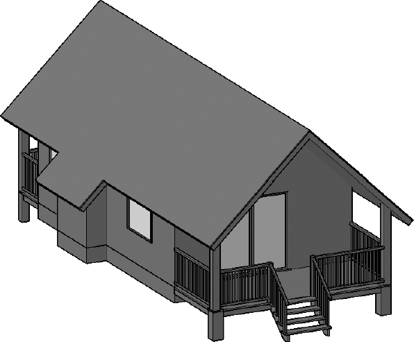
FIGURE 16.89 The completed cabin
Getting Further Directions in 3D
Covering 3D in real depth is beyond the scope of this book, but I can mention a few other tools and features that you might enjoy investigating. Here I'll summarize a few of the solid- and surface-modeling tools that I didn't cover in the tutorial on the cabin. In the next chapter, you'll look at the rendering process as it's approached in AutoCAD.
Using Other Solid-Modeling Tools
You used the box primitive to build the block-outs for the cabin walls, and the cylinder primitive for the railing posts. There are several other primitive shapes, and all of them are found on the fly-out menu on the left edge of the Modeling panel. Six of them are shown and described here. You can also see a description of the creation procedure, as shown in Figure 16.90, by pausing the cursor over any primitive option.
Cone You specify the center point of the base, the radius of the base, and the height of the pointed tip. The base is parallel to the xy-plane, and the height is perpendicular to it. You can choose for the cone to be elliptical and for the top to be flat instead of pointed.
Sphere You specify the center point and the radius or diameter.
pyramid The pyramid primitive is similar to the cone primitive, but it can have up to 32 flat sides, rather than a curved side.
Wedge The wedge has a rectangular base and a lid that slopes up from one edge of the base. You specify the base as you do with the box primitive and then enter the height.
Torus This is a donut shape. You specify a center point for the hole—the radius of the circular path that the donut makes, and the radius of the tube that follows the circular path around the center point.
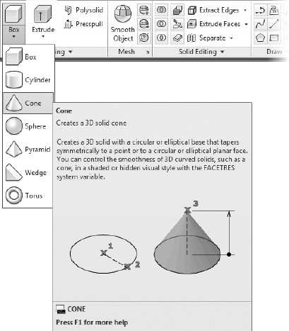
FIGURE 16.90 The other 3D primitives and the extended tooltip for the cone
The other tools on the Modeling panel are for creating additional 3D solids, manipulating existing 3D shapes, or using 2D shapes as components for making 3D shapes. You've already used some of these tools, and I'll cover the others here:
![]() Planar Surface Found exclusively on the Surface tab
Planar Surface Found exclusively on the Surface tab ![]() Create panel, the Planar Surface tool creates a flat, rectangular surface that is segmented in both directions. The segments are visible only when the object is selected or in a Wireframe visual style (see Figure 16.91).
Create panel, the Planar Surface tool creates a flat, rectangular surface that is segmented in both directions. The segments are visible only when the object is selected or in a Wireframe visual style (see Figure 16.91).
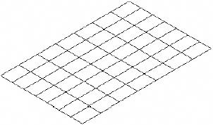
FIGURE 16.91 A Planar surface
 Revolve Select a closed 2D shape, and then define the axis and the angle of rotation. A Revolve object is shown on the left in Figure 16.92.
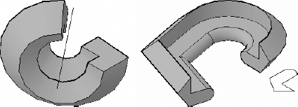
FIGURE 16.92 A Revolve object (left) and a Sweep object (right)
 Sweep Similar to the Extrude tool, the Sweep tool extrudes a 2D shape along a path to create a 3D shape. A Sweep object is shown on the right in Figure 16.92.
 Loft Similar to the Extrude and Sweep tools, the Loft tool extrudes a 2D shape along a path, but it allows you to change cross sections along the path.
![]() Press/Pull The Press/Pull tool creates a 3D object by extruding the perimeter of an area surrounded by a closed boundary. The left image in Figure 16.93 shows the closed area, and the right image shows the resultant object. The boundary does not have to be a polyline; it can simply be a conglomeration of any objects that combine to define an open area.
Press/Pull The Press/Pull tool creates a 3D object by extruding the perimeter of an area surrounded by a closed boundary. The left image in Figure 16.93 shows the closed area, and the right image shows the resultant object. The boundary does not have to be a polyline; it can simply be a conglomeration of any objects that combine to define an open area.
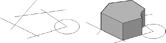
FIGURE 16.93 An enclosed area (left) and the result of using the Press/Pull tool (right)
![]() Helix Located on the Home tab
Helix Located on the Home tab ![]() Draw panel, a Helix object is a 2D or 3D spiral (see Figure 16.94). When you use it in conjunction with the Sweep tool, you can create springs, corkscrews, coils, and so forth.
Draw panel, a Helix object is a 2D or 3D spiral (see Figure 16.94). When you use it in conjunction with the Sweep tool, you can create springs, corkscrews, coils, and so forth.
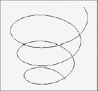
FIGURE 16.94 A helix extending in the Z direction
There are two other Boolean tools for modifying solids. When you formed the cabin walls, you used the Subtract tool as well as Slice. Two other solids-editing tools, Union and Intersect, create an object based on two overlapping objects:
Union Joins the two objects and eliminates any internal edges
Intersect Finds the volume that two solids have in common and retains that volume while deleting the other portions of the objects
This is only a brief introduction to the tools used for creating and modifying solids, but it should be enough to get you started.
Using Mesh-Modeling Tools
In addition to the solid objects available in AutoCAD, a set of tools is available to create mesh models. Unlike solids, meshes can't be easily manipulated and do not have a true volume, just faces that surround an empty area. For example, imagine this book next to a cellophane wrapper having the same dimensions. The book would be a solid, and the wrapper would be a mesh.
The following a few of the mesh tools found on the Mesh Ribbon tab (see Figure 16.95).
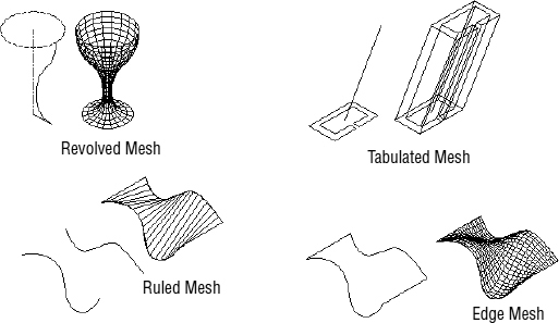
FIGURE 16.95 AutoCAD's mesh-modeling tools
Revolved Mesh Creates a 3D surface mesh by rotating a 2D curved line around an axis of revolution.
Tabulated Mesh Creates a 3D surface mesh by extruding a 2D object in a direction determined by the endpoints of a line, an arc, or a polyline.
Ruled Mesh Creates a 3D surface mesh between two selected shapes.
Edge Mesh Creates a 3D surface mesh among four lines that are connected at their endpoints. Each line can be in 2D or 3D, and the original shape must be a boundary of a shape that doesn't cross or conflict with itself.
Most 3D models today utilize the solid-modeling tools for their basic shapes because the tools for adding, subtracting, slicing, and so forth are easy to use and allow complex shapes to be fabricated quickly. Still, mesh-modeling, legacy tools retained from AutoCAD's initial foray into 3D have their uses. Any serious 3D modeler will be familiar with both sets of tools.
Using Surface-Modeling Tools
The surface-modeling tools share some similarities with both the solid- and mesh-modeling tools already discussed. Surfaces are like meshes in that they do not have a true volume; the cellophane wrapper analogy also applies to surfaces. On the other hand, you'll notice that a number of tools appear on both the Solid and Surface Ribbon tabs.
Tools such as Loft, Sweep, Extrude, and Revolve are found on both tabs, and they are nearly identical in both contexts. The core difference between the two types is the 3D object created. When these tools are used from the Solid tab, they create solid objects, with volume and mass. Using these same tools from the Surface tab will create a skeleton object, a cellophane wrapper, with neither volume nor mass.
Figure 16.96 shows two boxes, each created using the Extrude tool. The box on the left was created using the Extrude tool found on the Solid tab, and it is a solid box with a top, bottom, and sides. By comparison, the box on the right was created using the Extrude tool found on the Surface tab. Notice how it lacks both a top and a bottom, but each of its four sides is constructed with smaller rectangles. This grid structure is more easily manipulated into complex shapes, something that's much harder to do using solid objects.
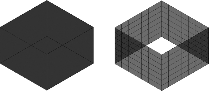
FIGURE 16.96 Rectangles extruded with the Extrude tool on the Solid tab (left) and the Extrude tool on the Surface tab (right)
Surfaces can be created by using any of the tools shown in Figure 16.97.
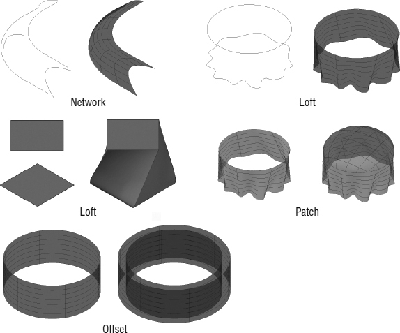
FIGURE 16.97 AutoCAD's surface-modeling tools
![]() Network Creates a 3D surface between several curves, other 3D surfaces, or solids in the U and V directions
Network Creates a 3D surface between several curves, other 3D surfaces, or solids in the U and V directions
![]() Loft Creates a 3D surface between several 2D cross sections
Loft Creates a 3D surface between several 2D cross sections
![]() Sweep Creates a 3D surface along a path, similar to the Solid Sweep tool shown earlier in Figure 16.92
Sweep Creates a 3D surface along a path, similar to the Solid Sweep tool shown earlier in Figure 16.92
![]() Planar Creates a flat surface between several coplanar objects
Planar Creates a flat surface between several coplanar objects
![]() Extrude Creates a 3D surface from a 2D or 3D line, curve, or polyline
Extrude Creates a 3D surface from a 2D or 3D line, curve, or polyline
![]() Revolve Creates a 3D surface by rotating a 2D line or curve around an axis
Revolve Creates a 3D surface by rotating a 2D line or curve around an axis
![]() Blend Creates a continuous 3D surface between two existing surfaces
Blend Creates a continuous 3D surface between two existing surfaces
![]() Patch Creates a 3D surface to close or cap an existing 3D surface
Patch Creates a 3D surface to close or cap an existing 3D surface
![]() Offset Creates a 3D surface parallel to an existing 3D surface
Offset Creates a 3D surface parallel to an existing 3D surface
If You Would Like More Practice…
Creating 3D models is a highly effective way to communicate designs with groups of people who may not otherwise know how to read engineering plans. For more practice modeling in 3D, you can try the following:
- Model the kitchen cabinets and appliances.
- Add a small window to the back door.
- Create mullions for each of your windows.