
CHAPTER 2
Learning Basic Commands to Get Started
Now that you've taken a quick tour of the Autodesk® AutoCAD® and Autodesk® AutoCAD LT® screens, you're ready to begin drawing! This chapter introduces you to some basic commands used in drawing with AutoCAD and AutoCAD LT. To get you started, this chapter guides you through the process of drawing a simple shape.
As you create this first drawing, you'll learn to use several essential AutoCAD commands that will serve as a foundation for the rest of this book. First you'll become familiar with the LINE command and how to draw lines at a specific length. Then we'll go over the strategy for completing the form.
In this chapter, you will learn to
- Understand coordinate systems
- Draw your first object
- Erase, offset, fillet, extend, and trim objects in a drawing
Using the Line Command
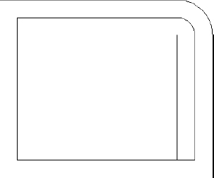
The LINE command is essential to all AutoCAD drawings. It is the first command you'll explore as you construct the shape shown in Figure 2.1. Whenever starting a brand new drawing in AutoCAD, it's always best to take a step back and consider the object or objects you would like to construct. In this case, the shape shown in Figure 2.1 most closely resembles a square. To apply this basic strategy, you'll begin by defining each of the four sides of the square by using the LINE command, and then you will build upon this basic shape with several additional commands introduced later in this chapter.
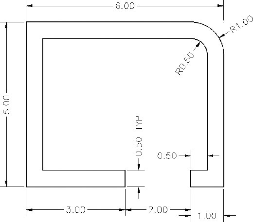
FIGURE 2.1 The shape you'll draw
In traditional architectural drafting, lines were often drawn to extend slightly past their endpoints (see Figure 2.2). Today we have entire applications that can open a CAD drawing and not only apply this effect but can also make the image appear hand-drawn. A popular application for applying such an effect is Autodesk® Impression, which is offered at no charge for those with subscriptions to most Autodesk software. We won't be covering Autodesk Impression in this book; however, you can visit http://autodesk.com/impression to learn more about it.
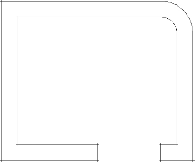
FIGURE 2.2 The shape drawn with overlapping lines
The LINE command draws a straight line segment between locations on existing objects, geometric features, or two points that you can choose anywhere within the drawing area. You can designate these points by left-clicking them on the screen, by entering the x- and y-coordinates for each point, or by entering distances and angles from an existing point. After you draw the first segment of a line, you can end the command or draw another line segment beginning from the end of the previous one. You can continue to draw adjoining line segments for as long as you like. Let's see how this works.
To be sure that you start with your drawing area configured the way it's set up for this book, expand the Application menu (the red A button in the top-left corner of the AutoCAD user interface), and choose Close ![]() All Drawings to close any open drawings. The Application menu is shown in Figure 2.3.
All Drawings to close any open drawings. The Application menu is shown in Figure 2.3.
![]()
Like many other Windows-based programs, AutoCAD provides many ways you can close drawings individually as well. The first and perhaps most popular way is to click the icon in the upper-right corner of any drawing next to the Minimize and Restore icons. The Quick View Drawings feature found on the AutoCAD status bar also features a similar icon from which drawings may be closed individually. Drawings can also be closed from the Application menu by choosing Close ![]() Current Drawing. Finally, if you're an aspiring keyboard warrior, press Ctrl+F4 (be sure to press both keys at the same time) to close the current drawing.
Current Drawing. Finally, if you're an aspiring keyboard warrior, press Ctrl+F4 (be sure to press both keys at the same time) to close the current drawing.
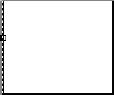
As shown in Figure 2.4, after you no longer have any drawings open, your drawing area becomes a gradient gray, blank screen with no crosshairs cursor. The Ribbon disappears, and only three buttons remain in the Quick Access toolbar area on the left side of the title bar (along with the three informational buttons in the Quick Access toolbar).
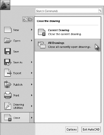
FIGURE 2.3 Use the Application menu to close any open drawings.
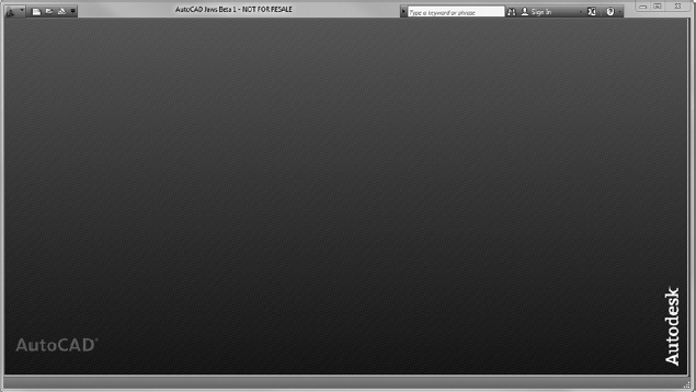
FIGURE 2.4 The AutoCAD user interface without any drawings open
Now follow these steps to begin using the LINE command:
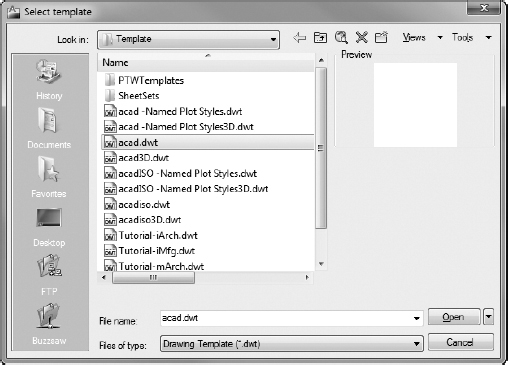
 Click the New button at the left end of the Quick Access toolbar. In the Select Template dialog box, select the acad.dwt file (acadlt.dwt for AutoCAD LT users) if it's not already selected, and click Open, as shown in Figure 2.5. The Ribbon, crosshair cursor, and toolbars return, and you now have a blank drawing in the drawing area.
FIGURE 2.5 Choose the acad.dwt template in the Select Template dialog box.
 NOTE: DWT files are drawing templates with several parameters, such as dimension styles, layers, plotting settings, and more already set.
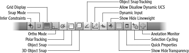
- On the left side, some of the tools, such as Object Snap and Dynamic Input, are turned on while others remain off. Make sure that Polar Tracking, Object Snap, Object Snap Tracking, Allow/Disallow Dynamic UCS, Dynamic Input, and Selection Cycling are turned on and all the others are turned off. You can identify the buttons by pausing over each and exposing its tooltip. Your toolbar should look similar to Figure 2.6.
 From the Ribbon, choose the Home tab
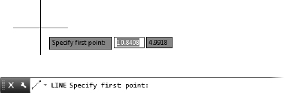
  Draw panel, and then click the Line tool. Look at both the bottom of the command-line interface and your cursor. Because Dynamic Input is turned on, prompts such as this one display both at the command line and next to the cursor (see Figure 2.7).
FIGURE 2.7 Both the command prompt and the cursor change to reflect the current command.
 TIP: You can also start the LINE command by typing LINE or L and pressing the Enter key, spacebar, or the right mouse button.
The prompt now tells you that the LINE command is started (Command: _line) and that AutoCAD is waiting for you to designate the first point of the line (Specify first point:).
 Move the cursor onto the drawing area, and note that the small box at the intersection of the crosshairs is not there.
When the cursor is used to select objects (the default condition), a small square displays atop the cursor. This small square cursor is known as the pickbox and indicates when AutoCAD expects you to select an existing object in lieu of a point. When the cursor is used to designate a point in commands such as the current LINE command, the pickbox is not visible. Using the left mouse button, click a random point in the drawing area to start a line.
- Move the cursor away from the point you clicked, and notice how a line segment appears that stretches like a rubber band from the point you just picked to the cursor. The line changes length and direction as you move the cursor, and these values are shown as input boxes in the drawing area.
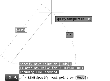
- Look at the command line again, and notice that the prompt has changed (see Figure 2.8).
FIGURE 2.8 The command prompt changes for the next point, and the line's length and direction are shown in the drawing area.
The prompt is now telling you that AutoCAD is waiting for you to designate the next point ( Specify next point or [Undo]:).
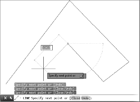
- Continue picking points and adding lines as you move the cursor around the screen (see Figure 2.9).
After you draw the second segment, the command window repeats the Specify next point or [Close/Undo]: prompt each time you pick another point. The Dynamic Input fields and command prompt appear near the cursor, showing the angle and distance from the last point selected.
- When you've drawn six or seven line segments, press Enter (
 ) to end the LINE command. The cursor separates from the last drawn line segment.
The Type a command has returned to the bottom line. This tells you that no command is currently running.
![]() TIP: The Enter (
TIP: The Enter (![]() ) key exits the LINE command and several others. Another option to exit the LINE command is to right-click and choose Enter from the context menu. This may require an extra step, but it may still be faster because your eyes never leave the screen. When you're not entering data, the spacebar also acts like the Enter (
) key exits the LINE command and several others. Another option to exit the LINE command is to right-click and choose Enter from the context menu. This may require an extra step, but it may still be faster because your eyes never leave the screen. When you're not entering data, the spacebar also acts like the Enter (![]() ) key and executes a command.
) key and executes a command.
In this exercise, you used the left mouse button to click the Line tool on the Ribbon and also to pick several points in the drawing area to make line segments. You then pressed Enter (![]() ) on the keyboard to end the LINE command.
) on the keyboard to end the LINE command.
![]() NOTE: In the exercises that follow, the Enter symbol (
NOTE: In the exercises that follow, the Enter symbol (![]() ) is used. When I ask you to type or enter something, it means to type the data that follows the word type or enter and then to press the Enter key (
) is used. When I ask you to type or enter something, it means to type the data that follows the word type or enter and then to press the Enter key (![]() ). For example, rather than writing type L, and press the Enter key, I'll write type L
). For example, rather than writing type L, and press the Enter key, I'll write type L![]() . Finally, although I'll capitalize the names of AutoCAD commands, be aware that commands are not case sensitive and may be entered however you wish.
. Finally, although I'll capitalize the names of AutoCAD commands, be aware that commands are not case sensitive and may be entered however you wish.
Using Coordinates
A coordinate system consists of numbered scales that identify an initial, or base, point and the direction for measuring subsequent points on a graph. The Cartesian Coordinate System, named after the philosopher René Descartes, who defined the xy-coordinate system in the 1600s, consists of three numbered scales, called the x-axis, y-axis, and z-axis, that are perpendicular to each other and extend infinitely in each direction. As illustrated in Figure 2.10, each pair of axes (xy, xz, yz) forms a flat plane. Most of your time working with AutoCAD will be spent drawing in the xy-plane.
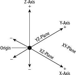
FIGURE 2.10 The x-, y-, and z-axes and the related xy-, xz-, and yz-planes
The point where the scales intersect is called the origin. For each axis, all values on one side of the origin are positive, all values on the other side are negative, and values that fall in line with the origin have a value of 0 (zero). The divisions along the scales may be any size, but each division must be equal.
The axes divide the coordinate system into four regions called quadrants. Quadrant I is the region above the x-axis and to the right of the y-axis. Quadrant II is the region above the x-axis and to the left of the y-axis. Quadrant III is the region below the x-axis and to the left of the y-axis. Quadrant IV is the region below the x-axis and to the right of the y-axis. Most of your work in AutoCAD will be done in Quadrant I, and this is the area shown when you first open a drawing.
Any point on a graph can be specified by giving its coordinates relative to the origin, indicated as a combination of the X value and the Y value delineated with a comma. For example, a coordinate of 5,7 means a point on the coordinate system that is 5 units in the positive X direction and 7 units the positive Y direction. Figure 2.11 shows a typical Cartesian Coordinate System and the default region used as the drawing area in a new AutoCAD file.
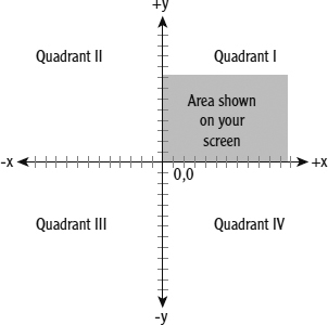
FIGURE 2.11 The x- and y-coordinates of the drawing area
![]() NOTE: AutoCAD displays a readout for the z-coordinate as well, but you can ignore it for now because you'll be working in only two dimensions for the majority of this book. The z-coordinate always reads 0 until you work in three dimensions. (This is covered in later chapters.) AutoCAD LT doesn't have the readout for the z-coordinate because it doesn't have 3D capabilities.
NOTE: AutoCAD displays a readout for the z-coordinate as well, but you can ignore it for now because you'll be working in only two dimensions for the majority of this book. The z-coordinate always reads 0 until you work in three dimensions. (This is covered in later chapters.) AutoCAD LT doesn't have the readout for the z-coordinate because it doesn't have 3D capabilities.
In this next exercise, you'll try using the LINE command again, but instead of picking points in the drawing area with the mouse as you did before, this time you'll enter the x- and y-coordinates for each point from the keyboard. To see how to do this, follow these steps:
You can also start the ERASE command by typing E![]() .
.
 Click the Erase button from the Home tab Modify Ribbon panel.
- Type ALL. The objects in the drawing become dashed to indicate that they are selected.
- Press to clear the screen.
 Click the Dynamic Input button on the status bar to turn off this feature. The button changes to a gray background.
 Click the Grid Display button on the status bar to display the Grid if it is not already turned on. The gridlines that display provide a graphical representation of the Cartesian Coordinate System used by AutoCAD.
Now begin drawing lines again by following these steps:
- Start the LINE command by clicking the Line button from the Home tab Draw panel on the Ribbon.
- Type 7,2 to start the first line segment at a location 7 units above and 2 units to the right of the drawing's origin point.
- Type 11,3 to determine the endpoint of the line. Then enter the following:
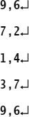
- Press again to end the command.
Figure 2.12 shows the completed drawing with coordinates and direction arrows added for clarity.
FIGURE 2.12 Completed drawing showing coordinates and direction of lines
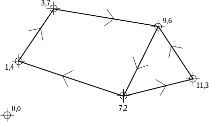
The lines are similar to those you drew previously, but this time you know where each point is located relative to the 0,0 point. In the drawing area, every point has an absolute x- and y-coordinate. In steps 2 through 4, you entered the x- and y-coordinates for each point. For a new drawing such as this one, the origin (0,0 coordinate) is in the lower-left corner of the drawing area, and all points in the drawing area have positive x- and y-coordinates.
Let's explore how the cursor is related to the coordinates in the drawing:
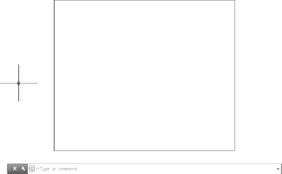
 Click the Zoom Extents button located on the navigation bar (the semitransparent vertical bar under the ViewCube), or type ZOOM E to adjust your view to show the extents of the drawing area.
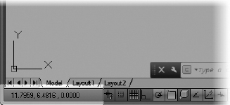
- Move the cursor around, and notice the left end of the status bar at the bottom of the screen. This is the coordinate readout, and it displays the coordinates of the cursor's position, as shown in Figure 2.13.
FIGURE 2.13 The x- and y-coordinates of the cursor are shown at the bottom of the AutoCAD window.
- Move the cursor as close to the lower-left corner of the drawing area as you can without it changing into an arrow. The coordinate readout should be close to 0.0000, 0.0000, 0.0000.
- Move the cursor to the top-left corner of the drawing area. The readout changes to something close to 0.0000, 7.0000, 0.0000, indicating that the top of the screen is 7 units from the bottom.
- Move the cursor one more time to the upper-right corner of the drawing area. The readout still has a y-coordinate of approximately 7.0000. The x-coordinate now has a value around 10.5.
The drawing area of a new drawing is preset with the lower-left corner of the drawing at the coordinates 0,0.
![]() NOTE: For the moment, it doesn't matter what measure of distance these units represent. I address that topic in Chapter 3, “Setting Up a Drawing.” Don't worry about the four decimal places in the coordinate readout; the number of places is controlled by a setting you'll learn about soon.
NOTE: For the moment, it doesn't matter what measure of distance these units represent. I address that topic in Chapter 3, “Setting Up a Drawing.” Don't worry about the four decimal places in the coordinate readout; the number of places is controlled by a setting you'll learn about soon.
Using Relative Coordinates
Once you understand the coordinate system used by AutoCAD, you can draw lines to any length and in any direction. Look at the shape shown earlier in Figure 2.1. Because you know the dimensions, you can calculate (by adding and subtracting) the absolute coordinates for each vertex—the connecting point between two line segments—and then use the LINE command to draw the shape by entering these coordinates from the keyboard. However, AutoCAD offers you several tools for drawing this box much more easily. Two of these tools are the Relative Cartesian and Relative Polar Coordinate Systems.
When you're drawing lines, these coordinate systems use a set of new points based on the last point designated rather than on the 0,0 point of the drawing area. They're called relative systems because the coordinates used are relative to the last point specified. If the first point of a line is located at the coordinate 4,6 and you want the line to extend 8 units to the right, the coordinate that is relative to the first point is 8,0 (8 units in the positive X direction and 0 units in the positive Y direction), whereas the actual—or absolute—coordinate of the second point is 12,6.
The Relative Cartesian Coordinate System uses relative x- and y-coordinates in the manner shown, and the Relative Polar Coordinate System relies on a distance and an angle relative to the last point specified. You'll probably favor one system over the other, but you need to know both systems because you'll sometimes find that, given the information you have at hand, one will work better than the other. A limitation of this nature is illustrated in Chapter 4, “Developing Drawing Strategies: Part 1.”
When the Dynamic Input tool is turned off, you'll need to prefix the coordinate with an at symbol (@). In the previous example, you would enter the relative Cartesian coordinates as @8,0. The @ lets AutoCAD know that the numbers following it represent coordinates that are relative to the last point designated. When the Dynamic Input tool is turned on, relative coordinates are assumed and the @ symbol is not required.
Relative Cartesian Coordinates
The Cartesian system of coordinates uses a horizontal (x) component and a vertical (y) component to locate a point relative to the 0,0 point. The relative Cartesian system uses the same components to locate the point relative to the last point picked, so it's a way of telling AutoCAD how far left or right, and up or down, to extend a line or to move an object from the last point picked (see Figure 2.14). If the direction is to the left, the x-coordinate will be negative. Similarly, if the direction is down, the y-coordinate will be negative. Use this system when you know the horizontal and vertical distances from point 1 to point 2. To enter data using this system, use this form: @x,y.
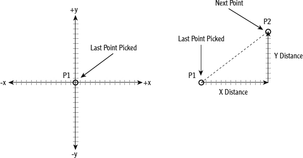
FIGURE 2.14 The Relative Cartesian Coordinate System
Relative polar Coordinates
The Relative Polar Coordinate System requires a known distance and direction from one point to the next. Calculating the distance is straightforward: it's always positive and represents the distance away from the first point that the second point will be placed. The direction requires a convention for determining an angle. AutoCAD defines right (toward three o'clock) as the default direction of the 0° angle. All other directions are determined from a counterclockwise rotation (see Figure 2.15). On your screen, up is 90°, left is 180°, down is 270°, and a full circle is 360°. To let AutoCAD know that you're entering an angle and not a relative y-coordinate, use the less-than symbol (<) before the angle and after the distance. Therefore, in the previous example, to designate a point 8 units to the right of the first point, you would enter @8<0, or simply 8<0 when the Dynamic Input tool is active.
![]() NOTE: Use the Relative Polar Coordinate System to draw a line from the first point when you know the distance and direction to its next point. Enter data using this form: @distance<angle.
NOTE: Use the Relative Polar Coordinate System to draw a line from the first point when you know the distance and direction to its next point. Enter data using this form: @distance<angle.
Using the Direct Distance Method
You can also draw lines by placing the cursor at any angle relative to the last point and entering a distance value at the command prompt. The line is drawn from the last point toward or through the cursor location at the length specified. The Direct Distance method is often used when either Ortho mode or Polar Tracking is turned on.
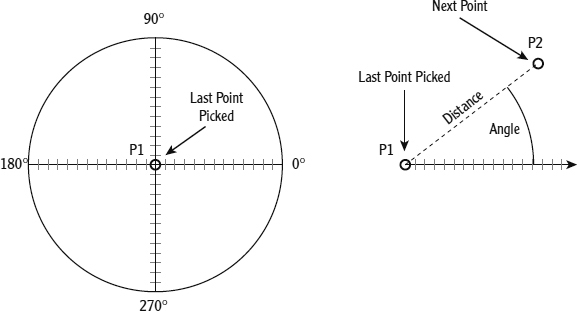
FIGURE 2.15 The Relative Polar Coordinate System
![]() NOTE: When in a drawing command, Ortho mode restricts the cursor to horizontal or vertical movements. Lines, for example, can be drawn only at 0°, 90°, 180°, and 270°. Ortho mode is toggled on by using the Ortho Mode button on the status bar or by pressing the F8 key.
NOTE: When in a drawing command, Ortho mode restricts the cursor to horizontal or vertical movements. Lines, for example, can be drawn only at 0°, 90°, 180°, and 270°. Ortho mode is toggled on by using the Ortho Mode button on the status bar or by pressing the F8 key.
Drawing the Shape
Now that you have the basics, the following exercises will take you through the steps required to draw the four lines that form the outline of the shape using both relative coordinate systems.
Using Relative Cartesian Coordinates
To begin drawing the box, use the same drawing:
- If your drawing is already blank, jump to step 2. If you still have lines on your drawing, start the ERASE command, type ALL, and then press again to delete them.
- Start the LINE command by choosing Home tab Draw panel Line.
- At the Specify first point: prompt in the command window, type 3,3. This is an absolute Cartesian coordinate, and it will be the first point.
- Type @6,0.
- Type @0,5.
- Turn on the Dynamic Input tool in the status bar and, if necessary, scroll the mouse wheel to zoom out to see the extents of the lines.
- Type −6,0. Notice that, because Dynamic Input is turned on, the @ symbol is no longer required to input relative coordinates.
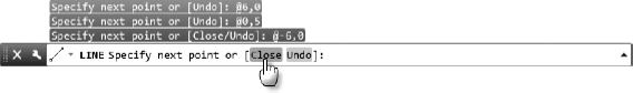
- Look at the command prompt. It reads Specify next point or [Close/Undo] :. Items enclosed in brackets are additional available options at that particular point of the command that can be entered at the command prompt. Only the capitalized letters are required to execute an option.
 Click Close from the command-line interface to execute the Close option, as shown in Figure 2.16.
FIGURE 2.16 Specifying a command option by clicking it within the command-line interface
Typing the letter C![]() after drawing two or more lines closes the shape by extending the next line segment from the last point specified to the first point (see Figure 2.17). It also ends the LINE command. Notice that, in the command-line interface, the prompt is Type a command :. This signifies that AutoCAD is ready for a new command.
after drawing two or more lines closes the shape by extending the next line segment from the last point specified to the first point (see Figure 2.17). It also ends the LINE command. Notice that, in the command-line interface, the prompt is Type a command :. This signifies that AutoCAD is ready for a new command.
Erasing Lines
To prepare to draw the box again, use the ERASE command to erase the four lines you just drew:
- Start the ERASE command by choosing Home tab Modify panel Erase tool.
FIGURE 2.17 The first four lines of the box
Notice how the cursor changes from the crosshairs to a little square. As mentioned earlier, this is called the pickbox. Its appearance indicates that AutoCAD is ready for you to select objects on the screen. Also note the command line; it's prompting you to select objects.
- Place the pickbox on one of the lines, and click that line when it highlights. The line appears dashed to indicate that it is selected.
- Repeat step 2 for the remaining lines.
- Press . The objects are erased, and the ERASE command ends.
![]() NOTE: You've been introduced to two methods of selecting lines to be erased: typing ALL
NOTE: You've been introduced to two methods of selecting lines to be erased: typing ALL![]() and using the pickbox to select them. Throughout this book, you'll learn about other ways to select objects. The selection process is important in AutoCAD because you need to be able to select objects quickly and precisely.
and using the pickbox to select them. Throughout this book, you'll learn about other ways to select objects. The selection process is important in AutoCAD because you need to be able to select objects quickly and precisely.
Controlling How the Selection Tools Are Displayed
When you move the cursor over an object, AutoCAD highlights the object. This is called rollover highlighting. It tells you that clicking while the object is highlighted selects that object. You have some choices as to how this highlighting appears:
- In the Application menu, click the Options button at the bottom (Application menu Options) to open the Options dialog box.
- Click the Selection tab.
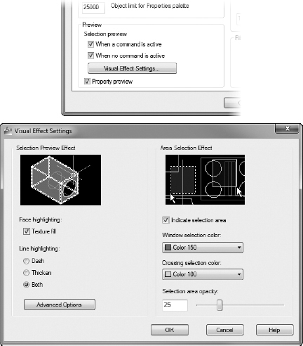
Notice the Preview group at the bottom of the left side (see Figure 2.18, top). Here you can activate or deactivate the check boxes to control whether rollover highlighting occurs when a command is running or when no command is running. If both check boxes are selected, the feature operates all the time.
- Click the Visual Effect Settings button below the check boxes to open the Visual Effect Settings dialog box (see Figure 2.18, bottom).
FIGURE 2.18 The Preview group of the Selection tab in the Options dialog box (top) and the Visual Effect Settings dialog box (bottom)
There are two groups: Selection Preview Effect and Area Selection Effect. The Selection Preview Effect group controls how the rollover-highlighting feature is displayed. Lines can dash, lines can thicken, and lines can both dash and thicken, depending on which radio button is selected.
- Make any changes you want and then click OK. Back in the Options dialog box, click OK to return to your drawing.
Feel free to experiment with these settings until you find a combination that works for you.
Using Relative Polar Coordinates
Now draw the shape again using the Relative Polar method by following these steps:
- Start the LINE command by choosing Home tab Draw panel Line tool.
- Type 3,3 to start the box at the same point.
- Type 6<0. Because the Dynamic Input tool is turned on, the @ symbol is not required.
- Type 5<90.
- Type 6<180.
- Type C to close the box and end the LINE command. Your box once again resembles the box shown earlier in Figure 2.17.
You can see from this exercise that you can use either method to draw a simple shape. When the shapes you're drawing become more complex and the amount of available information about the shapes varies from segment to segment, one of the two relative coordinate systems will turn out to be more appropriate. As you start drawing the floor plan of the cabin in Chapters 3 and 4, you'll get more practice using these systems.
Using Direct Input
Now draw the box once more—this time using the Direct Input method by following these steps:
- Erase the lines in your drawing as you did in a prior exercise (Home tab Modify panel Erase tool).
 Make sure Polar Tracking is turned on and then start the LINE command.
- Type 3,3 to start the box at the same point.
- Place the cursor so that it is directly to the right of the first point.
When the cursor is nearly perpendicular, it will snap to a perfectly horizontal orientation. The Dynamic Input field shows a value of 0° and the distance from the first point, as shown in Figure 2.19.
FIGURE 2.19 Drawing a line by using the Direct Input method
- Type 6. The first line is created, extending from the initial point to a point 6 units away at an angle of 0°. Notice that the @ symbol is not required when using direct input.
- Move the cursor so that it is directly above the last point until the angle field reads 90°; then type 5. A vertical line 5 units long is drawn from the previous point.
- Move the cursor so that it is directly to the left of the end of the last line drawn, and then type 6.
A horizontal line 6 units long is drawn from the previous point. Even though the line is drawn in the negative X direction, the minus sign (negative indicator) is not required. Because Dynamic Input was turned on, the minus sign was implied based on the location of your cursor. In other words, AutoCAD drew the line in the direction your cursor was located.
- Type c to close the box and end the LINE command. Your box once again resembles the box shown in Figure 2.17 earlier.
You can see from these exercises that you can use multiple methods to draw a simple shape. Showing so many methods may seem a little redundant at this point; however, as the shapes you draw become more complex and the amount of available information about the shapes varies from segment to segment, you'll likely begin choosing one method or another based on the information available to you. As you start drawing the floor plan of the cabin in Chapters 3 and 4, you'll get more practice applying these methods to more realistic scenarios, and you'll probably begin establishing the methods that work best for you.
Some additional tools make the process of drawing simple, orthogonal lines like these much easier. I introduce these tools in the following three chapters.
Using the Offset Command
The next task is to create the lines that represent the inside walls of the box. Because they're all equidistant from the lines you've already drawn, the OFFSET command is the appropriate command to use. You'll offset the existing lines 0.5 units to the inside.
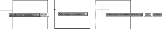
The OFFSET command involves three steps:
- Setting the offset distance (Specify offset distance)
- Selecting the object to offset (Select object to offset)
- Indicating the offset direction (Specify point on side to offset)
Here's how it works:
 Be sure the prompt line in the command interface reads Type a command. If it doesn't, press the Esc key until it does. Then launch the OFFSET command by choosing the Home tab Modify panel Offset tool.
You can also start the OFFSET command by typing O
 .
.The prompt changes to Specify offset distance or [Through/Erase/Layer] <Through>:. This is a confusing prompt, but it will become clear soon. For now, let's specify an offset distance through the keyboard.
 TIP: As important as it is to keep an eye on the command line, some prompts may not make sense to you until you get used to them. When using the Dynamic Input option, notice that the command prompt also appears at the cursor.
- Type 0.5 for a distance to offset the lines a half-unit.
Now you move to the second stage of the command. Note that the cursor changes to a pickbox, and the prompt changes to Select object to offset or [Exit/Undo] <Exit>:.
- Place the pickbox on one of the lines, and click the line when it highlights.
The selected line appears dashed to indicate that it is selected (see Figure 2.20), the cursor changes back to the crosshairs, and the prompt changes to Specify point on side to offset or [Exit/Multiple/Undo] <Exit>:.
FIGURE 2.20: From left to right, the series of prompts required to execute the OFFSET command: distance, object, and direction
AutoCAD is telling you that, to determine the direction of the offset, you must specify a point on one side of the line or the other. You make the choice by selecting anywhere in the drawing area on the side of the line where you want the offset to occur.
- Click a point somewhere inside the box. (You don't have to be precise, just so long as you select a point inside the box.)
The offset takes place, and the new line is exactly 0.5 units to the inside of the chosen line (see Figure 2.21). Notice that the pickbox comes back on. The OFFSET command is still running, and you can offset more lines by the same distance.
FIGURE 2.21 The first line is offset.
You have three more lines to offset.
- Click another line; then click inside the box again. The second line is offset.
- Click a third line, click inside the box, click the fourth line, and then click again inside the box (see Figure 2.22).
- Press to end the OFFSET command.
![]() NOTE: The offset distance stays set at the last distance you specify—0.5, in this case—until you change it.
NOTE: The offset distance stays set at the last distance you specify—0.5, in this case—until you change it.
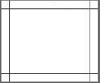
FIGURE 2.22 Four lines have been offset.
This command is similar to the LINE command in that it keeps running until it's stopped. With OFFSET, after the first offset, the prompts switch between Select object to offset or [Exit/Undo] <Exit>: and Specify point on side to offset or [Exit/Multiple/Undo] <Exit>: until you press ![]() or the spacebar to end the command.
or the spacebar to end the command.
You can cancel a command at any time by pressing Esc or by right-clicking and choosing Cancel from the context menu.
SPECIFYING DISTANCES FOR THE OFFSET COMMAND
The prompt you see in the command-line interface after starting the OFFSET command is as follows:
Specify offset distance or [Through/Erase/
Layer] <Through>:
This prompt describes several options for setting the offset distance:
- Enter a distance from the keyboard.
- Select two points on the screen to establish the offset distance as the distance between those two points.
- Press to accept the offset distance or option that is displayed in the prompt in the angle brackets.
- Type T to use the Through option. When you select this option, you're prompted to select the line to offset. You're then prompted to pick a point. The line will be offset to that point. When you pick the next line to offset, you then pick a new point to locate the position of the new line. The Through option allows each line to be offset a different distance.
- Type E, and then type Y to tell AutoCAD to erase the original line that was offset. (After doing this, however, AutoCAD continues erasing offset lines until you reset it by typing E N at the beginning of the OFFSET command.)
- Type L to use the Layer option. (I discuss this option in Chapter 6, “Using Layers to Organize Your Drawing.”)
As you become accustomed to using OFFSET, you'll find uses for each of these options.
The inside lines are now drawn, but to complete the box, you need to clean up the intersecting corners. To handle this task efficiently, you'll use the FILLET command.
Using the Fillet Command
The FILLET command lets you round off a corner formed by two lines. You control the radius of the curve, so if you set the curve's radius to zero, the lines form a sharp corner (without a curve/arc). Thanks to this behavior of the FILLET command, it is commonly used to clean up corners such as the ones formed by the lines inside the box. You must pick points on the filleted lines to indicate portions that will remain after the fillet is implemented; otherwise, the wrong portion of the line may be retained. Figure 2.23 illustrates how to use the FILLET command to achieve the desired result.
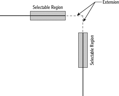
FIGURE 2.23 Selecting objects to obtain the expected result when using the FILLET command
 When the command line just reads Type a command, launch the FILLET command by choosing the Home tab Modify panel Fillet tool. Notice how the command-line interface changes after you've clicked the Fillet button (see Figure 2.24).
You can also start the FILLET command by typing F
.FIGURE 2.24 The command prompt after initiating the FILLET command
The default Fillet radius should be 0.0000 units. Like the Offset distance, the Fillet radius remains set at a constant value until you change it.
- If your command window displays a radius of 0.0000, go on to step 3. Otherwise, type R , and then type 0 to change the radius to 0.
TIP: When the radius value is set higher than 0, you can temporarily override this by holding the Shift key down while picking the two objects to be filleted. They will be filleted with a radius of 0, while the value set in the FILLET command remains unchanged.
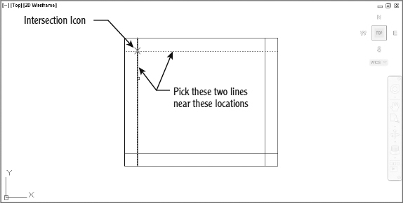
- Move the cursor—now a pickbox—to the shape, and click two intersecting lines, as shown at the top of Figure 2.25. Hovering over the second line (Figure 2.25, bottom) causes an intersection icon to appear where the fillet will occur.
FIGURE 2.25 Intersection icon displaying while picking two lines to execute the FILLET command
The intersecting lines are both trimmed to make a sharp corner (see Figure 2.26). The FILLET command automatically ends.
- Press to restart the command, and this time type M to activate the Multiple option. Multiple repeats the FILLET command until another option is initiated at the command prompt or the command is terminated with the or Esc key or the spacebar.
- Fillet the lower-left and lower-right crossing lines to clean up those corners (see Figure 2.27) and press .
FIGURE 2.27 The box with three corners cleaned up
TIP: In most cases, you'll get the same effect by pressing the spacebar as you get by pressing . The exception is when you're entering data in a text box within a dialog box or a palette; in those cases, pressing the spacebar inserts a space. - Press to restart the FILLET command. This time, type R 0.5 to set the fillet radius to 0.5, and then click the two lines that make up the interior upper-right corner.
After a command has ended, you can restart it by pressing either
or the spacebar or by right-clicking and choosing Repeat from the context menu.As you hover over the second line to fillet, notice the real-time 0.5-unit fillet preview that displays.
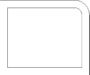
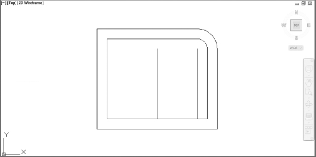
- Restart the command, set the radius to 1.0, and then fillet the outer upper-right corner. Your box should look like Figure 2.28.
FIGURE 2.28 The box with the curved radii in the upper-right corner
![]() NOTE: If you make a mistake and pick the wrong part of a line or the wrong line, press Esc to end the command and then type U
NOTE: If you make a mistake and pick the wrong part of a line or the wrong line, press Esc to end the command and then type U![]() . This will undo the effect of the last command.
. This will undo the effect of the last command.
The OFFSET and FILLET commands are a powerful combination of tools for laying out walls on a floor-plan drawing. Because these commands are so important, let's take a closer look at them to see how they work. Both commands are in the Modify panel of the Ribbon's Home tab and in the Modify menu of the menu bar, both have the option to enter a numeric value or accept the current value—for offset distance and fillet radius—and both hold that value as the default until it's changed. However, the OFFSET command keeps running until you stop it, and the FILLET command stops after each use unless the Multiple option is invoked. These commands are two of the most frequently used tools in AutoCAD. You'll learn about more of their uses in later chapters.
The down-pointing arrow next to the Fillet tool opens a fly-out menu that includes the Chamfer tool.
The FILLET command has a sister command, CHAMFER, which is used to bevel corners with straight lines. When the distances for the CHAMFER command are set to 0, you can use the command to clean up corners in the same way that you use the FILLET command. Some users prefer to use CHAMFER rather than FILLET because they don't bevel corners, but they may at times use FILLET to round off corners. If you use CHAMFER to clean up corners, FILLET can have any radius and won't have to be overridden or reset constantly to 0. You'll develop your own preference.
Completing the Shape
The final step in completing the box (Figure 2.1 from the beginning of this chapter) is to make an opening in the bottom wall. From the diagram, you can see that the opening is 2 units wide and set off from the right inside corner by 0.5 units. To make this opening, you'll use the OFFSET command twice, changing the distance for each offset, to create marks for the opening.
Offsetting Lines to Mark an Opening
Follow these steps to establish the precise position of the opening:
- At the command prompt, start the OFFSET command (Home tab Modify panel Offset tool).
Notice the command prompt. The default distance is now set at 0.5, the offset distance you previously set to offset the outside lines of the box to make the inside lines. If the distance is different, type 0.5
. You'll want to use this distance again. Press again to accept this preset distance. - Pick a point inside the vertical line on the right, and then pick a point to the left of this line. The line is offset, creating a new line 0.5 units to the left (see Figure 2.29).
FIGURE 2.29 Offsetting the first line of the opening
- Press to end the OFFSET command, and then press it again to restart the command. This will allow you to reset the offset distance.
- Enter 2 as the new offset distance, and then press .
- Click the new line, and then pick a point to the left. Press to end the OFFSET command (see Figure 2.30).
FIGURE 2.30 Offsetting the second line of the opening
You now have two new lines indicating where the opening will be. You can use these lines to form the opening when using the EXTEND and TRIM commands.
![]() TIP: The buttons you've been clicking in this chapter are also referred to as icons and tools. When they're in dialog boxes or on the status bar, they have icons (little pictures) on them and look like buttons to push. When they're on the Ribbon or toolbars, they look like icons. But when you move the pointer arrow cursor onto one, it takes on the appearance of a button with an icon on it. I use all three terms—button, icon, and tool—interchangeably throughout this book.
TIP: The buttons you've been clicking in this chapter are also referred to as icons and tools. When they're in dialog boxes or on the status bar, they have icons (little pictures) on them and look like buttons to push. When they're on the Ribbon or toolbars, they look like icons. But when you move the pointer arrow cursor onto one, it takes on the appearance of a button with an icon on it. I use all three terms—button, icon, and tool—interchangeably throughout this book.
Extending Lines
The EXTEND command is used to lengthen (extend) lines to meet other lines or geometric figures (called boundary edges). Executing the EXTEND command may be a little tricky at first until you see how it works. Once you understand it, however, it will become automatic. The command has two steps: First you pick the boundary edge or edges, and second you pick the lines you want to extend to meet those boundary edges. After selecting the boundary edges, you must press ![]() before you begin selecting lines to extend. Here are the steps:
before you begin selecting lines to extend. Here are the steps:
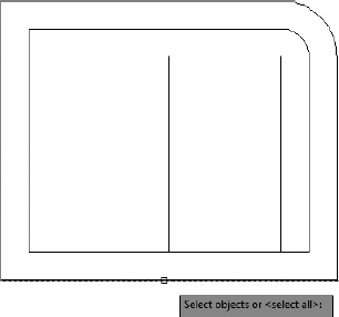
 Launch the EXTEND command by choosing Home tab Modify panel Extend tool. If you don't see the tool, click the down-arrow next to the Trim icon and then choose Extend from the fly-out menu.
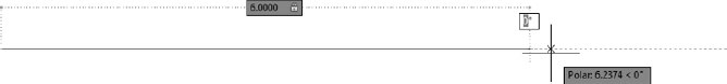
Notice that the command prompt reads Select objects or <select all>:, but, in this case, you need to observe the two lines of text above the command line in order to know that AutoCAD is prompting you to select boundary edges (see Figure 2.31).
You can also start the EXTEND command by typing EX
.FIGURE 2.31 The command window while using the EXTEND command
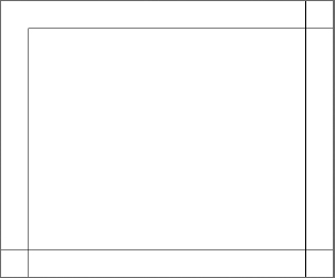
- Pick the very bottom horizontal line (see Figure 2.31) and then press .
FIGURE 2.32 Selecting a line to be a boundary edge
TIP: The Select Objects: prompt would be more useful if it read Select objects and press Enter when finished selecting objects:. But it doesn't. You have to train yourself to press when you finish selecting objects in order to get out of Selection mode and move on to the next step in the command. - Pick the two new vertical lines created by the OFFSET command. Be sure to place the pickbox somewhere on the lower halves of these lines, or AutoCAD will attempt to extend the opposite ends of the lines.
Because there are no boundary edges that could intersect with extensions from the top end of the lines, AutoCAD will ignore your picks if you select the wrong ends. The lines are extended to the boundary edge line.
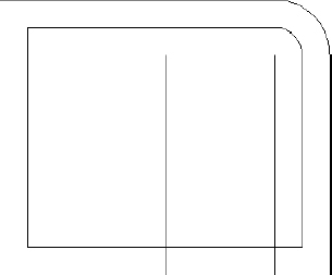
- Press to end the EXTEND command (see Figure 2.33).
FIGURE 2.33 The lines are extended to the boundary edge.
Trimming Lines
The final step is to trim away the horizontal lines to complete the opening and the unneeded portions of the two most recent vertical lines that you offset. To do this, you use the TRIM command. Like the EXTEND command, TRIM has two steps. The first is to select reference lines. In this case, they're called cutting edges because they determine the edge or edges to which a line is trimmed. The second step is to pick the lines that are to be trimmed. Also like the EXTEND command, TRIM lets you select the objects individually or use one of the many other object selection methods found inside AutoCAD. In this lesson, you'll have a chance to try out one of these methods, known as the Fence method:
- Choose the Home tab Modify panel, click the down-arrow next to the Extend button, and then choose Trim from the fly-out menu. This launches the TRIM command.
You can also start the TRIM command by typing TR
.
Notice the command-line interface. Similar to the EXTEND command, the bottom line prompts you to select objects or select everything in the drawing, but the second line up tells you to select cutting edges.
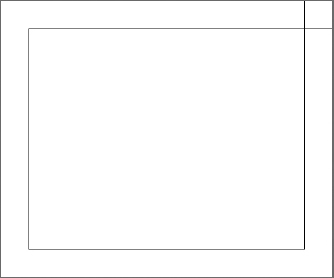
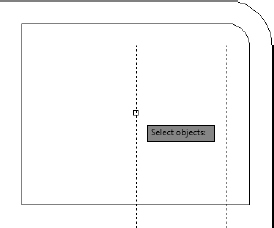
- Pick the two vertical offset lines that were just extended as your cutting edges, and then press (see Figure 2.34).
FIGURE 2.34 Lines selected to be cutting edges
- Notice that the command line reads Select object to trim or shift-select to extend or [Fence/Crossing/Project/Edge/eRase/Undo] :. Type F to start Fence mode.
- Your command line now reads Specify first fence point :. Using the Fence method, you will draw an imaginary line through the objects you want to trim. Use your cursor to draw a line that crosses the two horizontal lines across the opening, somewhere between the cutting edge lines (see Figure 2.35).
The opening is trimmed away (see Figure 2.36).
![]() NOTE: Note that in these trimming procedures, the endpoints of the cutting edge lines, as well as the lines themselves, are used as cutting edges.
NOTE: Note that in these trimming procedures, the endpoints of the cutting edge lines, as well as the lines themselves, are used as cutting edges.
![]() NOTE: If you trim the wrong line or the wrong part of a line, you can click the Undo button on the Quick Access toolbar, on the left side of the AutoCAD title bar. This undoes the last trim without canceling the TRIM command, and you can try again.
NOTE: If you trim the wrong line or the wrong part of a line, you can click the Undo button on the Quick Access toolbar, on the left side of the AutoCAD title bar. This undoes the last trim without canceling the TRIM command, and you can try again.
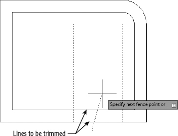
FIGURE 2.35 Lines selected to be trimmed
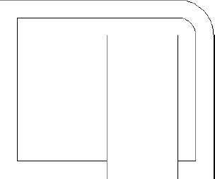
FIGURE 2.36 Lines are trimmed to make the opening.
Now let's remove the extra part of the trimming guidelines:
- Press twice—once to end the TRIM command and again to restart it. The command line asks you to Select objects or <select all>.
- Instead of selecting your cutting edges manually, you can press once again. Doing this accepts the default <select all> option listed at the command line. Using this method, every object in your drawing will be treated as a cutting edge.
- Pick the two vertical lines that extend above the new opening. Be sure to pick them above the opening (see Figure 2.37). The lines are trimmed away, and the opening is complete. Press to end the TRIM command (see Figure 2.38).
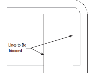
FIGURE 2.37 Lines picked to be trimmed
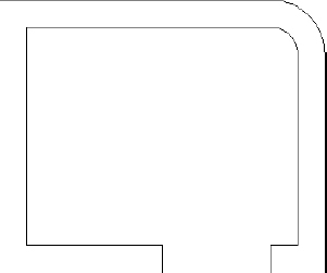
FIGURE 2.38 The completed trim
Congratulations! You've just completed the first drawing project in this book, and you've covered all the tools in this chapter. These skills will be useful as you learn how to work on drawings for actual projects.
![]() NOTE: You can check your finished shape by comparing it to Chapter02 Shape Completed.dwg, which is available from this book's website at www.sybex.com/go/autocad2013ner or www.thecadgeek.com.
NOTE: You can check your finished shape by comparing it to Chapter02 Shape Completed.dwg, which is available from this book's website at www.sybex.com/go/autocad2013ner or www.thecadgeek.com.
At this time, a valuable exercise would be to draw this box two or three more times—until you can do it without the instructions. This will serve as a confidence-builder to get you ready to take on a new challenge in the next chapter, in which you'll set up a drawing for a building.
The box you drew was 6 units by 5 units, but how big was it? You really don't know at this time because the units could represent any actual distance: inches, feet, meters, miles, and so on. Also, the box was positioned conveniently on the screen so that you didn't have any problem viewing it. What if you were drawing a building that was 200 feet (60.96 meters) long and 60 feet (18.29 meters) wide or a portion of a microchip circuit that was only a few thousandths of an inch or millimeters long? In the next chapter, you'll learn how to set up a drawing for a project of a specific size.
You can save the file by clicking the Save button on the Quick Access toolbar, or you can exit AutoCAD now without saving this drawing. To do the latter, expand the Application menu and then click the Exit AutoCAD button in the lower-right corner. When the dialog box asks whether you want to save changes, click No. Alternatively, you can leave AutoCAD open and go on to the following practice section or the next chapter.
If You Would Like More Practice…
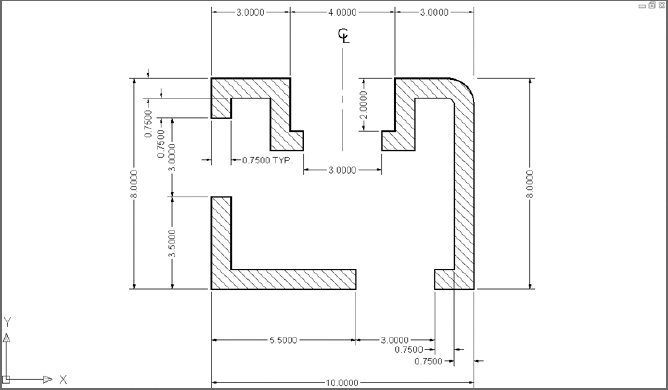
Draw the object shown in Figure 2.39.
You can use the same tools and strategy from earlier in this chapter to draw the shape. Choose New from the Application menu (Application menu ![]() New
New ![]() Drawing) to start a new drawing, and then use the acad.dwt template file. Here's a summary of the steps to follow:
Drawing) to start a new drawing, and then use the acad.dwt template file. Here's a summary of the steps to follow:
- Ignore the three openings at first.
- Draw the outside edge of the shape by using one of the relative coordinate systems. To make sure the shape fits on your screen, start the outline of the box in the lower-left corner at the absolute coordinate of 1,0.5.
- Offset the outside lines to create the inside wall.
- Fillet the corners to clean them up. (Lines that aren't touching can be filleted—just like lines that intersect.)
- Use the OFFSET, EXTEND, and TRIM commands to create the three openings.
Feel free to check your work against Chapter02 More Practice Completed.dwg on this book's web page. Don't worry about trying to put in the dimensions, centerline, or hatch lines. You'll learn how to create those objects later in the book.
Are You Experienced?
Now you can…
- Understand the basics of coordinates
- Distinguish between absolute and the two relative coordinate systems used by AutoCAD
- Input coordinates by using the direct input method
- Use the LINE, ERASE, OFFSET, FILLET, EXTEND, and TRIM commands to create a drawing