
CHAPTER 3
Setting Up a Drawing
In Chapter 2, “Learning Basic Commands to Get Started,” you explored the default drawing area that is set up when you open the AutoDesk® AutoCAD® program and start a new drawing. Using an assortment of common commands, you drew a box within the drawing area. If you drew the additional diagram offered as a supplemental exercise, the drawing area was set up the same way.
In this chapter, you'll learn how to set up the drawing area to lay out a floor plan for a building of a specific size. The decimal units that you have been using will be changed to feet and inches, and the drawing area will be transformed so that it can represent an area large enough to display the floor plan of the cabin you'll be drawing.
As you learn to set up your drawing, you'll also begin exploring ways to navigate your drawing more easily, draw lines at a specified incremental distance (such as to the nearest foot), and more. Finally, you'll save this drawing to a special folder on your hard drive. At the end of the chapter is a general summary of the various kinds of units that AutoCAD supports.
Whether or not you work in architecture, the tools you'll use and the skills you'll learn in this chapter will translate into nearly any discipline, enabling you to draw objects of any shape or size.
In this chapter, you will learn to
- Set up drawing units
- Use the AutoCAD grid
- Zoom in and out of a drawing
- Name and save a file
- Save to Autodesk® 360 Storage
Setting Up the Drawing Units
When you draw lines of a precise length in AutoCAD, you use one of five kinds of linear units. Angular units can also be any of five types. The combination you choose will largely depend on the type of drawings you plan to prepare. Each of these linear and angular units is presented at the end of this chapter, but for now let's focus on getting ready to begin drawing our cabin.
When you first start a new drawing, AutoCAD displays a blank drawing called Drawing#.dwg. By default, the linear and angular units inside this drawing are set to decimal numbers. The units and other basic setup parameters applied to this new drawing are based on a prototype drawing with default settings—including those for the units. This chapter covers some of the tools for changing the basic parameters of a new drawing so that you can tailor it to the cabin project or to your own project.
![]()
![]() NOTE: To get started with the steps in this chapter, check to be sure that each of the status bar buttons except Dynamic Input are clicked to the Off position—that is, they appear unpushed and have a gray background. Also make sure you are in model space by clicking the Quick View Layouts
NOTE: To get started with the steps in this chapter, check to be sure that each of the status bar buttons except Dynamic Input are clicked to the Off position—that is, they appear unpushed and have a gray background. Also make sure you are in model space by clicking the Quick View Layouts ![]() Model view found on the status bar. Later chapters introduce several additional status bar tools and, in Chapter 10, “Generating Elevations,” you'll see how to use templates to set up drawings.
Model view found on the status bar. Later chapters introduce several additional status bar tools and, in Chapter 10, “Generating Elevations,” you'll see how to use templates to set up drawings.
Begin by setting up new units:
- With AutoCAD running, close all drawings and then click the New button (on the Quick Access toolbar) to start a new drawing.
If the Select Template dialog box doesn't appear after you click New from the Quick Access toolbar, choose Application menu
 New Drawing.
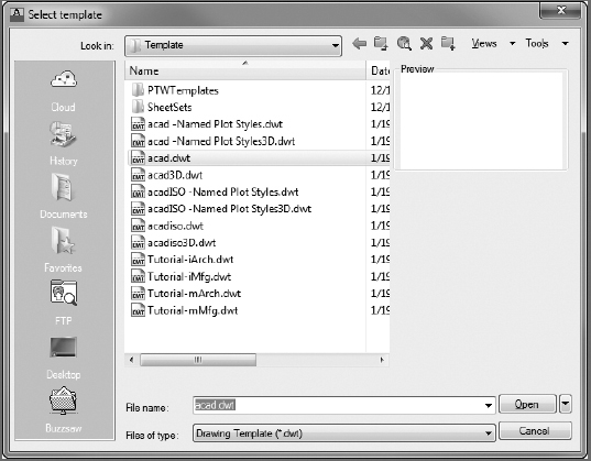
 - In the Select Template dialog box, select the acad.dwt template (see Figure 3.1) and then click Open to start a new drawing.
Choose Application menu
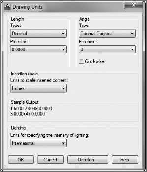
 Drawing Utilities Units to open the Drawing Units dialog box (UNITS command) shown in Figure 3.2. In the Length group, Decimal is currently selected. Similarly, in the Angle group, Decimal Degrees is the default.
IMPERIAL VS. METRIC MEASUREMENTS
From this point forward, I'll provide the metric equivalents in parentheses for readers who do not work in imperial units, the standard for architectural design in the United States. Throughout the majority of this book, you'll be developing drawings for a cabin with outside wall dimensions of 28′×18′ (8550 mm×5490 mm).
FIGURE 3.1 The Select Template dialog box
FIGURE 3.2 The Drawing Units dialog box
Within the Drawing Units dialog box, in the Length group, click the arrow in the Type drop-down list and select Architectural (metric users can leave this set to Decimal). These units are feet and inches, which you'll use for the cabin project.
Notice the two Precision drop-down lists at the bottom of the Length and Angle groups. When you changed the linear unit specification from Decimal to Architectural, the number in the Precision drop-down list on the left changed from 0.0000 to
 . At this level of precision, linear distances are displayed to the nearest
  . Metric users should set this to 0 because we won't be using units smaller than a millimeter.
Select some of the other Length unit types from the list, and notice the way the units appear in the Sample Output group at the bottom of the dialog box. Then select Architectural again or leave it set to Decimal for metric use.
 NOTE: Drop-down lists are lists of options with only the selected choice displayed when the list is closed. When you click the arrow, the list opens. When you make another selection, the list closes and your new choice is displayed. When an item on the list is selected and is the focus of the program (indicated by a blue highlight), you can change the available options by using the scroll wheel on a mouse or the up- and down-arrows on the keyboard. You can choose only one item at a time from the list.
Click the down-arrow in the Precision drop-down list in the Length group to display the choices of precision for Architectural units (see Figure 3.3).
This setting controls the degree of precision to which AutoCAD displays a linear distance. If it's set to
, any line that is drawn more precisely, such as a line  long, displays a length value to the nearest when queried (which, in the example, would be
  ). However, the line is still long.
If you change the precision setting to
 and then use the DISTANCE command to measure the distance between two features, you'll see that its length is .
- Click (0) to maintain the precision for display of linear units at (nearest millimeter).
If you open the Type drop-down list in the Angle group, you'll see a choice, among others, between Decimal Degrees and Deg/Min/Sec. Like so many set-tings in AutoCAD, the correct setting here is often dictated by the types of drawings you're preparing. Decimal angular units are the most popular choice for individuals working in architecture (or its related disciplines). On the other hand, Deg/Min/Sec is most popular in the civil engineering disciplines.
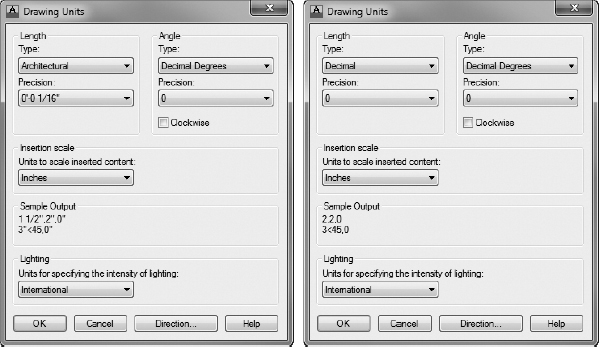
FIGURE 3.3 The Precision drop-down list for Architectural units (left) and Decimal units (right)
Because our project is a cabin (architectural), we'll use the default Decimal Degrees throughout this book. However, the default precision setting is to the nearest degree. This may not be accurate enough, so you should change it to the nearest hundredth of a degree:
Click the arrow in the Precision drop-down list in the Angle group.
NOTE: When using metric units, 1 unit = 1 millimeter.Select 0.00 as the precision value for angles.
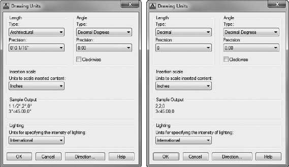
The Drawing Units dialog box will now indicate that, in your drawing, you plan to use Architectural length units with a precision of
(Decimal with a precision of 0 if using metric) and Decimal angular units with a precision of 0.00° (see Figure 3.4). This doesn't restrict the precision at which you draw, just the values that AutoCAD reports.Change the Insertion Scale to Inches (Millimeters for metric). This often overlooked setting allows AutoCAD to scale drawings automatically to the proper size when inserted or referenced into other drawings.
This behavior is common, as architects have to collaborate with civil engineers on projects. Architectural drawings are generally set up such that 1 unit is equal to 1 inch, whereas civil engineering drawings are set up such that 1 unit is equal to 1 foot. As an architect and engineer collaborate, their drawings must be scaled up by 12″ or down by
 , depending on whose drawing is being inserted. AutoCAD can automatically do this conversion for you, provided the Insertion Scale for your architectural drawings is set to Inches, and for the civil engineering drawings is set to Feet.
Clicking the Direction button at the bottom of the Drawing Units dialog box opens the Direction Control dialog box, which has settings to control the direction of 0°. By default, 0° is to the right (east), and positive angular displacement goes in the counterclockwise direction. (See Figure 2.11 in Chapter 2 for an illustration of the Cartesian Coordinate System.) These are the standard settings for most users of CAD. There is no need to change them from the defaults. If you want to take a look, open the Direction Control dialog box, note the choices, and then click Cancel. You won't have occasion in the course of this book to change any of those settings.
FIGURE 3.4 The Drawing Units dialog box for Architectural units (left), and Decimal (metric) units (right) after changes
NOTE: You'll have a chance to work with the angular units in Chapter 12, “Dimensioning a Drawing,” when you develop a site plan for the cabin.Click OK to accept the changes, and close the Drawing Units dialog box. Notice the coordinate readout in the lower-left corner of the screen: it now reads in feet and inches.
This tour of the Drawing Units dialog box has introduced you to the choices you have for the types of units and the degree of precision for linear and angular measurement. The next step in setting up a drawing is to determine its size.
![]() NOTE: If you accidentally click the mouse when the cursor is on a blank part of the drawing area, AutoCAD starts a rectangular window. I'll talk about these windows soon, but for now just press the Esc key to close the window.
NOTE: If you accidentally click the mouse when the cursor is on a blank part of the drawing area, AutoCAD starts a rectangular window. I'll talk about these windows soon, but for now just press the Esc key to close the window.
Setting Up the Drawing Size
Now that you have changed the units to Architectural, the drawing area is approximately 12″ to 16″ (500 mm) wide and 9″ (300 mm) high. You can check this by moving the crosshair cursor around on the drawing area and looking at the coordinate readout, as you did in the previous chapter.
![]() TIP: When you change Decimal units to Architectural units, 1 Decimal unit translates to 1 inch. Some industries, such as civil engineering, often use Decimal units to represent feet instead of inches. If the units in their drawings are switched to Architectural, a distance that was a foot now measures as an inch. To correct this, the entire drawing must be scaled up by a factor of 12.
TIP: When you change Decimal units to Architectural units, 1 Decimal unit translates to 1 inch. Some industries, such as civil engineering, often use Decimal units to represent feet instead of inches. If the units in their drawings are switched to Architectural, a distance that was a foot now measures as an inch. To correct this, the entire drawing must be scaled up by a factor of 12.
The drawing area is defined as the part of the screen in which you draw. You can make the distance across the drawing area larger or smaller through a process known as zooming in or zooming out. To see how this works, you'll learn about a tool called the grid that helps you to draw and to visualize the size of your drawing.
Using the Grid
The AutoCAD grid, a pattern of horizontal and vertical gridlines that mimic the appearance of a sheet of graph paper, is used as an aid to drawing. You can set the grid to be visible or invisible. When set to visible, all but two of the horizontal and vertical gridlines display with a light gray color. One vertical gridline is colored green, whereas a single horizontal gridline is colored red. These colored gridlines reside at the 0 x (red) and 0 y (green) coordinates, and they establish a boundary for Quadrant I of your drawing area, as shown in Figure 2.11 in Chapter 2.
Anything drawn above the red gridline and to the right of the green gridline will reside in Quadrant I, having positive x- and y-coordinate values. When working in 3D, the green and red gridlines will still represent the positive x- and y-coordinates of your drawing area graphically; however, a third z-axis will also be represented in blue. Don't worry too much about the z-axis quite yet, as it will be discussed in Chapter 16, “Creating 3D Geometry,” and Chapter 17, “Rendering and Materials.”
The area covered by the grid depends on a setting called Drawing Limits, explained in the section “Setting Up Drawing Limits,” later in this chapter. To learn how to manipulate the grid size, you'll make the grid visible, use the Zoom In and Zoom Out commands to vary the view of the grid, and then change the area over which the grid extends by resetting the drawing limits.
Before doing this, however, let's take a look at the icon that sits in the lower-left corner of the drawing area. This icon is known as the UCS, or user coordinate system, icon. The UCS icon provides a visual cue to how we're looking at the drawing, and it will change when we're looking from a 3D perspective. You'll learn more about this in Chapter 10 when we begin our discussion of 3D. To become familiar using and interacting with the grid in AutoCAD, follow these steps:
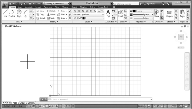
Move the crosshair cursor to the status bar at the bottom of the screen, and click the Grid Display button.
The button changes from the Off to the On state (with a light blue background), and a series of horizontal and vertical lines appear in the drawing area, representing a piece of graph paper.
These lines are the grid. Preset by default to be
 (10 mm) apart, they extend across the entire drawing area. In the drawing area, the gridlines may measure a greater distance apart, especially if you zoom out in the drawing. This is because, in the relatively large drawing area, lines spaced (10 mm) apart would be very dense, and working with them would be difficult. AutoCAD automatically reduces the density of the displayed gridlines to maintain a reasonable appearance in the drawing area.
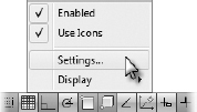
To open the Drafting Settings dialog box, right-click the Grid Display button and then choose Settings from the context menu that appears (see Figure 3.5).
FIGURE 3.5 Displaying the Drafting Settings dialog box
 TIP: Right-clicking any of the buttons (except Ortho Mode, Allow/Disallow Dynamic UCS, and Show/Hide Transparency) on the left side of the status bar and choosing Settings opens the Drafting Settings dialog box (or other appropriate dialog box for defining the tool's parameters) to the tab with the parameters that relate to that specific button. You can also open the Drafting Settings dialog box by typing DS
 .
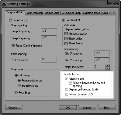
.The Snap And Grid tab of the Drafting Settings dialog box should be active (see Figure 3.6). If it's not, click the tab.
FIGURE 3.6 The Snap And Grid tab of the Drafting Settings dialog box
In the Grid Behavior group, be sure Adaptive Grid is checked and Display Grid Beyond Limits is unchecked. Then click OK.
The grid now covers only the area from the origin to 12″, 9″ (490 mm, 290 mm), the area defined by the limits of the drawing, but extends to the extents of the drawing area. This will be evident after this step.
Limits are discussed in the next section. The Adaptive Grid option causes AutoCAD to reduce the number of the grid's columns and rows proportionately whenever the zoom factor would cause the grid to become too dense to be effective.
 To display a larger area within the drawing area, scroll the mouse wheel by dragging it toward you or use the Zoom Out command by clicking the drop-down arrow next to the Zoom tool from the View tab Navigate 2D panel on the Ribbon.
The view changes, and there are more gridlines in a denser configuration (see Figure 3.7). You may need to zoom twice to see the effect. Move the crosshair cursor to the lower-left corner of the grid, and then move it to the upper-right corner. Notice that the coordinate readout at the lower left of your screen now shows a large negative number for the lower-left corner and a larger positive number for the upper-right corner. You're displaying a greater amount of space in the drawing area. A closer inspection of the grid will reveal one vertical line colored green and a horizontal line colored red. Where these lines intersect represents the origin, or 0,0 point, inside your drawing. Any point above the red line and to the right of the green line will have a positive coordinate value.
FIGURE 3.7 The grid after zooming out
 To the left of the Grid Display button on the status bar, click the Snap Mode button. Then move the cursor back onto the grid and look at the coordinate readout again.
The cursor stops at each grid point intersection, even those that are no longer displayed because of the zoom factor, and the readout is to the nearest half inch. The Snap tool locks the cursor onto the gridlines; even when the cursor isn't on the visible grid but somewhere outside it on the drawing area, the cursor maintains the grid spacing and jumps from one location to another.
CURSOR MOVING ERRATICALLY?
The Snap tool can be an incredibly powerful drawing aid when you turn it on intentionally. However, because the grid doesn't have to be on to use Snap, many users accidentally enable the Snap tool and then report that their cursor is moving erratically. If this happens to you at some point, remember to verify that your Snap is turned off to restore the “normal” fluid movement of the cursor.
- Use the Zoom Out command a few more times or scroll the mouse wheel.
 From the View tab Navigate 2D panel, choose Zoom Zoom In, or roll the scroll wheel on your mouse enough times to bring the view of the grid back to the way it appeared when it was first displayed. You aren't changing the size of the grid, just the view of it. It's like switching from a normal to a telephoto lens on a camera.
The grid is more of a guide than an actual boundary of your drawing. For most purposes, you can draw anywhere on the screen. The grid merely serves as a tool for visualizing how your drawing will be laid out.
Because it serves as a layout tool for this project, you need to increase the area covered by the grid from its present size to 60′×40′ (18 m×12 m).
Setting Up Drawing Limits
The Drawing Limits setting defines two properties in a drawing: it records the coordinates of the lower-left and upper-right corners of the grid and identifies what is displayed when the user executes a Zoom ![]() All command with only a small portion of the drawing area in use. The coordinates for the lower-left corner are 0,0 by default and are usually left at that setting. You need to change only the coordinates for the upper-right corner and change the settings so that the grid is displayed only within the limits:
All command with only a small portion of the drawing area in use. The coordinates for the lower-left corner are 0,0 by default and are usually left at that setting. You need to change only the coordinates for the upper-right corner and change the settings so that the grid is displayed only within the limits:
Make sure the command window displays the Type a command: prompt; then type LIMITS
. Notice how the command-line interface appears, as shown in Figure 3.8.The command line tells you that the first step is to decide whether to change the default x- and y-coordinates for the lower-left limits, both of which are currently set at 0′−0″, 0′−0″ (0,0). There is no need to change these.
FIGURE 3.8 The command window after starting the LIMITS command
- Press to accept the 0′−0″,0′−0″ (0,0) coordinates for this corner. The command line changes, and it now displays the coordinates for the upper-right corner of the limits. This is the setting you want to change.
Type 60′, 40′ (18000,12000)
. Be sure to include the foot sign (′). NOTE: AutoCAD requires that, when using Architectural units, you always indicate that a distance is measured in feet by using the foot sign (′). You don't have to use the inch sign (″) to indicate inches. To bring the entire area defined by the drawing limits onto the screen, use the ZOOM command again, but this time use the All option to bring the drawing limits into view (see Figure 3.9).
From the View tab
Navigate 2D panel, click the down-arrow next to the Zoom tool and then click the All option, or type Z A. The All option zooms the view to display all the objects in the drawing or, in a blank drawing, zooms to the limits. The drawing area expands to display the drawing limits, and the grid changes appearance to accommodate the new view.- Move the cursor from one gridline to another and watch the coordinate readout. The coordinates are still displayed to the nearest half-inch (10 mm), but the gridlines are much more than half an inch (10 mm) apart.
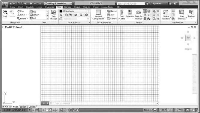
FIGURE 3.9 The drawing with the grid extending to the 60′×40′ (18,000 mm×12,000 mm) limits
By default, when you zoom in or out, AutoCAD adjusts the grid spacing to keep the gridlines from getting too close together or too far apart. In this case, remember that you found the grid spacing to be ![]() (10 mm) by default. If the drawing area is giving you a view of a 60′×40′ (18,000 mm×12,000 mm) grid with gridlines at
(10 mm) by default. If the drawing area is giving you a view of a 60′×40′ (18,000 mm×12,000 mm) grid with gridlines at ![]() (10 mm), the grid has 1440 (1800) vertical gridlines and 960 (1200) horizontal gridlines. If the whole grid were to be shown on the screen, the gridlines would be so close together that they would be only about 1 pixel in size and would solidly fill the drawing area. So, AutoCAD adjusts the spacing of the dots to keep the grid readable. You need to change that spacing to a more usable value.
(10 mm), the grid has 1440 (1800) vertical gridlines and 960 (1200) horizontal gridlines. If the whole grid were to be shown on the screen, the gridlines would be so close together that they would be only about 1 pixel in size and would solidly fill the drawing area. So, AutoCAD adjusts the spacing of the dots to keep the grid readable. You need to change that spacing to a more usable value.
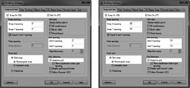
For the drawing task ahead, it will be more useful to have the spacing set differently. Remember how you turned on Snap mode and the cursor stopped at each gridline intersection? If you set the gridline spacing to 2′ (1000 mm) and the Snap Spacing to 6″ (50 mm), you can use Grid and Snap modes to help you draw the outline of the cabin, because the dimensions of the outside wall line are in whole feet (millimeters) and divisible by 2. The dimensions of the outside wall line are 28′×16′ (8550 mm×4850 mm), and the exterior walls are 6″ (150 mm) thick. Here's how:
Right-click the Grid Display button on the status bar, and click Settings to open the Drafting Settings dialog box one more time.
The Drafting Settings dialog box opens, and the Snap And Grid tab is active. The settings in both the Grid Spacing and Snap Spacing groups include X and Y Spacing settings. Notice that they're all set for a spacing of
(10).In the Grid Spacing group, click in the Grid X Spacing text box and change
(10) to 2′ (1000), as shown in Figure 3.10. Then click in the Grid Y Spacing text box. It automatically changes to match the Grid X Spacing text box.If you want different Grid X and Grid Y Spacing values, you must deselect the Equal X And Y Spacing option in the Snap Spacing group.
FIGURE 3.10 New settings on the Snap And Grid tab of the Drafting Settings dialog box using imperial units (left) and metric units (right)
- In the Snap Spacing group, change the Snap X Spacing setting to 6 (50), as shown in Figure 3.10. The inch sign isn't required. Then click the Snap Y Spacing input box or press the Tab key. The Snap Y spacing automatically changes to match the Snap X Spacing setting.
If you set Grid Spacing to 0, the grid takes on what-ever spacing you set for the Snap X Spacing and Snap Y Spacing text boxes. This is how you lock the snap and grid together.
- In the Snap Type group, be sure Grid Snap and Rectangular Snap are selected (Figure 3.10).
- In the Grid Behavior group, only Adaptive Grid should be selected. With the grid set this way, AutoCAD will adjust the number of grid-lines displayed as you zoom in and out, but it won't add gridlines between the lowest grid spacing.
- The Snap On and Grid On check boxes at the top of the dialog box should be selected. If they aren't, click them. Your Snap And Grid tab should look like Figure 3.10.
- Click OK. The new 2′ (1000 mm) grid is now visible. Move the cursor around on the grid—be sure Snap is on. (Check the Snap Mode button on the status bar; it's pressed when Snap is on.) Notice the coordinate readout. It's displaying coordinates to the nearest 6″ (50 mm) to conform to the new 6″ (50) snap spacing. The cursor stops at several snap points between each grid dot.
- Move the crosshair cursor to the upper-right corner of the grid, and check the coordinate readout. It should display 60′-0″, 40′-0″, 0′-0″ (18000.0000, 12000.0000, 0). In AutoDesk® AutoCAD LT®, you won't have the third coordinate.
Drawing with Grid and Snap
Your drawing area now has the proper settings, and it is zoomed to a convenient magnification. You're ready to draw the first lines of the cabin:
- When the command window displays the Type a command: prompt, start the LINE command.
- From the Home tab Draw panel, click the Line button or type L.
- Type 8′, 8′ (2500,2500), or move the cursor until the Dynamic Input fields indicate the cursor is over the 8′, 8′ (2500, 2500) point.
- Click to define the starting point of the line.
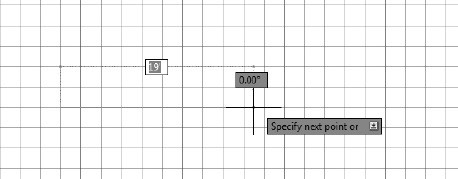
Hold the crosshair cursor above and to the right of the point you just picked.
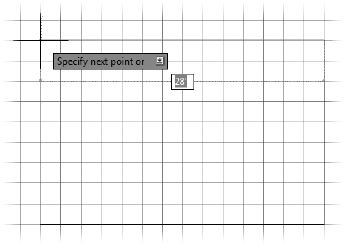
AutoCAD shows ghosted linear and angular dimensions that dynamically display the length and angle of the first line segment as the cursor moves, and a tooltip window displays the current prompt for the LINE command (see Figure 3.11).
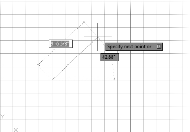
- Don't click yet. Hold the crosshair cursor directly out to the right of the first point picked, and note how the linear dimension displays a distance in 6″ (50 mm) increments. The angular dimension should have an angle of 0.00°, as shown in Figure 3.12.
- Continue moving the crosshair cursor left or right until the dashed linear dimension displays 28′ (8550).
At this point, click the left mouse button to draw the first line of the cabin wall (see Figure 3.13).
FIGURE 3.11 One point picked on the grid
FIGURE 3.12 Setting the angle for the first line
FIGURE 3.13 The first line of the cabin wall is drawn.
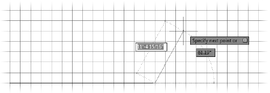
- Move the crosshair cursor directly above the last point picked to a position such that the dashed linear dimension displays 18′ (5490) and the dashed angular dimension displays 90.00°, and then pick that point.
Move the crosshair cursor directly left of the last point picked until the dashed linear dimension displays 28′ (8550) and the dashed angular dimension displays 180.00°, and then pick that point (see Figure 3.14).
FIGURE 3.14 Drawing the second and third wall lines
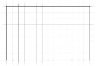
Finally, type C
to close the box.This tells AutoCAD to draw a line from the last point picked to the first point picked and, in effect, closes the box. AutoCAD then automatically ends the LINE command (see Figure 3.15).
FIGURE 3.15 The completed outside wall lines
This method for laying out building lines by using Snap and Grid and Dynamic Input is useful if the dimensions all conform to a convenient rounded-off number, such as the nearest 6 inches. The key advantage to this method over just typing the relative coordinates, as you did with the box in Chapter 2, is that you avoid having to enter the numbers. You should, however, assess whether the layout you need to draw has characteristics that lend themselves to using Grid, Snap, and Dynamic Input or whether typing the relative coordinates would be more efficient. As you get more comfortable with AutoCAD, you'll see that this sort of question comes up often: which way is the most efficient? This happy dilemma is inevitable in an application with enough tools to give you many strategic choices. In Chapters 4 and 5, “Developing Drawing Strategies: Parts 1 and 2,” you'll learn other techniques for drawing rectangles.
Taking a Closer Look at Dynamic Input
![]() The kind of information shown in dynamic display is similar to that shown in the command-line interface, and the intent of this feature is to keep your eyes on the screen as much as possible. The specific information displayed depends, as it does on the command line, on what you're doing at the time. It's controlled by several settings that you access by right-clicking the Dynamic Input button on the status bar and selecting Settings from the context menu. This opens the Drafting Settings dialog box with the Dynamic Input tab activated (see Figure 3.16).
The kind of information shown in dynamic display is similar to that shown in the command-line interface, and the intent of this feature is to keep your eyes on the screen as much as possible. The specific information displayed depends, as it does on the command line, on what you're doing at the time. It's controlled by several settings that you access by right-clicking the Dynamic Input button on the status bar and selecting Settings from the context menu. This opens the Drafting Settings dialog box with the Dynamic Input tab activated (see Figure 3.16).
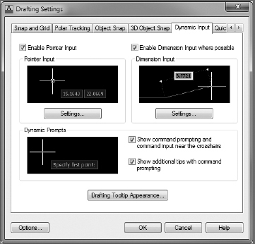
FIGURE 3.16 The Dynamic Input tab of the Drafting Settings dialog box
This tab has four check boxes (two at the top, and two near the middle on the right) and three buttons to open three feature-specific Settings dialog boxes. To make the dynamic input conform to what is shown in the book, do the following:
- Make sure all four check boxes are selected.
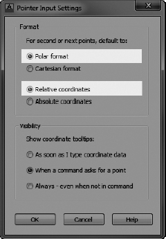
In the Pointer Input group, click the Settings button to open the Pointer Input Settings dialog box (see Figure 3.17).
FIGURE 3.17 The Pointer Input Settings dialog box
- In the Format group, the Polar Format and Relative Coordinates radio buttons should be selected. Click OK.
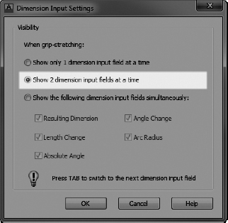
- In the Dimension Input group of the Drafting Settings dialog box, click the Settings button to open the Dimension Input Settings dialog box (see Figure 3.18).
- Make sure the Show 2 Dimension Input Fields At A Time radio button is selected, and then click OK.
- In the Dynamic Prompts group of the Drafting Settings dialog box, ensure that both Show Command Prompting And Command Input Near The Crosshairs and Show Additional Tips With Command Prompting are checked.
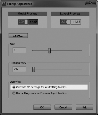
- Below the Dynamic Prompts group of the Drafting Settings dialog box, click the Drafting Tooltip Appearance button to open the Tooltip Appearance dialog box (see Figure 3.19).
FIGURE 3.18 The Dimension Input Settings dialog box
FIGURE 3.19 The Tooltip Appearance dialog box
In the Apply To group at the bottom of the box, ensure that the Override OS Settings For All Drafting Tooltips radio button is selected. Vary the Colors, Size, and Transparency settings according to your preference. (I used a setting of 0 for Size and 0% for Transparency.) Don't worry about Layout Color for now. The Model Color you choose depends on whether your drawing area has a light or dark background. Experiment. When you're finished, click OK.
- Click OK again to close the Drafting Settings dialog box.
If you decide to disable Dynamic Input, you can easily do so by clicking its button in the status bar so that it's in unpushed mode (with a gray background).
Saving Your Work

Expanding on the previous options of saving drawings to either a local or network drive, AutoCAD 2013 introduces the ability to save drawings to a cloud storage service named Autodesk 360 Storage. Many companies have very specific file management policies defining how drawings should be stored. These policies typically direct users to store drawings on a network drive that's backed up on a regular basis, guarding against the loss of data due to the failure of a hard drive or other such incident.
While network drives are incredibly efficient for design teams who are collocated, it introduces challenges to teams that are geographically dispersed or lack such network infrastructure altogether. Autodesk 360 Storage introduces an option for both scenarios and provides anywhere, anytime access to your drawings. Depending on your specific needs to share and exchange designs, you'll likely find it worthwhile to employ the local and network drive structure in tandem with Autodesk 360 Storage.
Saving Drawings to Your Hard Drive or Network Drive
As in all Windows-compliant applications, when you save an AutoCAD file for the first time by choosing Save, you can designate a name for the file and a folder in which to store it. I recommend that you create a special folder, called something like AutoCAD NER, for storing the files you'll generate as you work your way through this book. This will keep them separate from project work already on your computer, and you'll always know where to save or find a training drawing. To save your drawing, follow these steps:
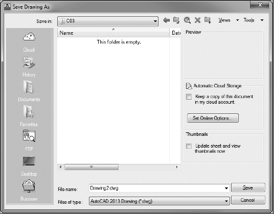
 In AutoCAD, click the Save button on the Quick Access toolbar or choose Save from the Application menu. Because you haven't named this file yet, the Save Drawing As dialog box opens, as shown in Figure 3.20.
FIGURE 3.20 The Save Drawing As dialog box
The Save button in the Quick Access toolbar, the Application menu
Save option, and the Ctrl+S key combination actually invoke the QSAVE (Quick Save) command in AutoCAD. QSAVE asks for a filename only when the drawing has not yet been saved for the first time, after which it simply overwrites the existing file without prompting. Entering the SAVE command at the command line (SAVE) always opens the Save Drawing As dialog box, where the filename and path are modified. NOTE: The actual folders and files may be different on your computer.- In the Save In drop-down list, designate the drive and folder where you want to save the drawing. If you're saving it on the hard drive or server, navigate to the folder in which you want to place the new AutoCAD NER folder.
 Click the Create New Folder button near the top-right corner of the dialog box. The folder appears in the list of folders and is highlighted. It's called New Folder, and a cursor flashes just to the right of the highlighting rectangle.
- Type AutoCAD NER (or whatever name you want to give the new folder).
- Double-click the new folder to open it.
In the File Name box, change the name to I03A-FPLAYO (M03A-FPLAYO). You're not required to enter the .dwg extension.
NOTE: Imperial (feet and inches) drawings for this book carry an I prefix, and metric an X prefix, in their filenames. Drawings for individual exercises are prefixed with the chapter number and sequentially numbered. The final drawing in each chapter follows the National CAD Standard structure and is the file you should use to begin the succeeding chapter.- Click Save. Notice that the AutoCAD title bar displays the new name of the file along with its path. It's now safe to exit AutoCAD.
- If you want to shut down AutoCAD at this time, choose Application menu Exit AutoCAD or click the X button in the top-right corner of the AutoCAD window. Otherwise, keep your drawing up and read on.
![]() TIP: Each time you save, check your work against the online project files. Throughout the book, you will be directed to save your cabin project in progress at major stages. Files corresponding to each stage where you save your files are available on this book's web page: www.sybex.com/go/autocad2013ner.
TIP: Each time you save, check your work against the online project files. Throughout the book, you will be directed to save your cabin project in progress at major stages. Files corresponding to each stage where you save your files are available on this book's web page: www.sybex.com/go/autocad2013ner.
![]() TIP: You can also access a full range of additional resources including tutorials, videos, and more that are specific to the exercises in this book from www.thecadgeek.com.
TIP: You can also access a full range of additional resources including tutorials, videos, and more that are specific to the exercises in this book from www.thecadgeek.com.
U.S. NATIONAL CAD STANDARD (NCS)
Where applicable, this book will employ the U.S. National CAD Standard (NCS). Over the last several years, the popularity of this standard has grown immensely, and it is now in use by many of the top architectural and engineering firms in the United States. You'll learn more about the NCS when you begin learning about layers, but for now we'll stick to file naming. According to the NCS, our cabin drawing is considered a model drawing, whose standard file-naming structure is as follows:
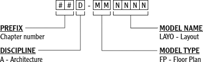
The discipline portion of an NCS filename must be one of the predefined single-letter codes listed in Chapter 6, “Using Layers to Organize Your Drawing,” which explores the naming convention as applied to layer names.
The U.S. National CAD Standard has proven flexible enough to support firms both large and small. By working through this book, you'll get a good introduction to how the NCS works. If, after reading this book, you would like to learn more about the National CAD Standard, visit http://nationalcadstandard.org.
From now on, when you're directed to save the drawing, save it as X##A-FPLAYO, with X representing the unit of measure (I: imperial, M: metric), and ## indicating the two-digit number of the chapter (for example, 03 for Chapter 3). This way, you'll know where in the book to look for review, if necessary. To save the current drawing under a different name, use the Save As command (Application menu ![]() Save As, or SAVEAS
Save As, or SAVEAS![]() ).
).
Saving Drawings to Autodesk 360 Storage
Storing files online, or as it's sometimes better known—in the cloud—is becoming commonplace as design teams are increasingly mobile and geographically dispersed. In addition to saving drawings on a file server, or even on your local workstation, it's now possible to keep a copy of your designs in the cloud. This is facilitated by a service from Autodesk known as Autodesk 360 Storage.
A free version of Autodesk 360 Storage is openly available by visiting http://360.autodesk.com. After completing your account registration, you can save your drawings to the cloud as follows:
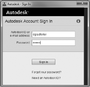
- Click the Sign In button on the InfoCenter toolbar, and choose Sign In To Autodesk 360 from the menu that opens. The Autodesk - Sign In dialog box opens.
From the Autodesk - Sign In dialog box, enter the username and password you used to register your account at http://360.autodesk.com, as shown in Figure 3.21. Once signed in, your user-name will appear on the InfoCenter toolbar.
FIGURE 3.21 Signing in to the Autodesk 360 service
 The Cloud Options button displays on the Quick Access toolbar upon signing in to the Autodesk 360 service. Clicking this button and then selecting Keep A Copy Of This Document In My Autodesk 360 Account is the quickest and easiest way to upload your drawing to the cloud.
When enabled, a copy of your drawing will automatically upload to your Autodesk 360 Storage account the next time you save your drawing. Several collaboration options, such as AutoCAD® WS, exist after a drawing is uploaded to the cloud.
As part of the Autodesk 360 offering, AutoCAD WS is a free multiplatform design collaboration platform offering more than 100 of the tools found inside the desktop version of AutoCAD covered in this book. Integrating with Autodesk 360 Storage, AutoCAD WS can open DWG and DXF files without installing any software. Simply browse to http://autocadws.com to begin viewing, editing, sharing, and collaborating on designs within your favorite web browser.
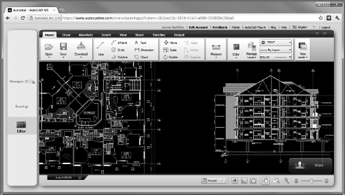
In addition to the web interface found at http://autocadws.com, mobile and desktop AutoCAD WS clients also exist for several platforms including iOS (Apple iPhone and iPad), Android, and the OS X operating system.
Understanding AutoCAD Units
The following is a brief description of each of the linear and angular unit types that AutoCAD offers and how they are used. The example distance is ![]() . The example angle is 126°35′10″.
. The example angle is 126°35′10″.
Linear Units
The linear unit types that AutoCAD uses are as follows:
Architectural This unit type uses feet and inches with fractions. You must use the foot sign (′): for example, ![]() . For this distance, enter 2′6-1/2 or 2′6.5. For the most part, these are the units that you'll use in this book.
. For this distance, enter 2′6-1/2 or 2′6.5. For the most part, these are the units that you'll use in this book.
Decimal This unit type uses decimal units that can represent any linear unit of measurement. You don't use the foot sign, the inch sign, or fractions. This method is especially common in the civil engineering discipline, where decimal units are used, and 1 unit is equal to 1 foot. Therefore, for the distance ![]() , you would need to convert the inches (6.5 inches in this case) to the decimal equivalent of a foot
, you would need to convert the inches (6.5 inches in this case) to the decimal equivalent of a foot ![]() . So in this case, you would enter 2.5417.
. So in this case, you would enter 2.5417.
Let's say you needed to draw a line 10′3″ long in a drawing where 1 unit was equal to 1 foot. You would need to convert the inches to the decimal equivalent of a foot. So in this case, ![]() and so you would enter 10.25.
and so you would enter 10.25.
Conversely, if each unit was equal to an inch, that same ![]() line would be entered as 30.5 because (2×12) + 6 = 30 and
line would be entered as 30.5 because (2×12) + 6 = 30 and ![]() .
.
Engineering This unit is equivalent to Architectural units except that inches are displayed as decimals rather than fractions. For a distance of ![]() , enter 2′6.5 or 2.5417′. In either method, the resulting distance is displayed as 2′-6.5″.
, enter 2′6.5 or 2.5417′. In either method, the resulting distance is displayed as 2′-6.5″.
Fractional These units are just like Architectural units except there is no use of feet. Everything is expressed in inches and fractions. If you enter 30-1/2 or 30.5, the resulting distance displays as ![]() .
.
Scientific This unit system is similar to the Decimal unit system except for the way in which distances are displayed. If you enter 3.05E+01, that is what is displayed. The notation always uses an expression that indicates a number from 1 to 10 that is to be multiplied by a power of 10. In this case, the power is 1, so the notation means 3.05×10, or 30.5 in Decimal units.
Angular Units
The angular unit types that AutoCAD uses are as follows:
Decimal This type uses 360° in a circle in decimal form, with no minutes and no seconds. All angles are expressed as decimal degrees. For example, an angle of 126°35′10″ is entered as 126.586 or 126d35′10″ and displays as 126.5861. AutoCAD uses the letter d instead of the traditional degree symbol (°).
Deg/Min/Sec This is the traditional system for measuring angles. In AutoCAD notation, degrees are indicated by the lowercase d, the minutes use the traditional ′, and the seconds use the traditional″. The use of this system is generally reserved for the civil engineering discipline. Most other users now use decimal angles instead and choose their preference for precision.
Grads This unit is based on a circle being divided into 400 grads, so 90° equals 100 grads. One degree equals 1.11 grads, and 1 grad equals 0.90 degrees. AutoCAD uses g as the symbol for grads.
Radians The radian is the angle from the center of a circle made by the radius of the circle being laid along the circumference of the circle.
One radian equals 57.3°, and 360° equals 6.28 radians, or 2π radians. AutoCAD uses r as the symbol for radians.
Surveyor These units use bearings from the north and south directions toward the east or west direction and are expressed in degrees, minutes, and seconds. They're discussed in Chapter 12. In this example, 126°35′10″ translates to N 36d35′10″ W in bearings, or Surveyor's units.
The tools covered in this chapter are your keys to starting a new drawing from scratch and getting it ready for a specific project. The next chapter focuses on adding to the drawing, modifying the commands you learned as part of Chapter 2, and creating strategies for solving problems that occur in the development of a floor plan.
Are You Experienced?
Now you can…
- Set up linear and angular units for a new drawing
- Make the grid visible and modify its coverage
- Use the Zoom In and Zoom Out commands
- Activate Snap mode and change the snap and grid spacings
- Use the Zoom All function to fit the grid on the drawing area
- Draw lines by using the Grid, Snap, and Dynamic Input features
- Create a new folder on your hard drive from within AutoCAD
- Name and save your file