CHAPTER 8
Controlling Text in a Drawing
You have many uses for text in your drawings, including titles of views, notes, and dimensions. It's not uncommon for the majority of a page to be covered with text outlining pertinent information such as titles, design requirements, and other project details. Each of these might require a different height, orientation, justification, and style of lettering. To control text, you'll need to learn how to do the following:
- Set up text styles to determine how the text will look
- Specify where the text will be, and enter it in the drawing
- Modify the text already in your drawing
Autodesk® AutoCAD® software offers several annotation tools you'll learn to combine in this chapter to help tell the story of your design. For example, you may choose to apply single-line text for titles, whereas multiline text is likely to be better suited for the large blocks of text typical of longer notes.
You'll progress through this chapter by first looking at the process of setting up text styles. You'll then start placing and modifying single-line text in the cabin drawing. Finally, you'll look at the methods for creating and controlling multiline text as it's used for notes and tables. If you work in a non-AEC (architecture, engineering, and construction) profession or trade, be assured that the features presented in this chapter will apply directly to your work. The basic principles of working with text in AutoCAD and Autodesk® AutoCAD LT® programs apply universally..
In this chapter, you will learn to
- Set up text styles
- Place new text, and modify existing text in a drawing
- Work with gridlines, add hyperlinks, and use Spell Check
Setting Up Text Styles
In AutoCAD, a text style consists of a combination of a style name, a text font, a height, a width factor, an oblique angle, and a few other mostly static settings. You specify these text style properties with the help of a dialog box that opens when you start the STYLE command. You'll begin by setting up two text styles—one for labeling the rooms in the floor plan and the other for putting titles on the two views. You'll need a new layer for text:
- Open the I07A-FPLAYO.dwg (M07A-FPLAYO.dwg) drawing.
- Zoom out so that you can see the entire drawing.
- Create a new layer named A-ANNO-TEXT. Assign it the color Yellow (2) and make it current.
- Thaw all the other layers.
- Click the Annotate tab to display the panels relevant to text and dimensioning, and save the file as I08-01-TextLayer.dwg (M08-01-TextLayer.dwg).
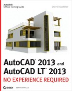
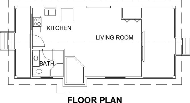
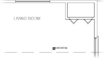
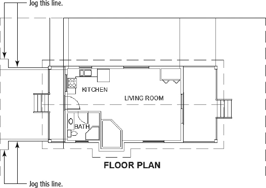
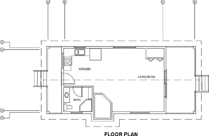
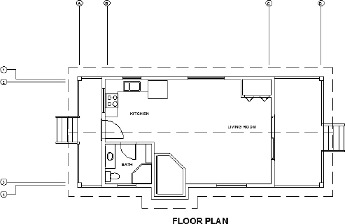
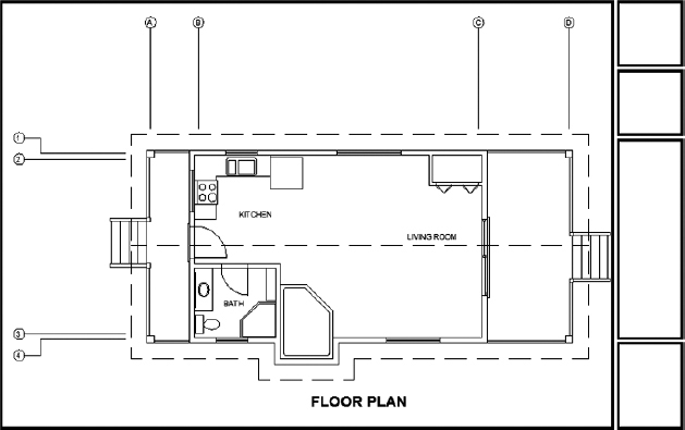
Your drawing should look like Figure 8.1.
FIGURE 8.1 The I08-01-TextLayer.dwg (M08-01-TextLayer.dwg) drawing with all layers displayed
Determining Text and Drawing Scale
When you set up text styles for a drawing, you have to determine the height of the text letters. To make this determination, you first need to decide the scale at which the final drawing will be printed.
In traditional drafting, you can ignore the drawing scale and set the actual height of each kind of text. This is possible because, although the drawing is to a scale, the text doesn't have to conform to that scale and is drawn full size.
In AutoCAD, a feature called layouts makes it possible to set the height of text in the same way—that is, at the height at which it will be printed. You'll learn about using layouts in Chapter 14, “Using Layouts to Set Up a Print.” In that chapter, you'll place text on layouts. In this chapter, I'll demonstrate how you use text without layouts. You'll place text in the cabin drawing. The drawing is actual size, but the text has to be much larger than actual size because both the drawing and its text will be scaled down by the same factor in the process of printing the drawing.
A layout is a drawing environment that has been overlaid on the drawing of your project. The layout and the drawing are part of the same file.
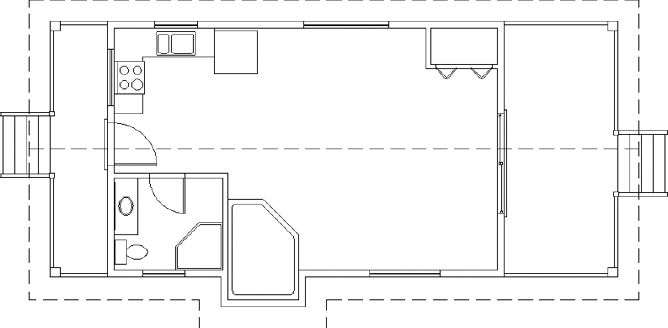
In this drawing, you'll use a final scale of ![]() (1:50). This scale has a true ratio of 1:48 (1:50) and a scale factor of 48 (50). Table 8.1 lists the AutoCAD standard scales and corresponding ratios. If you want text to be
(1:50). This scale has a true ratio of 1:48 (1:50) and a scale factor of 48 (50). Table 8.1 lists the AutoCAD standard scales and corresponding ratios. If you want text to be ![]() (3.5 mm) high when you print the drawing at
(3.5 mm) high when you print the drawing at ![]() (1:50) scale, multiply
(1:50) scale, multiply ![]() (3.5 mm) by the scale factor of 48 (50) to get 6″ (175 mm) for the text height. You calculate the imperial scale factor by inverting the scale fraction
(3.5 mm) by the scale factor of 48 (50) to get 6″ (175 mm) for the text height. You calculate the imperial scale factor by inverting the scale fraction ![]() and multiplying it by 12. You can check that calculated text height by studying the floor plan for a moment and noting the sizes of the building components represented in the drawing. The stair tread depth is 10″, and the text will be slightly smaller.
and multiplying it by 12. You can check that calculated text height by studying the floor plan for a moment and noting the sizes of the building components represented in the drawing. The stair tread depth is 10″, and the text will be slightly smaller.
TABLE 8.1: Standard scales and their corresponding ratios
Similarly, when using decimal units, the scale factor is derived by dividing the second number in the ratio by the first—for example, 1:50 has a scale factor of 50, and 1:60 has a scale factor of 60.
Defining a Text Style for View Titles
Now that you have a good idea of the required text height, it's time to define a new text style. Each new AutoCAD DWG file comes with two predefined text styles: Standard and Annotative. They reflect the two types of text styles that you can create inside AutoCAD. You'll learn more about Annotative text styles in the next exercise. For now, we'll focus only on Standard text styles, or static text styles as they're sometimes called.
To create Standard text styles, you must calculate the correct Model Space Text Height setting so that your text will plot at the correct height when your drawing is plotted at scale. For this exercise, you'll create a text style for text that will be plotted at a scale of ![]() . To get started with your first text style, follow these steps:
. To get started with your first text style, follow these steps:
- Make sure I08-01-TextLayer.dwg (M08-01-TextLayer.dwg) is open.
 On the Home tab
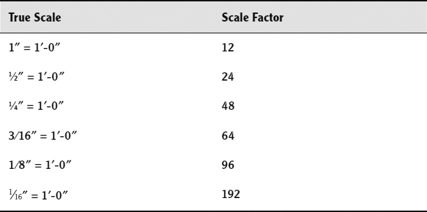
  expanded Annotation panel, click the Text Style button (see Figure 8.2), or enter ST
 to start the STYLE command.
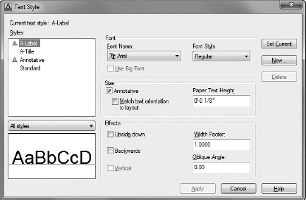
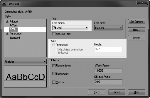
After you start the STYLE command, the Text Style dialog box shown in Figure 8.3 opens.
In the Styles list box of the Text Style dialog box, you'll see the default Standard text style as well as the Annotative text style.
FIGURE 8.2 Starting the STYLE command
FIGURE 8.3 The Text Style dialog box, where you'll begin setting up text styles
- With the Standard text style highlighted, click New to open the New Text Style dialog box.
You'll see a highlighted Style Name text box set to style1. When you enter a new style name, it will replace style1.
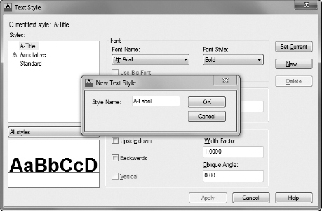
- Enter A-Title in the Style Name text box, as shown in Figure 8.4.
FIGURE 8.4 Setting the name for the new text style
By default, all new DWG files have the Standard text style as the current text style.
The New Text Style dialog box closes and, in the Text Style dialog box, A-Title appears highlighted in the Styles list.
You've created a new text style named A-Title. It has settings identical to those of the Standard text style, and it's now the current text style. Next, you'll change some of the settings for this new style.
- Move down to the Font group, and click the Font Name drop-down list to open it.
A font is a collection of text characters and symbols that all share a characteristic style of design and proportion.
A list of fonts appears; the number of choices depends on what software is installed on your computer. AutoCAD can use both its native SHX (Compiled Shape) font files and Windows TTF (TrueType font) files.
 Scroll through the list until you find Arial, and then click it.
Notice the TT icon to the left of the font name. This icon tells you that Arial font is a TrueType (.ttf) font.
The list closes and, in the Font Name text box, the Arial font replaces the txt.shx font that was previously there. In the Preview area in the lower-left corner, a sample of the Arial font replaces that of the txt.shx font.
- Because view labels are generally emphasized, change the Font Style from Regular to Bold.
The preview in the lower-left corner updates to reflect the Font Style change.
- Press the Tab key a few times to move to the next text box. The Height setting is highlighted at the default of 0′-0″ (0).
- Enter 12 (350), and then press Tab again. A height of 1′-0″ replaces the initial imperial measurement of 12″.
Because the A-Title text style will be used for headings and titles, it will use a plotted height of
 (7 mm). Once again, the model space height for this text was derived by multiplying the plotted height of (7 mm) by the drawing scale factor 48 (50). Your Text Style dialog box should look like Figure 8.5.
You won't need to change any of the other parameters that define the new text style. They can all stay at their default settings.
- Click the Apply button at the bottom of the dialog box.
The A-Title text style is saved with the current drawing and becomes the current text style. The current text style appears in the Text Style drop-down list in the Text panel, as shown in Figure 8.6.
- Click Close to exit the Text Style dialog box.
- Save your drawing as I08-02-TitleStyle.dwg (M08-02-TitleStyle.dwg).
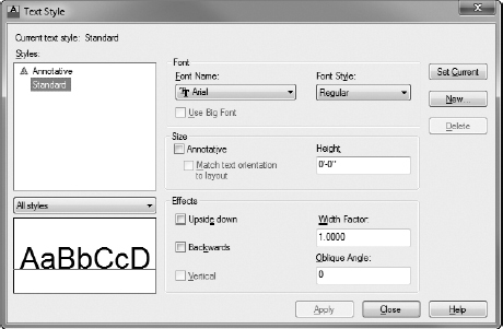
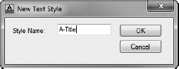
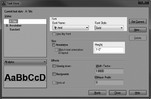
FIGURE 8.5 The Text Style dialog box after setting up the Title style
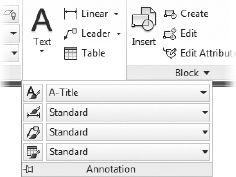
FIGURE 8.6 The Text Style drop-down list after setting A-Title as the current style
When you define a new text style, you first name the new style. This has the effect of making a copy of the current text style settings, giving them the new name, and making the new text style current. You then change the settings for this new style and save the changes by clicking Apply.
The current text style is similar to the current layer. All text created while a text style is current will follow the parameters or settings of that text style.
Of the many fonts available in AutoCAD, you'll use only a few for your drawings. Some are set up for foreign languages or mapping symbols. Others would appear out of place on architectural or technical drawings but might be just right for an advertising brochure or a flyer. Later in this chapter, you'll have a chance to experiment with the available fonts.
AutoCAD text styles can use either the AutoCAD SHX (Compiled Shape) font files or the Windows TTF (TrueType font) files on your system. The SHX fonts are older files that were originally designed for use with pen plotters, which required the pen tip to follow a precise vector. When you zoom in to an AutoCAD SHX font or print it large on a drawing, the straight line segments that compose it become apparent. Two more fonts in the Roman font family—romant (triplex) and romanc (complex)—have multiple, closely set lines and allow for larger text to be created while minimizing this straight-line effect.
TrueType fonts are mathematical representations of vector formats and are common in most Windows applications. Many fonts are available, and you can use them with no loss of crispness, regardless of the size of the font or the zoom factor in the drawing.
Until recently, the use of TTF fonts over the AutoCAD-specific SHX fonts would dramatically affect system performance. With performance the paramount concern, SHX fonts became the de facto standard. Recent advancements have made the performance differences between the two negligible. In fact, the default acad.dwt drawing template from Autodesk has used the TTF font Arial over the former SHX font for the last several releases of AutoCAD. The use of TTF fonts is also preferred over SHX fonts for the purposes of electronic archiving; SHX fonts cannot be searched or indexed by Windows. To follow this trend and ensure compatibility, this book also utilizes the TTF Arial font over the older SHX fonts for annotating your cabin.
Refer to Figure 8.3 for a moment, and note that the Standard text style has a height of 0′-0″ (0). When the current text style has a height set to 0, you're prompted to enter a height each time you begin to place single-line text in the drawing. The default height for the A-Title text style will scale to ![]() (or 0.25 for decimal units and 7 for metric) when plotted. Multiline text will use the default height of
(or 0.25 for decimal units and 7 for metric) when plotted. Multiline text will use the default height of ![]() (7 mm) unless you change it.
(7 mm) unless you change it.
Placing Titles of Views in the Drawing
After creating a text style, you're ready to begin adding text to your drawing. Before you can do that, you must first choose which type of text you would like to use: single-line or multiline text. The differences between them were discussed at the start of this chapter. To summarize, however, single-line text is limited to one line, and multiline text can support multiple lines of text for things like paragraphs.
Because the view title needs only a single line of text, you'll use the Single Line Text tool in this exercise. So that you can experience the differences for yourself, an exercise later will utilize multiline text instead of the single-line text you'll use here.
- Make sure I08-02-TitleStyle.dwg (M08-02-TitleStyle.dwg) is open.
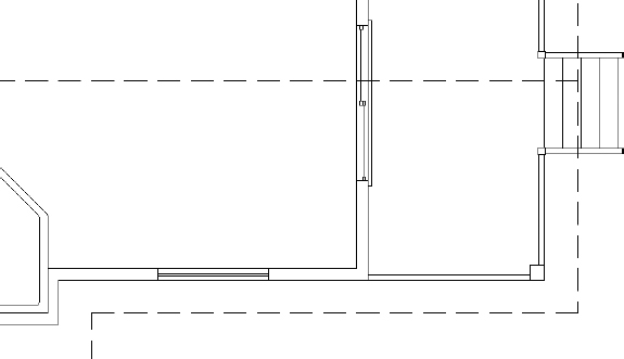
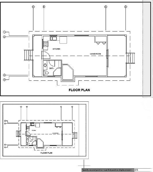
- Use the Zoom and Pan tools to make your view similar to the one shown in Figure 8.7.
FIGURE 8.7 Preparing to create title text by setting your view
- Set up your osnaps and status bar options so that Polar Tracking and Object Snap are on and the Endpoint and Midpoint osnaps are running.
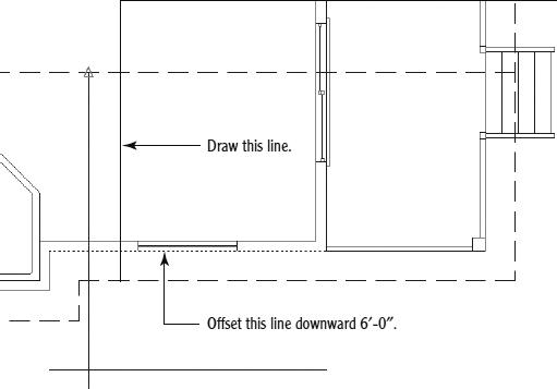
- Drop a line from the midpoint of the ridgeline in the floor plan straight down to a point near the bottom of the screen.
- Offset the horizontal, outside wall line to the right of the pop-out in the floor plan down 6′ (1830 mm), as shown in Figure 8.8.
FIGURE 8.8 The new lines created after offsetting the ridgeline and the pop-out
- Verify that the Text Style drop-down menu found on the Annotate tab Text panel matches Figure 8.9 and has the A-Title text style set as current.
FIGURE 8.9 Verifying the current text style (A-Title) and starting the Single Line Text (TEXT) command
The current text style, A-Title in this example, determines the text style used by any new text objects you create.
Click the down-arrow below the Multiline text button in the Text panel, and click the Single Line Text button in the fly-out menu, or enter DT
to start the TEXT command—the command used for single-line text.The command line reports information about the current text style: Current text style: “A-Title” Text height: 1′-0″ (350) Annotative: No. The window then prompts you: Specify start point of text or [Justify/Style]:.
You will use the Justify option to change the justification to Middle.
- Choose the Justify option by picking it on the command line or by pressing the down-arrow on the keyboard until Justify is selected at the cursor prompt and then press .
The justification point for the text functions like the insertion point for blocks.
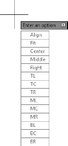
All the possible justification points appear in the prompt, as shown in Figure 8.10.
FIGURE 8.10 The single-line text justification options
- Enter C to choose Center as the justification.
- Use the Shift+right-click menu to choose the Intersection osnap, and pick the intersection of the guideline and the offset line.
- At the Specify rotation angle of text: prompt, press to accept the default angle of 0°, or enter 0 if 0° is not the default.
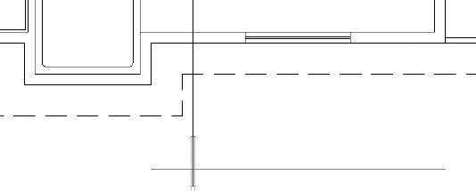
A flashing I-shaped cursor superimposed over a narrow box appears at the intersection (see Figure 8.11).
FIGURE 8.11 The text cursor sits on the guidelines.
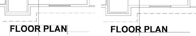
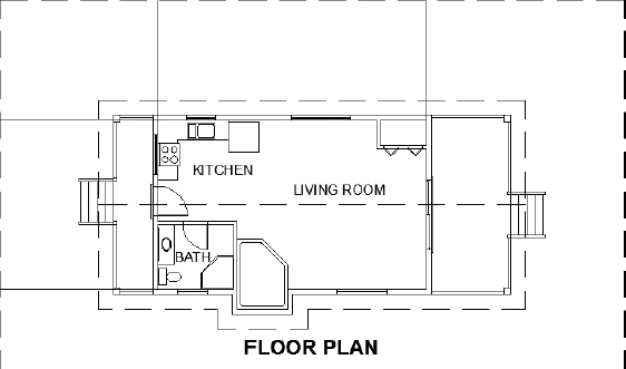
- With Caps Lock on, enter FLOOR PLAN.
The text is centered at the intersection as you enter it, and the cursor moves down to allow you to enter another line (see the left image in Figure 8.12).
FIGURE 8.12 The first line of text is entered (left) and placed (right).
- Press again to end the TEXT command.
The text is centered relative to the vertical guideline and sits on the offset line (see the right image of Figure 8.12).
- Erase the offset line and the vertical guideline. Your drawing will look like Figure 8.13.
- Save your drawing as I08-03-ViewTitle.dwg (M08-03-ViewTitle.dwg).

You specified a location for the text in two steps: first, you set the justification point of each line of text to be centered horizontally; second, you used the Intersection osnap to position the justification point at the intersection of the two guidelines. I'll discuss justification in more depth a little later in this chapter.
Next you'll use a similar procedure to begin adding room labels to the interior of your cabin.
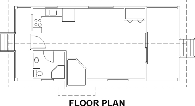
FIGURE 8.13 The drawing with the title complete
Using Annotative Text
You just finished using the Single Line Text tool in conjunction with the Standard text style A-Title to label your floor plan. Before you could create the A-Title text style, you had to use Table 8.1 to manually calculate the correct model space text height. Standard text styles, which require you to manually calculate the Height parameter, work great if you need to display your drawing at only a single scale.
Most plan sets include a combination of overall plan sheets, layout plan sheets, enlarged view sheets, and so on, so you'll probably need to establish a way to address annotation for each scale. Users who annotate their drawings in model space have traditionally solved this dilemma by creating separate text layers for each scale. Although this method works, it increases the possibility of errors because you're copying text and must remember to update each copy as revisions happen.
Another way to approach the dilemma of multiple scales, which also simplifies calculating the correct height for model space text, is the use of annotative text. Rather than calculating the correct model space height, by using annotative text you'll simply specify at what height you would like the text to plot. Using the Annotative Scaling features, AutoCAD will use the annotation scale to determine the correct height for your text.
Likewise, because annotative text objects can have multiple annotation scales assigned to them, annotative text also helps solve the dilemma of managing annotation at multiple scales. Assigning multiple annotation scales to a single piece of text allows you to display and position that one text entity at multiple scales. In other words, annotative text helps you reduce potential annotation errors by allowing you to manage one text entity, not one text entity for each scale.
Defining an Annotative Text Style
To get started with annotative text, you must first create an Annotative text style. Creating Annotative text styles is incredibly similar to creating Standard text styles. The biggest difference is that you will specify a Paper Space Height setting instead of the more generic Height parameter used with Standard text styles.
- Make sure I08-03-ViewTitle.dwg (M08-03-ViewTitle.dwg) is open.
- Start the STYLE command by entering ST at the command line or by choosing Manage Text Styles from the Text Style drop-down list found on the Annotate tab Text panel.
The Text Style dialog box opens, where you will begin defining a new Annotative text style.
- Select the A-Title style from the list on the left side of the Text Style dialog box, and click the New button.
The New Text Style dialog box opens, prompting you for a name for your new text style.
- Enter A-Label as the name, and click OK to return to the Text Style dialog box (see Figure 8.14).
FIGURE 8.14 Setting the name for the new text style
A new text style called A-Label is created and is now the current text style. Its font, height, and other settings are copied from the A-Title text style. Now you'll make changes to these settings to define the A-Label text style.
- Leave Arial as the Font Name, and change Font Style from Bold to Regular.
The list closes, and Regular appears as the chosen Font Style.
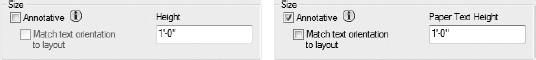
- Under the Size group within the Text Style dialog box, click the Annotative check box, as shown in Figure 8.15, but leave the Match Text Orientation To Layout box unchecked.
FIGURE 8.15 The Size group inside the Text Style dialog box with the Annotative option unchecked (left) and checked (right)
Notice how the Height parameter changes from Height to Paper Space Height.
- Enter
 (3.5) for the Paper Text Height.
If you press
 after entering the height, the new style is automatically applied, meaning that it is saved and made the current text style. Don't do this if you need to change other settings for the style.
The Text Style dialog box should look like Figure 8.16. Notice the small icon next to the A-Label text style you just created. This icon distinguishes Annotative text styles from non-Annotative, or Standard, text styles in the Text Style dialog box, and it is used throughout the software to refer to the annotative tools inside AutoCAD.
FIGURE 8.16 The Text Style dialog box after setting up the A-Label style
- Click Apply, and then click Close.
- Save your drawing as I08-04-AnnotativeStyle.dwg (M08-04-AnnotativeStyle.dwg).
![]() WARNING Depending on the drawing's precision, the Paper Text Height may round to 4 mm after you enter 3.5 mm. Despite rounding to 4 mm, AutoCAD will still create text with a height of 3.5 mm as entered in the Text Style dialog box. To verify, use the UNITS command to change the Length Precision property to 0.0.
WARNING Depending on the drawing's precision, the Paper Text Height may round to 4 mm after you enter 3.5 mm. Despite rounding to 4 mm, AutoCAD will still create text with a height of 3.5 mm as entered in the Text Style dialog box. To verify, use the UNITS command to change the Length Precision property to 0.0.
Now that you have an Annotative text style, you can start creating annotative text.
Placing Room Labels in the Floor Plan
To label the rooms inside your cabin, you'll use the Annotative A-Label text style you just created. Using Annotative text styles is very similar to using Standard text styles to create text, although you will need to ensure that the Annotative settings are correctly set so that the text you create will be scaled correctly. The following exercise will walk you through how to create annotative single-line text entities:
- Make sure I08-04-AnnotativeStyle.dwg (M08-04-AnnotativeStyle.dwg) is open.
- Click the Ortho Mode, Polar Tracking, and Object Snap buttons on the status bar to turn off these features.
 Click the Annotation Scale button found on the status bar, and change the scale to
 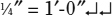 , as shown in Figure 8.17.
 TIP It's important to set the annotation scale before you create any annotative text objects because AutoCAD will use this as the default scale for the text objects you create. The current annotation scale is always displayed next to the Annotation Scale icon on the status bar. With this in mind, it's a good idea to get into the habit of glancing at the status bar to check this setting before creating annotative objects such as text.
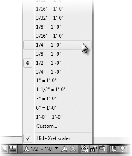
- Verify that the A-Label text style is current by expanding the Text Style drop-down list on the Annotate tab Text panel to display a list of all the text styles in the drawing.
FIGURE 8.17 Changing the annotation scale from the status bar
If necessary, click A-Label, as shown in Figure 8.18, to make Label the current style.
FIGURE 8.18 Selecting a new, current text style in the Text panel
- Start the TEXT command to begin creating the room labels.
- Pick a point in the living room between the refrigerator and the closet.
- Press at the rotation prompt. The text cursor appears at the point you picked.
VIEW TITLES HIGHLIGHTING AFTER STARING THE TEXT COMMAND?
The FLOOR PLAN view title text may become highlighted after starting the TEXT command. This happens whenever you start the TEXT command for the second time within any single drawing session—that is, when you haven't closed or otherwise reopened the current drawing since you last created text.
Starting the TEXT command for the second time will highlight the last text string you created. Pressing
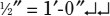
with this text highlighted at the Specify start point of text or [Justify/Style]: prompt will continue that string by creating a second string directly below it. This same behavior is seen later in this exercise as each room name is stacked on individual lines of text. - With Caps Lock on, enter KITCHEN LIVING ROOM BATH.
The TEXT command ends. You have three lines of text in the kitchen and living room area (see Figure 8.19).
FIGURE 8.19 The three room labels placed in the cabin
- Move your cursor over one of the text objects you just created.
Notice that the same Annotative icon used in the Text Style dialog box appears in the upper-right quadrant of the cursor to identify quickly that the object (a piece of text in this case) is Annotative.
- Save your drawing as I08-05-RoomLabels.dwg (M08-05-RoomLabels.dwg).

For this text, you used the default Left justification, and each line of text was positioned directly below the previous line at a spacing set by AutoCAD. In many cases, it's more efficient to enter a list of words or phrases first and then to move the text to its appropriate location. That's what you're doing for this text. When you know the location of the insertion point for the next line, you can click that point instead of pressing ![]() at the end of the current line. This starts the next line of text at the selected location.
at the end of the current line. This starts the next line of text at the selected location.
Moving Text and Working with Annotation Scales
Like most objects in AutoCAD, text can be moved by using the MOVE command or by using the grips associated with a given object. In most cases, there is no difference between using the MOVE command and using the grips to do what is known as a grip edit. Annotative text objects are an exception to this rule.
Using the grips associated with a piece of annotative text moves that piece of text only for the current Annotation Scale. At other scales, that same piece of text will remain in its previous location. You'll get to explore the difference between the two as you begin positioning the room labels in your cabin. Figure 8.20 shows how the text will look after it is moved into position.
- Make sure I08-05-RoomLabels.dwg (M08-05-RoomLabels.dwg) is open.

Next to the annotation scale in the status bar, make sure the Annotation Visibility (left) and Automatically Add Scales (right) buttons are in the On position.
In the case of Annotation Visibility, the On position is represented by a yellow lightbulb, and for Automatically Add Scales, a yellow lightning bolt is used.
- Change the annotation scale to
 .
.
The KITCHEN, LIVING ROOM, and BATH text size changes to reflect the newly selected annotation scale.
- Select the BATH text, and start the MOVE command found on the Home tab Modify panel.
- Move the BATH text between the bathroom cabinet and shower, as shown in Figure 8.20.
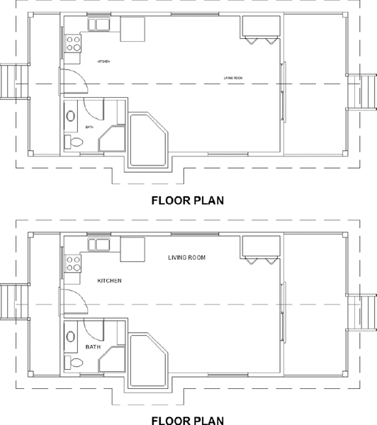
FIGURE 8.20 The LIVING ROOM, KITCHEN, and BATH text moved to their proper positions
- Repeat the MOVE command by pressing , moving the KITCHEN text to the position shown in Figure 8.20.
- Click the LIVING ROOM text. One grip appears at the justification point.
- Click the grip to activate it. The LIVING ROOM text is attached to the cursor and moves with it (see the top of Figure 8.21).
The STRETCH command automatically starts. Because text can't be stretched, the STRETCH command functions like the MOVE command.
- Move the cursor just above the roof centerline near the middle of the living room, and then click to place text at its new location.
- Press Esc to deselect the text and remove the grip.
- From the status bar, change the annotation scale back to .
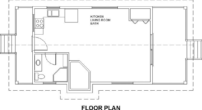
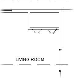
FIGURE 8.21 Room label locations at an annotation scale of
 (top) and
  (bottom)
The text size for each of the room labels gets larger, and the location for the LIVING ROOM text reverts to its original location, as shown at the bottom of Figure 8.21.
- Save your drawing as I08-06-MovingText.dwg (M08-06-MovingText.dwg).
An annotative object displays at the scale assigned to it. When you created the room labels, the annotation scale was set to ![]() , and so it was the scale AutoCAD used to size room labels correctly. At that point, your room labels were set up to display only at a scale of
, and so it was the scale AutoCAD used to size room labels correctly. At that point, your room labels were set up to display only at a scale of ![]() .
.
At the start of this exercise, you verified that the Add Annotation Scales button was turned on and then changed the annotation scale from ![]() to
to ![]() . In doing that, you added the
. In doing that, you added the ![]() scale to each of the three annotative objects in your drawing. Your room labels were then set up to display at both scales.
scale to each of the three annotative objects in your drawing. Your room labels were then set up to display at both scales.
When plans are being prepared at different scales, it's often necessary to place annotation objects such as text in different locations for some or all of the scales. This is done to avoid conflicts with other objects in the drawing and to make plans as readable as possible. This is the reason annotative objects allow you to specify multiple insertion points for each annotation scale assigned to an object. Likewise, this is where moving annotative objects by using grips differs from using the MOVE command.
As you saw with the KITCHEN and BATH text, the MOVE command changes the location for the entire text object, including its multiple annotation scales. On the other hand, using grips to move an annotative object moves only the object for the current annotation scale. As illustrated with the LIVING ROOM text, you used grips to move its location for the ![]() scale, but the original location was retained for the
scale, but the original location was retained for the ![]() scale.
scale.
Synchronizing Annotative Text Scale Positions
Use the following procedure to move the ![]() LIVING ROOM text to the same location as the
LIVING ROOM text to the same location as the ![]() LIVING ROOM text:
LIVING ROOM text:
- Make sure I08-06-MovingText.dwg (M08-06-MovingText.dwg) is open.
- Change the annotation scale back to by using the Annotation Scale menu on the status bar.
The LIVING ROOM text moves to its correct location on the screen.
- Select the LIVING ROOM text.
A blue grip appears at the insertion point of the
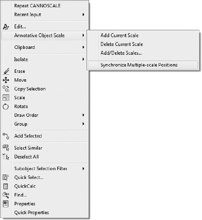
text, and the location of the text is shown ghosted (see Figure 8.22). - With the LIVING ROOM text still selected, right-click and choose Annotative Object Scale Synchronize Multiple-Scale Positions from the contextual menu shown in Figure 8.23.
FIGURE 8.22 Selected LIVING ROOM text displaying its multiple annotation scales
FIGURE 8.23 Choosing the Synchronize Multiple-Scale Positions option from the contextual menu
- Change the annotation scale to by using the Annotation Scale menu on the status bar.
- Using the Synchronize Multiple-Scale Positions tool, move the
 LIVING ROOM text so that it and the text share the same insertion point (see Figure 8.24).
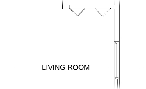
FIGURE 8.24 Location of the
(1:50) LIVING ROOM text after its location is synchronized - Save your drawing as I08-07-SyncPosition.dwg (M08-07-SyncPosition.dwg).
As you've seen, you have a couple of options when positioning text in a drawing. Annotative text is easier to size than standard text; however, using the grip at the insertion point will place the text at different locations for each scale, which may be an undesired result. When working with annotative text, the better choice is the MOVE command, although the Synchronize Multiple-Scale Positions option will help correct text placement if you erroneously use the insertion-point grip.
Even with the versatility that annotative text provides in the placement of text, occasionally the free space in a drawing will be so limited that a line and a piece of text will coincide. A common solution is to break the line where the text overlaps. To demonstrate how you might solve this type of issue in your own drawings, in the next section you'll need to erase part of a line where text intersects.
Breaking Lines with the Break Command
The BREAK command chops a line into two lines. When you're working with text that intersects a line, you'll usually want a gap between the lines after the break. The BREAK command provides this option as well as others. Follow these steps:
- Make sure I08-07-SyncPosition.dwg (M08-07-SyncPosition.dwg) is open.
- Enter UNDO M to set the undo mark so that you can return your drawing to the state it is in now.
- Select the LIVING ROOM text, and use the MOVE command to move it so that it rests on the ridgeline, as shown in Figure 8.25.
FIGURE 8.25 The selected text overlapping the ridgeline
 Turn off Object Snap, and start the BREAK command by selecting the Break button found inside the extended Modify panel on the Home tab.
You can also start the BREAK command by entering BR
.- Place the pickbox on the ridgeline just to the right of the text and click.
The line ghosts, and the cursor changes to the crosshair cursor. You just selected the line to break and picked one of the break points.
- Put the crosshair cursor on the ridgeline just to the left of the text, and pick that point.
The line is broken around the text, and the BREAK command ends. As you can see in Figure 8.26, the text is easier to read now than it was when the line was running through it.
- You don't want to retain your drawing in its current state, so enter UNDO B to revert to the undo point that you set with the Mark option.
- Continue to the next exercise without saving changes.
Breaking Lines with the Trim Command
When selecting cutting edges to be used by the TRIM command, you almost always select a linear object, line, arc, or polyline. A lesser-known feature of the TRIM command is that text objects may also be used as cutting edges. The end result is much the same as when you used the BREAK command, but the TRIM command ensures that the gap between the line and text is equal on both sides.
- Continue using I08-07-SyncPosition.dwg (M08-07-SyncPosition.dwg).
- Enter UNDO M to set the undo mark so that you can return your drawing to the state that it is in now.
- Start the TRIM command from the Home tab Modify panel, or enter TR at the command line.
- When prompted to Select Cutting Edges, select the LIVING ROOM text and press .
- At the Select Object To Trim Or Shift-Select To Extend prompt, select a point along the ridgeline where the LIVING ROOM text overlaps it, as shown in Figure 8.27.
- Press to end the TRIM command.
FIGURE 8.26 The ridgeline is broken on either side of the text.
The ridgeline is trimmed along the LIVING ROOM text object, as shown in Figure 8.28.
- To reset the position of the LIVING ROOM text and undo trimming the ridgeline, enter UNDO B.
- Continue to the next exercise without saving changes.
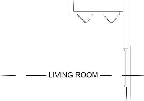
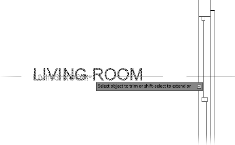
FIGURE 8.27 Breaking the ridgeline by using the TRIM command
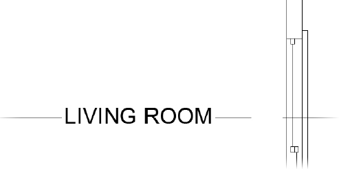
FIGURE 8.28 The ridgeline trimmed away
![]() TIP The multiline text objects have a mask feature that creates an envelope over and around the text, hiding the objects behind it. Unlike the breaking-lines approach, the masked objects reappear when you move the text. Masking is not supported for single-line text, but the Text Mask utility is available in the Express Tools. Express Tools are not included with AutoCAD LT.
TIP The multiline text objects have a mask feature that creates an envelope over and around the text, hiding the objects behind it. Unlike the breaking-lines approach, the masked objects reappear when you move the text. Masking is not supported for single-line text, but the Text Mask utility is available in the Express Tools. Express Tools are not included with AutoCAD LT.
Using Text in a Grid
AutoCAD provides a grid, which you worked with in Chapter 3, “Setting Up a Drawing.” The grid is a tool for visualizing the size of the drawing area and for drawing lines whose geometry conforms to the spacing of the dots or lines. Many floor plans have a separate structural grid created specifically for the project and made up of lines running vertically and horizontally through key structural components of the building. At one end of each gridline, a circle or a hexagon is placed, and a letter or number is centered in the shape to identify it. This kind of grid is usually reserved for large, complex drawings, but you'll put a small grid on the cabin floor plan to learn the basic method for laying one out:
- Make sure I08-07-SyncPosition.dwg (M08-07-SyncPosition.dwg) is open.
- Create a new layer called A-GRID. Assign it the color Red (1) and make it current.
- Offset the roofline polyline 10′ (3050 mm).
- Pan and zoom as necessary so that the cabin is centered onscreen and takes up only about 75 percent of the drawing area.
- Turn Object Snap on if it's off; set the Endpoint, Midpoint, and Perpendicular osnaps to be running; and then start the LINE command.
- Draw lines from the upper-left and upper-right inside corners of the walls up to the offset roofline.
- Draw lines from the upper-left and lower-left inside corners of the exterior walls to the vertical offset line on the left (see Figure 8.29).
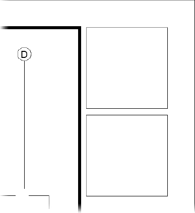
The gridlines need to be centered on the structural member they are identifying, in this case an 8×8 (204×204) column.
FIGURE 8.29 The first gridlines
A CLOSER LOOK AT THE BREAK COMMAND
Use your own judgment to determine how far from the text a line must be broken back. You have to strike a balance between making the text easy to read and keeping what the broken line represents clear.
Here are some options for the BREAK command:
- Ordinarily, when you select a line to be broken, the point where you pick the line becomes the beginning of the break. If the point where the break needs to start is at the intersection of two lines, you must select the line to be broken somewhere other than at a break point. Otherwise, AutoCAD won't know which line you want to break. In that case, after selecting the line to break, enter F. You'll be prompted to pick the first point of the break, and the command continues. Now that AutoCAD knows which line you want to break, you can use the Intersection osnap to pick the intersection of two lines.
- To break a line into two segments without leaving a gap, do the following:

1. Click the Break At Point button, which is on the expanded Modify panel. You might want to do this to place one part of a line on a different layer from the rest of the line.
2. Start the command.
3. Select the line to break.
4. Pick the point on the line where the break is to occur, using an osnap if necessary.
AutoCAD makes the break and ends the command.
- Ordinarily, when you select a line to be broken, the point where you pick the line becomes the beginning of the break. If the point where the break needs to start is at the intersection of two lines, you must select the line to be broken somewhere other than at a break point. Otherwise, AutoCAD won't know which line you want to break. In that case, after selecting the line to break, enter F
- Start the OFFSET command, enter E Y to set the Erase parameter, and then set the offset distance to 4″ (102 mm). Now when an object is offset, the original is erased.
- Offset each of the gridlines 4″ (102 mm) toward the inside of the cabin.
You may notice that the toilet will interfere with the new column in the lower-left corner of the cabin.
- Move the toilet up 4″ (102 mm) to add clearance and then adjust the size of the sink counter and mirror as well.
Now you need to draw gridlines for the posts at the corners of the decks.
- From the horizontal midpoint of the top-right and top-left deck posts, draw lines vertically to the offset roofline.
- Next, draw lines from the upper-left and lower-left deck posts horizontally to the offset roofline.
- This time add a jog to each column line so that their endpoints are not too close to the endpoints of the existing horizontal column lines (see Figure 8.30). You need to leave space for the column tag and don't want them to overlap.
FIGURE 8.30 The column lines for the deck posts
The column lines should not extend all the way to the cabin; there should be a gap to keep the drawing from getting congested and confusing.
- Use the TRIM command to trim each of the column lines back to the roofline, as shown in Figure 8.31.
Use the F8 key to toggle Ortho mode on and off in order to keep the jogged lines straight.
 Start the LENGTHEN command by clicking the Lengthen tool found on the extended Modify panel of the Home tab. Alternatively, you can enter LEN at the command line.
FIGURE 8.31 The column lines are trimmed back to the newly offset rooflines.
TIP Multifunctional grips provide in-context access to many commands such as the Lengthen tool. Hovering over the endpoint of a line, arc, or polyline will reveal a menu with the option of lengthening each of these objects. Because this version of the Lengthen tool relies on Dynamic Input, it does not provide access to options such as the Delta option used in the next step, and it is therefore not the best tool for this exercise.- Enter DE to choose the Delta option at the Select an object or [DElta/Percent/Total/DYnamic] prompt.
The Delta option will let you change the length of a line, arc, or polyline by a specified distance. In this case, you want to subtract 6″ (150 mm) from the total length of each gridline.
- To subtract 6″ (150 mm) from each gridline, enter -6 (-150) at the Enter delta length or [Angle] <0′-0″>: prompt.
- Select each of the eight column lines near where it intersects with the offset roofline.
Upon selecting each column line, its length will be shortened by 6″ (150 mm).
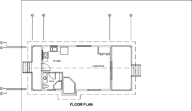
- Erase the roofline offset you created in step 3, and then zoom out to a view that includes the floor plan and the gridlines (see Figure 8.32).
FIGURE 8.32 The cabin with the completed gridlines drawn and the offset roofline deleted
When several osnaps are running, the marker for only one (and not necessarily the correct one) appears at a time. By pressing the Tab key, you can cycle through all the running osnaps for every object your cursor is over or near.
- Save your drawing as I08-08-GridLine.dwg (M08-08-GridLine.dwg).
This completes the gridlines. To finish the grid, you need to add a circle with a letter or a number in it to the left or upper end of the lines. You'll use letters across the top and numbers running down the side:
- Make sure I08-08-GridLine.dwg (M08-08-GridLine.dwg) is open.
 From the Home tab Draw panel, expand the Circle fly-out menu and click 2-Point.
The 2-Point option draws a circle defined by selecting two opposite points of the circle's diameter.
- At the Specify first end point of circle's diameter: prompt, pick the upper end of the leftmost vertical gridline.
- Turn Ortho mode on, move the cursor directly above the last point, and enter 12″ (305) at the Specify second end point of circle's diameter: prompt.
This places a circle 12″ (305 mm) in diameter at the top of the gridline (see the left image of Figure 8.33). Note that you can enable drawing modes with a command active.
- Turn Ortho mode off and click the KITCHEN text. A grip appears.
- Click the grip. Type C for copy and then press .
- Activate the Center osnap, and click the circle on the grid.
The KITCHEN text appears on the circle, with the lower-left corner of the text at the center of the circle (see the right image of Figure 8.33).
FIGURE 8.33 The circle on the gridline (left) and the KITCHEN text copied to the circle (right)
- Press Esc twice, once to end the Stretch function and again to clear the grip.
- Click the copy of the KITCHEN text that is now on the grid, right-click to bring up the context menu, and then click Properties to open the Properties palette.
Text appears on the drop-down list at the top, telling you that you've selected a text object.
- Use the Properties palette to make the following changes to the KITCHEN text:
- Under General, change Layer to A-GRID (see Figure 8.34).
- Under Text, change Contents from KITCHEN to A.
- Change the Justify setting from Left to Middle Center.
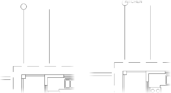
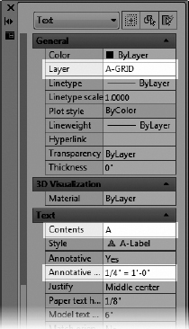
FIGURE 8.34 Modifying the KITCHEN text by using the Properties palette
![]() TIP This exercise might seem like a roundabout way to generate letters the grid symbols, but it is meant to show you how easy it is to use text from one part of the drawing for a completely different text purpose. It's a handy technique as long as you want to use a font that has been chosen for a previously defined text style. A faster way to do this is to use the Single Line Text tool. With the Justify setting set to Middle, use the Center osnap to place the text cursor at the center of the circle, and then enter A
TIP This exercise might seem like a roundabout way to generate letters the grid symbols, but it is meant to show you how easy it is to use text from one part of the drawing for a completely different text purpose. It's a handy technique as long as you want to use a font that has been chosen for a previously defined text style. A faster way to do this is to use the Single Line Text tool. With the Justify setting set to Middle, use the Center osnap to place the text cursor at the center of the circle, and then enter A![]()
![]() .
.
For each change, follow these steps in the Properties palette:
- Click the category in the left column that needs to change. If the setting is on a drop-down list, an arrow appears in the right column.
- Click the down-arrow to open the list. In the case of the KITCHEN text, just highlight it because there is no drop-down list.
- Click the new setting or enter it.
- When you've finished, close the Properties palette and press Esc to deselect the text.
- Save your drawing as I08-09-GridBubble.dwg (M08-09-GridBubble.dwg).
The KITCHEN text changes to the letter A, centered in the grid circle, and moves to the Grid layer (see Figure 8.35).
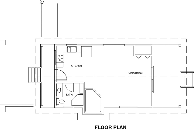
FIGURE 8.35 The grid circle with the letter A
You used the Center osnap on the KITCHEN text to position its justification point at the center of the circle. You then modified the justification point from the Left position (which is short for Base Left) to the Middle Center position. The Middle Center position is the middle of the line of text, horizontally and vertically. Thus, what you did had the effect of centering the text in the circle. You'll now look briefly at text justification.
Justifying Text
Each line of single-line text is an object. It has a justification point, which is similar to the insertion points on blocks. When drawing, you can use the Insert osnap to locate precisely the justification point of text (or the insertion point of blocks) and thereby control the text's position on the drawing. When you use the Single Line Text or TEXT command, the default justification point is the lower-left corner of the line of text. At the TEXT prompt (Specify start point of text or [Justify/Style]:), if you enter J![]() , you get the prompt Enter an option [Align/Fit/Center/Middle/Right/TL/TC/TR/ML/MC/MR/BL/BC/BR]:. These are your justification options.
, you get the prompt Enter an option [Align/Fit/Center/Middle/Right/TL/TC/TR/ML/MC/MR/BL/BC/BR]:. These are your justification options.
Figure 8.36 shows most of these options. The dots are in three columns—left, center, and right—and in four rows—top, middle, lower, and base. The names of the justification locations are based on these columns and rows. For example, you have TL for Top Left, MR for Middle Right, and so on. The third row down doesn't use the name Lower; it simply goes by Left, Center, and Right. Left is the default justification position, so it's not in the list of options. The Middle position sometimes coincides with the Middle Center position, but not always. For example, if a line of text has descenders—portions of lowercase letters that drop below the baseline, such as j and p—the Middle position drops below the Middle Center position. Finally, the lowest row, the Base row, sits just below the letters at the lowest point of any descenders.
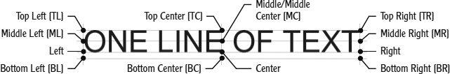
FIGURE 8.36 The justification points on a line of text
Finishing the Grid
To finish the grid, you need to copy the grid circle and its text to each gridline and then change the text:
- Make sure I08-09-GridBubble.dwg (M08-09-GridBubble.dwg) is open.
- Make sure Object Snap is turned on, and enable the Endpoint and Quadrant osnaps.
- Select both the letter A and the circle.
Grips appear: two for the text, one at the original justification point and one at the new justification point, one at the center of the circle, and one at each of the circle's quadrant points.
- Right-click, and choose Copy Selection from the context menu. Pick the upper endpoint of the grid with the A as the base point.
- Pick the top end of each vertical gridline.
- Right-click, and choose Enter to terminate the command (see Figure 8.37).
- Move back to the original grid circle, and select the grip on the right side of the circle to activate it.
- Right-click, choose Copy Selection from the context menu, and pick the right Quadrant of the circle as the base point.
FIGURE 8.37 The grid circle and letter are copied to the top of all three vertical lines.
- Copy the circle to the left endpoint for each of the horizontal gridlines.
- Press Esc to deselect the objects and remove the grips. Then, if necessary, use the STRETCH command to adjust the jogged lines and eliminate any overlap.
Now you'll use the DDEDIT command to change the text in each circle.
- Be sure Caps Lock is on, and then double-click the letter A in the second grid circle from the left in the top row.
The text now has a blue background to indicate that it is being edited.
- Enter B. The A changes to B.
- Click the A in the next circle to the right, and then enter C. The A changes to a C.
Editing text is one of the situations in which pressing the spacebar does not have the same effect as pressing
. - Repeat this process for the remaining five grid circle letters, changing them to D, 1, 2, 3, and 4.
- Press to end the Edit Text command.
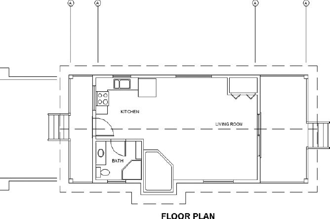
The letters and numbers are all in place, and the grid is complete (see Figure 8.38).
FIGURE 8.38 The completed grid
- Save this drawing as I08-10-CompleteGrid.dwg (M08-10-CompleteGrid.dwg).
Often, it's easier to copy existing text and modify it than to create new text, and grips are a handy way to copy text. Using the command (technically called TEDIT) is a quick way to modify the wording of short lines of text, meaning those that consist of a word or a few letters. The Properties palette is useful for changing all aspects of a line of text.
For the next exercise with text, you'll get a chance to set up some more new text styles, place text precisely, and use the DDEDIT command again to modify text content. You'll do all this while you develop a title block for your drawing.
Creating a Title Block and Border
The first step in creating a title block and border for the cabin drawing is deciding on a sheet size for printing the final drawing. Because many people have access to 11″×17″ (297×420) format printers, you'll use that sheet size. So if you print the drawing at a scale of ![]() (1:50), will the drawing fit on the sheet?
(1:50), will the drawing fit on the sheet?
To answer that question, you have to ask how big an area will fit on an 11″×17″ (A3, or 297 mm×420 mm) sheet at ![]() (1:50) scale. The answer is quite simple. Every inch (millimeter) on the sheet represents 48″ (50 mm) in the drawing (because 12″ divided by ¼ is 48″, and 50 mm divided by 1 is 50 mm). Therefore, you multiply each dimension of the sheet in inches (millimeters) by 48 (50). For this sheet, you multiply 11″×48 (297 mm×50) to get 528″ (14,850 mm), or 45′-4″ (see Figure 8.39). You multiply 17″×48 (420 mm×50) to get 816″ (21,000 mm), or 68′ (21 meters), as shown in Figure 8.39. So, the 11″×17″ (297 mm×420 mm) sheet represents a rectangle with dimensions of approximately 528″×816″ (14,850 mm×21,000 mm) at a scale of
(1:50) scale. The answer is quite simple. Every inch (millimeter) on the sheet represents 48″ (50 mm) in the drawing (because 12″ divided by ¼ is 48″, and 50 mm divided by 1 is 50 mm). Therefore, you multiply each dimension of the sheet in inches (millimeters) by 48 (50). For this sheet, you multiply 11″×48 (297 mm×50) to get 528″ (14,850 mm), or 45′-4″ (see Figure 8.39). You multiply 17″×48 (420 mm×50) to get 816″ (21,000 mm), or 68′ (21 meters), as shown in Figure 8.39. So, the 11″×17″ (297 mm×420 mm) sheet represents a rectangle with dimensions of approximately 528″×816″ (14,850 mm×21,000 mm) at a scale of ![]() (1:50), which is usually called quarter-inch scale.
(1:50), which is usually called quarter-inch scale.
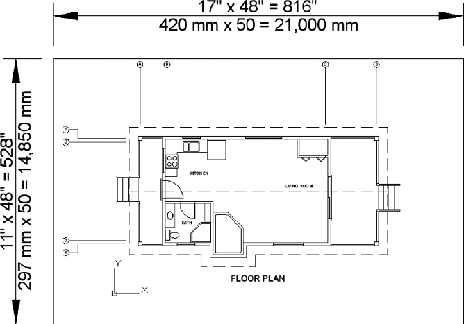
FIGURE 8.39 Approximating the viewable area for the ![]() (1:50) scale
(1:50) scale
Because most printers and plotters are not full-bleed devices, you'll need to factor in room for a margin around the outer edge of your sheet. Although the floor plan fits without any problems, you may need to adjust the column lines for them to fit into the printable area. Chapter 14 discusses layouts, and you will learn how to display the content of a single drawing at different scales—likely solving this issue. Even when you account for the unprintable area around the perimeter of the sheet, there should be plenty of room for your cabin drawing. This is the information you need to start creating the title block.
Drawing the Border
The border of the drawing will be set in from the edge of the sheet. Here are the steps:
- Make sure I08-10-CompleteGrid.dwg (M08-10-CompleteGrid.dwg) is open.
- Create a new layer called A-ANNO-TTLB. Assign the color Green (3), and make this layer current.
- Start the Rectangle (RECTANG) command (used in Chapter 4, “Developing Drawing Strategies: Part 1,” to make the doors).
- At the prompt, enter 0,0. Then enter 68′, 48′ (21000,14850).
This draws a rectangle that may extend off the top of the screen.
- Use Zoom Extents to zoom out until the entire rectangle is visible in the drawing area (see Figure 8.40).
FIGURE 8.40 Zooming out to include the entire rectangle
You need to fit the drawing into the rectangle as if you were fitting it on a sheet of paper. The easiest and safest way to do this is to move the rectangle over to enclose the drawing. You'll leave plenty of room for the elevations that you will draw in a later chapter.
- At the command line, click the rectangle to select it. Grips appear at the corners of the rectangle.
- Click the lower-left grip.
- Press the spacebar once to switch from Stretch mode to Move mode.
Once you activate a grip and the Stretch function begins, pressing the spacebar toggles through the other four commands in this order: Move, Rotate, Scale, Mirror.
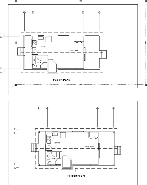
- Move the rectangle over the drawing (see the top of Figure 8.41).
FIGURE 8.41 Moving the rectangle with grips (top) and the results (bottom)
- When the rectangle is approximately in the position shown at the bottom of Figure 8.41, click.
- Press Esc to deselect the rectangle. The rectangle is positioned around the drawing and represents the edge of the sheet.
- You need a border set in from the edge. Offset the rectangle 2′ (650 mm) to the inside.
With a scale of
(1: 50), each 1′-0″ (50 mm) on the drawing will be represented by (1 mm) on the sheet. So, a 2′ (500 mm) offset distance will create an offset of ½″ (13 mm) on the printed sheet. - Double-click the inside rectangle to start the PEDIT command.
- Enter W 2 (50).
This command sets the width of the inside rectangle's segments to 2′ (50 mm).
- Move both rectangles to center the cabin.
- Use Zoom Extents, and then zoom out a little to create a view in which the drawing with its border nearly fills the screen (see Figure 8.42).
FIGURE 8.42 The drawing with its border
- Save this drawing as I08-11-BorderFrame.dwg (M08-11-BorderFrame.dwg).
The outer rectangle represents the edge of the sheet of paper, and the thicker, inner rectangle is the drawing's border.
Constructing a Title block
The title block is a box that contains general information about a drawing, such as the name of the project, the design company, and the date. It will be set up along the right edge of the border and will use the same special line, the polyline, that is created when the Rectangle (RECTANG) command is executed.
You first used the Rectangle (RECTANG) command in Chapter 4 for drawing the doors. At that time, I mentioned that rectangles created with this command consist of a polyline whose four segments are grouped as one object. In step 14 of the previous section, you saw that these segments could have varying widths.
These same principles will be applied as you construct the title block for your cabin project. You'll draw a series of rectangles that will eventually contain information about your project and drawing such as project name, drawing title, and drawing scale. Polylines, such as those created by the RECTANG command, include a width property. This ability to have a width property makes polylines especially useful in constructing title blocks. You'll use the RECTANG and PLINE commands to draw the various lines that make up the title block, and then you'll fill in the text:
- Make sure I08-11-BorderFrame.dwg (M08-11-BorderFrame.dwg) is open.
- With the entire title-block frame in view, start the STRETCH command found on the Home tab Modify panel.
- At the Select objects: prompt, create a crossing window selection around the inner-right edge, as shown at the top of Figure 8.43, and press .
- Pick any point in the drawing at the Specify base point prompt.
- With Ortho mode turned on, move your cursor to the left and use direct distance entry to specify a displacement of 6′-6″ (2050 mm), as shown at the bottom of Figure 8.43.
By reducing the inner frame's width, you now have enough room to include both project and drawing information along the right edge of your plan sheet. The rectangles and polylines you'll draw next will help provide structure to this data.
- Ensure that Object Snap and Object Snap Tracking are both enabled with Endpoint chosen as a running object snap.
FIGURE 8.43 crossing window selection around the inner-right title-block edge (top), and specifying the displacement distance (bottom)
- Zoom in to the upper-right corner of your title block, bringing both the inner and outer title-block frames into view.
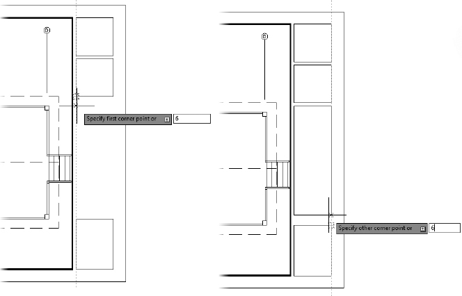
- Start the Rectangle (RECTANG) command, and use Object Snap Tracking to begin drawing a rectangle 6″ (150 mm) to the right of the inner title-block frame, as shown in Figure 8.44.
FIGURE 8.44 Using Object Snap Tracking to acquire the rectangle starting point
- Enter 72,-72 (1900,-1900) at the Specify other corner point prompt to complete the rectangle. The top rectangle shown in Figure 8.45 is drawn.
FIGURE 8.45 Accurately positioned 72″×72″ (1900 mm×1900 mm) title-block components
- Using the same process, acquire a point 6″ (150 mm) below the rectangle; create another 72″×72″ (1900 mm×1900 mm) rectangle, shown as the bottom rectangle in Figure 8.45.
- Repeat steps 8 and 9 to create a 72″×96″ (1900 mm×2440 mm) rectangle 6″ (150 mm) to the right of the lower-right title-block frame.
- Use Object Snap Tracking to compose the final rectangle 6″ (150 mm) below the top series of rectangles, and 6″ (150 mm) above the bottom rectangle, as shown in Figure 8.46).
FIGURE 8.46 Using Object Snap Tracking to acquire the first corner point (left) and second corner point (right)
 Use the Match Properties (MATCHPROP) command found on the Home tab Clipboard panel to assign the correct polyline width to each of the newly created rectangles.
- At the Select source object prompt, select the inner title-block frame that's currently bolder (thicker) than the other lines in your drawing.
- At the Select destination object(s) prompt, select each of the rectangles drawn during this exercise along the right edge of the title block by using the selection method of your choice. Press to exit the command.
Each of the object properties, such as layer, lineweight, and width, are synchronized between the source and destination objects (see Figure 8.47).
FIGURE 8.47 The completed rectangle stack along the right title-block edge
- Use the LINE command to subdivide the lower two rectangles along the right edge of your title block (see Figure 8.48).
FIGURE 8.48 The completed title-block frame
- Save this drawing as I08-12-CompleteFrame.dwg (M08-12-CompleteFrame.dwg).

MATCHING PROPERTIES WITH THE MATCH PROPERTIES COMMAND
The Match Properties (MATCHPROP) command is an excellent way to easily synchronize the properties between any two AutoCAD objects. Although the source and destination objects do not need to be of the same object type (text to text, lines to lines, and so forth), it is important to recognize that only shared properties will be matched. For example, it's possible to match the inner title-block (polyline) frame with a piece of text; however, Global Width, a property exclusive to polylines, would not be applied to any text entities.
A common use of the Match Properties (MATCHPROP) command is to coordinate the Layer property of two or more objects. While this can be an effective approach, it's important to recognize that all shared properties will be matched. If Layer is the only property you need to match, the Match (LAYMCH) command found on the Home tab ![]() Layers panel can be a great alternative to the Match Properties (MATCHPROP) command.
Layers panel can be a great alternative to the Match Properties (MATCHPROP) command.
Putting Text in the Title Block
The title block has several boxes that will each contain distinct pieces of information. The two top boxes will contain information related to your company, including its logo and contact information. Below these two uppermost boxes, the largest box will contain the name of the project and the current drawing's title. Finally, the lowest box will contain information specific to this drawing: drawing scale, submittal date, creator's initials (yours), and drawing or sheet number. Most title-block layouts contain this information and more, depending on the complexity of the job.
You need to put labels in some of the boxes to identify what information will appear there. For this, you need to set up a new text style:
- Make sure I08-12-CompleteFrame.dwg (M08-12-CompleteFrame.dwg) is open.
- Create a new layer named A-ANNO-TTLB-TEXT. Assign it the color Cyan (4), and make it current.
- On the Text panel under the Ribbon's Annotate tab, expand the Text Style drop-down list, and click Manage Text Styles.
- The A-Label text style should still be current. If not, select it.
- Click New, enter A-Ttlb, and then click OK.
- Leave the font set to Arial, but deselect the Annotative check box and change the height to 6″ (175).
If you press
after changing the height, the Apply button turns gray and is unselectable. Pressing at this point has the same effect as clicking the Apply button. - Assuming the Text Style dialog box looks like Figure 8.49, click Apply and then Close. A-Ttlb is the current text style.
FIGURE 8.49 Using the A-Label text style as a template for the A-Ttlb text style
- Be sure Caps Lock is on, and start the Single Line Text or TEXT command.
- Enter J at the command line to open the text justification options, and then TL to specify a Top-Left justification.
- Use the Endpoint osnap to pick the upper-left corner of the lowest box.
- Press at the rotation prompt. Enter SCALE:.
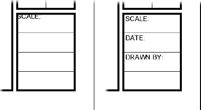
The word SCALE: appears in the lowest box (see the left of Figure 8.50). Don't worry about the box's boundary overlapping the SCALE text, as you'll fix this in a moment.
FIGURE 8.50 One line of text placed (left) and the completed title-block labels (right)
- Use the COPY command to copy this text to the two boxes below it, using the endpoint of the horizontal lines above each of the boxes as the base and displacement points.
- Double-click the topmost-copied text to start the TEDIT command.
- Enter DATE: and press . Pick the lower copy of text. The blue editing background returns.
- Enter DRAWN BY: and press . Press to end the TEDIT command.
- Position each of the labels by using the MOVE command.
The closer you zoom in, the more precisely you'll be able to fine-tune the location of the text. You'll need to zoom out to check how it looks.
- Pick any point in the drawing as a base point, and enter @3,-3 (@75,-75) for the second point to move the labels into place (see the right image of Figure 8.50).
- Save this drawing as I08-13-DrawingLabels.dwg (M08-13-DrawingLabels.dwg).
Using the DDEDIT command is a quick way to change the wording of text and to correct spelling. You have to change one line at a time, but the command keeps running until you stop it. You can also change the Contents text box in the Properties palette.
The final area to work on in this lowest box is where the sheet number appears. This sheet number will serve as the unique identifier distinguishing it from all other drawing sheets in your plan set. For many of the same reasons page numbers in this and many other books are found in the corners of each page, sheet numbers are typically placed in a similar fashion. To aid in making the sheet number of each drawing in your plan set easy to read and identify, you'll place it in the lower-right corner and create a new text style.
- Make sure I08-13-DrawingLabels.dwg (M08-13-DrawingLabels.dwg) is open.
- Open the Text Style dialog box and click New.
- Turn off Caps Lock, enter A-Snbr, and click OK.
- Leave Arial as the font and change the height to 12 (350).
- Click Apply and then click Close. A-Snbr is now the current text style.
- Start the TEXT command and enter J.
- Enter MC to set the justification to the top center of the text.
- Right-click to select the Mid Between 2 Points osnap, and use the Endpoint osnap to pick the two endpoints along the top of the bottom-right box, as shown in Figure 8.51.
FIGURE 8.51 Positioning the text insertion point for the large box in the title block
- Press at the rotation prompt.
- Turn Caps Lock back on and then enter A-101.
The sheet number text is correctly positioned within its designated block (see Figure 8.52).
- With Polar Tracking on, use the MOVE command to move the text down and center it vertically in the box (see Figure 8.52).
Remember, when you select the text to move it, you have to pick each line because they are two separate objects.
- Save this drawing as I08-14-SheetNumber.dwg (M08-14-SheetNumber.dwg).
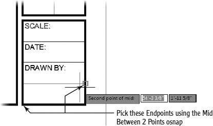
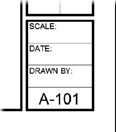
FIGURE 8.52 The sheet number text after being inserted
Now it's time for you to experiment, using the techniques you just learned to fill in the text for the other boxes.
The tallest of the four boxes composing your title block will be used to designate both the project name and sheet title. Like the other boxes, you'll designate each of these respective areas with a label.
- Make sure I08-14-SheetNumber.dwg (M08-14-SheetNumber.dwg) is open.
- Use the ZOOM command to bring the lower edge of the tallest box composing your title block into view.
- Set the A-Ttlb text style as current, and start the Single Line Text (TEXT) command.
- Set the justification to Top Left (TL), and choose the bottom-left endpoint as the start point.
- At the Specify rotation angle of text prompt, enter 90.
- Turn Caps Lock on if it's not already on, and then enter PROJECT:.
- Repeat the procedure outlined in steps 3–5 to create the SHEET TITLE: label in the area to the right of your PROJECT: label. Your drawing should look like the left image of Figure 8.53.
- Position the PROJECT: and SHEET TITLE: labels by using the MOVE command.
- Choose any point in your drawing as a base point, and then specify a displacement of @3,3 (@75,75).
Your drawing should match the right image of Figure 8.53.
FIGURE 8.53 Defining the PROJECT and SHEET TITLE areas (left) and positioning the labels (right)
- Using the A-Ttlb text style and a text justification of Bottom Right, fill in the following information:
- SCALE: (1:50)
- DATE: Enter any date
- DRAWN BY: Enter your initials
- SCALE:
- Use the MOVE command to position each of the title-block entries @-3,3 (@-75,75) to the left.
- Use the A-Snbr text style to fill in the project name, SUMMER CABIN, and sheet title, FIRST FLOOR PLAN, using the following parameters:
- Apply the Bottom Center (BC) text justification, and snap to the midpoint of the bottom line for each area.
- Specify a text rotation angle of 90°.
Your drawing should match Figure 8.54.
FIGURE 8.54 The completed lower title-block boxes
- Use the collection of Draw and Modify commands you've learned so far to create your own logo in the uppermost title-block box, or insert I08-Logo.dwg (M08-Logo.dwg) with these steps:
- Click Insert on the Insert tab Block panel to start the INSERT command.
- From the Insert dialog box, click Browse to locate the I08-Logo.dwg (M08-Logo.dwg) file. You can find this file in the Chapter 8 download found at www.sybex.com/go/autocad2013ner.
- If it's not already, check Specify On-Screen for Insertion Point, and uncheck Specify On-Screen for both Scale and Rotation. Click OK.
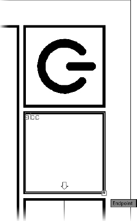
- Using the Endpoint osnap, pick the lower-left corner of the uppermost title-block box (see Figure 8.55).
- Click Insert on the Insert tab
- Save this drawing as I08-15-TtlbLogo.dwg (M08-15-TtlbLogo.dwg).
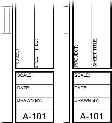
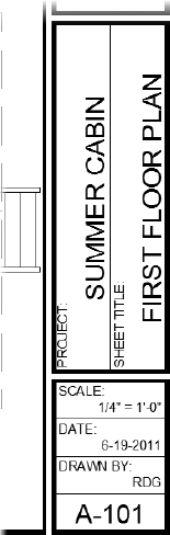
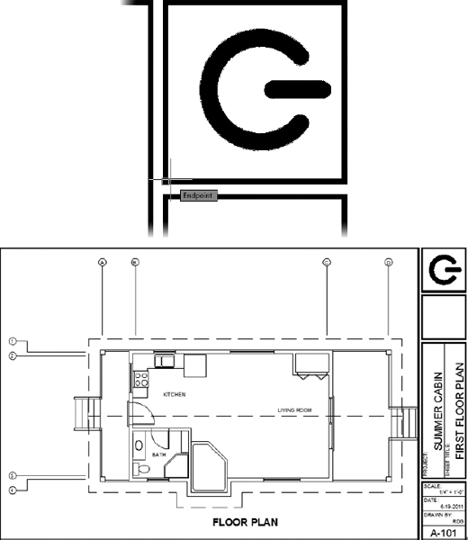
FIGURE 8.55 Inserting the title-block logo (top) and the completed title block (bottom)
Using Multiline Text
Multiline text (often referred to as Mtext) is more complex than single-line text. You can use it in the same way you used single-line text in this chapter, but it can do more. When you have several lines of text or when you need certain words within a line of text to appear differently from the adjacent words, multiline text is the best feature to use.
A paragraph of multiline text is a single entity. The text wraps around, and you can easily modify the length of a line after you place the text in the drawing. Within the multiline text entity, all text can be edited and behaves as if it were in a word processor. You can give a special word or letter of the text its own text style or color. Everything you learned about defining a new text style applies to multiline text because both kinds of text use the same text styles. Just as polylines become lines when exploded, multiline text is reduced to single-line text when exploded.
Use the EXPLODE command to turn multiline text into single-line text, to unblock objects in a block reference, and to convert a polyline into regular lines. Click the Explode button on the Modify panel to start the command.
Dimensions use multiline text, and any text that is imported into an AutoCAD drawing from a word processing document or text editor becomes multiline text in the drawing. In this section, you'll learn how to place a paragraph of multiline text in the cabin drawing and then modify it. In Chapter 12, “Dimensioning a Drawing,” you'll work with dimension text and text with leader lines, both of which use multiline text.
![]() TIP If you are using AutoCAD and have the Express Tools installed, the TXT2MTXT command (click Express Tools tab
TIP If you are using AutoCAD and have the Express Tools installed, the TXT2MTXT command (click Express Tools tab ![]() Text panel
Text panel ![]() Convert Text To Mtext) changes the selected Text objects into Mtext objects. When multiple lines of text are selected, they are converted into a single Mtext object. AutoCAD LT does not have the Express Tools available.
Convert Text To Mtext) changes the selected Text objects into Mtext objects. When multiple lines of text are selected, they are converted into a single Mtext object. AutoCAD LT does not have the Express Tools available.
Finishing the Title Block
In addition to the logo you inserted a moment ago, most title blocks will also contain basic company contact information. Because contact information usually spans several lines, multiline text is a perfect candidate to put the final touch on the composition of your title block.
- Make sure I08-15-TtlbLogo.dwg (M08-15-TtlbLogo.dwg) is open, and verify that the A-ANNO-TTLB-TEXT layer is set as current.
 Start the MTEXT command by clicking the Multiline Text button found on the Annotate tab Text panel. If the Multiline Text button isn't visible, click the down-arrow beneath the Single Line text button, and choose it from the list.
- Use the Endpoint osnap to choose the upper-left and lower-right corners of the title-block box directly below the logo box (see Figure 8.56).
FIGURE 8.56 Defining the multiline text box within the title block
- Enter the following information (see Figure 8.57):
- Company Name
- Street Address
- City, State, and Zip Code
- Telephone Number
- Website
- Click anywhere outside the text box, or click the Close Text Editor button on the contextual Text Editor tab Close panel. This closes the Multiline Text Editor and inserts your text into the drawing (see Figure 8.57).
Although the title-block box now includes the necessary contact information, it's likely not very legible. You may choose to do any number of things to make this text more legible: place greater emphasis on the company name or fix text-wrapping issues such as the City, State, Zip text seen in Figure 8.57. Thanks to the additional formatting options that multiline text provides, each of these modifications are easily applied:
- With your cursor placed over any character within your text box, double-click to open the contextual Text Editor Ribbon tab.
 Click the Justification button found on the contextual Text Editor tab Paragraph panel to apply a Middle Center text justification.
The text is centered both vertically and horizontally within the text box.
FIGURE 8.57 The company contact information placed within the title block before modifying formatting
- Use your cursor to highlight the Company Name text.
- Click the Bold button on the contextual Text Editor tab Formatting panel.
- Still inside the Multiline Text Editor, highlight the Street Address, City, State, and Zip Code, Telephone Number, and Website text.
- Reduce the text height for each of the selected components by entering 5 (125) within the Ribbon Combo Box - Text Height area of the Style panel on the contextual Text Editor tab.
- Ensure that your text is correctly positioned both horizontally and vertically by using the Middle Center justification option.
- On the contextual Text Editor tab Paragraph panel, expand the Justification button and choose Middle Center.
- Click anywhere outside the text box, or click the Close Text Editor button on the contextual Text Editor tab Close panel.
- Your title block should now resemble Figure 8.58. Save this drawing as I08-15-TtlbLogo.dwg (M08-15-TtlbLogo.dwg).


FIGURE 8.58 The completed title block
Using tools familiar to anyone who has used a word processor such as Microsoft Word, you were quickly able to increase the legibility of the text within the company-contact title-block box. This is just one example of how multiline text can prove itself invaluable when working with several lines of text at once.
Beyond the formatting tools explored in this first exercise involving multiline text, it's also important to note how text within a block of multiline text interacts with the other text within the same block. Changing the size of all but the company name from 6″ (175 mm) to 5″ (125 mm) also changed the spacing between each line of text. Had this been several strings of single-line text, the vertical relationship between each line of text would not have been retained.
Using Mtext for General Notes
The preceding exercise introduced you to several of the multiline text formatting options available. This expansive list of formatting options is especially helpful when managing large blocks of text such as the general notes typically found on many plan sheets. Expanding on this concept, the next several exercises will introduce you to many of these formatting options as you add general notes to your drawing.
Adding Columns to Mtext
To fit large blocks of text (like General Notes) onto a plan sheet, it's oftentimes necessary to divide the text into a series of columns. Complete the following steps to format the General Notes for your cabin drawing into multiple columns:
- Make sure I08-15-TtlbLogo.dwg (M08-15-TtlbLogo.dwg) is open.
 Click the Make Object's Layer Current button on the Layers panel.
- Click the FLOOR PLAN text to make the A-ANNO -TEXT layer current.
- If it isn't so already, change the current text style to A-Label from the Annotate tab Text panel.
- Zoom in to the blank area to the left of the title block, in the lower-left corner of the cabin drawing.
- Start the MTEXT command by clicking the Multiline Text button found on the Annotate tab Text panel, and press F3 to turn Object Snap off temporarily.
The command line displays the name of the current text style and height and prompts you to specify a first corner.
- Select a point near the left border, vertically in line with the roofline.
The prompt now reads Specify opposite corner or [Height/Justify/Line spacing/Rotation/Style/Width/Columns]:. These are all the options for the Multiline Text (MTEXT) command.
Unlike single-line text, Mtext uses a window to define the width of the text, rather than a point for the justification point.
- Drag open a window that fills the space between the left border and the left side of the pop-out.
This defines the line width for the multiline text (see Figure 8.59). Click to finish the window.
FIGURE 8.59 Making a multiline text window
Once you've defined the Multiline Text window, the Text Editor contextual Ribbon opens, providing options to configure and edit your Mtext entities. The Text Editor contextual Ribbon tab and its associated panels appear in the Ribbon.
The Style and Formatting panels allow you to see the current text style and its font and height, as shown in Figure 8.60. Just above the rectangle you defined, the Multiline Text Editor opens. This is where you'll enter the text.
FIGURE 8.60 The Style and Formatting panels on the Text Editor tab
- Enter the following text, using single spacing and pressing only at the end of the first line and at the end of each note. Lines that are longer than the window that you dragged out will wrap automatically:
GENERAL NOTES:
All work shall be in accordance with the 2000 Ed. Uniform Building Code and all local ordinances.
Roof can be built steeper for climates with heavy snowfall.
All windows to be double-paned.
- When you've finished, click a blank spot in the drawing area.
The text appears in the drawing (see the top of Figure 8.61). The window you specified was used only to define the line length. Its height doesn't control how far down the text extends; that is determined by how much text you enter.
Before you adjust the text to fit the area, you will have AutoCAD add numbering to the notes.
- Double-click anywhere on the new text to display the Multiline Text Editor and the Mtext panels.
- Move the cursor to the upper-left corner of the window containing the text and in front of the A in the first word (All) of the first note.
- Hold down the left mouse button, and drag to the right and down until all the remaining text is highlighted. Release the mouse button.
- Expand the Bullets And Numbering drop-down list in the contextual Text Editor tab Paragraph panel, and then choose Numbered from the cascading menu that pops up (see the middle of Figure 8.61).
 The note numbers appear. Click the Close Text Editor button on the Close panel.
- Select the text object, and open the Properties palette.
- Select the GENERAL NOTES: text, and in the Text rollout, highlight the Annotation Text Height input field and change the value from
 (5) to
  (4.5), and press .
AutoCAD redraws the GENERAL NOTES: text larger.
- Use the grip at the upper-right corner of the text to stretch the text box farther to the right.
The text reconfigures to fit the new constraints (see the bottom of Figure 8.61).
- Double-click the Mtext again. The Text Editor tab opens.
- Place your cursor after the ordinances text. Expand the Columns tool on the contextual Text Editor tab Insert panel, and choose Insert Column Break, as shown at the top of Figure 8.62. Your Mtext entity should look like the bottom of Figure 8.62 after inserting the column break.
FIGURE 8.61 Mtext in the drawing (top), adding the note numbers (middle), and the modified text (bottom)
Inserting a column break may insert an additional number in the GENERAL NOTES numbered list. If this happens, use the Backspace key to remove the additional line.
 Use the double-arrow to the far right of the Multiline Text Editor to position the new column closer to the first column on the left, as shown in Figure 8.63.
FIGURE 8.62 Using the Multiline Text Editor to insert a column break (top) and a new column (bottom)
 Use the diamond grip between the two columns to adjust the width for both columns so that they will fit along the lower edge of your drawing (see Figure 8.64).
FIGURE 8.63 Using the column slider to adjust multiline text column spacing
FIGURE 8.64 Resizing columns by using the Multiline Text Editor[
Your GENERAL NOTES text block should look like Figure 8.64.
- Complete the composition of your drawing sheet by using the MOVE and STRETCH commands.
- Move the GENERAL NOTES text to the lower-left corner of the title-block drawing area.
- After positioning the GENERAL NOTES text, move the title block down until the cabin fits neatly within the upper-border area and the notes are unobstructed.
- Use the STRETCH command to bring the vertical column grid-lines within the title-block drawing area.
Once complete, your drawing should resemble Figure 8.65.
FIGURE 8.65 The results of text and title-block adjustments
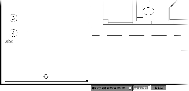
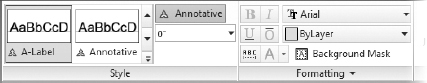
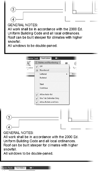
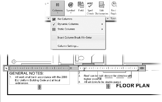
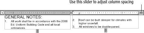
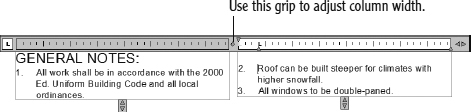
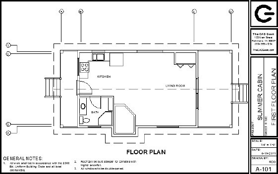
Formatting Individual Words within Mtext Entities
When TrueType fonts are used in AutoCAD drawings, any combination of formatting options may be applied. For example, you may choose to apply bold or italicized formatting to some portion of an Mtext entity. To see how to change individual words within the text, you'll underline and boldface the Uniform Building Code text:
- Zoom into and double-click the Mtext again.
- Use the same technique as you did earlier to highlight only the Uniform Building Code text.
 Click the Bold and Underline buttons on the Formatting panel.
This underlines the selected text and displays the bold feature.
 Click in the drawing area.
AutoCAD redraws the text with the changes (see Figure 8.66).
FIGURE 8.66 The Mtext with individual words modified
- Save this drawing as I08-16-GeneralNotes.dwg (M08-16-GeneralNotes.dwg).
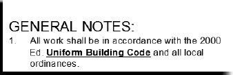
You just created an Mtext entity applying several formatting functions (bold and underline), and organized your GENERAL NOTES into columns. Organizing large blocks of text is commonly done in many plan sets. While you could create multiple Mtext entities to organize your text into columns, the column feature provides a much more comprehensive approach. By keeping everything contained inside a single Mtext entity, you'll ensure that features such as numbered lists work in a more predictable manner.
 In addition to columns, you also learned how to format individual words within an Mtext entity. You can italicize—or new to AutoCAD 2013, strike through individual words—and give them a different color or height from the rest of the Mtext by using the other tools on the Multiline Text panel. I encourage you to experiment with all these tools to become familiar with them. Another feature of Mtext is the ability to insert hyperlinks.
Adding a Hyperlink
You have the ability to add hyperlinks, links to web pages or files, to the body of an Mtext object. When a hyperlink to a URL exists, anyone with the drawing open can hold down the Ctrl button and click the link to open the associated page in their web browser. Hyperlinks can also point to local or network files, causing the file's associated application to open when they are clicked. Here is the procedure for adding a hyperlink:
- Make sure I08-16-GeneralNotes.dwg (M08-16-GeneralNotes.dwg) is open.
- Double-click the Mtext object.
- Highlight the Uniform Building Code text to indicate where you want the hyperlink to appear.
 On the contextual Text Editor tab Insert panel, click Field, or right-click and choose Insert Field from the context menu.
- In the Field Category section of the Field dialog box that opens, select Linked.
- Next, select Hyperlink from the Field Names section directly below the Field Category section.
- In the Text To Display field, enter Uniform Building Code.
This is the text that will appear in the tooltip when the cursor hovers over the hyperlink (see Figure 8.67).
FIGURE 8.67 The Field dialog box
- Click the Hyperlink button; then, in the Edit Hyperlink dialog box (see Figure 8.68), you can do any of the following:
- Enter the web page or filename and path in the Type The File Or Web Page Name box.
- Click the File button under Browse For to select a file that you will link to the text.
- Click the Web Page button under Browse For to navigate to the web page that you will link to the text.
FIGURE 8.68 The Edit Hyperlink dialog box
- Ensure that Existing File Or Web Page is selected on the right side of the dialog box, and then enter http://www.iccsafe.org into the Type The File Or Web Page Name text box.
- Click OK twice to close both the Edit Hyperlink and Field dialog boxes.
- Click a blank area to deselect the Mtext.
The link appears as text with a gray background; the background doesn't appear in a printed drawing.
- Hover the cursor over the gray background (see Figure 8.69).
The cursor changes to the hyperlink cursor.
FIGURE 8.69 Selecting a hyperlink embedded in Mtext
- Hold the Ctrl key down and click the background.
This opens your browser and navigates to the selected web page.
- Perform a Zoom Extents, and then save this drawing as I08-17-Hyperlink.dwg(M08-17-Hyperlink.dwg).
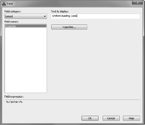
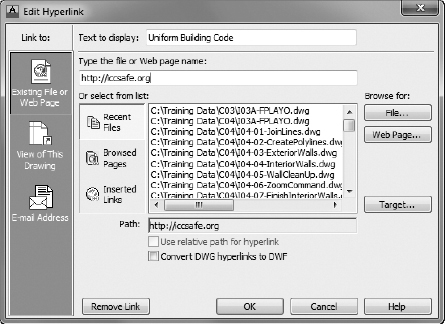
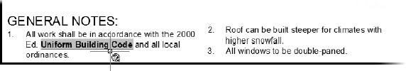
Your drawing should look like Figure 8.70.
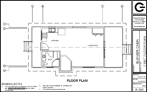
FIGURE 8.70 The cabin with the text added
Using the Spell-Check Feature
Like most programs with word processing capability, AutoCAD includes a spell-check feature to identify potential spelling errors. The spell check can be run to look for errors in a selected single-line or multiline text object. There is also a real-time spell-check feature to spot misspellings as you type and to suggest alternative words.
Real-Time Spell-Checking
Follow these steps to see the spell-check feature in action:
- Make sure I08-17-Hyperlink.dwg (M08-17-Hyperlink.dwg) is open.
- Zoom in to the notes at the bottom of the drawing area and move them up enough to allow space for one more line of text.
- Expand the Mtext window down to accommodate the next line of text.
- Double-click the notes, place the cursor just past the period at the end of the third note, and type Soler panels, by SolCorp, are available.. (You are intentionally misspelling solar.)
The fourth numbered note is appended to the others.
 From the contextual Text Editor tab, click the Spell Check button, s N found on the Spell Check panel, to enable spell check.
- Notice how the words Soler and SolCorp are underlined with a dashed line (see Figure 8.71).
FIGURE 8.71 The new line of text with the misspelled words
This is how the real-time spell-check tool identifies the words that the AutoCAD dictionary doesn't recognize.
- Position the cursor in the word Soler, and right-click to open a context menu. At the top of the menu are spelling suggestions.
- Click or pause the cursor over the More Suggestions options; then click Solar, as shown in Figure 8.72.
FIGURE 8.72 Using the context menu to replace a misspelled word
Soler is replaced with Solar in the selected Mtext.
Many words that you frequently use, such as company, city, or individual names, may not exist in the AutoCAD dictionary and will be flagged as misspelled words. You can easily add words to the dictionary to keep these words from being flagged repeatedly.
- Put the cursor in the word SolCorp, and right-click to open the context menu.
- Near the top of the menu, click Add To Dictionary (see Figure 8.73).
FIGURE 8.73 Adding a word to the AutoCAD dictionary
SolCorp is added to the AutoCAD dictionary and is no longer underlined.
- Save this drawing as I08-18-SpellCheck.dwg (M08-18-SpellCheck.dwg).
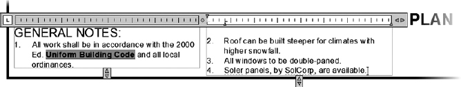
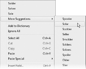
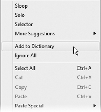
Spell-Checking an Entire Drawing
Often, drawings can have many separate text elements in the form of single-line text, multiline text, and dimensions. Although you can select each object individually, you can also run the Spell Check tool on the entire drawing. Here's how:
 Make sure I08-18-SpellCheck.dwg (M08-18-SpellCheck.dwg) is open.
- Make sure nothing is selected in the drawing. Then, under the Annotate tab, click the Check Spelling button in the Annotate tab Text panel.
- In the Check Spelling dialog box that opens, choose Entire Drawing in the Where To Check drop-down list and then click Start.
AutoCAD checks the entire drawing for words that do not exist in the dictionary, highlights them, and offers suggestions for apparently misspelled words, such as the initials RDG in Figure 8.74.
FIGURE 8.74 The Check Spelling dialog box and an unknown word
- When an unknown word is identified, you can do any of the following:
- Click Add To Dictionary to add the word to the AutoCAD dictionary.
- Click Ignore to take no action and continue searching the drawing for misspelled words.
- Click Ignore All to take no action and continue searching the drawing for misspelled words, ignoring all occurrences of the flagged word.
- Select a word in the Suggestions list, and then click Change to replace the flagged word with the suggested word.
- Select a word in the Suggestions list, and then click Change All to replace the flagged word with the suggested word and automatically substitute all occurrences of the flagged word for the suggested word.
- When the spell-checking task is finished, do the following:
- Click OK in the Spell Check Complete dialog box.
- Click Close in the Check Spelling dialog box.
- Perform a Zoom Extents, and then save this drawing as I08A-FPLAYO.dwg(M08A-FPLAYO.dwg).
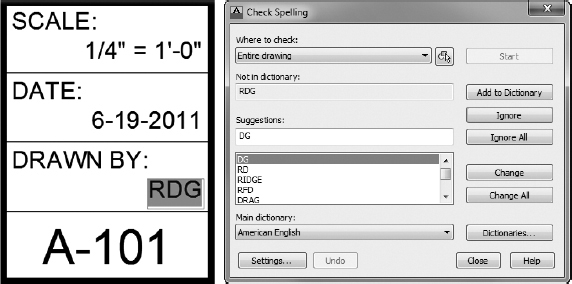
Exploring Other Aspects of Multiline Text
Multiline text has several other features that I can only touch on in this book. I encourage you to experiment with any features that you might find useful for your work.
Using Justification Points
Mtext has justification points similar to those of single-line text, and they behave the same way. The default justification point for Mtext, however, is the upper-left corner of the body of text, and the available options are for nine points distributed around the perimeter of the body of text and at the center (see Figure 8.75).
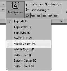
FIGURE 8.75 Justification points for Mtext
When you need to modify the justification of Mtext, double-click the text to open the Multiline Text Editor and display the Text Editor tab and panels. In the Paragraph panel, click the Justification button and then click the justification preference from the fly-out menu, as shown in Figure 8.75. I'll describe the other items on this menu in the following “Tools for Modifying Multiline Text” sidebar.
TOOLS FOR MODIFYING MUUILINE TEXT
Here's a brief summary of the various features of the contextual Text Editor tab's panels that are available whenever Mtext is selected with a double-click:
The Style Panel
Style List Lists all existing text styles in the drawing file.
Annotative Button Toggles the Annotative property for text and dimensions. This property can cause the text to scale automatically as necessary. Chapter 12 covers annotation.
Text Height Drop-Down Text Box Sets the height for selected text or sets the height for subsequently entered text.
The Formatting Panel
Bold, Italic, Underline, Overline, and Strikethrough Buttons Changes selected text or sets up for subsequently entered text.
Make Uppercase and Make Lowercase Fly-Out Button Changes the case of the selected text to all uppercase or all lowercase.
Font Drop-Down List Sets the font for the selected text or sets the font for subsequently entered text.
Color Drop-Down List Changes the color of a selected portion of text or sets a color for subsequently entered text.
Background Mask Button Sets the parameters for using a background mask to hide objects behind the text.
Oblique Angle Spinner Buttons Sets the selected text to an oblique angle off the vertical, from −85° to the left, to 85° to the right.
Tracking Spinner Buttons Adjusts the spacing between selected letters from a minimum of 75 percent of the default spacing to a maximum of four times the default spacing.
Width Factor Spinner Buttons Adjusts the width of selected letters and the spacing between them from a minimum of 10 percent of the default width and spacing to a maximum of 10 times the default.
Stack Creates fractions and tolerance forms by stacking text objects and mleaders.
Justification Button Displays a menu with the nine Mtext justification choices.
Bullets And Numbering Button Opens a fly-out menu for controlling numbering and bullets.
Line Spacing Button Opens a fly-out menu for controlling spacing between lines of text.
Combine Paragraphs Button Removes the line break between two or more paragraphs and combines them into a single paragraph.
Paragraph Button Clicking the arrow on the right opens the Paragraph dialog box, where you can set tab and paragraph spacing, indents, and other paragraph-related parameters.
Left, Center, Right, Justify, and Distribute Buttons Justifies the selected text accordingly.
The Insert Panel
Columns Button Opens a menu for controlling the column options.
Symbol Button Opens a menu of symbols to insert into the Mtext where the cursor rests.
Field Button Begins the process of inserting a field in the Mtext in place of selected text or where the cursor rests in the text.
The Spell Check Panel
Spell Check Button Runs the Spell Check utility.
Edit Dictionaries Opens the Dictionaries dialog box, where custom dictionaries can be selected and edited.
The Tools Panel
Find & Replace Button Opens the Find And Replace dialog box, where you can specify a text string to search for and the text string that will replace it.
Import Text Imports a word processing or text file into an AutoCAD drawing. The maximum size allowed is 32 KB, so the smallest document possible in some versions of Microsoft Word is too large. You can, however, use files in text-only or RTF formats. Clicking the Import Text button opens the Select File dialog box that displays only files with the .txt and .rtf extensions. You can bring in text files with other extensions if you enter the full filename with its extension and if the files aren't larger than 32 KB. Text comes in as Mtext and uses the current text style, height setting, and layer. The imported file might not retain complex code fields for such elements as tabs, multiple margin indents, and so on.
AutoCAPS When checked, this capitalizes all text.
The Options Panel
More Displays a menu with several options for adjusting the parameters for text, Mtext, and the Multiline Text Editor.
Ruler Button Toggles the ruler above the Mtext to be visible or invisible.
Undo Button Undoes the last editing action.
Redo Button Redoes the last undo.
The Close Panel
Close Button Deselects the Mtext, and closes the Multiline Text tab.
The Mtext Context Menu
The features of the Mtext context menu, the menu that appears when you place your cursor in the text or highlight text and right-click, are as follows:
Spelling Suggestions If the highlighted text is not in the dictionary, a set of suggested words is displayed along with a cascading menu with additional word options.
Add To Dictionary and Ignore All Two more actions available when misspelled words are highlighted.
Select All Selects and highlights all the text in the selected Mtext object.
Cut Copies the selected text to the Windows Clipboard and deletes it from the Mtext object.
Copy Copies the selected text to the Windows Clipboard.
Paste Pastes text from the Windows Clipboard to the cursor location in the Mtext objects.
Paste Special Displays a submenu containing additional methods for pasting content into an Mtext object.
Insert Field Opens the Field dialog box, which you use to insert a field into the selected text. If you select text containing a field, this menu item changes to three menu items: Edit Field, Update Field, and Convert Field To Text.
Symbol Imports symbols (such as diameter, degree, and so on) that aren't available in the font you're using.
Import Text Imports a word processing or text file into an AutoCAD drawing, as described under “The Tools Panel” earlier in this sidebar.
Paragraph Alignment Sets the justification for the selected Mtext.
Paragraph Opens the Paragraph dialog box. It has settings for indenting the first line and subsequent paragraphs of Mtext (similar to what the sliders do on the ruler above the Multiline Text Editor window) and tab stop positions.
Bullets And Lists Opens a fly-out menu that offers various options for using the listing features.
Columns Provides access to the column parameters.
Find And Replace Opens the Replace dialog box, in which you search for a word or a series of words (text string) and replace them with text that you specify.
Change Case Changes the case of all highlighted text to uppercase or lowercase.
AutoCAPS When checked, capitalizes all text.
Character Set Opens a menu of several languages. When applicable, the codes of the selected language are applied to selected text.
Combine Paragraphs Joins highlighted individual paragraphs into one paragraph.
Remove Formatting Removes formatting, such as bold, underline, and so on, from highlighted text.
Background Mask Opens the Background Mask dialog box in which you specify color for and activate a background mask to go behind the selected Mtext object.
Editor Settings Opens a menu where you can select whether certain features appear, such as the ruler or toolbar.
Help Opens the AutoCAD Help file at the entry regarding Mtext.
Cancel Closes the menu.
Adding Special Characters
With Mtext, you can add special characters—the degree symbol, the diameter symbol, and so on—that aren't included in most font character packages. You'll have a chance to do this in Chapter 12.
If you want to experiment with the Mtext in the cabin drawing, make a copy of it and place it outside the title block. Double-click it, and see what you can learn about the Multiline Text Editor, the tools found in the panels located under the Multiline Text tab, and the Mtext shortcut menu. The preceding “Tools for Modifying Multiline Text” sidebar summarizes the features of the latter two.
If You Would Like More Practice…
Trades and professions other than architecture and construction use text with AutoCAD and AutoCAD LT in the same way as demonstrated in this chapter.
For more practice using single-line text, follow these steps:
- Close all drawings, and then open 08A-FPGARG.dwg.
- Using the DesignCenter, bring in the A-Title and A-Label text styles from the 08A-FPLAYO drawing while it's closed.
- Place labels on the features that were added:
- Use the A-Title text style to identify the addition as GARAGE.
- Use the A-Label text style to give the features the following names: WALKWAY, STORAGE, OFFICE, and CAR.
For more practice using Mtext, follow these steps:
- Open 08A-FPLAYO, and zoom in to the blank space between the notes and the title block.
- Create a new text style called A-Desc that uses the Times New Roman font and a height of 8″ (204 mm).
- Start Mtext, and specify a rectangle for the text that covers the area between the notes and the title bar.
- Enter the following text exactly as shown here, spelling errors and all:
This is a design for a small vaction cabin. It contains approximately 380 square feet of living space and includes one bedroom and one bath. It can be adopted to provide shelter in all climates and can be modified to allow constuction that uses local building materials. Please sund all inquiries to the manufacturer.
- Double-click the new text and make these changes:
- Correct all spelling errors by using the Spell Check tool or real-time spell checking.
- Change square feet to sq. ft.
- Bold the following: one bedroom, one bath, all climates, and local building materials.
- Italicize the last sentence.
Are You Experienced?
Now you can…
- Set up text styles
- Place single-line text in a drawing for titles and room labels
- Create a structural grid for a drawing
- Modify single-line text
- Construct a title block and place text in it
- Open AutoCAD template files
- Place Mtext in a drawing
- Modify Mtext in several ways
- Add a hyperlink to an Mtext object
- Check the spelling in a drawing