
CHAPTER 4
Developing Drawing Strategies: Part 1
Assuming that you have worked your way through the first three chapters, you have now successfully drawn a shape (Chapter 2, “Learning Basic Commands to Get Started”) as well as the outer wall lines of a cabin (Chapter 3, “Setting Up a Drawing”). From here on, you'll develop a floor plan for the cabin.
The focus in this chapter is on gaining a feel for the strategy of drawing in the Autodesk® AutoCAD® program and on solving drawing problems that come up in the course of laying out a floor plan. As you work your way through this chapter, the activities will include making the walls, cutting doorway openings, and drawing the doors. In the next chapter, you'll add steps and two decks, and you'll place fixtures and appliances in the bathroom and kitchen.
Each exercise in this chapter presents opportunities to practice using commands you learned in earlier chapters and to discover a few new ones. Arguably, more important than knowing a large number of AutoCAD commands is the ability to take those commands and establish how to combine them to complete the design at hand. As you work through the exercises in this chapter and the next, I encourage you to focus less on knowing the commands themselves and more on how they are used to get you one step closer to a finished design. Admittedly, separating the two can be hard at times; however, developing a strong sense of strategic thinking now will undoubtedly make you a more efficient user.
In this chapter, you will learn to
- Make interior walls
- Zoom in on an area using various zoom tools
- Make doors and swings
- Use object snaps
- Use the COPY and MIRROR commands
Laying Out the Walls
For most floor plans, the walls come first. As you begin to define the interior of your cabin further by adding a closet and bathroom, certain relationships can be established with lines already in your drawing. By taking a moment to recognize these relationships, you won't need to draw as many new lines as you might expect. In this chapter, I'll show you how to build most of the new walls from the four exterior wall lines you drew in the previous chapter.
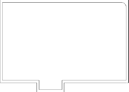
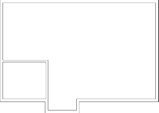
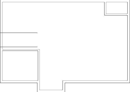
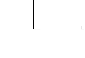
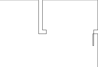
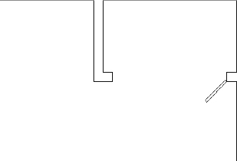
Take a moment to study the floor plan in Figure 4.1 to begin visualizing the many relationships that exist between the exterior wall boundary drawn in Chapter 3 (shown in bold) and the remaining linework that makes up the floor plan. One easily identified relationship is the lines that create the exterior wall definition. Most of the final exterior wall definition follows the outline drawn in Chapter 3. For this reason, the best strategy is to build upon the existing line-work in your drawing by using a series of commands found on the Modify panel on the Home tab of the Ribbon.
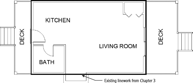
FIGURE 4.1 The exterior wall boundary drawn in Chapter 3 overlaid onto the cabin floor plan
It's possible to apply a similar strategy as both the bathroom and closet are considered. Both spaces share similar relationships with the exterior wall definitions adjacent to them. Because Modify commands allow new objects to be created from existing objects, these relationships are easily maintained as the spaces are defined.
Afterward, you'll cut four openings in these walls (interior and exterior) for the doorways.
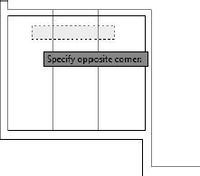
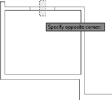
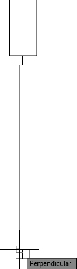
![]()
Because you'll be doing quite a bit of drawing in this and the next chapter, this is a good opportunity to activate the Dynamic Input feature introduced in Chapter 3 if you've turned it off. Because the purpose of this chapter is to develop drawing strategies, try turning it on and off as you work through the exercises. You'll see how the information displayed in the drawing area changes as you move from one command to another.
Commands that you enter appear only at the cursor and not at the command-line interface while Dynamic Input is active. The feature is designed to help you avoid having to glance down continually at the command-line interface as you work through the steps of a command. Sometimes, however, the information you need is displayed only in the command line, so you still have to glance down at it. By the time you finish Chapter 5, “Developing Drawing Strategies: Part 2,” you'll know whether you want the feature to be active or not.
Creating Polylines from Existing Objects
Exterior walls are slightly thicker than interior walls because they are sturdier, are load bearing, and have an additional layer or two of weather protection such as siding or stucco. Accounting for these properties, the standard thickness for your exterior walls will be 6″ (150 mm). Using the tools you've already learned, you'll apply the strategy outlined at the start of this chapter to offset the four existing wall lines to the inside, creating the exterior wall definition.
Most of the commands used in this exercise were presented in Chapters 2 and 3. If you need a refresher, glance back at those chapters.
This section introduces the use of polylines as an alternative to the FILLET command. Whereas a line is a single, straight object with no measurable width, polylines are composed of several straight or curved segments that can also maintain a user-defined width. When a polyline is offset, all segments are offset equally, and the corners are left sharp without the need to use the FILLET command to clean them up. Any polyline can be disassembled into its component lines and arcs by using the EXPLODE command.
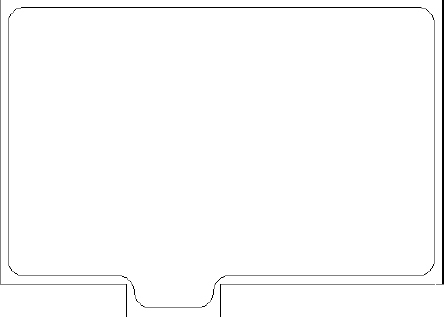
The JOIN command allows objects of different types to be joined into a polyline. By using the JOIN command, you can convert any combination of lines and arcs into a single polyline, as long as the endpoints of the various segments terminate in exactly the same location. Because polylines are treated as a single object, converting the outermost perimeter into a single polyline will automate much of the cleanup as you continue creating the floor plan shown in Figure 4.2.
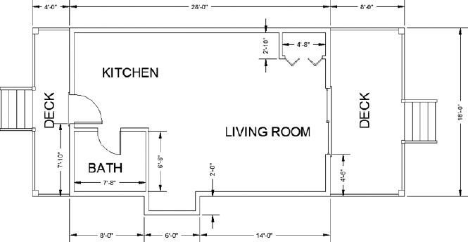
FIGURE 4.2 The wall dimensions
In this exercise, you will create a polyline from the individual line segments composing the outside wall:
With AutoCAD running, choose Application menu
 Open Drawing.
The Select File dialog box opens, where you can navigate to the I03A-FPLAYO.dwg (M03A-FPLAYO.dwg) file you saved at the end of Chapter 3. Click Open to display the cabin drawing shown in Figure 4.3.
FIGURE 4.3 The cabin as you left it in Chapter 3
- Click the Grid Display and Snap Mode icons on the status bar to turn them off (they'll change to a gray background). Alternatively, you can press F7 to turn off Grid Display and F9 to turn off Snap mode.
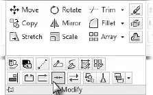
 Expand the Modify Ribbon panel found on the Home tab, and click Join, as shown in Figure 4.4. Command-line users can type J
 to start the JOIN command.
FIGURE 4.4 Starting the JOIN command
Select one of the exterior wall lines.
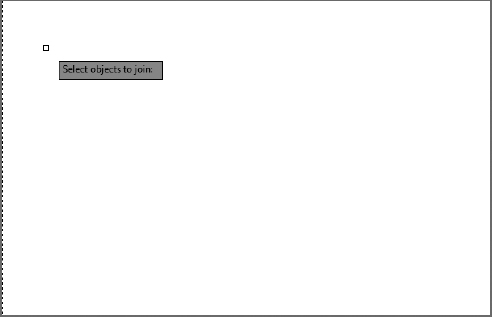
The line ghosts, and the command line prompts you to select objects to join to the line you just selected, as shown in Figure 4.5.
FIGURE 4.5 The command line after choosing an object to join
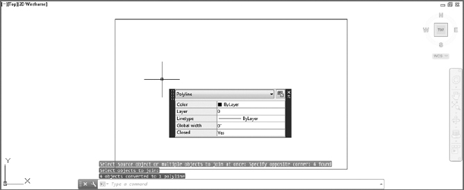
Select the remaining three exterior wall lines, and press the
key to accept the selection set.After accepting the selection set, the command line confirms the Join action and reads 4 objects converted to 1 polyline, as shown in Figure 4.6.
FIGURE 4.6 The command-line interface after converting the lines into a single polyline
Select one segment of the polyline that forms the perimeter of the box in the drawing area.
As shown in Figure 4.6, all four polyline segments are selected (dashed), indicating that they exist as a single object, and blue boxes appear at the corners along with blue rectangles at the midpoint of each segment. The blue boxes and rectangles, called grips, appear because you selected the object outside of a command. Grips are not exclusive to polylines. Grips are explained in Chapter 8, “Controlling Text in a Drawing.”
- Save your drawing as I04-01-JoinLines.dwg (M04-01-JoinLines.dwg) by choosing Application menu Save As AutoCAD Drawing.
Creating and Editing Polylines
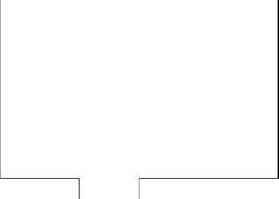
Polylines are composed of segments, which may be straight or curved lines, and vertices that terminate the segments. Each segment must have a vertex at each end, but several segments can share a single vertex. The perimeter that you drew follows the major length and width dimensions of the cabin but doesn't account for the small pop-out on the south side of the structure. In this exercise, you will add the pop-out, trim the original polyline, and then join the two polylines into a single entity:
- If I04-01-JoinLines.dwg(M04-01-JoinLines.dwg) is not already open, click the Open button on the Quick Access toolbar.

Click the Polyline button in the Draw panel on the Home tab of the Ribbon to start the polyline (PLINE) command. Alternatively, you can type PL
at the command line.At the Specify start point: prompt, type 16',8'
(4850.2500).With the Dynamic Input feature turned on, the comma not only designates the X and Y locations for the start point, but it also instructs AutoCAD to switch the current input field from the X field to the Y field.
When Dynamic Input is turned off, the values that you type are shown in the command-line interface.
A rubber-banding line, similar to the one you saw when you used the LINE command, is attached to the point you designated and to the cursor.
- Type the following:
Your screen should look like Figure 4.7.
FIGURE 4.7 The pop-out added to the cabin
- Start the TRIM command.
At the Select Objects or <select all>: prompt, pick the pop-out that you just drew and press
.All segments of the pop-out are ghosted to indicate that the entire polyline is designated as a cutting edge.
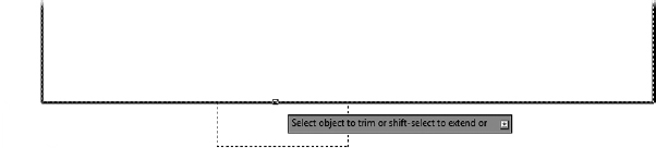
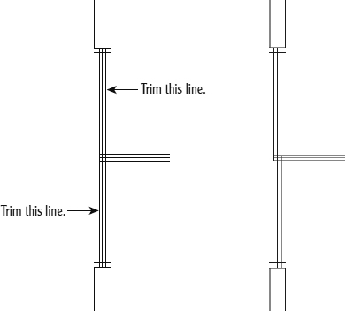
- Trim the pop-out by selecting it as the cutting edge. When prompted to Select object to trim or shift-select to extend or, select the long horizontal line of the cabin between the two vertical lines that define the pop-out, as shown in Figure 4.8.
FIGURE 4.8 Selecting the polyline segment to trim away
- Press to end the TRIM command.
- From the expanded Modify panel on the Home tab, choose Join and then pick either of the two polylines.
- Pick the other polyline and press .
Your drawing now consists of a single polyline made up of eight segments, as shown in Figure 4.9.
FIGURE 4.9 The polyline after trimming the original and then joining the remaining entities
- Save your drawing as I04-02-CreatePolylines.dwg (M04-02-CreatePolylines.dwg) by choosing Application menu Save As AutoCAD Drawing.
Creating the Exterior Wall Lines
Here you will use the OFFSET command to create all the interior lines for the exterior walls at one time:
- If I04-02-CreatePolylines.dwg (M04-02-CreatePolylines.dwg) is not already open, click the Open button on the Quick Access toolbar.
 Start the OFFSET command by clicking the Offset button on the Modify panel. Command-line users can type 0 to start the OFFSET command.
- At the Specify offset distance or: Dynamic Input prompt, type 6 (150).
 NOTE: You don't have to enter the inch sign (″), but you're required to enter the foot sign (′) when appropriate.
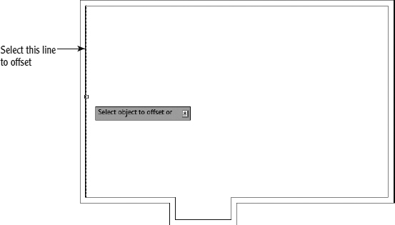
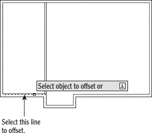
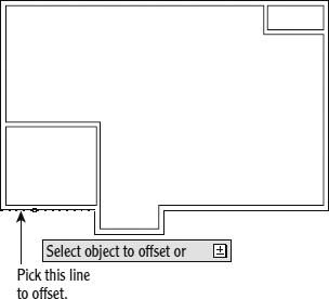
 - At the Select object to offset or: prompt, select the polyline.
- Click in a blank area inside the cabin's perimeter. All segments of the polyline are offset 6″ (150 mm) to the inside (see Figure 4.10).
FIGURE 4.10 All line segments are now offset 6″ (150 mm) to the inside.
The OFFSET command is still running; press
to terminate it.As you can see, there is no need to fillet the corners, and using polylines can reduce the number of steps and picks required to draw the inside lines. We'll diverge from the cabin exercise briefly to examine the capabilities of the FILLET command when used in conjunction with polylines.
 Start the FILLET command by clicking the Fillet button from the Modify panel on the Home tab.
You can restart the most recently used command by pressing the spacebar or
 at the command prompt or by right-clicking and choosing the Repeat option from the context menu.
- Click Radius, or type R, at the command line to select the Radius option; then set the radius to 12″ (3600mm).
Select any two polyline segments that share a corner of the inner box.
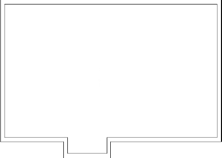
The two segments are shortened, and a curved segment with a 12″ radius is inserted. The polyline now has nine contiguous segments (see Figure 4.11). The FILLET command automatically ends after each fillet.
FIGURE 4.11 The first corner is filleted.
- Press or the spacebar to restart the FILLET command.
- Type P, or select Polyline at the command line to instruct AutoCAD that the fillet is to be performed on all intersections of a polyline.
- At the Select 2D polyline: prompt, select the inner box. All corners are now filleted (see Figure 4.12).
FIGURE 4.12 The polyline's corners are filleted.
You can see how the FILLET command, when used with a polyline, can save time.
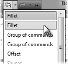
 You don't want the objects to remain as polylines for this project, so click the Undo button on the Quick Access toolbar, or type U, until all of the filleted edges are square again.
 TIP: Selecting the down-arrow next to the Undo button on the Quick Access toolbar will display a list of recently executed commands so that you can undo multiple commands at once.
You can also use the Windows standard Ctrl+Z keyboard combination to undo AutoCAD actions.
 Click the Explode button on the Home tab Modify panel, or type X to start the EXPLODE command.
Select both of the polylines and then press the
key. The two polylines are now 16 separate line objects.You will be using the OFFSET command to create the interior walls from the lines that make up the exterior walls. Exploding the polylines into individual line objects allows you to offset single, straight objects rather than the closed polylines that would require trimming to clean up.
- Save your drawing as I04-03-ExteriorWalls.dwg (M04-03-ExteriorWalls.dwg) by choosing Application menu Save As AutoCAD Drawing.
Creating the Interior Walls
Because the interior walls of your cabin are not load bearing, they can be a little thinner than the exterior walls. The standard thickness for your interior walls will be 4″ (100 mm). Using the strategy developed at the start of this chapter, you will create the cabin's interior wall lines by offsetting the exterior wall lines:
- Make sure the drawing I04-03-ExteriorWalls.dwg (M04-03-ExteriorWalls.dwg) is open; if it's not, click the Open button on the Quick Access toolbar.
- Start the OFFSET command.
- At the Specify offset distance or: prompt, type 7'8 (2350). Leave no space between the foot sign (′) and the 8.
NOTE: AutoCAD requires that you enter a distance containing feet and inches in a particular format: no space between the foot sign (′) and the inches value, and a hyphen (-) between the inches and a fraction. For example, if you're entering a distance of
 , you enter
  . The measurement is displayed in the normal way, , but you must enter it in the format that has no spaces because the spacebar acts the same as in most cases.
 - Click the inside line of the left exterior wall (see Figure 4.13).
- Click in a blank area to the right of the selected line. The line is offset 7′-8″ (2250 mm) to the right.
Press
twice, or press the spacebar twice.The OFFSET command is terminated and then restarted, and you can reset the offset distance.
TIP: In the OFFSET command, your opportunity to change the offset distance comes right after you start the command. So, if the OFFSET command is already running and you need to change the offset distance, you must stop and then restart the command. To do so, press or the spacebar twice.FIGURE 4.13 Selecting the wall line to offset
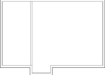
- Type 4 (100) to reset the offset distance to 4″ (100 mm).
- Click the new line that was just offset, and then click in a blank area to the right of that line. You have created a vertical interior wall (see Figure 4.14).
FIGURE 4.14 The first interior wall
- Press twice to stop and restart the OFFSET command.
Type 6.5'
(1980) to set the distance for offsetting the next wall.- Pick a point on the inside lower-left exterior wall line (see Figure 4.15).
FIGURE 4.15 Selecting another wall line to offset
- Click in a blank area above the line selected. The inside exterior wall line is offset to make a new interior wall line.
- Press the spacebar twice to stop and restart the OFFSET command.
- Type 4 (100). Click the new line, and click again above it. A second wall line is made, and you now have two interior walls.
- Press the spacebar to end the OFFSET command.
- Save your drawing as I04-04-InteriorWalls.dwg (M04-04-InteriorWalls.dwg).
These interior wall lines form the boundary of the bathroom. You need to clean up their intersections with each other and with the exterior walls. If you take the time to do this properly, it will be easier to make changes in the future. Refer to Figure 4.2 earlier in this chapter to see where we're headed.
Cleaning up Wall Lines
Earlier in the book, you used the FILLET command to clean up the corners of intersecting lines. You can use that command again to clean up some of the interior walls, but you'll have to use the TRIM command to do the rest of them. You'll see why as you progress through the next set of steps:
- Make sure I04-04-InteriorWalls.dwg (M04-04-InteriorWalls.dwg) is open.
 Assuming you have a mouse with a scroll wheel, double-click the scroll wheel to zoom to the extents of your drawing. Alternatively, you can use the Zoom Extents button found on the navigation bar or type Z E at the command line.
Performing a Zoom Extents will make it easier to pick the wall lines by making the drawing larger on the screen.
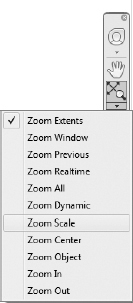
 Expand the Zoom option found on the navigation bar (Figure 4.16) and click Zoom Scale.
FIGURE 4.16 Selecting the Zoom Scale option from the navigation bar
When prompted to Enter a scale factor, type 0.75x
. The drawing zooms out a bit.You've just used two options of the ZOOM command. First, you used Zoom Extents to display all the objects in your drawing. You then zoomed to a scale (0.75′) to make the drawing 75 percent the size it was after using Zoom Extents. This is a change in magnification on the view only; the building is still 28′ (8550 mm) long and 18′ (5490 mm) wide.
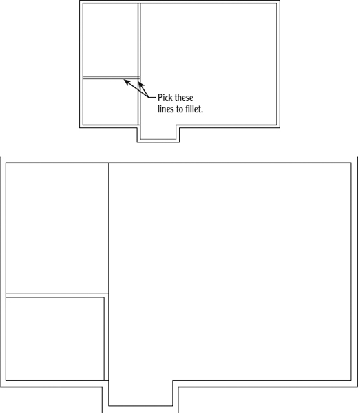
- Start the FILLET command, set the radius to 12, and then press to exit the FILLET command.
- Restart the FILLET command. Press and hold the Shift key as you click the two interior wall lines shown at the top of Figure 4.17. The lines are filleted, and the results will look like the bottom of Figure 4.17.
FIGURE 4.17 Selecting the first two lines to fillet (top) and the result of the fillet (bottom)
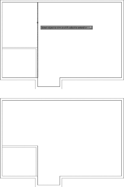
NOTE: Pressing and holding the Shift key as you select objects with the FILLET command temporarily overrides the current radius and sets it to a value of 0. In the previous example, the fillet radius value was set to 12; however, because the Shift key was pressed, the command worked as if you had set the radius to 0. Start the TRIM command, and press
to skip the Select cutting edges… Select objects: prompt. This makes every edge in the drawing a cutting edge.Select the vertical line shown at the top of Figure 4.18. The results are shown at the bottom of Figure 4.18.
FIGURE 4.18 Selecting the second two lines to fillet (top) and the result of the second fillet (bottom)
- Save your drawing as I04-05-WallCleanUp.dwg (M04-05-WallCleanUp.dwg).
The two new interior walls are now the correct length, but you'll have to clean up the areas where they form T-intersections with the exterior walls. The FILLET command won't work in T-intersections because too much of one of the wall lines gets deleted. You need to use the TRIM command in T-intersection cases. The FILLET command does a specific kind of trim and is easy and quick to execute, but its uses are limited (for the most part) to single intersections between two lines or multiple intersections on a polyline.
Here's the best rule for choosing between FILLET and TRIM: If you need to clean up a single intersection between two lines, use the FILLET command. For other cases, use the TRIM command.
Using the Zoom Command
To do this trim efficiently, you need a closer view of the T-intersections. Use the ZOOM command to get a better look:
- Make sure I04-05-WallCleanUp.dwg (M04-05-Wa11CleanUp.dwg) is open.
- Type Z. Then move the crosshair cursor to a point slightly below and to the left of the upper T-intersection (see Figure 4.19), and click in a blank area outside the floor plan.
FIGURE 4.19 Positioning the cursor for the first click of the ZOOM command
Move the cursor up and to the right, and notice a rectangle with solid lines being drawn. Keep moving the cursor up and to the right until the rectangle encloses the upper T-intersection (see the top of Figure 4.20).
FIGURE 4.20 Using the Zoom Window option: positioning the rectangle (top) and the new view after the ZOOM command (bottom)
When the rectangle fully encloses the T-intersection, click again. The view changes to a closer view of the intersection of the interior and exterior walls (see the bottom of Figure 4.20).
The rectangle you've just specified is called a zoom window. The area of the drawing enclosed by the zoom window becomes the view on the screen. This is one of several zoom options for changing the magnification of the view. Other zoom options are introduced later in this chapter and throughout the book.
When you start the ZOOM command by typing Z
and then picking a point on the screen, a zoom window begins. From the Home tab Modify panel, click the Extend button.
In the command-line interface, notice the second and third lines of text. You're being prompted to select boundary edges (objects to use as limits for the lines you want to extend/trim).
- Select the two horizontal interior wall lines, and press the spacebar or . The prompt changes and asks you to select the objects to be extended.
Press and hold the Shift key while you select the inside exterior wall line at the T-intersection that is between the two intersections with the interior wall lines that you have just picked as boundary edges (see the top of Figure 4.21).
FIGURE 4.21 Selecting a line to be trimmed (top) and the result of the EXTEND command used in conjunction with the Shift key (bottom)
The exterior wall line is trimmed at the T-intersection (see the bottom image of Figure 4.21). Press the spacebar to end the TRIM command.
NOTE: As you've just seen with the FILLET command, pressing and holding the Shift key temporarily overrides the normal functionality of a command. For the FILLET command, the radius is temporarily set to 0. When the Shift key is used with the EXTEND command, it temporarily functions like the TRIM command. Conversely, when used with the TRIM command, it functions like the EXTEND command.Return to a view of the whole drawing by typing Z
and then P.This is the ZOOM command's Previous option, which restores the view that was active before the last use of the ZOOM command (see Figure 4.22). This command is also available from the Zoom fly-out button on the navigation bar.
FIGURE 4.22 The result of the Zoom Previous command
Repeat the procedure to trim the lower T-intersection. Follow these steps:
- Type Z, and click two points to make a rectangular zoom window around the intersection.
- Start the TRIM command, select the interior walls as cutting edges, and press the spacebar.
- Select the inside exterior wall line between the cutting edges.
- Press the spacebar or to end the TRIM command.
- Zoom Previous by typing Z P. Figure 4.23 shows the results.
FIGURE 4.23 The second trim is completed.
- Save your drawing as I04-06-ZoomCommand.dwg (M04-06-ZoomCommand.dwg).
You need to create one more set of interior walls to represent the closet in the upper-right corner of the cabin.
Finishing the Interior Walls
You'll use the same method to create the closet walls that you used to make the first two interior walls. Briefly, this is how it's done:
- Make sure I04-06-ZoomCommand.dwg (M04-06-ZoomCommand.dwg) is open.
- Offset the inside line of the upper exterior wall 2′-6″ (762 mm) downward; then offset this new line 4″ (100 mm) downward (see Figure 4.24).
- Offset the inside line of the right exterior wall 4′-8″ (1420 mm) to the left; then offset this new line 4″ (100 mm) to the left (see Figure 4.25).
- Use a zoom window to zoom in to the closet area.
FIGURE 4.24 Offsetting the lines for the first wall
FIGURE 4.25 Offsetting the lines for the second wall
TIP: Make a zoom window just large enough to enclose the closet. The resulting view should be large enough to allow you to fillet the corners and trim the T-intersections without zooming again. - Use the FILLET command to clean up the interior and exterior wall line intersections, as shown in Figure 4.26.
FIGURE 4.26 Fillet the two corners.
Use the TRIM command to trim away the short portions of the intersecting wall lines between the two new interior walls.
This can be accomplished with one use of the TRIM command. After you select all four of the new wall lines as cutting edges, you can trim both lines that run across the ends of the selected lines to those same cutting edges.
Use Zoom Previous (ZOOM
P) to restore the previous view.The results should look like Figure 4.27.
- Save your drawing as I04-07-FinishInteriorWalls.dwg (M04-07-FinishInteriorWalls.dwg).


You used OFFSET, FILLET, TRIM, and a couple of zooms to create the interior walls. By combining these commands, you were able to build the interior walls from the existing exterior wall definition—harnessing the relationship between both the new and existing walls. The next task is to create four doorway openings in the interior and exterior walls. A similar strategy, employing these same commands, will be used to complete this task.

FIGURE 4.27 The completed interior walls
Cutting Openings in the Walls
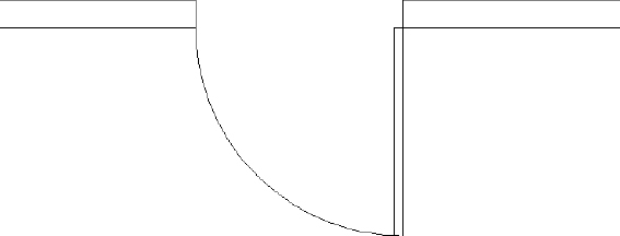
Of the four doorway openings needed, two are on interior walls and two are on exterior walls (see Figure 4.28). Two of the openings are for swinging doors, one is for a sliding glass door, and one is for a set of bifold doors. You won't be doing the hatchings and dimensions shown in the figure—those features will be covered in future chapters.
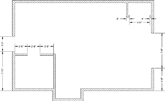
FIGURE 4.28 The drawing with doorway openings
The procedure used to make each doorway opening is the same one that you used to create the opening for the box in Chapter 2. First you establish the location of the jambs, or sides, of an opening. After the location of one jamb is located, the line defining that side is offset by the width of the door opening. When the jambs are established, you'll trim away the wall lines between the edges. The commands used in this exercise are OFFSET, EXTEND, and TRIM. You'll make openings for the 3′-0″ (915 mm) exterior doorway first.
Creating the 3′-0″ (915 mm) Exterior Opening
This opening is on the back wall of the cabin and has one side set in 7′-10″ (2388 mm) from the outside corner:
- Make sure I04-07-FinishInteriorWalls.dwg (M04-07-FinishInteriorWalls.dwg) is open.
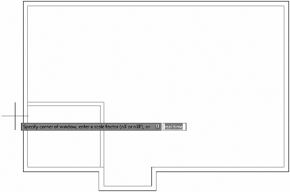
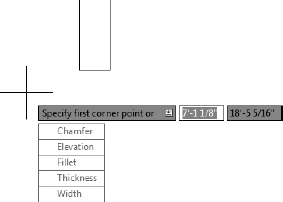
- Start the OFFSET command, and then type 7′10 (2388) to set the distance to 7′-10″ (2388 mm).
Click the lower outside line indicated in Figure 4.29, and then click in a blank area above the line you selected.
FIGURE 4.29 Selecting the line to offset
You have to offset one line at a time because of the way the OFFSET command works.
- End and restart the OFFSET command by pressing the spacebar or twice; then type 3′ (915) to set a new offset distance, and offset the new line upward (see Figure 4.30).
FIGURE 4.30 The offset line for the 3′-0″ (915 mm) opening
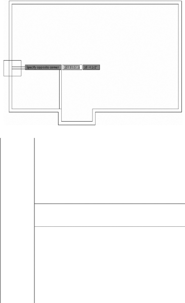
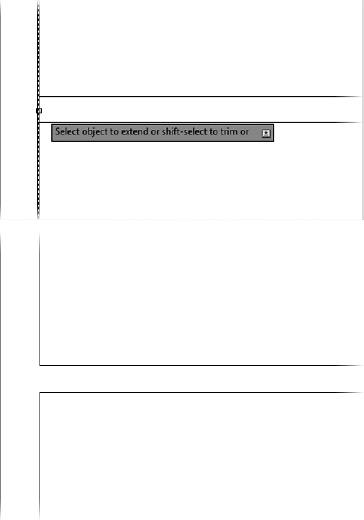
- Start the TRIM command, and press to skip the cutting edges prompt.
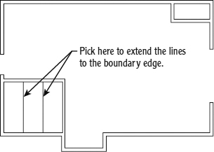
- When asked to Select object to trim, enter F or select Fence from the command line.
- Draw a fence line as shown at the top of Figure 4.31. The result should look like the bottom of Figure 4.31.
- Save your drawing as I04-08-3ftExterior.dwg (M04-08-915mmExterior.dwg).
Creating the 7′-0″ (2134 mm) Opening
Take another look at Figure 4.28, and notice that the opening on the right side of the building has one jamb set in 4′-6″ (1372 mm) from the outside corner. This opening is for the sliding glass door.
You've done this procedure before, so here's a quick summary of the steps:
- Make sure I04-08-3ftExterior.dwg (M04-08-915mmExterior.dwg) is open.
- Offset the lower exterior wall line 4′-6″ (1372 mm).
- Offset the new line 7′-0″ (2134 mm).
FIGURE 4.31 Using the Trim Fence option to trim away the unneeded lines
- Use the Trim Fence option used to clean up the 3′-0″ opening to complete the opening. Your cabin should look like Figure 4.32.
- Save your drawing as I04-09-7ftExterior.dwg (M04-09-2134mmExterior.dwg).
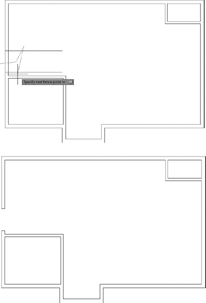
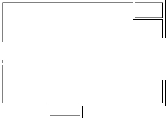
FIGURE 4.32 The cabin with the 7′-0″ (2134 mm) sliding door opening
Creating the 2 ′-6″ (762 mm) Interior Opening
The 2′-6″ (762 mm) opening to the bathroom starts 30″ (762 mm) from the inside of the left exterior wall. You can't simply offset the wall and trim the excess because the offset lines would not cross both the interior wall lines. So instead you will use the EXTEND command exactly as you used it in Chapter 2:
- Make sure I04-09-7ftExterior.dwg (M04-09-2134mmExterior.dwg) is open.
- Start the OFFSET command and offset the interior line of the lower-left exterior wall 2′-6″ (762 mm) to the right. Then offset the new line another 2′-6″ (762 mm) to the right.
- Start the EXTEND command, and then press the spacebar or to make every edge in the drawing a boundary edge. TIP: If you start a new command by entering letters on the keyboard, you must first make sure that the previous command has ended by pressing the Esc key at least twice. On the other hand, if you start a new command by clicking its icon on the Ribbon, it doesn't matter whether the previous command is still running. AutoCAD will cancel it.
Click the two jamb lines to extend them. Be sure to pick points on the lines that are near the ends that you want to extend, as shown in Figure 4.33, or the lines will be extended in the opposite direction.
FIGURE 4.33 The lines after being extended through the bathroom walls
The lines are extended through the interior walls to make the jambs (see Figure 4.33).
Keeping the EXTEND command active, you'll use the Shift key to trim away the excess lines and complete the openings. You'll do this by creating two crossing windows—first to trim the excess part of the jamb lines and then the wall lines between the jamb lines.
With the EXTEND command still active, press and hold the Shift key. Keeping it pressed, select a point to the right side of the bathroom and then another to the left, as shown in Figure 4.34.
FIGURE 4.34 Using a crossing window in conjunction with the Shift override within the EXTEND command to trim lines
Repeat the same process you used in the previous steps. With the EXTEND command still active, press and hold the Shift key to create a crossing window through the wall, as shown in Figure 4.35. Press
to exit the EXTEND command.FIGURE 4.35 Trimming the wall opening by using a Shift key override within the EXTEND command
Save your drawing as I04-10-30inInterior.dwg (M04-10-762mmInterior.dwg).
Your cabin should appear as shown in Figure 4.36.
You can construct the closet opening by using the same procedure.
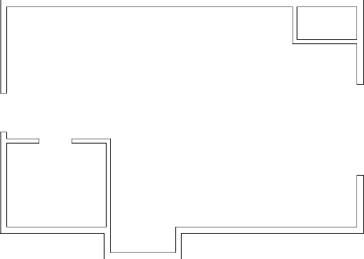
FIGURE 4.36 The cabin after creating the opening for the bathroom door
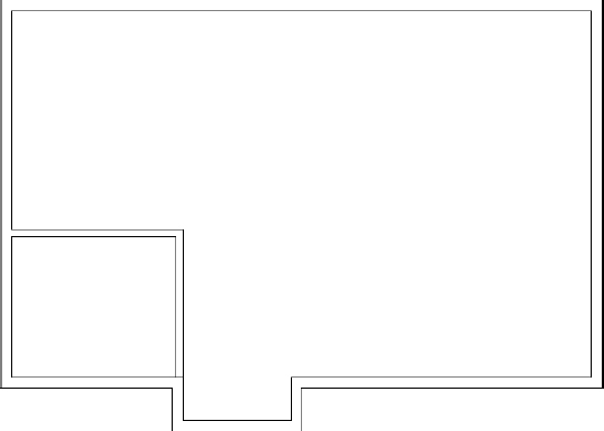
Creating the Closet Opening
This doorway is 4′-0″ (1220 mm) wide and has one jamb set in 4″ (100 mm) from the inside of the exterior wall. Figure 4.37 shows the three stages of fabricating this opening:
- The offset lines that locate the jamb lines (top left)
- The extended lines that form the jamb lines (top right)
- The completed openings after trimming (bottom)
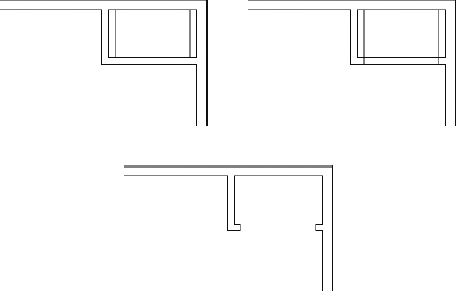
FIGURE 4.37 Creating the interior openings
- Make sure I04-10-30inInterior.dwg (M04-10-762mmInterior.dwg) is open.
- Use any combination of the OFFSET, TRIM, and EXTEND commands to create the 4′-0″ (1220 mm) closet opening. Refer to the previous section on making openings for step-by-step instructions.
- This completes the openings. Save your drawing as I04-11-ClosetOpening.dwg(M04-11-Closetopening.dwg). The results should look like Figure 4.38.
As you gain more control over the commands you used here, you'll be able to anticipate how much of a task can be accomplished with each use of a command. Each opening required offsetting, extending, and trimming. It's possible to do all the openings by using each command only once. In this way, you do all the offsetting, then all the extending, and finally all the trimming. In cutting these openings, however, the arrangement of the offset lines determined how many cycles of the TRIM command were the most efficient to use. If lines being trimmed and used as cutting edges cross each other, the trimming becomes complicated. For these four openings, the most efficient procedure is to use each command twice. In Chapter 8, you'll get a chance to work with more complex, multiple trims when you draw the elevations.
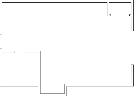
FIGURE 4.38 The completed doorway openings
WHAT TO DO WHEN YOU MAKE A MISTAKE
When you're offsetting, trimming, and extending lines, it's easy to pick the wrong line, especially in a congested drawing. Here are some tips on how to correct these errors and get back on track:
- You can always cancel any command by pressing the Esc key until you see the Type a Command: prompt in the command-line interface. Then click the Undo button on the Quick Access toolbar to undo the results of the last command. If you undo too many commands, click the Redo button. You can click it more than once to redo several undone commands. Redos must be performed immediately following an undo.
- Errors possible with the OFFSET command include setting the wrong distance, picking the wrong line to offset, and picking the wrong side to offset toward. If the distance is correct, you can continue offsetting, end the command when you have the results you want, and then erase the lines that were offset wrong. Otherwise, press Esc and undo your previous offset.
- Errors made with the TRIM and EXTEND commands can sometimes be corrected on the fly; you don't have to end the command, because each of these commands has an Undo option. If you pick a line and it doesn't trim or extend the correct way, you can undo that last action without stopping the command and then continue trimming or extending. You can activate the Undo option used while the command is running in two ways: type U, or right-click and choose Undo from the context menu. Either of these actions undoes the last trim or extend, and you can try again without having to restart the command. Each time you activate the Undo option from within the command, another trim or extend is undone.
- The LINE command has the same Undo option as the TRIM and EXTEND commands. You can undo the last segment drawn (or the last several segments) and redraw them without stopping the command.
Now that the openings are complete, you can place doors and door swings in their appropriate doorways. In doing this, you'll be introduced to two new objects and a few new commands, and you'll have an opportunity to use the OFFSET and TRIM commands in new, strategic ways.
Creating Doors
In a floor plan, a rectangle or a line for the door and an arc showing the path of the door swing usually indicates a pivot door. The door's position varies, but it's most often shown at 90° from the closed position (see Figure 4.39). The best rule I have come across is to display the door in such a way that others working with your floor plan will be able to see how far, and in what direction, the door will swing open.
The cabin has four openings. Two of them need swinging doors, which open 90°. The main entry is a sliding glass door, and the closet is accessed by a pair of bifold doors. Drawing each type of door will require a different approach.
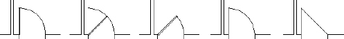
FIGURE 4.39 Possible ways to illustrate pivot doors
Drawing Swinging Doors
The swinging doors are of two widths: 3′ (915 mm) for exterior and 2′-6″ (762 mm) for interior (refer to Figure 4.28 earlier in this chapter). In general, doorway openings leading to the outside are wider than interior doors, with bathroom and bedroom doors usually being the narrowest. For the cabin, you'll use two sizes of swinging doors. If multiple doors of the same width existed in this design, you could draw one door of each size and then copy them to the other openings as required.
To accomplish this, we'll start with the back door (on the left side of the floor plan). The only difference between the back door and the bathroom door is size, so you'll learn how to copy and modify the back door, sizing it to fit the opening for the bathroom. It's a step that far too many AutoCAD users overlook, but taking a moment to develop a basic plan such as this one is certain to help you better understand what you're drawing while making you a more productive user.
Now that we have a plan, let's get started drawing some doors:
- Make sure I04-11-ClosetOpening.dwg (M04-11-ClosetOpening.dwg) is open.
- Check the status bar at the bottom of the screen, and verify that Dynamic Input is enabled (a blue background).
- Turn off the remaining drawing aids (buttons) in the status bar.
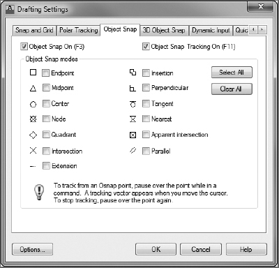
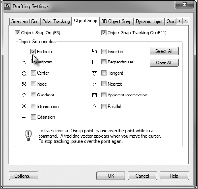
 Right-click the Object Snap button on the status bar, and choose Settings from the context menu.
This opens the Drafting Settings dialog box, and the Object Snap tab is activated (Figure 4.40).
From the Object Snap tab within the Drafting Settings dialog box, click the Clear All button on the right and then click OK.
This step isn't essential, as long as the Object Snap button is turned off, but it's best to be sure in this case. Object snaps are covered in depth in Chapter 5 and are used throughout the remainder of the book.
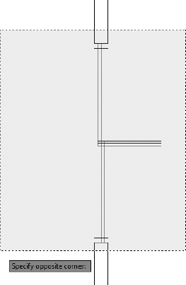
 Launch the Zoom Window tool from the Zoom drop-down menu found on the View tab Navigate 2D panel. Alternatively, you can type Z at the command line or use the Zoom button.
Pick two points to form a window around the back doorway opening, as shown in Figure 4.41 (top).
FIGURE 4.40 The Object Snap tab of the Drafting Settings dialog box
The view changes, and you now have a close-up view of the opening (see Figure 4.41, bottom). You'll draw the door in a closed position and then rotate it open.
You can also start the Rectangle (RECTANG) command by typing REC
at the Type a Command: prompt. To begin drawing the door, use the Rectangle (RECTANG) command from the Home tab Draw panel Rectangle tool.
Notice the Type a Command: prompt in the command-line interface. Several options are in brackets, but the option Specify first corner point (before the brackets) is the default, and it is the one you want. You can also expose these options (see Figure 4.42) at the cursor by pressing the down-arrow on the main keyboard (not the down-arrow on the numeric keypad).
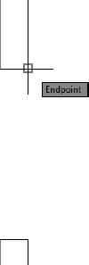
You form the rectangle in the same way that you form the zoom window—by picking two points to represent opposite corners of the rectangle. In its closed position, the door will fit exactly between the jambs, with its two right corners coinciding with the rightmost end-points of the jambs. To make the first corner of the rectangle coincide exactly with the upper-endpoint of the right jamb, you'll use an object snap to assist you.
Object snaps (or osnaps) allow you to pick specific points on objects such as endpoints, midpoints, the center of a circle, and so on. When the Osnap button is active, the cursor will snap to any of the options selected in the Object Snap tab of the Drafting Settings dialog box. These are called running osnaps, and they should be disabled from the status bar at the moment.
Osnap is short for object snap. The two terms are used interchangeably.
FIGURE 4.41 Forming a zoom window at the back door opening (top), and the result (bottom)
Type END
to specify the Endpoint osnap manually.Manually specifying an osnap by entering its name at the command line will override any running osnaps that may be active. For one pick, your cursor will snap to the nearest endpoint of any line, arc, or polyline that you select and ignore any running osnaps such as Midpoint.
FIGURE 4.42 The Rectangle (RECTANG) command options exposed at the cursor
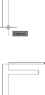
Move the cursor near the right side of the upper jamb line.
When the cursor gets very close to a line, a colored square, called a marker, appears at the nearest endpoint along with a tooltip that indicates which osnap is active, as shown in Figure 4.43. This shows you which endpoint in the drawing is closest to the position of the crosshair cursor at that moment.
FIGURE 4.43 The Endpoint osnap marker
Because of the way AutoCAD displays the crosshair cursor, both the lines and the crosshair disappear when its lines coincide with lines in the drawing. This makes it difficult to see the rectangle being formed.
Move the cursor until the square is positioned on the right end of the upper jamb line as shown, and then click that point.
The first corner of the rectangle now is located at that point. Move the cursor to the right and slightly down to see the rectangle being formed (see Figure 4.44, left). To locate the opposite corner, let's use the relative Cartesian coordinates discussed in Chapter 2.
FIGURE 4.44 The rectangle after picking the first corner (left) and the completed door in a closed position (right)
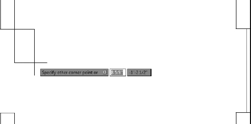
When the command prompt shows the Specify other corner point or [Area/Dimensions/Rotation]: prompt, type −1.5,-3'
(−40,-915 ).The rectangle is drawn across the opening, creating a door in a closed position (see Figure 4.44, right). The door now needs to be rotated around its hinge point to an opened position.
When you used the Rectangle (RECTANG) command to draw the swinging doors, you had to use relative Cartesian coordinates because relative polar coordinates would have required you to know the diagonal distance across the plan of the door and the angle of that distance as well.
Save your drawing as I04-12-SwingingDoor.dwg (M04-12-SwingingDoor.dwg).
Rotating the Door
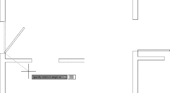
This rotation will be through an arc of 90° in the clockwise direction, making it a rotation of −90°. By default, counterclockwise rotations are positive, while clockwise rotations are negative. You'll use the ROTATE command to rotate the door:
- Continue using I04-12-SwingingDoor.dwg(M04-12-SwingingDoor.dwg), or open it if it's not already open.

Click the Rotate button on the Home tab
Modify panel or type RO. You'll see a prompt to select objects. Click the door and press .You're prompted for a base point—a point around which the door will be rotated. To keep the door placed correctly, pick the hinge point for the base point. The hinge point for this opening is the right endpoint of the bottom jamb line.
- Type END to activate the Endpoint osnap.
- Move the cursor near the lower-right corner of the door. When the marker is displayed at that corner, click to locate the base point.
Check the status bar to be sure the Ortho Mode button isn't pressed. If it is, click it to turn off Ortho (it will change to a gray background).
When the Ortho Mode button is on (with a light blue background), the cursor is forced to move in a vertical or horizontal direction. This is useful at times, but in this instance such a restriction would keep you from being able to see the door rotate.
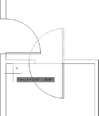
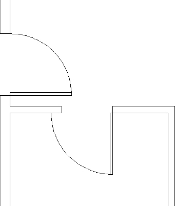
Move the cursor away from the hinge point, and see how the door rotates as the cursor moves (see the left image in Figure 4.45).
FIGURE 4.45 The door rotating with movement of the cursor (left) and the door after the 90° rotation (right)
If the door swings properly, you're reassured that you correctly selected the base point. The prompt in the command line reads Specify rotation angle or [Copy/Reference]<0.00>:, asking you to enter an angle.
- Type −90. The door is rotated 90° to an open position (see the right image in Figure 4.45).
- Save your drawing as I04-13-RotateDoor.dwg (M04-13-RotateDoor.dwg).
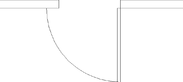
To finish this door, you need to add the door's swing. You'll use the ARC command for this.
Drawing the Door Swing
The swing shows the path that the outer edge of a door takes when it swings from closed to fully open. Including a swing with the door in a floor plan helps to identify the rectangle as a door and helps to resolve clearance issues. You draw the swings by using the ARC command—in this case, using the Endpoint osnap. This command has many options, most of which are based on knowing three aspects of the arc, as you'll see. Here are the steps:
- Continue using I04-13-RotateDoor.dwg (M04-13-RotateDoor.dwg), or open it if it's not already open.
 Click the down-arrow below the Arc button from the Home tab Draw panel.
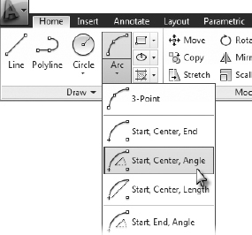
The menu expands to show the 11 methods for creating an arc. On the menu, 10 of the 11 options have combinations of three aspects that define an arc. The arc for this door swing needs to be drawn from the right end of the upper jamb line through a rotation of 90°. You know the start point of the arc, the center of rotation (the hinge point), and the angle through which the rotation occurs, so you can use the Start, Center, Angle option on the Arc menu.
THE OPTIONS OF THE ARC COMMAND
The position and size of an arc can be specified by a combination of its components, some of which are start point, endpoint, angle, center point, and radius. The ARC command gives you 11 options, 10 of which use three components to define the arc. With a little study of the geometric information available to you about your drawing, you can choose the option that best fits the situation.
When you start the ARC command by typing A
, you get an abbreviated form of the command in the command prompt. You can access all 11 options of the command through this prompt, but you have to select the various components along the way.From the expanded Arc menu, choose Start, Center, Angle, as shown in Figure 4.46.
FIGURE 4.46 The expanded Arc menu
The command prompt now reads Specify start point of arc:; this is the default option. You could also start with the center point, but you would have to type C
before picking a point to be the center point.Activate the Endpoint osnap (type END
), and pick the right endpoint of the upper jamb line, as shown in Figure 4.47.FIGURE 4.47 Specifying the start point for the ARC command
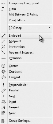
The prompt changes to read Specify second point of arc:. Because you previously chose the Start, Center, Angle option, AutoCAD automatically chooses Center for you as the second point. That is the last part of the prompt. You'll need the Endpoint osnap again, but this time you will pick it from a menu.
- Hold down the Shift key, and right-click in the drawing area to open a context menu containing all the available osnaps.
Click the Endpoint option, as shown in Figure 4.48, to activate the Endpoint osnap.
FIGURE 4.48 Select the Endpoint osnap from the Object Snap context menu.
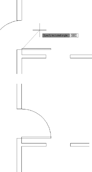
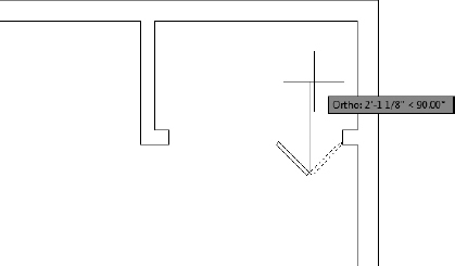
Using the Endpoint osnap, select the hinge point.
The arc is now visible, and its endpoint follows the cursor's movement, but the arc is extending in the wrong direction (see the top image in Figure 4.49). The prompt displays the Specify Included Angle option.
- Type −90. The arc is completed, and the ARC command ends (see the bottom image in Figure 4.49).
Save your drawing as I04-14-DoorSwing.dwg (M04-14-DoorSwing.dwg).
 WARNING: In this situation, the arc must be created by selecting the jamb end first and the door end later. Arcs are made in a counterclockwise fashion, so selecting the door end first and the jamb end later would result in a 270° arc that extends behind the door and through the external wall.
FIGURE 4.49 Drawing the arc: The ending point of the arc follows the cursor's movements (top), and the completed arc (bottom).
The back door is completed. Next you'll copy and then modify the back door to form the bathroom door.
Copying Objects
As you would expect, the COPY command makes a copy of the objects you select. You can locate this copy either by picking a point or by entering relative coordinates from the keyboard. For AutoCAD to position these copied objects, you must designate two points: a base point, which serves as a point of reference for where the copy move starts, and then a second point, which serves as the ending or destination point for the COPY command.
The copy is moved the same distance and direction from its original position that the second point is located from the first point. When you know the actual distance and direction to move the copy, the base point isn't critical because you specify the second point with relative polar or relative Cartesian coordinates. In this situation, however, you don't know the exact distance or angle to move a copy of the back door to the bathroom door opening, so you need to choose a base point for the copy carefully.
In copying this new door and its swing to the back door opening of the cabin, you must find a point somewhere on the existing door or swing that can be located precisely on a point at the back door opening. You can choose from two points: the hinge point and the start point of the door swing. Let's use the hinge point. You usually know where the hinge point of the new door belongs, so this is easier to locate than the start point of the arc. In the following steps, you'll copy the existing door so that it can be used for the bathroom door opening:
- Continue using I04-14-DoorSwing.dwg (M04-14-DoorSwing.dwg), or open it if it's not already open.

Click the Copy button on the Home tab
Modify panel of the Ribbon or type CO at the command line.The prompt asks you to select objects to copy. Pick the door and swing, and then press
.The prompt in the command-line interface reads Specify base point or [Displacement/mOde]<Displacement>:.
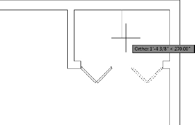
Pick the hinge point by using the Endpoint osnap.
A copy of the door and swing is attached to the crosshair cursor at the hinge point (see Figure 4.50), and the prompt changes to Specify second point or <use first point of displacements>:. You need to pick where the hinge point of the copied door will be located at the bathroom door opening.
Activate the Endpoint osnap once again. This time pick the lower end of the right jamb line on the bathroom door opening.
The copy of the door and swing is placed in the opening (see Figure 4.51).
Looking at the command prompt, you can see that the COPY command is still running, and a copy of both the door and swing remains attached to the cursor.
The COPY command keeps running until you end it. This allows you to make multiple copies of the same object. You'll do that in Chapter 5 when you draw the stovetop.
- Press to end the COPY command.
The door is oriented the wrong way, but you'll fix that next. Save your drawing as I04-15-Copyingobjects.dwg (M04-15-Copyingobjects.dwg).
FIGURE 4.50 The copy of the door and swing attached to the crosshair cursor
FIGURE 4.51 The door is copied to the bathroom door opening.
When you copy doors from one opening to another, the orientation often doesn't match. The best strategy is to use the hinge point as a point of reference and place the door where it needs to go, as you just did. Then flip or rotate the door so that it sits and swings the right way. The flipping of an object is known as mirroring.
Mirroring Objects
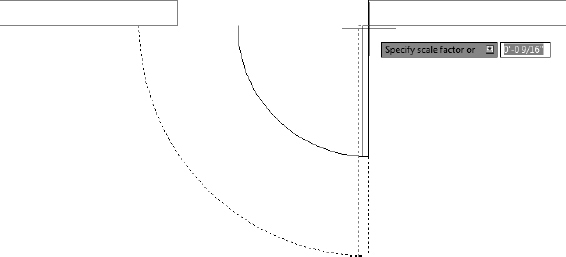
You have located the door in the opening, but it needs to be rotated 90° to be perpendicular to the wall and then flipped so that it swings to the inside of the bathroom. To do this, you'll use the ROTATE command that you used earlier and then the MIRROR command.
The ZOOM command is usable while the COPY command is active. Similarly, most display commands (ZOOM, PAN, and so on) share this functionality and are known as transparent commands.
The MIRROR command allows you to flip objects around an axis called the mirror line. You define this imaginary line by designating two points on the line. Strategic selection of the mirror line ensures the accuracy of the mirroring action. Thus, it's critical to visualize where the proper line lies. Sometimes you'll have to draw a guideline in order to designate one or both of the endpoints.
- Continue using I04-15-CopyingObjects.dwg (M04-15-CopyingObjects.dwg), or open it if it's not already open.
- Click the Rotate button found on the Home tab Modify panel, and select the door and swing for the bathroom door. With the door and swing selected, press .
- Activate the Endpoint osnap by typing END and then picking the hinge point from the Specify base point: prompt.
At the Specify rotation angle: prompt, type 90
.The door is rotated 90°, but its orientation is incorrect, as shown in Figure 4.52.

Start the MIRROR command from the Home tab
Modify panel Mirror tool button, or type MI at the command line. Select the bathroom door and swing, and then press . The prompt line changes to read Specify first point of mirror line:.Try typing P
at the Select Objects: prompt to quickly reselect the last objects selected.Activate the Endpoint osnap, and then pick the hinge point of the door.
The prompt changes to read Specify second point of mirror line:, and you'll see the mirrored image of the door and the swing moving as you move the cursor around the drawing area. You're rotating the mirror line about the hinge point as you move the cursor. As the mirror line rotates, the orientation of the mirrored image changes (see Figure 4.53).
FIGURE 4.52 The door after rotating it 90°
FIGURE 4.53 The mirror image changes as the mirror line rotates.
Press and hold the Shift key to enable Ortho mode temporarily.
A small icon displays in the upper-right quadrant of your cursor to indicate that Ortho mode is temporarily enabled, locking your cursor to increments of 90°.
With the Shift key pressed, select any point to the left, as shown in Figure 4.54.
FIGURE 4.54 Using the Shift key to enable Ortho mode temporarily to pick the mirror line
Activating the temporary Ortho mode override may take a moment. You'll know the override is enabled when the small shield icon appears next to your cursor. Because Ortho mode locks your cursor to rotation increments of 90°, you don't have to be precise when selecting the second point. You can see that the point selected in Figure 4.54 is not perpendicular; however, Ortho mode ensures that the mirror line is drawn along the horizontal bathroom wall.
Type Y
, or select Yes when the command prompt reads Erase source objects? [Yes/No] <N>:.The flipped door is displayed, and the original one is deleted (see Figure 4.55). The MIRROR command ends.
FIGURE 4.55 The mirrored door and swing
- Save your drawing as I04-16-Mirroringobjects.dwg (M04-16-Mirroringobjects.dwg).

It may take some practice to become proficient at visualizing and designating the mirror line, but once you're used to it, you'll have learned how to use a powerful tool. Because many objects—including building layouts, mechanical parts, steel beams, road cross-sections, and so on—have some symmetry to them, wise use of the MIRROR command can save you a lot of drawing time.
Now let's change the scale of the interior to match the available opening.
Scaling the Bathroom Door
You could have used the STRETCH command to make the door narrower, but that's an advanced Modify command and won't be introduced until Chapter 11, “Working with Hatches, Gradients, and Tool Palettes.” Besides, the arc would have to be modified to a smaller radius. It's easier to scale the objects, and the slightly thinner door can be attributed to interior doors being thinner than exterior doors. In Chapter 9, “Using Dynamic Blocks and Tables,” I'll demonstrate a dynamic block that can serve as a door block for several door sizes.
For this exercise, you will use the SCALE command to resize the bathroom door to fit the existing opening. The SCALE command changes the size of all the selected objects by an equal amount based on keyboard input or the location of the cursor. The objects scale up or down in relation to their position relative to a base point you've defined. Objects scaled up will appear to get farther away from the base point, while objects scaled down will appear to get closer.
The 30″ (762 mm) bathroom door opening is ![]() the size of the 30″ (915 mm) back door opening; therefore,
the size of the 30″ (915 mm) back door opening; therefore, ![]() , or its decimal equivalent of 0.8333, can be used as the scale factor. Because fractions are inherently more accurate than rounded-off decimal values, we'll use the fractional scale factor:
, or its decimal equivalent of 0.8333, can be used as the scale factor. Because fractions are inherently more accurate than rounded-off decimal values, we'll use the fractional scale factor:
The scale factor ![]() was derived by reducing
was derived by reducing ![]() . Because a 762 mm door isn't exactly
. Because a 762 mm door isn't exactly ![]() of a 915 mm door, the unreduced fraction
of a 915 mm door, the unreduced fraction ![]() can be substituted to achieve an accurate scale factor.
can be substituted to achieve an accurate scale factor.
- Continue using I04-16-MirroringObjects.dwg (M04-16-MirroringObjects.dwg), or open it if it's not already open.
Click the Zoom Window button found on the navigation bar to zoom in to the interior door opening (see Figure 4.56).
FIGURE 4.56 A close-up view of the bathroom door

Start the SCALE command by using the Scale button found on the Home tab
Modify panel, or type SC at the command line.- At the Select objects: prompt, select the bathroom door and swing, and then press .
At the Specify base point: prompt, type END
and pick the hinge point.As you move the cursor, you can see the scaled version of the door change size depending on how far the cursor is located from the base point (see Figure 4.57).
FIGURE 4.57 Using the Scale tool to resize the bathroom door
Type 5/6
(762/915) to scale the 36″ (915 mm) door down to 30″ (762 mm).The rescaled door should look like Figure 4.58.
FIGURE 4.58 The rescaled bathroom door
- Save your drawing as I04-17-ScalingObjects.dwg (M04-17-ScalingObjects.dwg).
As you can see, as long as you know the scale factor, it's easy to use the SCALE command to resize objects in your drawing. The next door to draw is the sliding glass door. This kind of door requires an entirely different strategy, but you'll use commands familiar to you by now.
Drawing a Sliding Glass Door
You will need to use the Endpoint osnap a lot while creating, copying, rotating, and mirroring objects; it's probably the most frequently used of the osnaps. Rather than activating it as needed, you will turn on Endpoint as a running osnap—an osnap that is permanently turned on:
- Continue using I04-17-Scalingpbjects.dwg (M04-17-ScalingObjects.dwg), or open it if it's not already open.
- Right-click the Object Snap button in the status bar, and then select the Settings option in the context menu.
In the Object Snap tab of the Drafting Settings dialog box, select the Endpoint check box.
While the cursor is near the selection, a tooltip appears, describing the features to which the osnap moves the cursor. Take a moment to investigate what each of the osnap options does before clicking the OK button (see Figure 4.59).
FIGURE 4.59 The Object Snap tab of the Drafting Settings dialog box
- The osnap is active, but the running osnaps are not turned on. Click the Object Snap button to turn on (light blue background) running osnaps. Now whenever you are prompted to pick a point, a marker will appear over the nearest endpoint of the object the cursor is over.
Sliding glass doors are usually drawn to show their glass panels within the door frames, as shown in Figure 4.60.
FIGURE 4.60 A common appearance for a sliding glass door
To draw the sliding door, you'll apply the LINE, OFFSET, and TRIM commands to the 7′ (2134 mm) opening you made earlier. It's a complicated exercise, but it will teach you a lot about the power of using these three commands in combination:
- Continue using 104-17-ScalingObjects.dwg (M04-17-ScalingObjects.dwg), or open it if it's not already open.
- Zoom out by rolling the mouse wheel toward you or by using the Zoom Extents (ZOOM) command. Zooming with the mouse wheel zooms the drawing toward or away from the location of the cursor.
Zoom closely around the 7′ (2134 mm) opening.
Try zooming with the scroll wheel by placing the cursor in the center of the opening and rolling the scroll wheel away from you. Make the opening as large as possible while including everything you need in the view (see Figure 4.61).
You'll be using several osnaps for this procedure. Rather than entering each osnap, you can activate any object snap by holding down the Shift key and right-clicking in the drawing area. This opens a context menu with all of the object snap options shown earlier in Figure 4.50. Selecting any of these options activates the osnap for a single pick.
Using the ZOOMFACTOR variable, you can control how quickly rolling the mouse wheel zooms your drawing. Type ZOOMFACTOR
and, when prompted, enter a value between 3 and 100. Lower values perform slower zooms, and vice versa.You probably noticed the list of osnaps that appeared when you right-clicked the Object Snap button in the status bar. These do not activate an osnap for a single pick; rather, they are a quick method for activating or deactivating a running osnap.
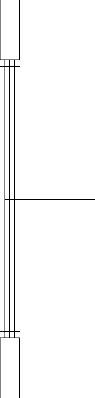
Offset each jamb line 2″ (51 mm) into the doorway opening (see Figure 4.62).
FIGURE 4.61 The view when zoomed in as closely as possible to the 7′ (2134 mm) opening
FIGURE 4.62 Jamb lines offset 2″ (51 mm) into the doorway opening
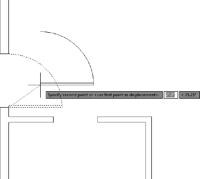
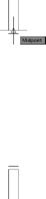
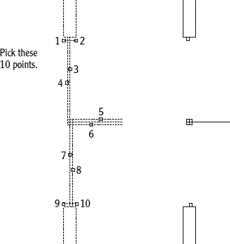
 Start the LINE command, and choose the Midpoint osnap from the Shift+right-click context menu.
Place the cursor near the midpoint of the upper doorjamb line and notice that the marker, now a triangle, appears when your cursor is in the vicinity of the midpoint (see Figure 4.63).
FIGURE 4.63 Using the Midpoint osnap to select the start point of the line
A symbol with a distinctive shape is associated with each osnap. Click when the triangle appears at the midpoint of the jamb line.
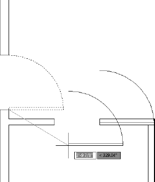
Move the cursor over the bottom jamb line, and you'll notice the Endpoint markers appear.
The Endpoint running osnap is still active, but typing in the first three letters of an osnap or clicking an osnap option from the context menu overrides it.
- Click the Midpoint osnap option again, and move the cursor to the bottom jamb line.
- When the triangle appears at that midpoint, click again. Press to end the LINE command.
- Start the OFFSET command, and enter 1.5 (38) to set the offset distance.
- Pick the newly drawn line, and then pick a point anywhere to the right side.
While the OFFSET command is still running, pick the original line again and pick another point in a blank area somewhere to the left side of the doorway opening (see Figure 4.64).
FIGURE 4.64 The offset vertical lines between the jambs
- Press to end the OFFSET command.
 In the status bar, click the Ortho Mode button to turn that mode on (light blue background). Ortho mode restricts the cursor to vertical and horizontal movements only.
Start the LINE command, choosing the Midpoint osnap option, and then move the cursor near the midpoint of the left vertical line.
When the triangle marker appears at the midpoint, click to set the endpoint of the line.
Hold the cursor out directly to the right of the point, which you just selected to draw a horizontal line through the three vertical lines.
When the cursor is about 2′ (600 mm) to the right of the three vertical lines, pick a point to set the endpoint of this guideline (see Figure 4.65). Press
to end the LINE command. Click Ortho mode off (gray background).FIGURE 4.65 The horizontal guideline drawn through vertical lines
- Type O or click Offset on the Home tab Modify panel to start the OFFSET command, and then type 1 (25) to set the offset distance to 1″ (25 mm).
Select the horizontal line you just drew, and then pick a point in a blank area anywhere above the line. Pick the first horizontal line again, and then pick anywhere below it.
The new line has been offset 1″ (25 mm) above and below itself (see Figure 4.66). Now you have placed all the lines necessary to create the sliding glass door frames in the opening. You still need to trim back some of these lines and erase others. Press
to end the OFFSET command. Start the TRIM command. When you're prompted to select cutting edges, pick the two horizontal lines that were just created with the OFFSET command and press .
- Trim the two outside vertical lines by selecting them, as shown on the left of Figure 4.67. The result is shown on the right.
Press
twice to stop and restart the TRIM command.FIGURE 4.66 The offset horizontal guideline
FIGURE 4.67 Picking the vertical lines to trim (left), and the result (right)
When you're prompted to select cutting edges, use a special window called a crossing window to select all the lines visible in the drawing.
A crossing window selects everything within the window or crossing it. See the sidebar titled “Understanding Selection Windows” later in this chapter for additional information about this feature. Here's how to use a crossing window:
- Pick a point above and to the right of the opening.
Move the cursor to a point below and to the left of the opening, forming a semitransparent green-colored window with dashed boundary lines (see Figure 4.68).
FIGURE 4.68 The crossing window for selecting cutting edges
- Pick that point. Everything inside the rectangle or crossing an edge of it is selected.
- Press .
To trim the lines, pick them at the points noted on the left of Figure 4.69.
When you finish trimming, the opening should look like the right side of Figure 4.69. Be sure to press
to end the TRIM command.FIGURE 4.69 Lines to trim (left) and the result (right)
Start the ERASE command, and erase the remaining horizontal guideline.
To finish the sliding glass doors, you need to draw two lines to represent the glass panes for each door panel. Each pane of glass is centered inside its frame, so the line representing the pane will run between the midpoints of the inside edge of each frame section.
ADJUSTING TRIM WITH THE EDGEMODE SYSTEM VARIABLE
If all the lines don't trim as you would expect, you may have to change the setting for the EDGEMODE system variable. Cancel the trim operation, and undo any trims you've made to the sliding glass door. Type EDGEMODE
and then type 0. Now start the TRIM command and continue trimming.EDGEMODE controls how the TRIM and EXTEND commands determine cutting edges. When set to its default value of 0, EDGEMODE uses the selected edge without any extensions. When set to 1, EDGEMODE extends or trims the selected object to an imaginary extension of the cutting or boundary edge.
- Start the LINE command. Hold down the Shift key, right-click, and then select the Midpoint osnap option from the context menu.
For each of the two sliding door frames, draw a line from the midpoint of the inside frame (nearest the jamb) to a point perpendicular to the frame section in the middle. To do this, follow these steps:
- Place the cursor near the midpoint of the inside line of the frame section nearest the jamb. When the colored triangle appears there, click.
- Type PER or click the Perpendicular osnap from the Object Snap context menu, and move the cursor to the other frame section of that door panel.
- When you get near the horizontal line that represents both the inside edge of one frame section and the back edge of the frame section next to it, the colored Perpendicular osnap marker will appear on that line, as shown in Figure 4.70. When it does, select that point.
FIGURE 4.70 Using the Perpendicular osnap to set the endpoint of the line
- Press to end the LINE command.
Press
to restart the LINE command, and repeat the procedure described in steps 25 through 27 for the other door panel, being sure to start the line at the frame section nearest the other jamb. The finished opening should look like Figure 4.71.FIGURE 4.71 The finished sliding glass doors
- Save your drawing as I04-18-SlidingGlassDoor.dwg (M04-18-SlidingGlassDoor.dwg).
Drawing the Bifold Doors
Bifold doors are generally shown with each door in a half-open position to indicate their distinctive design. Although there are four door panels on the cabin's closet door, you will need to draw only one, rotate it into place, and then create copies with the MIRROR command. To begin the exercise, you will use the PAN command to shift the view of your drawing to see the closet area without changing the zoom factor. Here is how you do it:
Continue using I04-18-SlidingGlassDoor.dwg (M04-18-SlidingGlassDoor.dwg), or open it if it's not already open.
Start the PAN command from the View tab
Navigate 2D panel, click the Pan button, or type P at the command line. The cursor changes appearance to look like an open hand.
- Place the cursor near the upper jamb of the sliding glass door, and then click and drag the mouse downward until the drawing area shifts to display the closet area (see Figure 4.72).
FIGURE 4.72 Pan the view to show the closet area.
Press the Esc key to end the PAN command, or right-click and choose Exit from the context menu.
The closet opening is 4′ (1220 mm) wide, so you will need to make four door panels, each 1′ (305 mm) wide.
As an alternative to using the PAN command, you can simply hold down the scroll wheel and drag to use the pan function transparently—without exiting an active command.
- Start the Rectangle (RECTANG) command and specify the lower corner of the right closet jamb as the first corner point. The running Endpoint osnap ensures that the corner point is selected precisely.
Type −1,-12
(−25,-305) to create a rectangle 1″ (25 mm) wide and 12″ (305 mm) long oriented toward the bottom of the cabin, as shown in Figure 4.73.FIGURE 4.73 The first closet door panel is drawn.
NOTE: It should be clear by now that, when a command allows multiple picks in order to select several objects, you need to press to terminate the selection process and proceed with the command. From now on, when you are directed to select an object(s), I won't tell you to press to end the selection process.Type −45
. The door rotates 45° (see Figure 4.74), and the ROTATE command ends.FIGURE 4.74 The first closet door panel is rotated.
- Start the MIRROR command from the Home tab Modify panel, and then select the closet door panel.
- Verify that Ortho mode is still turned on in the status bar. If it's not, click the Ortho Mode button or press the F8 shortcut key to turn on Ortho mode.
- At the Specify first point of mirror line: prompt, click the far-left corner point of the selected panel.
- Move the cursor either up or down until you see the mirror door panel directly to the left of the first panel (see Figure 4.75); then click to specify the second point of the mirror line.
- Press to accept the default No option when prompted to erase the source object.
Start the MIRROR command again, and this time select both of the door panels.
FIGURE 4.75 Mirroring the first closet door panel
- Choose the midpoint of the back wall of the closet as the first point of the mirror line.
Then move the cursor downward to mirror the existing panels directly to the left, as shown in Figure 4.76.
FIGURE 4.76 The closet door is complete.
- Click to set the second point, and then press to retain the source objects.
- Click the Zoom Extents button to see the full floor plan with all doors (see Figure 4.77).
- Save this drawing as I04A-FPLAYO.dwg (M04A-FPLAYO.dwg).
UNDERSTANDING SELECTION WINDOWS
In addition to selecting objects by using a direct pick, you can select objects by using a rectangular selection window. To use a selection window at any Select objects: prompt, pick a point at a blank spot in the drawing area to define one corner of the window and then a second point to define the opposite corner.
Selection windows come in two styles: windows and crossing windows. When you use a window selection, all objects must be entirely inside the boundary of the window to be selected. When you use a crossing window, all objects entirely within the boundary as well as any objects that cross the boundary are selected. AutoCAD distinguishes the two types of selection windows visually. Window selection areas are transparent blue and have solid boundary lines, and crossing windows are transparent green with dashed boundary lines.
By default, window selections are used when the boundary is created from left to right, and crossing selections are used when the boundary is created from right to left. By typing W![]() or C
or C![]() at the Select objects: prompt, you can override the direction default or create a selection window even when the mouse is clicked as the cursor is over an object.
at the Select objects: prompt, you can override the direction default or create a selection window even when the mouse is clicked as the cursor is over an object.
Selection windows can even be used to select objects to be trimmed or extended. For instance, visualize a horizontal line with dozens of vertical lines crossing it, and each of those lines must be trimmed back to the horizontal line. After designating the horizontal line as the cutting edge, use a crossing selection window to select all of the vertical lines on the trim side. All the lines are trimmed with two picks instead of many.
![]()
To change settings that control the appearance of the crossing and regular selection windows, open the Application menu and click the Options button in the lower-right corner, or type OP![]() at the command line.
at the command line.
Click the Selection tab of the Options dialog box and then, in the Selection Preview area, click the Visual Effect Settings button, as shown in Figure 4.78.
In the Visual Effect Settings dialog box that opens (see Figure 4.79), you'll see settings in the Area Selection Effect section for controlling whether the selection windows have color in them, which color will be in each window, and the percentage of transparency of the colors. The left side of the dialog box controls the appearance of an object's highlighting when the cursor hovers over it. Experiment with different settings. Click OK twice to return to your drawing, and test the windows to see how they look.
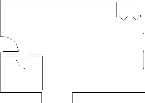
FIGURE 4.77 The cabin with the walls and doors completed
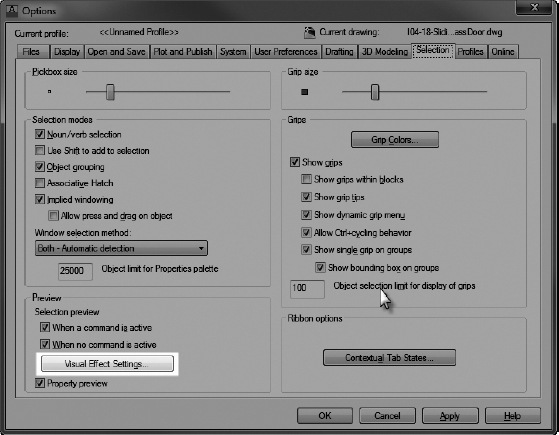
FIGURE 4.78 Click the Visual Effect Settings button.
This completes the doors for the floor plan. The focus here has been on walls and doors and the strategies for drawing them. As a result, you now have a basic floor plan for the cabin, and you'll continue to develop this plan in the next chapter.
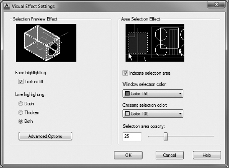
FIGURE 4.79 The Visual Effect Settings dialog box
The overall drawing strategy emphasized in this chapter uses objects already in the drawing to create new ones. You started with several lines that constituted the outside wall lines. By offsetting, extending, and trimming, you drew all the walls and openings without drawing any new lines. For the swinging doors, you made a rectangle and an arc. Then by copying, rotating, and mirroring, you formed the other swinging door. For the sliding glass door, you drew two new lines and used OFFSET, TRIM, and ERASE to finish the door. Therefore, you used four lines and created six new objects to complete the walls and doors. This is a good start in learning to use AutoCAD efficiently.
Throughout this chapter, I have indicated several instances when you can press the spacebar instead of the ![]() key. This can be handy if you keep one hand resting on the keyboard while the other hand controls the mouse. For brevity, I'll continue to instruct you to use
key. This can be handy if you keep one hand resting on the keyboard while the other hand controls the mouse. For brevity, I'll continue to instruct you to use ![]() and not mention the spacebar, but as you get better at drawing in AutoCAD, you may find the spacebar a useful substitute for
and not mention the spacebar, but as you get better at drawing in AutoCAD, you may find the spacebar a useful substitute for ![]() in many cases. You'll determine your preference. You can substitute the spacebar for
in many cases. You'll determine your preference. You can substitute the spacebar for ![]() when handling the following tasks:
when handling the following tasks:
- Restarting the previous command
- Ending a command
- Moving from one step in a command to the next step
- Entering a new offset distance or accepting the current offset distance
- Entering relative or absolute coordinates
- Entering an angle of rotation
After working with the tools and strategies in this chapter, you should have an idea of an approach to drawing many objects. In the next chapter, you'll continue in the same vein, learning a few new commands and strategies as you add steps, a balcony, a kitchen, and a bathroom to the floor plan.
If You Would Like More Practice…
If you would like to practice the skills you have learned so far, here are some extra exercises.
An Alternative Sliding Glass Door
Here is a simplified version of the sliding glass door of the cabin, as shown in Figure 4.80. This version doesn't include any representation of the panes of glass and their frames.
FIGURE 4.80 An alternative to the sliding glass door
To draw it, use a technique similar to the one described in the previous section. Copy the jambs for the 7′ (2134 mm) opening to the right, and draw this door between them.
An Addition to the Cabin
This addition is connected to the cabin by a sidewalk and consists of a remodeled two-car garage in which one car slot has been converted into a storage area and an office (see Figure 4.81). Use the same commands and strategies you have been using up to now to draw this layout adjacent to the cabin. Save this exercise as 04A-FPGARG.dwg.
Refer to this chapter and the preceding one for specific commands. Here is the general procedure:
- Draw the outside exterior wall lines.
- Use OFFSET, FILLET, and TRIM to create the rest of the walls and wall lines.
- Use OFFSET, EXTEND, and TRIM to create the openings.
- Use RECTANG and ARC to create a swinging door.
- Use COPY, ROTATE, and MIRROR to put in the rest of the doors.
- Use OFFSET, LINE, and COPY to draw the storage partitions.
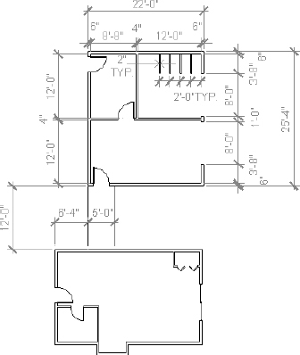
FIGURE 4.81 The garage addition
Three Views of a Block
Use the tools you have learned in the last few chapters to draw the top, right side, and front views of the block shown in Figure 4.82.
Figure 4.83 gives you a graphic representation of the 12 steps necessary to complete the exercise.
Here are the 12 steps in summary that correspond to the 12 drawings. Start with the top view:
- Start a new drawing. Leave all settings at the defaults. Use relative polar or relative Cartesian coordinates and the LINE command to draw a rectangle 17.75 units wide and 11.51 units high. Zoom out if necessary.
Offset the bottom horizontal line up 2.16 units and the new line up 4.45 units.
FIGURE 4.82 The block
FIGURE 4.83 The 12 steps for creating the block
- Offset the right vertical line 4.75 units to the left and the new line 3.50 units to the left.
Use the TRIM command to trim back lines and complete the view.
Next, draw the right side view:
- Draw a vertical line to the right of the top view. Make it longer than the top view is deep.
- Offset the vertical line 2.4 units to the right, and then offset the new line 2.4 units to the right also.
- Use the Endpoint osnap to draw lines from the corner points of the top view across the three vertical lines.
Trim the lines back to complete the side view.
Finally, draw the front view:
- Draw a horizontal line below the top view. Make it longer than the top view is wide.
- Offset this line 2.4 units down, and then offset the new line 2.4 units down.
- Use the Endpoint osnap to draw lines from the corner points of the top view, down across the three horizontal lines.
- Trim the lines back to complete the view.
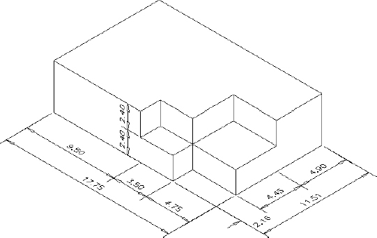
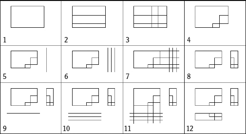
This ends the exercise. You can rotate and move each view relative to the other views in several ways. You'll look at those commands later in the book and then draw more views in Chapter 8.
Are You Experienced?
Now you can…
- Create polylines
- Offset exterior walls to make interior walls
- Zoom in on an area with the Zoom Window (ZOOM) command and zoom back out with the Zoom Previous (ZOOM) command
- Use the Rectangle (RECTANG) and ARC commands to make a door
- Use the Endpoint, Midpoint, and Perpendicular object snap modes
- Use the crossing window selection tool
- Use the COPY and MIRROR commands to place an existing door and swing in another opening
- Use the OFFSET and TRIM commands to make a complex assembly
- Begin drawing 2D representations of 3D shapes