
CHAPTER 7
Combining Objects into Blocks
Much of the efficiency of computer drafting is derived from a feature that makes it possible to combine a collection of objects into an entity that behaves as a single object. In the Autodesk® AutoCAD® software, these collected objects are called a block. The AutoCAD tools that work specifically with blocks make it possible to do the following:
- Create a block in your current drawing
- Repeatedly place copies of a block in precise locations in your drawing
- Share blocks between drawings
- Create DWG files from either blocks or portions of your current drawing
- Store blocks on a palette for easy reuse in any drawing
In general, objects that are best suited to becoming part of a block are the components that are repeatedly used in your drawings. In architecture and construction, examples of these components are doors, windows, and fixtures; or drawing symbols, such as a North arrow; or labels for a section cut line (examples of which are shown in Figure 7.1 in the first section of this chapter). In mechanical drawings, these can be countersunk and counter-bored holes, screws, bolts, fasteners, switches, or any other objects that you find yourself repeatedly drawing. In your cabin drawing, you'll convert the doors with swings into blocks. You'll then create a new block that you'll use to place the windows in the cabin drawing. To accomplish these tasks, you need to learn two new commands: BLOCK and INSERT.
In this chapter, you will learn to
- Create, insert, and export blocks
- Detect blocks in a drawing
- Insert and manage blocks using the Design Center and tool palettes
Making a Block for a Door
When making a block, you create a block definition. This is an entity that is stored in the drawing file and consists of the following components:
- The block name
- An insertion point to help you place the block in the drawing
- The objects to be grouped into the block
You specify each of these in the course of using the BLOCK command. When the command is completed, the objects are designated as a single block, and the block definition is stored with the drawing file. You then insert additional copies of the block into the drawing by using the INSERT command.
ABOUT COMMANDS AND TOOLS
In earlier chapters, I told you exactly what to click or enter to launch a command. Now that you're familiar with the AutoCAD interface, I'll simply instruct you to start a command or tool. In general, I'll refer to a command by the tooltip that appears when you place the cursor on the command's icon on the Ribbon or the command as it is entered at the Type a Command: prompt.
I'll refer to tools and commands that do not have an icon on the Ribbon by their name on the associated menu, toolbar, or other interface element such as the status bar. In the rare case that the command doesn't appear in either place, I'll tell you what to enter in the command-line interface. Any command can be started by entering its name or an alias at the Type a Command: prompt, while others have keyboard shortcuts. Where applicable, I'll mention the command aliases and keyboard shortcuts.
Before you create a block, you must consider the layers on which the objects to be blocked reside. When objects on layer 0 are grouped into a block, they take on the color and linetype of the layer that is current when the block is inserted or the layer to which you move the block. Objects on other layers retain the properties of their original layers, regardless of which color or linetype has been assigned to the current layer. This is one characteristic that distinguishes layer 0 from all other layers.
The objects that compose blocks can reside on more than one layer.
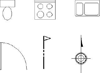
FIGURE 7.1 Examples of blocks often used in architectural drawings
While it's technically possible to create blocks on any layer of your choice, the generally accepted best practice is always to define blocks that are to be used as symbols in a drawing on layer 0. It is also recommended that the color, linetype, and lineweight of each be set to ByLayer or ByBlock. Drawing your blocks with these properties in mind does a number of things.
First and foremost, it helps ensure that, when you insert a block on a given layer, the block functions as if it were drawn on that layer. By using the ByLayer or ByBlock settings, you help avoid the confusion often experienced with colors and linetypes in blocks. This allows the display of blocks to be determined in the same context as the other linework in your drawing in the Layer Properties Manager. Consequently, changes within the Layer Properties Manager apply to blocks the same as they would to other linework in your drawing. In the coming exercises, I'll show you how to follow these best practices while converting some of the objects already in your drawing into blocks and creating some new blocks of your own.
To get started, you'll see how to create blocks from objects already in your drawing. You'll create a block for the back exterior door and call it A-DOOR-36IN to match the NCS naming convention used throughout this book. For the insertion point, you need to assign a point on or near the door that will facilitate its placement as a block in your drawing. The hinge point makes the best insertion point.
For this chapter, the Endpoint osnap should be running most of the time, and Polar Tracking should be off. Follow these steps to set up your drawing:
- Continue using the I06A-FPLAYO.dwg (M06A-FPLAYO.dwg) drawing you created in Chapter 6, “Using Layers to Organize Your Drawing.” If you're starting a new session, you can download this file from the book's website at www.sybex.com/go/autocad2013ner or from www.thecadgeek.com.
- Click the Layer drop-down list, and click the sun icon for the A-WALL-HEAD layer to freeze it.
You're using the Freeze option for layers this time because you won't need to see the lines on the A-ROOF, A-FLOR-FIXT, and A-WALL-HEAD layers for a while. This might be a good time to consider creating another layer state.
- Then click the A-DOOR layer to close the list.
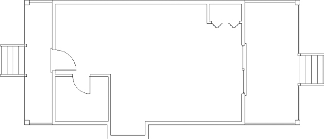
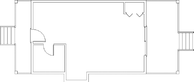
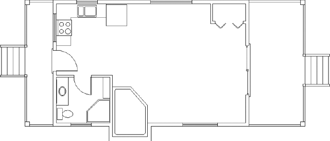
The A-DOOR layer is now current, and the sun next to the A-WALL-HEAD layer turns into a snowflake. In addition to the A-WALL-HEAD layer, the A-FLOR-FIXT and A-ROOF layers should still be frozen from Chapter 6 (see Figure 7.2).
FIGURE 7.2 The floor plan with the A-FLOR-FIXT, A-ROOF, and A-WALL-HEAD layers frozen
- Check the status bar, and make sure the Object Snap button is in the On position.
- Right-click the Object Snap button to display the Object Snap tab inside the Drafting Settings dialog box.
- Make sure that, at a minimum, the Endpoint osnap is running. If it isn't, select the Endpoint Object Snap check box in the Drafting Settings dialog box.
- In the status bar, turn Polar Tracking off if it's on.
- Turn off Quick Properties to prevent the Quick Properties panel from opening whenever an object is selected.
Now you're ready to make blocks:
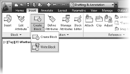
 Click the Create Block button found on the Insert tab
  Block create Definition panel.
You can also start the BLOCK command by entering B
 .
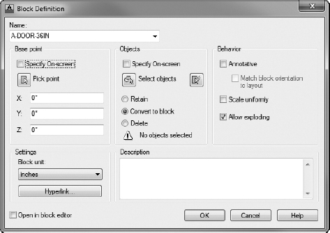
.The Block Definition dialog box opens, where you can specify some basic parameters about your block.
- Notice the flashing cursor in the Name text box. Type A-DOOR-36IN (A-DOOR-0915), but don't press
 (see Figure 7.3).
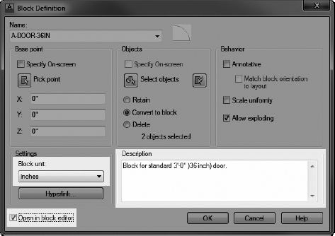
FIGURE 7.3 The Block Definition dialog box
 Click the Pick Point button in the Base Point group of the Block Definition dialog box.
The dialog box temporarily closes, and you're returned to your drawing.
- Use the scroll wheel on the mouse to zoom in to the back door area in your drawing.
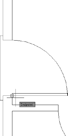
- Move the cursor to the back door area, and position it near the hinge point of the door. When the Endpoint marker appears on the hinge point (see Figure 7.4), click.
FIGURE 7.4 The back door opening when the hinge point is picked as the insertion point
This selects the insertion point for the door, and the Block Definition dialog box returns. The insertion point is the location, relative to the cursor, that the block references when it is inserted.
 Click the Select Objects button in the Objects group of the Block Definition dialog box.
You're returned to the drawing again. The cursor changes to a pickbox, and the command-line interface displays the Select objects: prompt.
- Select the door and swing, and then press .
You're returned to the Block Definition dialog box.
- At the bottom of the Objects group, the count of selected objects appears. Just above that are three radio buttons. Click the Delete radio button if it's not already selected.
The Delete option erases the selected objects after the block definition is created, requiring you to insert the block into the drawing.
The Convert To Block option replaces objects with a block definition as soon as the block is created. In this situation, the Convert To Block option would be a better choice, but it's a good idea to get some practice using the INSERT command, so click Delete.
- Enter a description of the block in the Description field, and make sure Inches or Millimeters is specified in the Block Unit drop-down list, depending on the units you are using.
The Block Definition dialog box should look similar to Figure 7.5.
FIGURE 7.5 Defining the A-DOOR-36IN (A-DOOR-0915) settings within the Block Definition dialog box
- At the bottom of the dialog box, be sure the Open In Block Editor check box is selected and then click OK to close the dialog box.
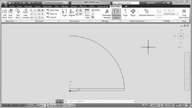
The Block Editor loads, displaying the A-DOOR-36IN (A-DOOR-0915) block you just created (see Figure 7.6).
FIGURE 7.6 The Block Editor displaying the A-DOOR-36IN (A-DOOR-0915) block
Because the objects, in this case the door and swing, used to create the A-DOOR-36IN (A-DOOR-0915) block were drawn on the A-DOOR layer, the objects within the block are also on that layer. As discussed earlier, the preferred practice is to define blocks such as this one on layer 0 so that they're easier to manage.
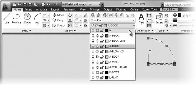
- Select the door and swing inside the Block Editor, and change its layer to layer 0 by using the Layer drop-down on the Home tab Layers panel (see Figure 7.7).
FIGURE 7.7 Changing the door's layer inside the Block Editor
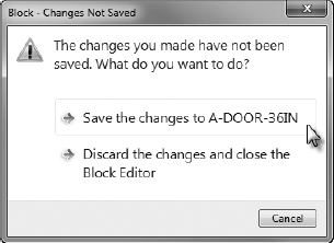
- Click the Close Block Editor button found on the contextual Close panel appended to the end of any Ribbon tab.
- If prompted, choose Save The Changes To A-DOOR-36IN (A-DOOR-0915) from the Block – Changes Not Saved dialog box, as shown in Figure 7.8.
FIGURE 7.8 Choosing to save changes from the Block – Changes Not Saved dialog box
- Save your drawing as I07-01-DoorBlock.dwg (M07-01-DoorBlock.dwg) by choosing Application menu Save As AutoCAD Drawing.
You have now created a block definition called A-DOOR-36IN (A-DOOR-0915). Block definitions are stored electronically with the drawing file. You need to insert the A-DOOR-36IN (A-DOOR-0915) block (known formally as a block reference) into the back door opening to replace the door and swing that were just deleted when the block was created.
Inserting the Door Block
You'll use the INSERT command to place the A-DOOR-36IN (A-DOOR-0915) block back into the drawing:
 Make sure I07-01-DoorBlock.dwg (M07-01-DoorBlock.dwg) is open, and set the A-DOOR layer as the current layer.
- Click the Insert button found on the Insert tab Block panel.
This opens the Insert dialog box, where you will choose the block you would like to insert into your drawing.
- From the Insert dialog box, choose the A-DOOR-36IN (A-DOOR-0915) block by using the Name drop-down list found at the top of the dialog box.
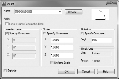
A preview of the block appears in the upper-right corner (see Figure 7.9). Below the Name list are three groups with the Specify On-Screen option. These are used for the insertion procedure.
FIGURE 7.9 The Insert dialog box
- With the A-DOOR-36IN (A-DOOR-0915) block specified, choose the following settings within the Insert dialog box:
- Under the Insertion Point group, check the Specify On-Screen option.
- Under the Scale group, uncheck the Specify On-Screen option.
- Under the Rotation group, check the Specify On-Screen option.
- Make sure the Explode check box in the lower-left corner is unchecked. Explode disassembles the block into its component parts upon insertion into the drawing.
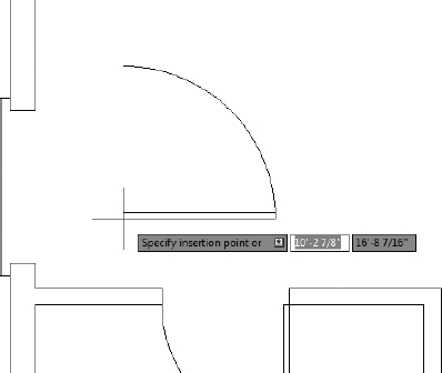
- Click OK to return to your drawing. The A-DOOR-36IN (A-DOOR-0915) block is now attached to the cursor, with the hinge point coinciding with the intersection of the crosshairs (see Figure 7.10).
The command line reads Specify insertion point or [Basepoint/Scale/X/Y/Z/Rotate]:.
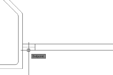
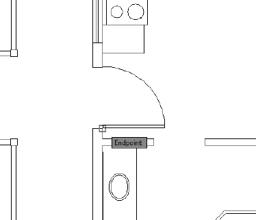
- With the Endpoint osnap running, move the cursor toward the right end of the lower jamb line in the back door opening.
- When the Endpoint marker appears at the jamb line's lower-right endpoint, click.
FIGURE 7.10 The A-DOOR-36IN (A-DOOR-0915) block attached to the cursor
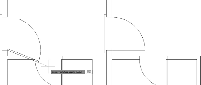
The A-DOOR-36IN (A-DOOR-0915) block is no longer attached to the cursor, and its insertion point has been placed at the right end of the lower jamb line. The block now rotates as you move the cursor (see the left of Figure 7.11).
FIGURE 7.11 The rotation option (left) and the final placement (right)
- At the Specify rotation angle <0.00>: prompt, press again to accept the default angle of 0.
The A-DOOR-36IN (A-DOOR-0915) block properly appears in the drawing (see the right of Figure 7.11).
- Save your drawing as I07-02-BlockInsert.dwg (M07-02-BlockInsert.dwg) by choosing Application menu Save As Drawing.
Each time a block is inserted, you can specify the following on the screen or in the Insert dialog box:
- The location of the insertion point of the block
- The X and Y scale factors
- The Z scale factor in the dialog box (used for 3D drawings, in AutoCAD only)
- The rotation angle
As you insert blocks, you can stretch or flip them horizontally by specifying a negative X scale factor, or vertically by specifying a negative Y scale factor—or you can rotate them from their original orientations. Because you created the A-DOOR-36IN (A-DOOR-0915) block from the door and swing that occupied the back door opening, and the size was the same, inserting this block back into the back door opening required no rotation, so you followed the defaults. You can insert the same block into the back door opening and flip the door horizontally by flipping the Y scale factor. This technique has been largely superseded by the use of dynamic blocks, discussed later in this chapter and in Chapter 9, “Using Dynamic Blocks and Tables,” so I won't demonstrate it in this book.
Nothing has changed about the geometry of the door, but it's now a different kind of object. It was a rectangle and an arc; now it's a block reference comprising a rectangle and an arc.
Doors are traditionally sorted into four categories, depending on which side the hinges and doorknob are on and which way the door swings open. To be able to use one door block for all openings of the same size, you need to know the following:
- How the door and swing in the block are oriented
- Where the hinge point is to be located in the next opening
- How the block has to be flipped and/or rotated during the insertion process to fit properly in the next doorway opening
Blocking and Inserting the Interior Door
Because the interior door is smaller, you need to make a new block for it. You could insert the A-DOOR-36IN (A-DOOR-0915) block with a ![]() scale factor, but this would also reduce the door thickness by the same factor, and you don't want that.
scale factor, but this would also reduce the door thickness by the same factor, and you don't want that.
On the other hand, for consistency, it's a good idea to orient all door blocks the same way, and the bathroom door is turned relative to the A-DOOR-36IN (A-DOOR-0915) block. You'll move and rotate the bathroom door and its swing to orient it like the back door:
- Make sure I07-02-BlockInsert.dwg (M07-02-BlockInsert.dwg) is open.
After you finish the swinging doors, I'll go into some detail about the AutoCAD dynamic block, which you can use for all swinging doors.
- Use Zoom Window to define a window that encloses the bathroom door. The view changes to a close-up of the area enclosed in your window (see Figure 7.12).
FIGURE 7.12 The result of a zoom window
- Repeat a procedure similar to the one you used to make a block out of the back door and swing to make a block out of the bathroom door and swing. Here is a summary of the steps:
- Start the BLOCK command. (Click the Create Block button on the Home tab Block Definition panel.)
- In the dialog box, type A-DOOR-30IN (A-DOOR-0762) to name the new block. Don't press .
- Click the Pick Point button, and pick the hinge point of the bathroom door.
- Click the Select Objects button, and pick the door and swing. Then press .
- In the Objects group, make sure the Delete radio button is selected.
- Make sure the Block Unit option is correct, and add a description.
- Select the Open In Block Editor check box, and then click OK.
The door and swing disappear, and the Block Editor will open to display the block you just created.
- Start the BLOCK command. (Click the Create Block button on the Home tab
- Use the Layer drop-down on the Home tab Layers panel to change the layer of the door and swing to layer 0 from within the Block Editor.
After changing the layer, click Close Block Editor, being sure to save changes.
- Insert the A-DOOR-30IN (A-DOOR-0762) block in the bathroom doorway opening. Follow the steps carefully. Here's a summary:
- Start the INSERT command.
- Open the Name drop-down list, select A-DOOR-30IN (A-DOOR-0762), and then click OK.
- Pick the bottom end of the right jamb line.
- Accept the scale factors of 1 and the default 0 for the rotation.
 NOTE If all your doors are at 90° angles, you can turn on Ortho mode to speed up the rotation process. With Ortho active, wherever you move the cursor at the Specify rotation angle <0.00>: prompt, the rotations are restricted to 90° increments.
 - Use the Zoom Extents tool to show the entire cabin in the drawing area (see Figure 7.13).
FIGURE 7.13 The floor plan with all swinging doors converted into blocks
- Save your drawing as I07-03-InteriorDoor.dwg (M07-03-InteriorDoor.dwg).
![]() TIP If you have trouble anticipating how a block such as the door block needs to be flipped or rotated during insertion, don't worry about it; just be sure to locate the insertion point accurately in the drawing. Then, after the block is inserted, you can flip or turn it by using the MIRROR and ROTATE commands.
TIP If you have trouble anticipating how a block such as the door block needs to be flipped or rotated during insertion, don't worry about it; just be sure to locate the insertion point accurately in the drawing. Then, after the block is inserted, you can flip or turn it by using the MIRROR and ROTATE commands.
This view looks the same as the view you started with at the beginning of this chapter (see Figure 7.2). Blocks look the same as other objects, and you can't detect them by sight. They're useful because you can use them over and over again in a drawing or in many drawings and because the block is a combination of two or more (and sometimes many more) objects represented as a single object. Your next task is to learn how to detect a block, but first I'll discuss the AutoCAD dynamic block feature.
Using Dynamic Blocks
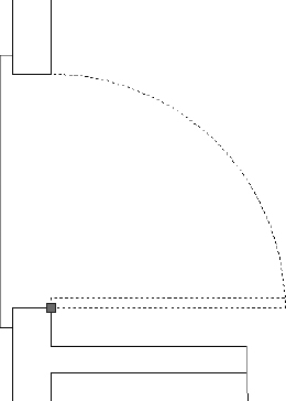
Dynamic blocks are blocks whose appearance can be changed in a variety of ways, depending on how they are set up. Any block can be transformed into a dynamic block, and AutoCAD offers several sample dynamic blocks that have already been set up. Take a door block, for example. By adding extra parameters and controls to the block, you could use a single dynamic block for openings in a variety of preset sizes. The arc size would change, but the thickness of the door would remain the same. After you insert a dynamic block, click it. As shown in Figure 7.14, light-blue arrows (grips) appear at opposite sides of the opening to indicate that these are adjustable parameters. This is just an example and not steps for you to follow at this time. You will have a chance to work with dynamic blocks in Chapter 9.
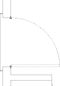
FIGURE 7.14 Arrows appear at the locations in a dynamic block where the parameters are adjustable.
THE FATE OF OBJECTS USED TO MAKE A BLOCK
The three radio buttons in the Objects group of the Block Definition dialog box represent the options you have for objects transformed into a block:
Retain The objects remain unblocked. Click this if you want to make several similar blocks from the same set of objects.
Convert To Block The objects become the block reference. Click this if the first use of the block has geometry identical to that of the set of objects it's replacing.
Delete The objects are automatically erased after the block has been defined. Click this if the first use of the block will be at a different scale, orientation, or location from the set of objects it's replacing.
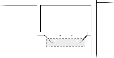
When you click the arrow at the end of the door swing arc, the dynamics begin and markers appear below the opening (see Figure 7.15), indicating the preset sizes to which the door and swing can be changed. In this example, you can use the door for openings from 2′-0″ to 3′-6″, at 6″ intervals. (The tooltip shows where the cursor is, not the door size.)
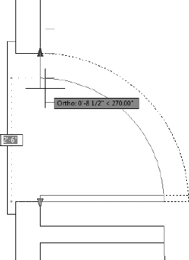
FIGURE 7.15 Markers appear at the increments where the door's swing can be adjusted.
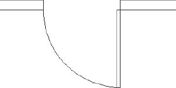
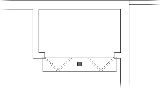
Once you set a new size, the door and swing take on that size, as shown in Figure 7.16, whereas the door thickness remains the same. Now you can move this door to a smaller opening.
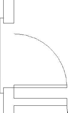
FIGURE 7.16 The dynamic door block with a smaller door and swing
Later in this chapter, when I introduce palettes, I'll show you where to find sample dynamic blocks. For instructions on creating and using dynamic blocks, see Chapter 9.
Understanding and Using Groups
Another way you can make several objects act as one is to use the GROUP command. Groups differ from blocks in that they do not replace separate objects with a single definition but instead associate several objects by name so that they react as if they were a single object.
Selecting one member object from the group selects all the members. Unlike objects in a block, members of a group can be added or removed, and you can toggle the group to allow the individual members to be selected. Use groups when you know that the association between the objects is not permanent, and use blocks when it might be. The procedure for creating a group is as follows:
Some similar programs use the term named selection set to represent what AutoCAD calls a group.
 Make sure I07-03-InteriorDoor.dwg (M07-03-InteriorDoor.dwg) is open.
- Start the GROUP command by clicking the Group button on the Home tab Groups panel.
- Select the four rectangles that compose the closet door, as shown in Figure 7.17. Do not press yet.
FIGURE 7.17 Selecting the closet door
- With the closet door selected, enter N or select New at the command line to specify a name for your group.
- At the Enter a group name: prompt, name your group CLOSETDOOR. Press to define the group name.
The command line confirms the group creation: Group “CLOSETDOOR” has been created.
- Select any one of the four rectangles that define the closet door.
Although you selected only one door panel, all four door panels highlight, and a bounding box defining the extents of your CLOSETDOOR group displays along with a single grip at the group's centroid (see Figure 7.18).
FIGURE 7.18 The CLOSETDOOR group in a selected state with bounding box and centroid grip
 Click the Group Selection On/Off button on the Home tab Groups panel to turn off group selection temporarily.
- Select any one of the four door panels that define the closet door.
Because Group Selection is currently disabled, only the panel you selected is highlighted (see Figure 7.19). In this state, you could modify the polyline defining the door panel you selected as if it were an ungrouped entity.
FIGURE 7.19 Single object within the CLOSETDOOR group selected with Group Selection turned Off
Groups are oftentimes utilized as a temporary drafting tool. As such, to ensure that your AutoCAD drawings remain uncluttered and performing at their best, you'll want to dispose of unneeded groups when you're finished with them.
- Click the Group Selection On/Off button once again, this time to re-enable Group Selection. The Group Selection On/Off icon should display with a blue background.
 Select any one of the four door panels to select the CLOSETDOOR group.
- Click the Ungroup button on the Home tab Groups panel.
The CLOSETDOOR group is discarded, and the command line reads Group CLOSETDOOR exploded.
AutoCAD versions prior to the 2012 release included a limited subset of creation, editing, and management tools; AutoCAD has included a Groups feature for many releases. Despite these limitations, the Group object itself is the same as it was in earlier versions, making it possible to exchange drawings freely with groups between all recent AutoCAD versions.
Finding Blocks in a Drawing
You can detect blocks in a drawing in at least three ways: by using grips, by using the LIST command, and by looking at the Properties palette.
Using Grips to Detect a Block
Grips appear on objects that are selected when no command is started. When an object that isn't a block is selected, grips appear at strategic places, such as endpoints, midpoints, and center points. But if you select a block, by default only one grip appears, and it's always located at the block's insertion point. Because of this, clicking an object when no command is started is a quick way to see whether the object is a block:
- Make sure I07-03-InteriorDoor.dwg (M07-03-InteriorDoor.dwg) is open.
- Click one of the door swings.
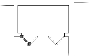
The door and swing turn into dashed lines, and a square blue grip appears at the hinge point, as shown in Figure 7.20.
- Press Esc to clear the grip.
FIGURE 7.20 Blocks have only one grip, which is at the insertion point.
- Expand the Application menu.
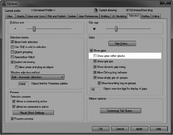
- Click the Options button at the bottom of the menu to open the Options dialog box, and then click the Selection tab.
The Grips group is on the right side, and Show Grips Within Blocks is unchecked by default (see Figure 7.21). If this option is checked and you click a block while no command is running, grips appear on all objects in the block, as if they weren't blocked. Leave this setting unchecked.
FIGURE 7.21 The Show Grips Within Blocks option
You can also change the size of the grip and any of the three color states. By default, unselected grips are blue, grips that you click to select are red, and grips over which you pause the cursor are green.
- Click OK or Cancel to close the Options dialog box.
You'll look at grips in more detail in Chapter 12, “Dimensioning a Drawing.” You might need to know more about a block than just whether something is one. If that is the case, you'll need to use the LIST command.
Using the List Command to Detect a Block
Much like the Properties palette, the LIST command can be used to gather information about a selected object. Although both are effective tools for reporting information about objects in a drawing, the LIST command displays only information. Unlike in the Properties palette, you cannot make changes to properties such as the layer. Despite this limitation, many users like the lightweight and concise nature of the LIST command and prefer it to the Properties palette. The following exercise demonstrates how to use the LIST command to learn more about a block:
- Continue using I07-03-InteriorDoor.dwg (M07-03-InteriorDoor.dwg), or open it if it's not already open.
 Click the List button from the Home tab expanded Properties panel, or enter LI at the Type a Command: prompt.
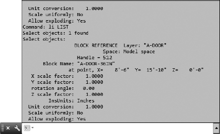
- Click the back door block and then press .
The AutoCAD command line temporarily expands to cover the drawing area (see Figure 7.22). In the command-line interface, you can see the words BLOCK REFERENCE Layer: “A-DOOR”, followed by 12 lines of text. These 13 lines describe the block you selected.
FIGURE 7.22 The expanded AutoCAD command line
The information displayed includes the following:
- Should the command line collapse, pressing F2 will expand the AutoCAD command line once again to display the information shown in Figure 7.22.
- Right-click, and choose Repeat LIST from the context menu.
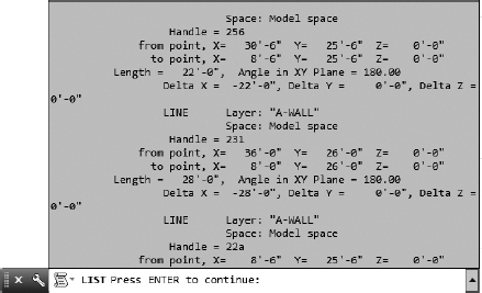
- At the Select objects: prompt, select each of the lines that make up the back staircase.
- Click one of the wall lines and then press .
 TIP The expanded AutoCAD command line isn't exclusively for use with the LIST command. Instead, it is a constantly scrolling history of the command prompt. The F2 key acts as a toggle to expand or consolidate the command line. You can even copy information from all but the bottom line for use inside or outside AutoCAD.
The command line expands again, and you can see information about the stair lines that you selected.
If the command line reads Press ENTER to continue: (see Figure 7.23), the amount of information is too large for the expanded command line.
FIGURE 7.23 The expanded command line indicating additional information from the LIST command
- Press to display the remaining information.
- As the remaining information reported by the LIST command displays, earlier information is pushed out of view. Although this information is no longer in view, you can use your mouse wheel, or the scrolling feature on some laptop track pads to view this earlier information.
Using the Properties Palette to Examine a Block
In Chapter 6, you used the Properties palette to change the individual linetype scale for the roof objects. It can also be a tool for investigating objects in your drawing. When the Properties palette is open and only one object is selected, the palette displays data specific to the selected object. If multiple objects are selected, it shows only the data shared by those objects.
Given the contextual nature of the Properties palette, it's important to note this behavior. As an example, information such as the name of a block will display only when one or more of that same block is selected. In contrast, selecting both a block and a line will display only the properties both objects share (such as layer), omitting differences (such as block name).
- Continue using I07-03-InteriorDoor.dwg (M07-03-InteriorDoor.dwg), or open it if it's not already open.
- Select one of the door blocks.
 Click the Properties button on the View tab Palettes panel of the Ribbon. Alternatively, you can right-click and choose Properties from the context menu, or press Ctrl+1.
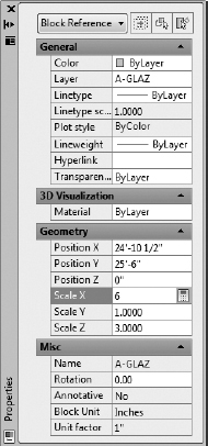
The Properties palette opens. The data displayed on the palette is similar to that displayed when you used the LIST command, but it's in a slightly different form (see Figure 7.24). At the top of the dialog box, a drop-down list displays the type of object selected—in this case, a block reference. The fields that are white signify items that you can change directly in the palette, and items that are grayed out cannot be changed. You can't change any values in the AutoCAD text window.
- Close the Properties palette by clicking the X in the upper-left or upper-right corner. Then press Esc to deselect the door block.
Block insertion means the same thing as block reference, and both are casually called blocks.
![]() TIP The X you click to close the Properties palette is in the upper-left or upper-right corner of the palette if it's floating and in the upper-right corner if it's docked.
TIP The X you click to close the Properties palette is in the upper-left or upper-right corner of the palette if it's floating and in the upper-right corner if it's docked.
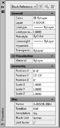
FIGURE 7.24 The Properties palette with a door block selected
If you're ever working on a drawing that someone else created, these tools for finding out about objects will be invaluable. The next exercise on working with blocks involves placing windows in the walls of the cabin.
Creating a Window Block
You can create all the windows in the cabin floor plan from one block, even though the windows are four different sizes (see Figure 7.25). You'll create a window block and then go from room to room to insert the block into the walls:
- Continue using I07-03-InteriorDoor.dwg (M07-03-InteriorDoor.dwg), or open it if it's not already open.
- Make layer 0 the current layer.
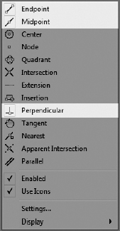
- Right-click the Object Snap button on the status bar, and click the Midpoint and Perpendicular osnaps, if necessary, to set them as running osnaps, and then deselect Intersection.
The Osnap menu should look similar to Figure 7.26. Turn on the Object Snap option in the status bar.
FIGURE 7.25 The cabin windows in the floor plan
FIGURE 7.26 The Osnap menu
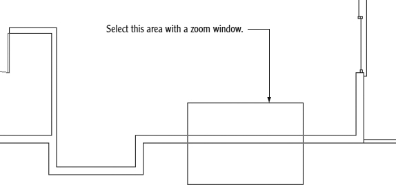
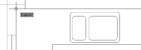
- Using a zoom window, zoom in to a horizontal section of wall where there are no jamb lines or intersections with other walls (see Figure 7.27).
Because the widths of the windows in the cabin are multiples of 12″ (305 mm), you can insert a block made from a 12″ (305 mm) wide window for each window, and you can apply an X scale factor to the block to make it the right width. The first step is to draw a 12 ″ (305 mm) wide window inside the wall lines.
FIGURE 7.27 Making a zoom window
 Start the LINE command, and then click the Nearest Osnap button on the Shift+right-click menu or enter NEA.
The Nearest osnap will allow you to start a line on one of the wall lines. It snaps the cursor to any part of any object that is under the cursor and guarantees that the objects form an intersection but do not cross.
Use the Nearest Osnap button when you want to locate a point somewhere on an object but aren't concerned exactly where on the object the point is located.
- Move the cursor to the upper wall line, a little to the left of the center of the screen and, with the hourglass-shaped marker displayed as shown in Figure 7.28, click.
FIGURE 7.28 Starting the line by using the Nearest osnap
A line begins on the upper wall line.
- Move the cursor to the lower wall line. The Perpendicular marker appears directly below the point you previously picked. When it's displayed, click.
The line is drawn between the wall lines, as shown in Figure 7.29. Press
to end the LINE command.FIGURE 7.29 Drawing the first window line
- Start the OFFSET command, and set the offset distance to 12(305).
- Pick the line you just drew, and then pick a point to the right of that line.
The line is offset 12″ (305 mm) to the right. Press
to end the OFFSET command. - Start the LINE command again to draw a line between the midpoint of the line you first drew and the midpoint, or, perpendicular to the line that was just offset.
After pressing
to end the LINE command, your drawing should look like Figure 7.30.FIGURE 7.30 Completed lines for the window block
- Save your drawing as I07-04-WindowBlock.dwg (M07-04-WindowBlock.dwg) by choosing Application menu Save As Drawing.


The three lines you've drawn will make up a window block. They represent the two jamb lines and the glass (usually called glazing). By varying the X scale factor from 2 to 6, you can create windows 2′ (610 mm), 3′ (915 mm), 4′ (1220 mm), 5′ (1525 mm), and 6′ (1830 mm) wide. This is a single-line representation, with no double lines to indicate the frames, so for scaling the blocks, there is no thickness issue as there was with the doors.
Before you create the block, you need to decide the best place for the insertion point. For the doors, you chose the hinge point because you always know where it will be in the drawing. Locating a similar strategic point for the window is a little more difficult but certainly possible.
You know the insertion point shouldn't be on the horizontal line representing the glazing, because the insertion point will always rest in the middle of the wall. There is no guideline in the drawing for the middle of the wall, and doing so would require a temporary tracking point every time a window is inserted. Windows are usually dimensioned to the midpoint of the glazing line rather than to either jamb line, so you don't want the insertion point to be at the endpoint of a jamb line. The insertion point needs to be positioned on a wall line but also lined up with the midpoint of the glazing line.
To locate this point, you'll use an object snap called Mid Between 2 Points. As the name suggests, the M2P osnap, as it's commonly called, snaps to a point midway between two other points you select. Follow these steps to set the base point for the window block along the outside wall line and midway between the window's edges:
- Make sure I07-04-WindowBlock.dwg (M07-04-WindowBlock.dwg) is open.
- Start the BLOCK command by clicking the Create Block button on the Home tab Block panel.
- In the Block Definition dialog box, enter A-GLAZ for the block name, and then click the Pick Point button.
As mentioned earlier, in the architectural discipline, windows are often referred to as glazing. The U.S. National CAD Standard also uses the term, making the NCS code for windows GLAZ.
- Back in the drawing, activate the Mid Between 2 Points option found on the Shift+right-click context menu. Alternatively, you can enter M2P at the command line.
The Mid Between 2 Points object snap is rather unique in that it is generally used in conjunction with other osnaps and is not found on the Object Snap toolbar. In this case, you want to find the midpoint between two endpoints.
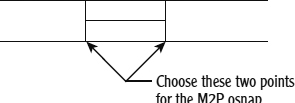
- With the Endpoint osnap running, move the cursor to the lower end of the left window jamb (see Figure 7.31) and click when the Endpoint marker appears.
FIGURE 7.31 Selecting the two endpoints for the M2P osnap
- Click the lower end of the right jamb to define the insertion point midway between the two endpoints that you picked.
- In the Block Definition dialog box, click the Select Objects button.
- Back in the drawing, select the two jamb lines and the glazing line, and then press .
- Back in the dialog box, make sure of the following:
- The Open In Block Editor check box at the bottom is unchecked.
- The Delete radio button is selected.
- Units are set to Inches (Millimeters).
- Click OK.
The A-GLAZ block has been defined, and the 12″ (305 mm) window has been erased.
- Use Zoom Previous to zoom out to a view of the whole floor plan.
- Save your drawing as I07-05-WindowDefinition.dwg (M07-05-WindowDefinition.dwg).
This completes the definition of the block that will represent the windows. The next task is to insert the A-GLAZ block where the windows will be located and scale them properly.
Inserting the Window Block
Several factors come into play when you're deciding where to locate windows in a floor plan:
- The structure of the building
- The appearance of windows from outside the building
- The appearance of windows from inside a room
- The location of fixtures that might interfere with placement
- The sun angle and climate considerations
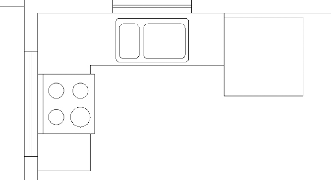
For this exercise, you'll work on the windows for each room, starting with the kitchen, and make a total of five windows at either 3′-0″, 4′-0″, 5′-0″, or 6′-0″ wide (see Figure 7.32).
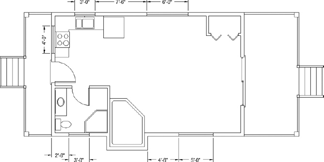
FIGURE 7.32 The cabin's window sizes and locations
Rotating a Block during Insertion
As you can see in Figure 7.32, the kitchen has windows on two walls: one 4′-0″ (1220 mm) window centered over the stove in the back wall and one 3′-0″ (915 mm) window centered over the sink in the top wall. You'll make the 4′ (1220 mm) window first:
- Make sure I07-05-WindowDefinition.dwg (M07-05-WindowDefinition.dwg) is open.
- Thaw the A-FLOR-FIXT layer. You'll need to see the sink and stove to place the windows properly.
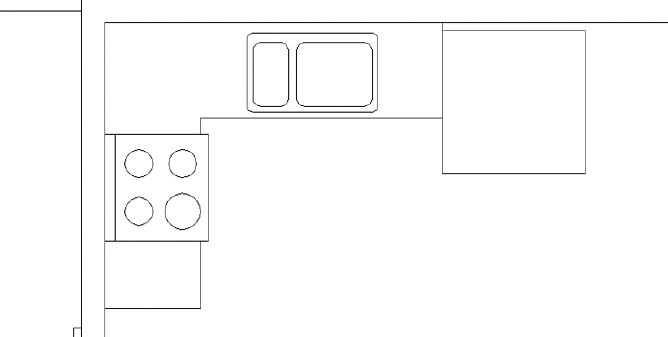
- Zoom in to a view of the kitchen so that you can see both walls, as shown in Figure 7.33.
- Click the Polar Tracking button on the status bar to turn on Polar Tracking.
Polar Tracking, Object Snap, Object Snap Tracking, and Dynamic Input should now be in their On positions.
- Create a new layer by clicking the Layer Properties button and then clicking the New Layer button in the Layer Properties Manager dialog box.
The new Layer1 layer appears and is highlighted. Enter A-GLAZ
to rename the layer.FIGURE 7.33 Zooming in to the kitchen
- Click the Color swatch in the A-GLAZ row to open the Select Color dialog box, with the white swatch highlighted and white listed in the Color text box.
- Enter 31 to change the color to a bright orange. The Select Color dialog box closes.
- With A-GLAZ still highlighted in the Layer Properties Manager dialog box, click the Set Current button, or double-click the name of the layer, to make the A-GLAZ layer current.
- Close or autohide the Layer Properties Manager.
- Start the INSERT command (click the Insert button in the Block panel).
- Open the Name drop-down list in the Insert dialog box.
- In the list of blocks, click A-GLAZ. Be sure all three Specify On-Screen check boxes are selected, and then click OK.
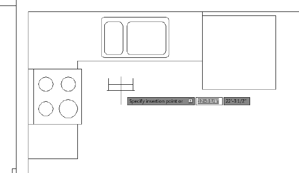
In your drawing, the 12″ (305 mm) window block is attached to the cursor at the insertion point (see Figure 7.34).
Note that it's still in the same horizontal orientation that it was in when you defined the block. To fit it into the left wall, you'll need to rotate it as you insert it.
- Move the cursor along the inside wall line near the midpoint of the stove.
FIGURE 7.34 The A-GLAZ block attached to the cursor
The stove line overlaps the wall line, and the midpoints of each are close together.
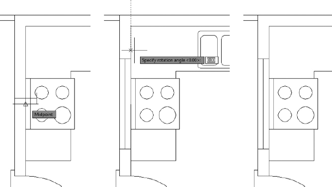
- Make sure the cursor is over the stove's midpoint (the lower of the two, as shown at the left of Figure 7.35), and then click.
FIGURE 7.35 Selecting the stove's midpoint as the insertion point (left), rotating the A-GLAZ block 90° (middle), and the final position (right)
- You're prompted for an X scale factor. This is a 4′-0″ (1220 mm) window, so enter 4.
- For the Y scale factor, enter 1.
The Y scale factor will be 1 for all the A-GLAZ blocks because all the walls that have windows are 6″ wide—the same width as the A-GLAZ block.
The window block is now 4′-0″ (1220 mm), and you are prompted for the rotation angle.
- From the Specify rotation angle prompt, move the cursor so that it's directly above the insertion point.
The Polar Tracking lines and tooltip appear (see the middle image of Figure 7.35). They show you how the window will be positioned if the rotation stays at 90°. The window fits nicely into the wall here.
- With the tracking line and tooltip visible, click.
The A-GLAZ block appears in the left wall. The INSERT block command ends (see the right side of Figure 7.35).
- Save this drawing as I07-06-BlockRotate.dwg (M07-06-BlockRotate.dwg).
Using Snap Tracking to Set the Insertion Point
The window over the sink is centered on the sink, but the sink line doesn't overlap the wall as the stove line did. You'll use the same snap tracking procedure that you used in Chapter 5, “Developing Drawing Strategies: Part 2,” to set the window block's insertion point without the need to draw extraneous geometry. Refer to Figure 7.32, shown earlier, as you follow the procedure here:
- Make sure I07-06-BlockRotate.dwg (M07-06-BlockRotate.dwg) is open.
- Use the Pan and Zoom tools to get a better view of the top wall of the cabin.
You want to create one 3′-0″ (915 mm) window, centered over the sink. Be sure the Endpoint and Midpoint osnaps are running, and turn off the Perpendicular osnap.
- Start the INSERT command.
- Ensure that A-GLAZ is in the Name drop-down list, and check that all Specify On-Screen check boxes are marked. Click OK.
- At the Specify insertion point: prompt, position the crosshair cursor over the intersection of the inside wall lines in the top-left corner of the cabin, as shown in Figure 7.36.
FIGURE 7.36 Setting the first tracking point to locate the window block
- When the temporary track point appears inside the Endpoint marker, move the cursor, without clicking, over the Midpoint marker for the topmost line of the sink.
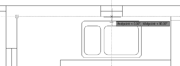
- When the temporary track point appears inside the Midpoint marker, move the cursor directly above that point to the intersection of the two track points. You have set, or acquired, two temporary tracking points without using the Temporary Tracking Point osnap.
TIP When Object Snap Tracking is turned on and the plus sign (+) appears at the Object Snap marker, a tracking point has been acquired. It remains acquired until you place the cursor directly on the object snap symbol a second time or until that part of the command is done.
When the crosshair reaches a point directly above the first tracking point, a vertical tracking line appears, and the tooltip identifies the intersection of the two tracking lines as Endpoint: <0.00°, Midpoint: <90.00° (see Figure 7.37).
FIGURE 7.37 Setting the insertion point for the window block
- When you see this tooltip, click. This places the insertion point on the inside wall line, centered over the sink.
- At the X scale factor prompt, enter 3.
- Then, at the Y scale factor prompt, enter 1. Press again to accept the default rotation angle of 0.
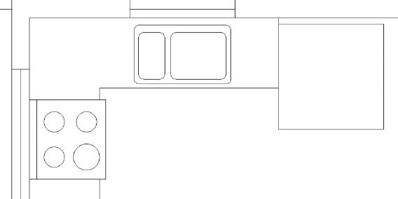
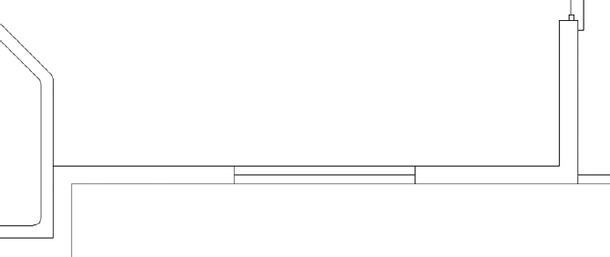
The 3′-0″ (915 mm) window is inserted into the wall behind the sink. Your kitchen, with the second window block inserted, should look like Figure 7.38.
FIGURE 7.38 The kitchen after inserting the second window block
- Save this drawing as I07-07-OsnapTracking.dwg (M07-07-OsnapTracking.dwg).
As you can see, by using the Object Snap Tracking tool, you can quickly and precisely locate an insertion point even when a snappable feature doesn't exist.
![]() TIP When using Object Snap Tracking, you'll inevitably acquire a tracking point that you don't need or want. To remove it, place the crosshair cursor on it momentarily. The tracking point will disappear.
TIP When using Object Snap Tracking, you'll inevitably acquire a tracking point that you don't need or want. To remove it, place the crosshair cursor on it momentarily. The tracking point will disappear.
Changing a Block's Scale Factor by Using Object Properties
You've inserted two different-sized window blocks at two different rotations. Just three remain to be inserted: one in the bathroom and two in the living room. You'll copy the horizontal kitchen window into the living room and then use the Properties palette to change the block's scale, resulting in a 6′-0″ (1830 mm) window.
- Make sure I07-07-OsnapTracking.dwg (M07-07-OsnapTracking.dwg) is open.
- Pan and zoom to get a good view of the kitchen and the top of the living room.
Referring back to Figure 7.32, you see that the windows are 7′-6″ (2286 mm) apart. Because the insertion points are centered horizontally in the blocks, the insertion points of the two windows are 12′-0″ (3659 mm) apart. You need to copy the 3′-0″ (915 mm) kitchen window 12′-0″ (3659 mm) to the right.

- Select the 3′-0″ (915 mm) kitchen window, and click the Copy tool from the Home tab Modify panel.
- At the Specify base point: prompt, click anywhere in the drawing area.
Clicking near the block that you are moving will keep everything visually compact.
- Move the cursor directly to the right.
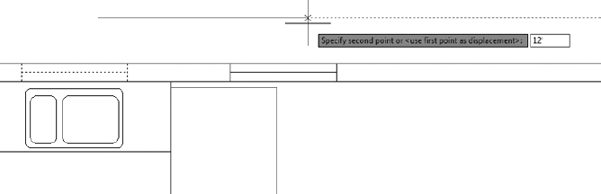
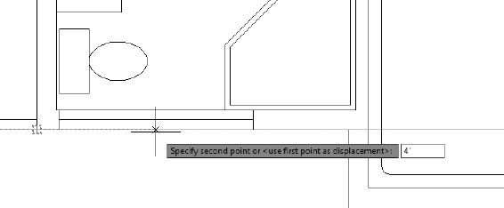
- At the Specify second point or <use first point as displacement>: prompt, enter 12′ (3659), as shown in Figure 7.39, and press again to terminate the COPY command.
FIGURE 7.39 Copying the kitchen window 12′ to the right
The window is copied 12′-0″ (3659 mm) to the right.
- Select the new window block, right-click, and then choose Properties from the context menu to open the Properties palette.
- In the Geometry rollout, locate the Scale X parameter and change its value to 6, as shown in Figure 7.40.
FIGURE 7.40 Change the block's X scale factor in the Properties palette.
- The window in the living room is now 6′-0″ (1830 mm) wide. Close the Properties palette, and press Esc to deselect the new window.
- Save this drawing as I07-08-ObjectProperties.dwg (M07-08-ObjectProperties.dwg).
As you've seen, you can change many parameters of an object, including the scale factors for a block definition, by using the Properties palette.
Finishing the Windows
The last two windows to insert are both in the bottom wall, one in the living room and one in the bathroom. You'll use skills you've already developed to place them:
- Make sure I07-08-ObjectProperties.dwg (M07-08-ObjectProperties.dwg) is open.
- Use the Zoom and Pan tools to adjust your view of the drawing down to the bottom wall between the front wall and the hot tub.
This window is 5′-0″ (1525 mm) wide, and its insertion point is 7′-0″ (2134 mm) from the pop-out for the hot tub (4′-6″ + 2′-6″, or 1372 mm + 762 mm).
- Place the cursor over the intersection of the outside wall lines on the upper-right side of the pop-out, as shown in Figure 7.41.
FIGURE 7.41 Selecting the first point to define the insertion point
- Start the INSERT command, verify that A-GLAZ appears in the Name field, and click OK.
- Move the cursor directly to the right, and enter 7' (2134).
The window is inserted 7′-0″ (2134 mm) to the right of the corner.
- Give the new block an X scale factor of 5, a Y scale factor of 1, and a rotation of 0″. The new window appears as shown in Figure 7.42.
The final window to draw is the 3′-0″ (915 mm) window in the bathroom. The insertion point is located 4′-0″ (1220 mm) from the bottom-left outside corner of the cabin. To create this window, you'll copy the living room window that you just drew and then change the X scale factor by using the Properties palette.
TIP If you can't recall a typed-in command, you can enter the first letter or two of the command, and the Autocomplete tool will suggest the rest of the command name for you. The tool will also give you a list of commands beginning with the same letter(s), which you may then cycle through using the Tab key. When the correct command appears at the command-line interface or dynamic input prompt, press to activate it.FIGURE 7.42 The new 5′-0″ (1525 mm) window in the living room
- Select the 5′-0″ (1525 mm) window in the living room, and start the COPY command.
- At the Specify base point: prompt, hold down the Shift key and press the right mouse button to open the Object Snap context menu.
 Click the Insert icon to activate the Insertion Point object snap and temporarily disable the running osnaps.
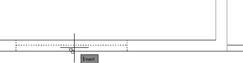
- Place the cursor over the window block until the Insert marker appears (see Figure 7.43). Then click to define the base point for the COPY command as the insertion point of the block.
FIGURE 7.43 Snapping to the insertion point of the block
- At the Specify second point or <use first point as displacement>: prompt, pause the cursor over the bottom-left outside corner of the cabin to acquire a temporary track point.
- Move the cursor directly to the right, and enter 4′ (1220), as shown in Figure 7.44.
FIGURE 7.44 Setting the COPY command's second point 4″ (1220 mm) from the corner
The window is copied to its new location 4′-0″ (1220 mm) from the corner.
- Press again to end the COPY command.
- Select the new window and open the Properties palette.
- Change the Scale X parameter to 3.
The window resizes to 3′-0″ (915 mm) wide, as shown in Figure 7.45.
FIGURE 7.45 The new 3′-0″ (915 mm) window in the bathroom
- Close the Properties palette, and press Esc to end the COPY command.
TIP In a cluttered area, you can enter NON at any Select Point: or Select Objects: prompt to disable all running osnaps for the duration of a single pick.
- Perform a Zoom Extents either by using the navigation bar or by double-clicking the middle button of your scroll wheel mouse.
This changes the view to include all the visible lines, and the view fills the drawing area.
- Use the scroll wheel to zoom out a little from the Extents view so that all objects are set in slightly from the edge of the drawing area.
Your drawing, with all the windows in place, should look like Figure 7.46.
FIGURE 7.46 The cabin drawing after inserting the windows and adjusting the zoom factor
- Save this drawing as I07-09-FinishingWindows.dwg (M07-09-FinishingWindows.dwg).

You have inserted five windows into the floor plan, each generated from the A-GLAZ block. You created the A-GLAZ block on layer 0 and then made the A-GLAZ layer current, so each window block reference took on the characteristics of the A-GLAZ layer when it was inserted.
![]() You can disassociate the components of blocks by using the EXPLODE command. The tool is found in the Home tab
You can disassociate the components of blocks by using the EXPLODE command. The tool is found in the Home tab ![]() Modify panel. Exploding a block has the effect of reducing the block to the objects that make it up. Exploding the A-GLAZ block reduces it to three lines, all on layer 0.
Modify panel. Exploding a block has the effect of reducing the block to the objects that make it up. Exploding the A-GLAZ block reduces it to three lines, all on layer 0.
You can also start the EXPLODE command by entering EXPLODE![]() .
.
![]() TIP All your windows are in walls 6″ (150 mm) thick, so the windows are all 6″ (150 mm) deep. But what if you want to put a window block in a 4″ (100 mm) wall between two interior rooms? You can still use the A-GLAZ block. During insertion, you change the Y scale factor to
TIP All your windows are in walls 6″ (150 mm) thick, so the windows are all 6″ (150 mm) deep. But what if you want to put a window block in a 4″ (100 mm) wall between two interior rooms? You can still use the A-GLAZ block. During insertion, you change the Y scale factor to ![]() to reflect the change in thickness of the wall.
to reflect the change in thickness of the wall.
![]()

Typically, when you choose to EXPLODE a block, you want the linework to retain the layer displayed in your drawing. Users of AutoCAD (not Autodesk® AutoCAD LT®) have another command named BURST that does just that. You can find the BURST command and the Explode Attributes button on the Express Tools tab ![]() Blocks panel. Like the EXPLODE command, BURST reduces the A-GLAZ block into three lines, but they will retain the correct A-GLAZ layer.
Blocks panel. Like the EXPLODE command, BURST reduces the A-GLAZ block into three lines, but they will retain the correct A-GLAZ layer.
Revising a Block
One of the biggest advantages to using blocks over manually drawing items such as doors and windows in your drawing is the ease with which blocks can be modified. Earlier, you used the Block Editor as you were defining blocks. In this section, you'll use the Block Editor again, this time not to define a new block but to modify an existing one. More specifically, you'll modify the A-GLAZ (window) block and see how the changes you make are reflected throughout your drawing.
Let's say that the client who's building the cabin finds out that double-glazing is required in all windows. You'll want the windows to show two lines for the glass. If you revise the A-GLAZ block definition, the changes you make in one block reference will be made in all six windows.
- Make sure I07-09-FinishingWindows.dwg (M07-09-FinishingWindows.dwg) is open.
NOTE Using standard commands, you can MOVE, ROTATE, COPY, ERASE, SCALE, and EXPLODE blocks. All objects in a block are associated and behave as if they were one object.
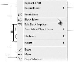
- Select the A-GLAZ block inserted over the stove, right-click to display the context menu, and select Block Editor, as shown in Figure 7.47.
FIGURE 7.47 Accessing the Block Editor from the context menu
Alternatively, you can access the Block Editor from the Insert tab
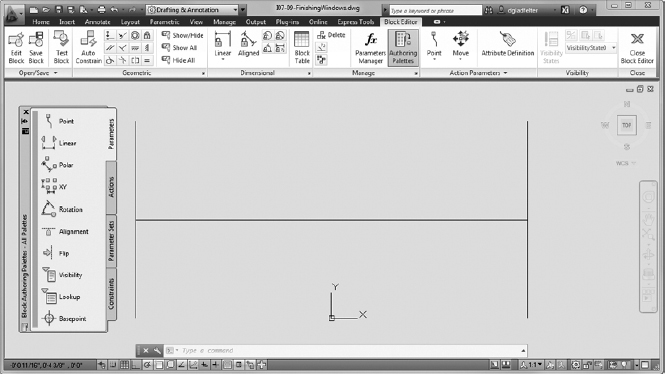
Block Definition panel Block Editor tool, or by entering BEDIT at the command line.In the drawing area, the rest of the drawing disappears, the background turns gray, and the Block Editor tab and panels appear in the Ribbon. Only the A-GLAZ block and the Block Authoring Palettes remain (see Figure 7.48). You are now in Block Editor mode.
FIGURE 7.48 The drawing area and Ribbon in Block Editor mode
- Use the OFFSET command to offset the glazing line 0.5″ (13 mm) up and down. Then erase the original horizontal line (see Figure 7.49).
FIGURE 7.49 The result of the modifications to the A-GLAZ block
This window block now has double-glazing.

 On the Open/Save panel, click the Save Block button.
- In the Close panel, at the far-right end of the Ribbon, click the Close Block Editor button.
If you click the Close Block Editor button without saving the changes to the block, an AutoCAD warning window appears, allowing you to save the changes or exit the Block Editor without saving the changes.
The Block Editor closes, and you are returned to the cabin drawing.
- Use the Zoom Previous tool to view the entire drawing. All windows in the cabin now have double-glazing.
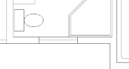
- Zoom in to a closer look at the kitchen in order to view some of the modified window block references (see Figure 7.50).
FIGURE 7.50 Zooming in to see the revised window blocks with double-glazing
- Use Zoom Previous to see a view of the entire floor plan.
- Save this drawing as I07A-FPLAYO.dwg (M07A-FPLAYO.dwg).

Sharing Information between Drawings
You can transfer most of the information in a drawing to another drawing. You can do so in several ways, depending on the kind of information that you need to transfer. You can drag blocks and lines from one open drawing to another when both drawings are visible within the Application window. You can copy layers, blocks, and other named objects from a closed drawing into an open one by using the DesignCenter. I'll demonstrate these two features—and touch on a few others—as I finish this chapter. Note that these features don't contribute to our cabin project, so the drawing changes you make in the following sections are only temporary and won't be saved.
Named objects are, quite simply, AutoCAD objects with names, such as blocks and layers. Lines, circles, and arcs don't have individual names, so they aren't named objects.
Dragging and Dropping between Two Open Drawings
In AutoCAD 2013, several drawings can be open at the same time, just like documents in a word processing program. You can control which one is visible, or you can tile two or more to be visible simultaneously. When more than one drawing is visible, you can drag objects from one drawing to another.
 With I07A-FPLAYO.dwg (M07A-FPLAYO.dwg) as the current drawing, click the New button on the Quick Access toolbar.
When you open the Application menu and then click the Open Drawings button, a list of the open drawings is displayed. To bring the file you want in front of the others, click it.
- In the Select Template dialog box, click the arrow next to the Open button and then click the Open With No Template—Imperial (Metric) option. These actions open a blank drawing.
 Click the Tile Vertically button from the View tab User Interface panel.
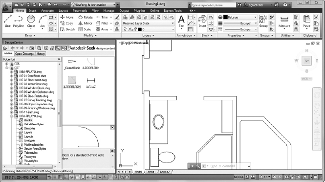
The new blank drawing (called Drawing#.dwg) appears alongside I07A-FPLAYO.dwg (M07A-FPLAYO.dwg), as shown in Figure 7.51.
FIGURE 7.51 The user interface with two drawings tiled
Each drawing has a title bar, but only one drawing can be active at a time. At this time, the blank drawing (probably named Drawing1) should be active. If it is, its title bar is dark blue or some other color, and the I07A-FPLAYO.dwg (M07A-FPLAYO.dwg) title bar is grayed out. If your I07A-FPLAYO.dwg (M07A-FPLAYO.dwg) drawing is active instead, click once in the blank drawing.
The new drawing might be called Drawing2.dwg or Drawing3.dwg. This doesn't affect how the exercise works.
- Open the Application menu, and then click Drawing Utilities Units. The Drawing Units dialog box opens.
- Change the type of units in the Length group to Architectural (or Decimal if you are working in metric), and then click OK.
- Click the I07A-FPLAYO.dwg (M07A-FPLAYO.dwg) drawing to make it active.
- Perform a Zoom Extents, and then use the scroll wheel to zoom out a little.
- Use the Layer drop-down list to make the A-WALL layer current, and then turn off the A-DECK-STRS, A-DOOR, A-FLOR-FIXT, and A-GLAZ layers.
The walls (A-WALL) and decks (A-DECK) should be the only lines visible.
- Use a selection window to select the cabin with its decks. Grips appear on all lines.
- Place the cursor on one of the wall lines at a point where there are no grips, and then click and hold down the left mouse button and move the mouse.
A copy of the selected cabin lines is attached to the mouse as if you had used the MOVE command (see Figure 7.52).
- Drag the cursor across the drawing to the center of the blank drawing, and then release the mouse button.
The blank drawing is now active and contains the lines for the walls and decks (see Figure 7.53).
- Zoom out so that you can see the entire drawing.
- Open the Layer drop-down list, and note that the new drawing (Drawing#.dwg in the example) now has the A-DECK and A-WALL layers.
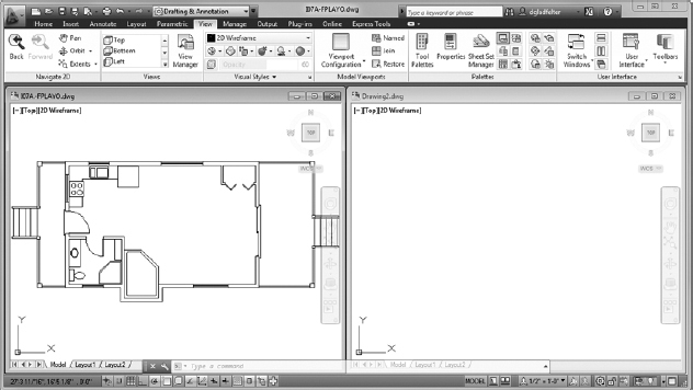
FIGURE 7.52 Dragging a selection of objects
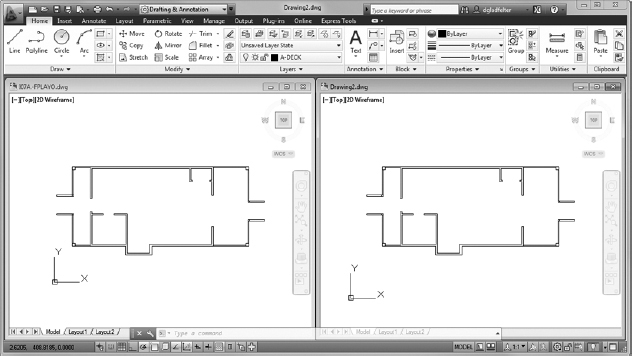
FIGURE 7.53 The result after dragging lines from one drawing to another
In this fashion, you can drag any visible objects from one drawing into another, including blocks. If you drag and drop a block, its definition is copied to the new drawing, along with all layers used by objects in the block. A shortcoming of this method is that you're simply inserting the objects into the other at an arbitrary coordinate. Because most plan sets are assembled so that the lower-left corner is at a certain coordinate (4′8′ in our case), the usefulness of this procedure is limited.
There is a way around this limitation. If you drag with the right mouse button instead of the left, a context menu will appear, providing a few options for placing the objects in the receiving drawing. Among the options available from the context menu is Paste To Orig Coords. This option will still insert the selected objects into the new drawing, but instead of inserting them at an arbitrary point, it will insert them in the same place they were located in the original drawing.
Copying Objects between Drawings
If you don't choose to have both open drawings visible in the Application window at the same time, you can always use the Copy and Paste tools available in most Windows-based programs. Here's the general procedure:
 Click the Maximize icon in the upper-right corner of the new drawing. The new drawing fills the screen.
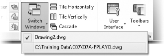
- Click the Switch Windows button from the View tab User Interface panel.
When the menu opens, notice at the bottom that the open drawings are displayed and the active one is checked (see Figure 7.54).
FIGURE 7.54 The Open Drawing menu with Drawing2.dwg active
- Click the I07A-FPLAYO.dwg (M07A-FPLAYO.dwg) drawing. It replaces the new drawing as the active drawing, and it fills the screen.
- Turn on the layers you turned off previously. Leave the A-WALL-HEAD and A-ROOF layers frozen.
TIP Because the A-WALL-HEAD and A-ROOF layers are frozen, and the other layers that aren't visible at the moment are turned off, you can use the LAYON command. As its name implies, the LAYON command turns on every layer in a drawing. You can find the LAYON command on the Home tab expanded Layers panel Turn All Layers On tool.
- Select the fixtures in the kitchen and bath from this drawing by using the selection tools you have learned, and then right-click and choose Clipboard Copy With Base Point from the context menu.
You're prompted to specify a base point in the I07A-FPLAYO.dwg (M07A-FPLAYO.dwg) drawing.
- Click the upper-left corner of the building by using the Endpoint osnap, and press Esc to deselect the objects.
- In the Window panel, click the Switch Windows button and then click Drawing#.dwg to make it active.
TIP You can also cycle through the open drawings by holding down the key and then pressing the Tab key.
- Right-click and choose Clipboard Paste from the context menu or press Ctrl+V.
- Pick the upper-left corner of the building by using the Endpoint osnap. The fixtures are accurately positioned in the new drawing.
If you check the layers, you'll see that the new drawing now has an A-FLOR-FIXT layer, in addition to the A-WALL and A-DECK layers.
Using the AutoCAD DesignCenter
The DesignCenter is a tool for copying named objects (blocks, layers, text styles, and so on) to an opened drawing from an unopened one. You can't copy lines, circles, and other unnamed objects unless they are part of a block. You'll see how this works by bringing some layers and a block into your new drawing from I07A-FPLAYO.dwg (M07A-FPLAYO.dwg):
- Make I07A-FPLAYO.dwg (M07A-FPLAYO.dwg) current, and then close it. Don't save changes.
 Maximize the window for your new drawing if it isn't already maximized.
- Open the DesignCenter from the Insert tab Content panel Design Center tool. Alternatively, you can open the DesignCenter by pressing Ctrl+2 or entering DC at the command line.
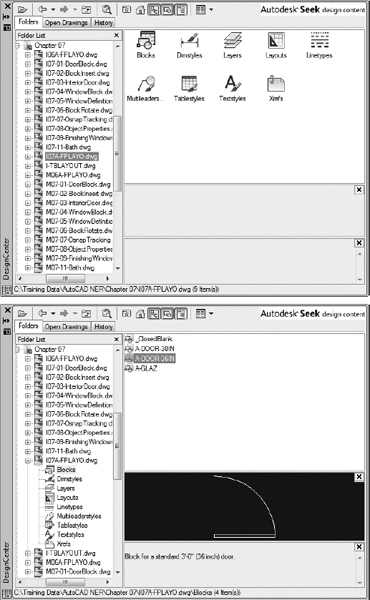
The DesignCenter palette appears on the drawing area. It can be docked, floating or, if floating, hidden (see Figure 7.55). Your screen might not look exactly like the samples shown here. The tree diagram of file folders on the left might or might not be visible. Also, your DesignCenter might be wider or narrower.
FIGURE 7.55 The DesignCenter docked (top), floating (middle), and hidden (bottom)
 Click the Tree View toggle button at the top of the DesignCenter (the fourth button from the right) a few times to close and open the file folder tree diagram.
You can resize the DesignCenter horizontally (and vertically as well, if it's floating), and you can resize the subpanels inside. If Auto-Hide is on, the DesignCenter hides behind the title bar until you put your cursor on it. Leave the tree view open.
 Click the Load button in the upper-left corner of the DesignCenter palette to open the Load dialog box. Navigate to your Training Data folder and open it.
- Highlight I07A-FPLAYO.dwg (M07A-FPLAYO.dwg), and click Open. The Load dialog box closes, and you are returned to your drawing.
Now the left side of the DesignCenter lists your drawings in the Training Data folder, and I07A-FPLAYO.dwg (M07A-FPLAYO.dwg) is highlighted; the right side of the DesignCenter shows the types of objects in I07A-FPLAYO.dwg that are available to be copied into the current drawing—in this case, Drawing3.dwg (see the top of Figure 7.56).
- On the left side once again, click the plus symbol (+) to the left of I07A-FPLAYO.dwg (M07A-FPLAYO.dwg).
The list of named objects in the right panel now appears below I07A-FPLAYO.dwg (M07A-FPLAYO.dwg) in the tree view on the left.
- Click the Layers icon on the left side. The list of layers in I07A-FPLAYO.dwg (M07A-FPLAYO.dwg) appears in the panel on the right (see the bottom of Figure 7.56).
 Click the Views button above the right window of the DesignCenter (the button on the far right), and choose List in the menu that opens.
This changes the view of layers displayed from icons into a list.
- Use the Shift and Ctrl keys to help you select all the layers except 0, A-DECK, A-FLOR-FIXT, and A-WALL (see Figure 7.57).
- Right-click one of the highlighted layers in the right window, and choose Add Layer(s) from the context menu that opens.
- Open the Layer drop-down list on the Layers panel. It now displays all the layers of the I07A-FPLAYO.dwg (M07A-FPLAYO.dwg) drawing, including those you just transferred to the Drawing#.dwg drawing.
If you prefer dragging and dropping, click and hold the left mouse button, drag the cursor onto the drawing, and then release the mouse button.
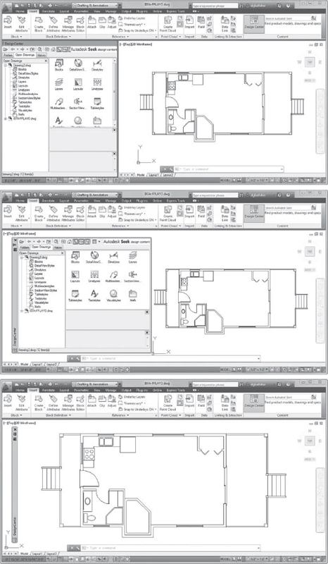
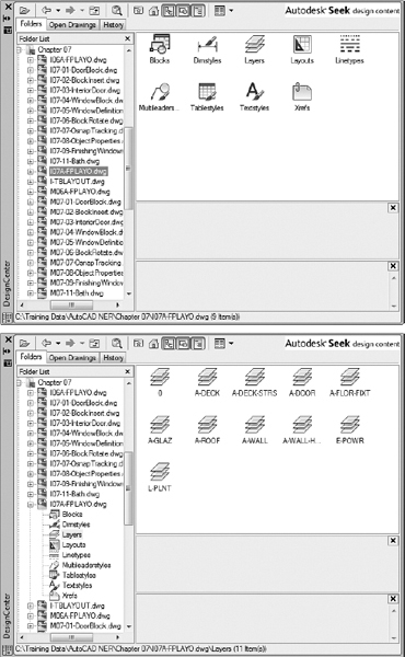
FIGURE 7.56 The DesignCenter displaying the files in the Training Data folder on the left and accessible objects on the right (top) and types of accessible objects on the left (bottom)
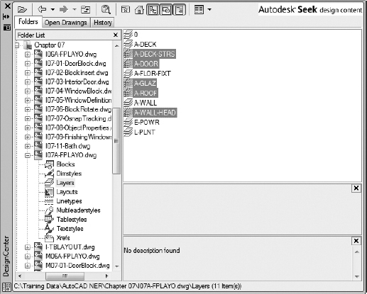
FIGURE 7.57 The DesignCenter with the layers to grab highlighted
Now let's see how this process works when you want to get a block from another drawing:
- On the left side of the DesignCenter, click Blocks in the list under the I07A-FPLAYO.dwg(M07A-FPLAYO.dwg) drawing.
On the right side, the list of blocks in that drawing appears (see the top of Figure 7.58).
 Click A-DOOR-36IN (A-DOOR-O915) in the right panel, and then, if necessary, click the Preview button at the top of the DesignCenter.
A picture of the block appears in the lower-right corner of the DesignCenter (see the bottom of Figure 7.58). You can resize the preview pane vertically.
- Open the Layer list, and make A-DOOR the current layer.
- Dock the DesignCenter on the left side of the drawing area if it's not already there, and then zoom in to the back door area of the drawing (see Figure 7.59). The Endpoint osnap should be running.
FIGURE 7.58 The DesignCenter with Blocks selected (top) and with the A-DOOR-36IN (A-DOOR-0915) block selected and Preview turned on (bottom)
FIGURE 7.59 Zoomed in to the back door area with the DesignCenter docked
- In the DesignCenter, click and drag A-DOOR-36IN from the list to the drawing and continue to hold the left mouse button down after the block appears at the cursor.
As the cursor comes onto the drawing, the A-DOOR-36IN block appears. Use the Endpoint osnap to locate the block at the opening, as you did earlier in this chapter (see Figure 7.60).
FIGURE 7.60 Dragging the A-DOOR-36IN block into Drawing# from the DesignCenter
- Click the Close icon in the upper-right corner of the DesignCenter to close it.
You can also right-click and drag a block from the DesignCenter into the current drawing. If you do this, a context menu appears; click Insert Block. This opens the Insert dialog box, and you can complete the insertion procedure.
- Keep your new drawing open in case you want to use it in the first few practice exercises at the end of this chapter. Otherwise, close it without saving it.
By doing this insertion, you've made the A-DOOR-36IN (A-DOOR-0915) block a part of your new drawing, and you can reinsert it in that drawing without the DesignCenter.
At the top of the DesignCenter window, the buttons on the left are tools for navigating through drives and folders to find the files you need to access; the buttons on the right give you options for viewing the named objects in the window.
Using Other Ways to Share Information between Drawings
You can transfer information between drawings in several other ways. This section looks at three of them:
- Use the WBLOCK command to take a portion of a drawing and create a new drawing file from the selected objects.
- Insert any DWG drawing file into any other drawing file.
- Create palettes of blocks that can be accessed for any drawing.
Using the Wblock Command
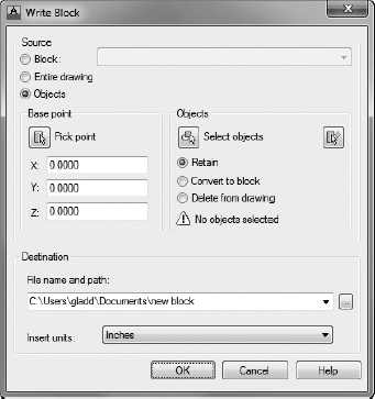
To perform a Write Block, or WBLOCK, operation, you create a new file by telling AutoCAD which elements of the current drawing you want in the new file. Let's say you want to create a new DWG file for the bathroom of the cabin. Here are the steps:
- Open I07A-FPLAYO.dwg (M07A-FPLAYO.dwg), and then pan and zoom to see the bathroom.
- Click the Create Block Write Block tool on the Insert tab Block Definition panel to start the WBLOCK command, as shown in Figure 7.61.
- At the top, under the Source group, click the Objects radio button (see Figure 7.62).
FIGURE 7.61 Starting the Write Block (WBLOCK) command from the Ribbon
FIGURE 7.62 The Write Block dialog box
In the middle portion, the Base Point and Objects groups are similar to those for creating a block.
As mentioned earlier, most project teams will establish a common location for their project. Assuming each of the drawings in your project are located in the same place, you can use 0,0,0 as the base point for the blocks you create with the WBLOCK command. You can accept the default Base Point of 0,0,0 to retain this common point in your cabin project.
- In the Objects group, click the Select Objects button.
- Use a window as well as individual picks to select everything you want to include, and press .
If you select with a crossing window here, you'll get more than you need, but you can clean up the new drawing later.
- Click the Retain radio button in this group, if necessary, so that the selected objects aren't deleted from the current drawing.
DESIGNCENTER OPTIONS
Here's a brief description of the functions of the DesignCenter buttons, from left to right:
Load Opens the Load dialog box, which you use to navigate to the drive, folder, or file from which you want to borrow named AutoCAD objects.
Back Moves you one step back in your navigation procedure.
Forward Moves you one step forward in your navigation procedure.
Up Moves up one level in the folder/file/named objects tree.
Search Opens a Search dialog box in which you can search for a file.
Favorites Displays a list of files and folders that you have previously set up.
Home Navigates to the DesignCenter folder in the AutoCAD program. This folder has subfolders of sample files that contain libraries of blocks and other named objects to import through the DesignCenter. You can designate a different Home folder by selecting the folder, right-clicking, and then choosing Set As Home from the context menu.
Tree View Toggle Opens or shuts the left panel that displays the logical tree of folders, files, and unnamed objects.
Preview Opens or shuts a preview window at the bottom of the right palette window. When you highlight a drawing or block in the palette window, a preview appears. You can resize the preview pane.
Description Displays or hides a previously written description of a block or drawing. You can resize the Description pane.
Views Controls how the items in the palette window are displayed. There are four choices: Large Icons, Small Icons, List, and Details.
- In the Destination area, enter a filename—say, I07-11-Bath.dwg (M07-11-Bath.dwg)—for the new drawing, and choose a folder in which to save it.
- In the Insert Units drop-down list, select Inches or Millimeters, in case the new drawing is used in a drawing that has units other than Architectural or Decimal.
- Click OK. A preview window briefly appears, the command ends, and the selected material is now a new drawing file located in the folder that you specified.
- Close the I07A-FPLAYO.dwg (M07A-FPLAYO.dwg) drawing without saving any changes.
You can use the WBLOCK command in three ways, which are available via radio buttons at the top of the Write Block dialog box in the Source group. Here's a brief description of each:
Block To make a drawing file out of a block that's defined in the current drawing, select the name of the block from the drop-down list at the top and then follow the procedure in steps 4 through 9 in the preceding exercise. When you follow this procedure, the objects in the new drawing are no longer a block. Wblocking a block has the effect of exploding it.
Entire Drawing Click this button to purge a drawing of unwanted objects such as layers that have no objects on them and block definitions that have no references in the drawing. You aren't prompted to select anything except the information called for in the preceding steps 4 through 9. You can keep the same drawing name or enter a new one. A preferable way to accomplish the same task is to use the PURGE command:
- Open the Application menu.
- Click Drawing Utilities Purge or enter PURGE to open the Purge dialog box.
- Select which features you want to purge.
Objects You select which objects to use to create a new file, as in the preceding steps 1 through 9.
Inserting One Drawing into Another
When you insert a drawing into another drawing, it comes in as a block. You use the same Insert tool that you use to insert blocks, but in a slightly different way. For example, in the previous section, you Wblocked a portion of I07A-FPLAYO.dwg (M07A-FPLAYO.dwg) and made a new file called I07-11-Bath.dwg. Now suppose you want to insert I07-11-Bath.dwg into a new drawing. Take the following steps:
- Start a new drawing, Drawing#.dwg, and set it as current.
- Start the INSERT command.
- In the Insert dialog box, click the Browse button and then navigate to the folder containing I07-11-Bath.dwg (M07-11-Bath.dwg).
- Open that folder, highlight I07-11-Bath.dwg, and then click Open to return to the Insert dialog box.
The drawing file that you selected is now displayed in the Name drop-down list. At this point, a copy of I07-11-Bath.dwg has been converted to a block definition in Drawing#.dwg.
- Set the insertion parameters and then click OK.
You can uncheck Specify On-Screen and accept the defaults for each parameter.
- Finish the insertion procedure as if you were inserting a block.
The contents of I07-11-Bath.dwg are displayed in your new drawing at the same location they were found in I07A-FPLAYO.dwg (M07A-FPLAYO.dwg).
You transfer blocks between drawings by dragging and dropping or by using the DesignCenter. You can also convert them into DWG files by using the WBLOCK command, and you can insert them back into other DWG files as blocks by using the INSERT command. These blocks become disassociated when they leave the drawing and can be inserted as a block when they enter another drawing.
Exploring AutoCAD Palettes
AutoCAD provides a tool called palettes to make blocks and other features or tools easily accessible for any drawing. You'll now take a brief look at the sample palettes that come with AutoCAD, and you'll see how to manage them on the screen:
- Open I07A-FPLAYO.dwg (M07A-FPLAYO.dwg) and zoom to the drawing's extents.
- Use the scroll wheel to zoom out a little.
 If palettes aren't already visible in the drawing area, click the Tool Palettes button, found on the View tab Palettes panel, to display the palettes (see Figure 7.63).
FIGURE 7.63 The tool palettes displayed on the screen
- Click the Architectural tab to display its content on the palette. Its tab might be abbreviated to read Archit, but pausing the cursor over the tab displays a tooltip showing the entire tab name.
Notice the scroll bar next to the title bar (see Figure 7.64). This appears when there is more content than the palette can show. Blocks that are shown with a lightning bolt symbol as part of the icon are dynamic blocks.
FIGURE 7.64 The tool palettes with the Architectural tab active
- Move the cursor to the title bar.
- Right-click, and choose Transparency from the context menu to open the Transparency dialog box (see Figure 7.65).
FIGURE 7.65 The Transparency dialog box
A FEW WORDS ABOUT TOOL PALETTES
You can also open the tool palettes from the menu bar by clicking Tools
Palettes Tool Palettes or by using the Ctrl+3 shortcut keys. Like the DesignCenter palette, tool palettes can be floating or docked on either side of the drawing area, and the navigation bar can be on the left or right side.Your palettes might appear different from those shown in a couple of ways. The ones shown here are positioned on the right side but aren't docked there. Yours might be transparent, showing your drawing beneath them, or your palettes might be hidden and show only the title bar. In Figure 7.63, several tabs are on the right side of the palette area, indicating the available palettes. On its left side is the palette title bar with control icons at the top and bottom.
On each palette is its content. The Hatches sample palette has hatch patterns and fills (discussed in Chapter 11, “Working with Hatches, Gradients, and Tool Palettes”), and the Draw and Modify palettes contain commands from the Draw and Modify toolbars, respectively.
Here you can toggle transparency on and off and adjust the degree of transparency for the tool palettes and many other palettes in the software.
 WARNING AutoCAD might display a notification dialog box, rather than the Transparency dialog box, if your video driver and operating system combination is unable to display palette transparency.
 - Configure the Transparency dialog box as follows:
- Ensure that the Disable All Window Transparency (Global) check box is not selected.
- In the General group, move the Opacity slider to its mid-position or a bit on the Solid side.
- Set the Rollover to 100% Opacity so that the palette is solid whenever the cursor is over it.
- Click OK.
Now the drawing is visible through the palettes (see Figure 7.66).
FIGURE 7.66 The palettes in Transparent mode
- Right-click the palettes' title bar, and choose Auto-Hide from the context menu.
- When the menu closes, move the cursor off the palettes.
The palettes disappear except for the title bar (see Figure 7.67). When you move the cursor back onto the title bar, the palettes reappear—a handy feature.
FIGURE 7.67 The palettes title bar with Auto-Hide on
- Close I07A-FPLAYO.dwg (M07A-FPLAYO.dwg) without saving any changes.
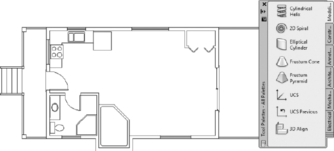
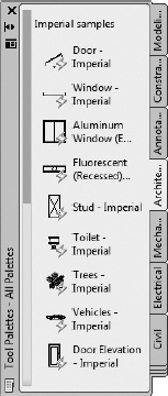
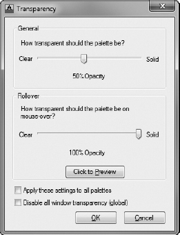
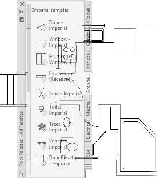
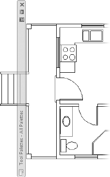
When they are in floating mode, the Properties palette and DesignCenter also have the Auto-Hide option.
With both Transparency and Auto-Hide active, the palettes are less intrusive and take up less screen area, but they remain easily accessible. In Chapter 11, you'll learn more about the Tool Palette feature, palette properties, and how to set up new palettes and change existing ones.
If You Would Like More Practice…
This chapter has outlined the procedures for setting up and using blocks, the WBLOCK command, and the AutoCAD DesignCenter. Blocks follow a set of complex rules, some of which are beyond the scope of this book.
Here are some suggestions that will give you some practice in working with blocks, drag-and-drop procedures, and the DesignCenter:
- Make blocks out of any of the fixtures in the bathroom or kitchen. Try to decide on the best location to use for the insertion point of each fixture. Then insert them back into the I07A-FPLAYO.dwg (M07A-FPLAYO.dwg) drawing in their original locations. Create them on layer 0, and then insert them on the A-FLOR-FIXT layer. Here's a list of the fixtures:
- Shower
- Bathroom sink and counter
- Toilet
- Stove
- Kitchen sink
- Refrigerator
- Hot tub
- At the end of Chapter 5, I suggested creating pieces of furniture for the kitchen, living room, and bedroom of the cabin. If you did that, it will be good practice to make blocks out of those pieces and insert them into the cabin floor plan. If you didn't do that exercise, you can do so now and then convert the pieces of furniture into blocks.
- Drag some of the dynamic blocks from the Civil, Structural, Electrical, Mechanical, Architectural, and Annotation sample palettes into the I07A-FPLAYO.dwg (M07A-FPLAYO.dwg) drawing, and experiment with them to see how they work. Figure 7.68 shows the cabin with a few trees and a car added from the Architectural palette.
- If you work in a profession or trade not directly concerned with architecture or construction, develop a few blocks that you can use in your own work:
- Electrical diagrams consist of many simple symbols, each of which can be a block.
- Cams and gears—or gear teeth—and other engine parts that have been made into blocks can be assembled into a mechanical drawing.
- Plumbing diagrams, like electrical ones, use a variety of symbols repetitively—valves, meters, pumps, and joints. You can easily make them into blocks and then reassemble them into the diagram.
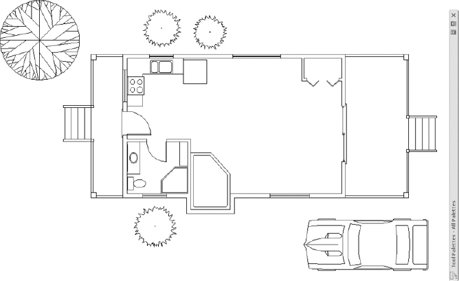
FIGURE 7.68 Trees and a car added from the Architectural palette
In each of these examples, choosing the most useful location for the insertion point will determine whether the block that you create will be a handy tool or a big frustration.
Are You Experienced?
Now you can…
- Create blocks out of existing objects in your drawing
- Insert blocks into your drawing
- Vary the size and rotation of blocks as they are inserted
- Detect blocks in a drawing
- Use point filters to locate an insertion point
- Revise a block
- Drag and drop objects from one drawing to another
- Use the AutoCAD DesignCenter
- Use the WBLOCK command
- Open palettes, and control their appearance