
CHAPTER 10
Generating Elevations
Now that you have created all the building components that will be in the floor plan, it's a good time to draw the exterior elevations. Elevations are horizontal views of a building, seen as if you were standing facing the building instead of looking down at it, as you do with a floor plan. An elevation view shows you how windows and doors fit into the walls and gives you an idea of how the building will look from the outside. In most architectural design projects, the drawings include at least four exterior elevations: front, back, and one for each side.
I'll go over how to create the south elevation first. Then I'll discuss some of the considerations necessary to complete the other elevations, and you'll have an opportunity to draw them on your own.
In mechanical drawing, the item being drawn is often a machine part or a fixture. The drafter uses orthographic projection—a method for illustrating an object in views set at right angles to each other: front, top, side, back, and so on—instead of elevations and plans. An exercise later in this chapter will give you practice with orthographic projection, but the procedure will be the same whether you're drawing buildings or mechanical objects.
In this chapter, you will learn to
- Draw an exterior elevation from a floor plan
- Use grips to copy objects
- Set up, name, and save user coordinate systems and views
- Transfer lines from one elevation to another
- Move and rotate elevations
Drawing the South Elevation
The first elevation view you'll create is the south view. This will reflect the appearance of the cabin as if you were looking at it from the side with the bath and living room windows. Before starting on these elevation views, however, you'll need to create some additional layers. These layers will mimic many of the layers already in your drawing but will use the major ELEV code to distinguish them from the layers used for your floor plan.
- Open I09A-FPLAYO.dwg (M09A-FPLAYO.dwg).
 Open the Layer Properties Manager palette from the Home tab
  Layers panel.
 Using the New Layer button, create the layers with the properties shown in the following table.
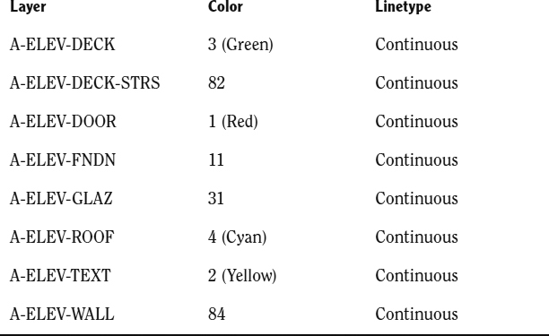
- Save this drawing as I10-01-ElevLayers.dwg (M10-01-ElevLayers.dwg).
Creating the South Elevation
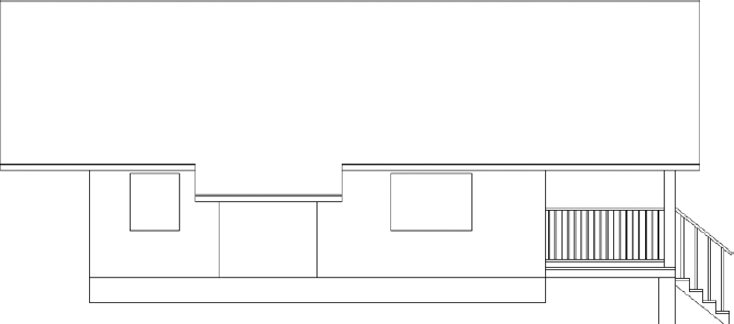
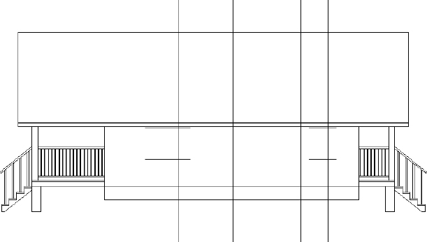
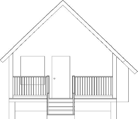
You draw the elevation by using techniques similar to those used on a traditional drafting board. You'll draw the south elevation view of the cabin directly below the floor plan by dropping lines down from key points on the floor plan and intersecting them with horizontal lines representing the heights of the corresponding components in the elevation. Figure 10.1 shows those heights. For this project, we'll consider the top of the screen to be north.
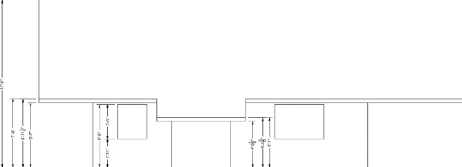
FIGURE 10.1 The south elevation with heights of components
Follow these steps:
- Continue using I10-01-ElevLayers.dwg (M10-01-ElevLayers.dwg), or open it if it's not already open.
- Freeze the A-ANNO-TABL, A-ANNO-TEXT, A-ANNO-TTLB, A-ANNO-TTLB-TEXT, and A-GRID layers. The A-AREA-NPLT layer should already be frozen, but check it and freeze it if it is still thawed. Thaw the A-ROOF layer.
- Offset the bottom horizontal wall line that is to the right of the pop-out 30′ (9144 mm) down. The offset line may be off the screen.
- Perform a Zoom Extents; then zoom out just enough to bring the offset wall line up off the bottom edge of the drawing area.
- Select the object and, when the grips are visible, click the left grip.
- Use the Perpendicular osnap to stretch the line to the left extent of the building, as shown in Figure 10.2.
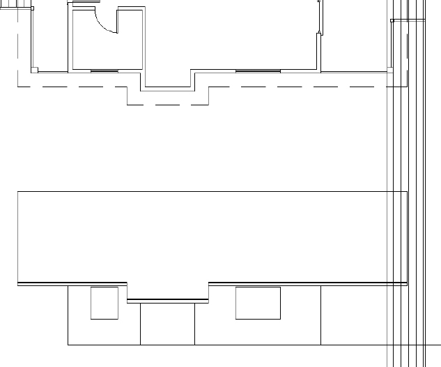
- Deselect the offset line. When done, your drawing should look like Figure 10.3.
- Save this drawing as I10-02-SouthElevPlacement.dwg (M10-02-SouthElevPlacement.dwg).
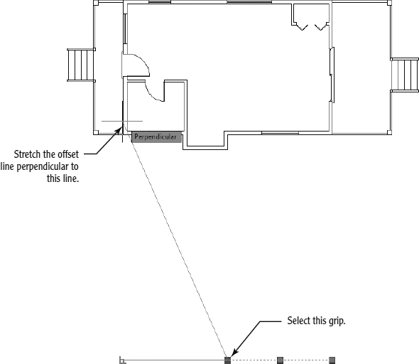
FIGURE 10.2 Using the grip to stretch the offset line
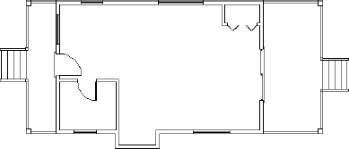
FIGURE 10.3 The floor plan with space below it for the south elevation
Setting Up Lines for the Heights
The line you offset establishes a baseline to represent the ground or the bottom of the cabin. You can now offset the other height lines from the baseline or from other height lines:
- Continue using I10-02-SouthElevPlacement.dwg (M10-02-SouthElevPlacement.dwg), or open it if it's not already open.
- Check the status bar to make sure that Polar Tracking, Object Snap, and Dynamic Input are in their On positions while the other buttons are Off. The Endpoint osnap should be running.
- Change the layer of the offset line from A-WALL to A-ELEV-WALL, and perform the following offsets:
- Offset the baseline 6′-7″ (2007 mm) up to mark the lowest edge of the roof supports and the bottom edge of the soffit.
A soffit is the under-side of the roof over-hang that extends from the outside edge of the roof back to the wall.
- Offset the same line 6′-11¼″ (2115 mm) and again 7′-0″ (2134 mm) to establish the lower and upper heights of the roof covering, respectively.
- Finally, offset the baseline up 17′-0″ (5182 mm) to mark the ridgeline of the roof.
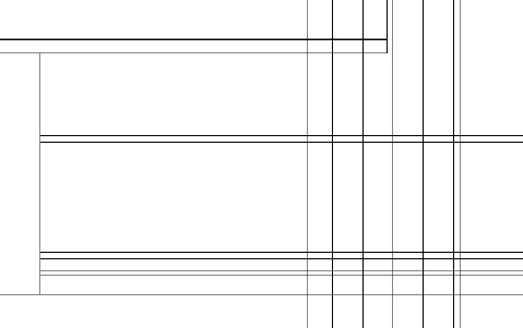
The lines should look like those shown in Figure 10.4.
FIGURE 10.4 Lines representing different heights in the elevation
- Offset the baseline 6′-7″ (2007 mm) up to mark the lowest edge of the roof supports and the bottom edge of the soffit.
- Offset the baseline 2′-11″ (889 mm) to represent the bottom of the windows.
- Offset the offset line 3′-6″ (1069 mm) to mark the top.
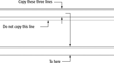
- To complete the lines representing different heights in the elevation, copy the three horizontal rooflines down 1′-11″ (584 mm).
These will be the lines at the edge of the roof, where it covers the pop-out (see Figure 10.5). Note that two of the lines appear to be at the same height. Use a crossing selection window to select the lines; be sure not to select the line representing the tops of the windows.
FIGURE 10.5 The horizontal height lines for the elevation in place
- Save this drawing as I10-03-SouthElevOffsets.dwg (M10-03-SouthElevOffsets.dwg).
Each of these lines represents the height of one or more components of the cabin. Now you'll drop lines down from the points in the floor plan that coincide with components that will be visible in the elevation. The south elevation will consist of the exterior walls, two windows, the pop-out, and the roof.
Using Construction Lines to Project Elevation Points
As you know, to create a standard line, you must define both a starting and ending point for the line. In addition to the standard LINE command, however, the Autodesk® AutoCAD® software offers two additional types of lines: rays and construction lines.
Rays Rays are a mix between standard and construction lines. Rays have a starting point but no end point.
Construction Lines Construction lines have neither a starting nor an ending point, and they extend to infinity in both directions.
Both rays and construction lines can be trimmed in much the same way as standard lines. Because, by definition, a construction line is a line of infinite length, trimming it will force it to extend to infinity in one direction. Consequently, using the TRIM command on a construction line will, at a minimum, turn it into a ray. Similarly, using the TRIM command on a ray will define an endpoint, consequently reducing it to a standard AutoCAD line.
You'll use construction lines to project key points from your floor plan to the area within the drawing where you will draw your south elevation. As you do this, pay attention to the way construction lines are reduced into rays, and rays into standard lines.
- Continue using I10-03-SouthElevOffsets.dwg (M10-03-SouthElevOffsets.dwg), or open it if it's not already open.
- Zoom in to the floor plan, and make sure Object Snap is turned on with the Endpoint osnap enabled.
 Start the XLINE (Construction Line) command from the expanded Draw panel on the Home tab.
- Enter V
 or select Ver at the Specify a point or [Hor/Ver/Ang/Bisect/Offset]: prompt to choose the Ver, or Vertical, option.
With the Vertical option, the XLINE command will create a vertical line extending to your south elevation and beyond at each point you select.
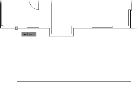
- Using the Endpoint osnap, choose the lower-left outside wall by the bathroom, as shown in Figure 10.6. Keep this drawing open as you continue to the next exercise.
Copying Objects by Using Grips
Construction lines, like most other objects in AutoCAD, have a number of grips. Selecting the construction line you just drew will make three grips (blue boxes) appear. Grips can be used to modify objects in your drawing quickly and easily.
Among the possible operations using grips is the Copy function. You'll create the remaining projection points using this method:
- Select the construction line you just drew.
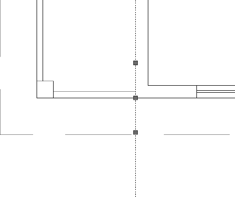
Three grips appear along the construction line: one at the insertion point and two more above and below it (see Figure 10.7).
FIGURE 10.6 Drawing a construction line to represent the outside wall by the bathroom
FIGURE 10.7 Select the construction line dropped from the floor plan.
- Click the middle grip on the construction line. (This is the same point you used to insert the construction line.)
The STRETCH command is a modifying tool that you use to lengthen or shorten lines and other objects. You'll have another chance to use it in Chapter 11, “Working with Hatches, Gradients, and Tool Palettes.”
The grip changes color from blue to red, and the prompt changes to Specify stretch point or [Base point/Copy/Undo/eXit]:. This is the STRETCH command. Any time you activate a grip, the STRETCH command automatically starts.
- Right-click, and choose Copy from the context menu.
This starts the COPY command, using the selected grip as the first point.
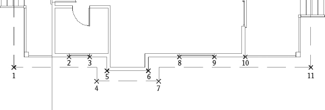
- With the Endpoint osnap running, select each of the 11 endpoints shown in Figure 10.8.
Every command that works with grips has a Copy option, which keeps the original object “as is” while you modify the copy. You can copy with grips in ways not possible with the COPY command.
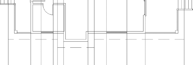
FIGURE 10.8 Copy the construction line to the 11 points shown here.
The construction line is copied to each of these corners and extends down to where you'll draw the south elevation.
- Press Esc twice to end the command, and deselect the line. Your drawing resembles Figure 10.9.
FIGURE 10.9 All the lines dropped down from the floor plan
- Save this drawing as I10-04-ProjectionLines.dwg (M10-04-ProjectionLines.dwg).
In the next section, you'll trim the lines as necessary to continue the elevation drawing.
GETTING A GRIP ON GRIPS
In Chapter 7, “Combining Objects into Blocks,” you saw how to use grips to detect whether an object is a block. Grips actually serve a larger function. The STRETCH command will automatically start when you select a single grip. With a single grip selected, the right-click menu offers a list of additional tools for editing objects quickly by using one or more of the following five commands: STRETCH, MOVE, ROTATE, SCALE, and MIRROR. These commands operate a little differently when using grips than when using them otherwise.
The commands can also perform a few more tasks with the help of grips. Each command has a Copy option. So, for example, if you rotate an object with grips, you can keep the original object unchanged while you make multiple copies of the object in various angles of rotation. You can't do this by using the ROTATE command in the regular way or by using the regular COPY command.
To use grips, follow these steps:
- When no commands have been started, click an object that you want to modify.
- Click the grip that will be the base point for the command's execution.
- Right-click at this point, and choose any of the five commands just described from the context menu that opens on the drawing area.
You can also cycle through these commands by pressing the spacebar and watching the command prompt.
- When you see the command you need, execute the necessary option.
- Enter X when you're finished.
- Press Esc to deselect the object.
The key to being able to use grips efficiently is in knowing which grip to select to start the process. This requires a good understanding of the five commands that work with grips.
This book doesn't cover grips in depth, but it introduces you to the basics. You'll get a chance to use the MOVE command with grips in this chapter, and you'll use grips again when you get to Chapter 12, “Dimensioning a Drawing.”
Keep the following in mind when working with grips:
- Each of the five commands available for use with grips requires a base point. For MIRROR, for example, the base point is the first point of the mirror line. By default, the base point is the grip that you select to activate the process. But you can change base points, as follows:
1. Select a grip, and enter B
.2. Pick a different point to serve as a base point.
3. Continue the command.
- When you use the Copy option with the MOVE command, you're essentially using the regular COPY command.
Trimming Lines in the Elevation
The next task is to extend and trim the appropriate lines in the elevation. You'll start by extending the rooflines:
- Continue using I10-04-ProjectionLines.dwg (M10-04-ProjectionLines.dwg), or open it if it's not already open.
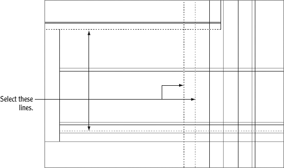
- Click the Extend button in the Modify panel of the Home tab, and then select the two outermost construction lines extending from the roofline in plan view and press . These are the boundary edges.

- Click once on each end of the top four horizontal lines: the ridgeline, the top and bottom of the roof covering, and the bottom of the soffit (see Figure 10.10).
- Start the TRIM command, and press when prompted to select cutting edges.

By not selecting any cutting edges, every edge in the drawing is used as a cutting edge.
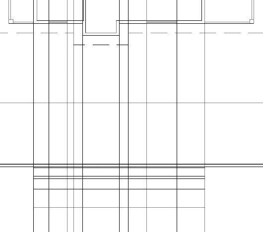
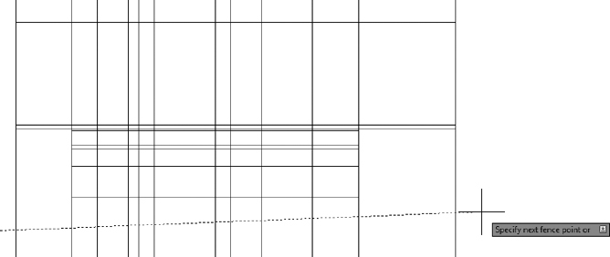
- Enter F to choose the Fence option.
- Draw a fence line along the bottom of your elevation, as shown in Figure 10.11.
FIGURE 10.10 The elevation after extending the rooflines
FIGURE 10.11 Trimming the lower construction line extensions by using the Fence option within the TRIM command
- Press to apply the fence line and end the TRIM command.
- Select one of the vertical lines extending down from the floor plan, and open the Properties palette (Ctrl+1).
The roof extends a little farther than the rest of the roof where the hot tub is located.
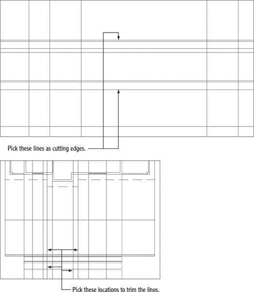
- Start the TRIM command, and select the two lines shown at the top of Figure 10.12.
FIGURE 10.12 The cutting edges for trimming the roof extension (top), and selecting the trim points (bottom)
 NOTE Notice that the extension lines are no longer construction lines. By using the TRIM command, you defined a start point for each construction line where it intersected a cutting edge. Because construction lines extend to infinity in both directions, our line is reduced to a ray. As you may recall, a ray has a start point but no endpoint.
 - After choosing the cutting edges, pick above and below the cutting edges, as shown at the bottom of Figure 10.12, to trim the construction lines.
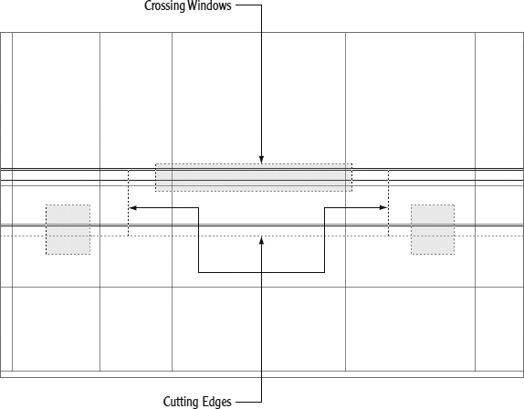
- Start the TRIM command again, and select the two roof extension lines you just created along with the bottom roofline as cutting edges (see Figure 10.13).
FIGURE 10.13 Defining the cutting edges and crossing windows to trim the roof extension
- Use a total of three crossing windows to complete the TRIM command, as shown in Figure 10.13.
 Start the FILLET command from the Home tab Modify panel.
- Using a 0 radius, pick the left side of the top roofline and the rear (left-side) vertical roof extension line.
- Repeat the FILLET command, this time selecting the right side of the top roofline and the front (left-side) vertical roof extension line.
This completes the roof outline in your elevation view. The only thing left to do is clean up the lines defining the two windows.
 From the extended Modify panel within the Home tab, choose the Break At Point tool.
- Select the lower window line at the Select object: prompt, and use the Midpoint osnap to specify the break point.
The line will appear unchanged visually; however, selecting it will reveal that the line has been divided into two separate line segments.
- Zoom in to the bathroom window, and start the FILLET command.
- Enter M to select the Multiple option at the Select first object prompt.
- Using a Fillet radius of 0, fillet each of the four corners of the bathroom window, as shown in Figure 10.14.
FIGURE 10.14 Using the FILLET command to complete the bathroom window
- Repeat steps 16 and 17 to complete the living room window toward the front of your cabin.
- Complete the elevation view by using the TRIM command to trim the two vertical lines representing the front and rear outside walls to the roof soffit line. When finished, the elevation should resemble Figure 10.15.
FIGURE 10.15 The completed elevation view
- Save the current drawing as I10-05-TrimElevation.dwg (M10-05-TrimElevation.dwg).
This is the basic process for generating an elevation: drop lines down from the floor plan, and trim the lines that need to be trimmed. The trick is to learn to see the picture you want somewhere among all the crossed lines and then to be able to use the TRIM command accurately to cut away the appropriate lines.
TIPS FOR USING THE TRIM AND EXTEND COMMANDS
TRIM and EXTEND are sister commands. Here are a few tips on how they work.
Basic Operation
Both commands involve two steps: selecting cutting edges (TRIM) or boundary edges (EXTEND) and then selecting the lines to be trimmed or extended:
- Select the cutting or boundary edges, and then press .
- Pick lines to trim or extend.
- Press to end the commands.
You can use the Fence option or a selection window to select several lines to trim or extend at one time.
Trimming and Extending in the Same Command
If you find that a cutting edge for trimming can also serve as a boundary edge for extending, hold down the Shift key and click a line to extend it to the cutting edge. The opposite is true for the EXTEND command.
Correcting Errors
It's easy to make a mistake in selecting cutting or boundary edges or in trimming and extending. You can correct a mistake in two ways:
- If you select the wrong cutting or boundary edge, do the following:
1. Enter R
, and then choose the lines again that were picked in error. They will lose their highlighting.2. If you need to keep selecting cutting or boundary edges, enter A
and select new lines.3. When finished, press
to move to the second part of the command. - If you trim or extend a line incorrectly, proceed as follows:
1. Enter U
, or right-click and choose Undo from the context menu. This undoes the last trim.2. Click Undo again if you need to untrim or unextend more lines.
3. When you have made all the corrections, continue trimming or extending.
4. Press
to end the command.
If the command ended and you click the Undo button, you will undo all trimming or extending that was done in the preceding command.
Assigning Elevation Layers
You set the A-ELEV-WALL layer as current as you began drawing your elevation view. At that point, you were mostly interested in getting the elevation's geometry in place, and not as interested in layers. With the geometry in place, now is a good time to pause for a moment and place everything on the correct layers. Currently, the exterior walls, roof, and windows are drawn. Follow these steps to assign A-ELEV-WALL, A-ELEV-ROOF, and A-ELEV-GLAZ, respectively, to those objects:
- Continue using I10-05-TrimElevation.dwg (M10-05-TrimElevation.dwg), or open it if it's not already open.
- Select the lines shown in Figure 10.16, and use the Layer pull-down found on the Layers panel of the Home tab to assign the A-ELEV-ROOF layer.
FIGURE 10.16 Assigning the A-ELEV-ROOF layer to the roof objects within the elevation view
- Repeat step 2, this time selecting the bathroom and living room windows and assigning the A-ELEV-GLAZ layer.
- Select the four vertical lines and the horizontal line running along the bottom of your elevation view and, using the process shown in step 2, assign the A-ELEV-WALL layer.
- Save the current drawing as I10-06-AssignLayers.dwg (M10-06-AssignLayers.dwg).
With each component of your elevation view on the proper layer, you can begin to refine the view further. Currently, the elevation view does not illustrate your deck, stairs, or foundation. Let's begin adding these components, starting with the front and rear decks.
Drawing the Decks in Elevation
The cabin sits on an 18″ (457 mm) foundation (which you'll add in the “Drawing the Supports and Foundation” section later in this chapter), with the surrounding land falling away from it at a slight angle. On the front and back sides are decks with stairways to step up to the door levels. In this section, you'll draw the front deck first, mirror it to the other end, and then adjust the second deck to match the conditions at the back of the cabin.
Drawing the Front Deck
Figure 10.17 shows the dimensions required to draw the horizontal elements of the stairway, while most vertical lines are dropped from the floor plan.
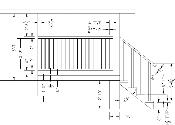
FIGURE 10.17 The front deck and stairs with dimensions
Follow these steps to draw the front deck:
- Continue using I10-06-AssignLayers.dwg (M10-06-AssignLayers.dwg), or open it if it's not already open.
- Make the A-ELEV-DECK layer current.
- Draw a horizontal line from the elevation's bottom-right corner of the wall directly to the right.
Make sure the line extends beyond the limits of the stairway in the floor plan.
- Start the XLINE (Construction Line) command.
- Choose the Vertical option, and draw lines from the corner post, the stairs, and the end of the railing in the floor plan, as shown in Figure 10.18.
FIGURE 10.18 Vertical construction lines drawn from deck post, stairs, and railings
- Zoom in to the right end of the cabin elevation.
Here you're first going to offset the horizontal line several times and then trim the resulting lines back to the lines that represent the post.
- Start the OFFSET command.
- Offset the horizontal line upward 6″ (152 mm), and press the Esc key to exit the command.
- Repeat steps 7 and 8 five times, offsetting the original line up by these distances:
 (194 mm)
 (295 mm)
 (1260 mm)
 (1312 mm)
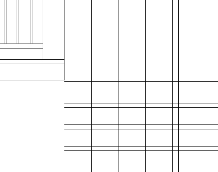
The right end of your elevation should look like Figure 10.19.
FIGURE 10.19 The offset lines for the stairs
- Start the TRIM command, and select the two post lines, the soffit line, and the third horizontal deck line (deck surface) from the bottom as the cutting edges (see Figure 10.20).
FIGURE 10.20 Select the cutting edges for the TRIM command.
- Continue using the TRIM command to clean up the construction lines you drew by doing the following:
- Trim all the deck horizontal lines to the right post line, and then trim the top four deck lines again, this time to the left post line.
- Trim the vertical post lines back to the soffit line on top and the third horizontal deck line below.
- Next, draw a short vertical line from the bottom of the right post line to the lowest horizontal line, as shown in Figure 10.21.
FIGURE 10.21 The deck and post lines after trimming them back to their proper lengths
- Save the current drawing as I10-07-FrontDeck.dwg (M10-07-FrontDeck.dwg).
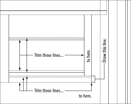
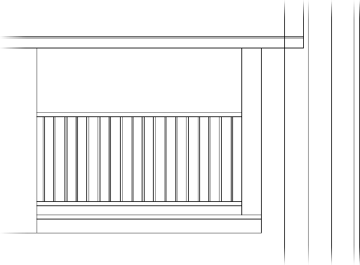
Drawing the Railing Posts with a Path Array
The railing posts are ![]() (20 mm) square components that are 3′-0″ (915 mm) long and spaced with a 4″ (102 mm) gap between each one. After the first object is drawn, you could apply strategies learned in earlier chapters to copy the remaining posts manually.
(20 mm) square components that are 3′-0″ (915 mm) long and spaced with a 4″ (102 mm) gap between each one. After the first object is drawn, you could apply strategies learned in earlier chapters to copy the remaining posts manually.
As you will see in a moment, the ARRAY command provides an efficient way to copy objects as an associative group. This associative group can be created in any one of three distinct ways: rectangular, polar, or what you'll use in this exercise—path. Using the Path Array (ARRAYPATH) command, each of the vertical railing posts will be created using only a single instance of one command. Here's how:
- Continue using I10-07-FrontDeck.dwg (M10-07-FrontDeck.dwg), or open it if it's not already open.
- Offset the left post line 4″ (102 mm) to the left, and then offset this line another
 (20 mm).
 - Trim these two lines back to the lower edge of the upper rail and to the upper edge of the lower rail (see Figure 10.22).
FIGURE 10.22 Draw the first railing post.
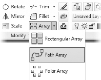
- On the Home tab Modify panel, expand the Array button and select Path Array, as shown in Figure 10.23.
FIGURE 10.23 Starting the Path Array (ARRAYPATH) command from the Ribbon
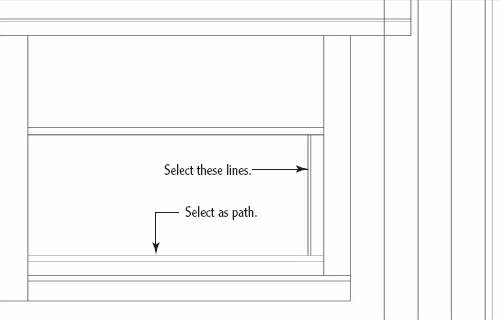
- At the Select objects: prompt, select the two lines composing the vertical railing post, as shown earlier in Figure 10.22. Press .
- Define the direction in which you would like to copy the vertical railing by selecting the lower horizontal railing line at the Select path curve: prompt (also shown earlier in Figure 10.22).
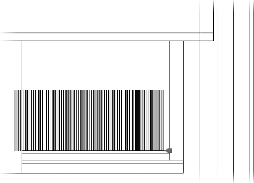
Because you have not yet defined any parameters for the array, the ARRAYPATH command fits a large number of vertical railings along the selected path, as shown in Figure 10.24.
FIGURE 10.24 Initial vertical railing placement created with the Path Array (ARRAYPATH) command
- Because the initial railing placement does not accurately reflect our intended placement, we'll make several modifications at the Select grip to edit array prompt:
- Select the Items options, or enter I at the command line.
- Enter
 (122 mm) at the Specify the distance between items along path or [Expression]: prompt.
 - Adjust the total number of vertical railings by entering 18 at the Specify number of items: prompt.
- Press to complete the ARRAYPATH command.
The array is created using the parameters specified in the preceding procedure, and it should now match Figure 10.25.
FIGURE 10.25 Final vertical railing placement created with the Path Array (ARRAYPATH) command
- Select the Items options, or enter I
- Save the current drawing as I10-07-RailingArray.dwg (M10-07-RailingArray.dwg).
Drawing the Stairs
There are four steps leading up to the cabin, each with an 8″ (204 mm) rise and a ![]() (41 mm) thick tread. The 10″ (254 mm) length of the steps, also called the run, is based on the lines dropped from the steps in the floor plan.
(41 mm) thick tread. The 10″ (254 mm) length of the steps, also called the run, is based on the lines dropped from the steps in the floor plan.
- Continue using I10-07-RailingArray.dwg(M10-07-RailingArray.dwg), or open it if it's not already open.
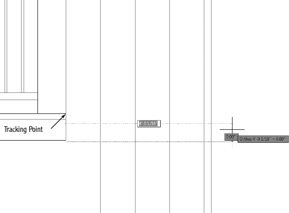
- Using Object Snap Tracking and direct input, draw a line from a point 8″ (204 mm) below the top of the deck directly to the right, well beyond the last vertical step line, as shown in Figure 10.26.
FIGURE 10.26 Drawing the first step tread
- Using the OFFSET command, make three copies of this line, each one 8″ (204 mm) below the previous.
These lines are the tops of the stair treads.
- Offset each of the stair tread lines downward
 (41 mm), as shown in Figure 10.27.
FIGURE 10.27 Offset the lines downward.
- Using the vertical step lines as cutting edges, trim each of the steps to its proper 10″ (254 mm) length.
Try using a crossing window to select multiple lines to trim at one time.
- Next, use the horizontal step lines as cutting edges to trim back the vertical lines, leaving the short, vertical line between each step intact.
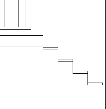
Your stairway should look like Figure 10.28.
FIGURE 10.28 The steps after trimming away the extraneous lines
For the stringer (the support for the steps), you need a line that matches the angle between each step.
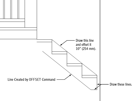
- Draw a line from the top-right corner of the first step to the top-right corner of the last step, and then offset this line 10 ″ (254 mm) so that the copy appears below the stairs, as shown in Figure 10.29.
- Draw a line from the bottom of the lowest step tread 8″ (204 mm) downward and then a few feet directly to the left.
- Fillet the bottom-left corner of the stringer with a radius of 0, as shown in Figure 10.29.
The last parts of the stairway to draw are the 2″ (51 mm) railing posts and the handrail.
- Move the angled line at the top of the stairs up 3′-6″ (1067 mm), and then offset it upward 2″ (51 mm).
FIGURE 10.29 Drawing the stringer
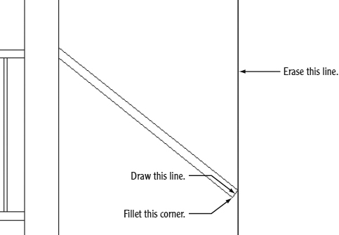
- Extend the upper line until it intersects the post on the left and the last remaining vertical line dropped from the floor plan.
- Extend the lower line only to the post on the left, as shown in Figure 10.30.
FIGURE 10.30 Finishing the stair rail
- Draw a line from the right endpoint of the upper-railing line, perpendicular to the lower line, and then fillet the corner.
- Erase the vertical line that extends from the floor plan (see Figure 10.30 shown previously).
- To create the posts, draw a line from the midpoint of a stair tread upward and then offset it 1″ (25.5 mm) to the left and right.
- Erase the original line, and then trim or extend the other two lines until they intersect with the lower-railing line.
- Using the top-right corner of each step as a reference point, copy the post to the other three steps.
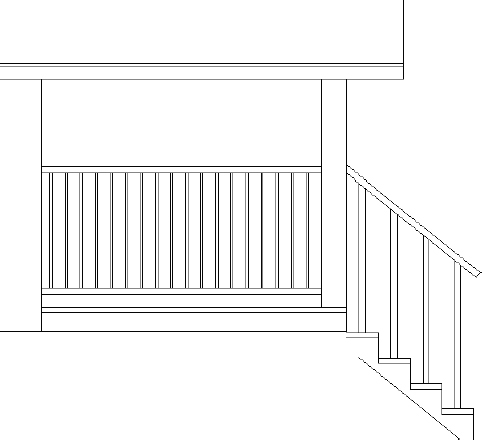
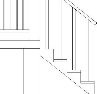
When you're finished, your deck should look like Figure 10.31.
FIGURE 10.31 The stairway, deck, posts, and railings
- Save the current drawing as I10-08-StairElevation.dwg (M10-08-StairElevation.dwg).
Drawing the Supports and Foundation
The cabin rests on a foundation, and the decks are supported by concrete posts. You can quickly draw these by using the Rectangle (RECTANG) command with object snaps and the Object Snap Tracking tool.
- Continue using I10-08-StairElevation.dwg (M10-08-StairElevation.dwg), or open it if it's not already open.
- Using the Layer drop-down, change the current layer to A-ELEV-FNDN from the Home tab Layers panel.
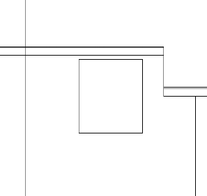
 Start the Rectangle (RECTANG) command, and draw a rectangle with its first point at the right end of the lowest horizontal deck line and the second point 1′ (305 mm) to the left and 2′-10″ (864 mm) below that point (in other words, at −1′,−2′-10″ or at −305,−864 mm).
- Extend the lower stringer line until it intersects the support post, as shown in Figure 10.32.
FIGURE 10.32 The extended stringer and the first deck support post
- Zoom out so that you can see the entire cabin, and start the Rectangle (RECTANG) command again.
- At the Specify first corner point or: prompt, click the lower-right corner of the cabin's exterior wall.
- At the Specify other corner point or: prompt, pause the cursor over the lower-left corner of the cabin's exterior wall until the temporary track point appears. Then move the cursor directly downward, and enter 18 (457).
The foundation rectangle is shown in Figure 10.33.
FIGURE 10.33 The completed foundation rectangle
- Save the current drawing as I10-09-SupportFoundation.dwg (M10-09-SupportFoundation.dwg).
Mirroring the Deck
From this view, the decks, stairways, post, and supports are nearly symmetrical, making the Mirror tool an excellent choice for creating most of the objects on the back deck. The front deck is wider than the back deck, but an efficient use of the ERASE and TRIM commands can quickly fix that.
- Continue using I10-09-SupportFoundation.dwg (M10-09-SupportFoundation.dwg), or open it if it's not already open.
- Start the MIRROR command, and then select all the components of the deck, stairs, railings, posts, and the concrete support.
- At the Specify first point of mirror line: prompt, use the Midpoint osnap to select the midpoint of the roof.
- At the Specify second point of mirror line: prompt, pick a point directly below the first point.
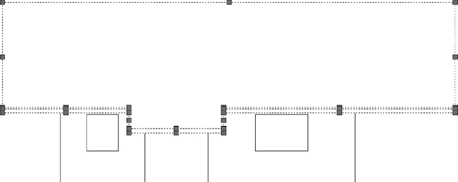
The components on the right remain ghosted, while the new components on the left appear solid, as shown in Figure 10.34.
FIGURE 10.34 The front deck mirrored to the back of the cabin
- When prompted whether to erase source objects, press to accept the default No option to retain the selected objects on the right.
- Zoom in to the back deck to clean up the mirrored linework by doing the following:
- Select any one of the vertical railing posts, and use the Item Count grip to adjust the number of railings so that they fill only the area to the left of the exterior wall.
- Trim the horizontal deck lines back to that wall line, including the line that overlaps the top of the foundation.
Try enabling Selection Cycling on the status bar to help you select the line that overlaps the top of the foundation.
Your back deck should look like Figure 10.35.
- Save the current drawing as I10-10-DeckMirror.dwg (M10-10-DeckMirror.dwg).
![]() WARNING Trimming the horizontal deck lines prior to adjusting the Path Array will open an Associative Path Array error dialog box. This dialog box is simply warning that your array extends beyond the length of the path (or in this case, line) that was selected when the array was created.
WARNING Trimming the horizontal deck lines prior to adjusting the Path Array will open an Associative Path Array error dialog box. This dialog box is simply warning that your array extends beyond the length of the path (or in this case, line) that was selected when the array was created.
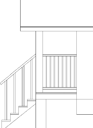
FIGURE 10.35 The back deck after trimming and erasing unneeded lines
Generating the Other Elevations
The full set of drawings that contractors use to construct a building includes an elevation for each side of the building. In traditional drafting by hand, the elevations were usually drawn on separate sheets. This required transferring measurements from one drawing to another by taping drawings next to each other, turning the floor plan around to orient it to each elevation, and using several other cumbersome techniques. You do it about the same way on the computer, but it's much easier to move the drawing around. You'll be more accurate, and you can quickly borrow parts from one elevation to use in another.
Making the Opposite Elevation
Because the north elevation shares components and sizes with the south elevation, you can mirror the front elevation to the rear of the building and then make the necessary changes:
- Open I10-10-DeckMirror.dwg (M10-10-DeckMirror.dwg), if it's not already open.
- Change the view to include space above the floor plan for the elevation on the opposite side of the building.
 Use the Pan tool, or hold down the scroll wheel, to move the view of the floor plan to the middle of the screen.
- Then zoom out the view enough to include the front elevation.
- Start the MIRROR command.
- Use a window to select the south elevation and then press .
- For the mirror line, select the Midpoint osnap and pick the left edge line of the ridgeline in the floor plan.
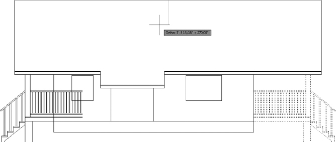
- With Polar Tracking on, hold the crosshair cursor directly to the right of the point you just picked (see the top of Figure 10.36) and pick another point. At the Erase source objects?[Yes/No]<N>: prompt, press to accept the default of No.
FIGURE 10.36 Specifying a mirror line (left) and the result (right)
The first side elevation is mirrored to the opposite side of the cabin (see the right of Figure 10.36). You can now make the necessary changes to the new elevation so that it correctly describes the south elevation of the cabin. However, you might find it easier to work if the view is right side up.
Take a look at the icon, currently located at the origin, for a moment. The two lines in the icon show the positive X and Y directions of the current user coordinate system (UCS). That is the world coordinate system (WCS), which is the default system for all AutoCAD drawings. You'll change the orientation of the icon to the drawing and then change the orientation of the drawing to the screen.
The UCS defines the positive X and Y directions in your drawing. A drawing can have several UCSs, but can use only one at a time.
The WCS is the default UCS for all new drawings and remains available in all drawings.
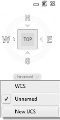
- Using the ViewCube found in the upper-right corner of the drawing area, click the UCS drop-down menu and select New UCS, as shown in Figure 10.37.
FIGURE 10.37 Creating a new UCS by using the ViewCube
- To rotate the current UCS 180° about the z-axis, type Z 180 at the Specify origin of UCS or [Face/NAmed/OBject/Previous/View/World/X/Y/Z/ZAxis] <World>: prompt.
This rotates the UCS icon 180° around the z-axis, to an upside-down position. The square box at the intersection of the x- and y-axes disappears, showing you that you're no longer using the default WCS (see Figure 10.38).
FIGURE 10.38 The UCS icon showing the UCS rotated 180°
- Start the PLAN command by entering PLAN at the command line and then C to select the Current UCS option.
The entire drawing is rotated 180°, and the mirrored elevation is now right side up. Note that the UCS icon is now oriented the way it used to be, but the square in the icon is still missing. This signals that the current UCS is not the WCS.
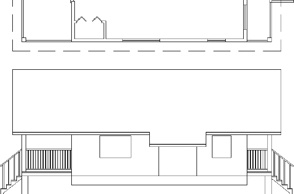
NOTE You used the UCS command to reorient the UCS icon relative to the drawing. You then used the Current option of the PLAN command to reorient the drawing on the screen so that the positive X and Y directions of the current UCS are directed to the right and upward, respectively. This process is a little bit like turning your monitor upside down to get the correct orientation—but easier. - Zoom in to the lower edge of the floor plan and the mirrored elevation (see Figure 10.39). Now you can work on the rear elevation.
FIGURE 10.39 The cabin drawing rotated 180° and zoomed in
- Save the current drawing as I10-11-0ppositeElevation.dwg (M10-11-0ppositeElevation.dwg).

Revising the New South Elevation
A brief inspection will tell you that the decks and stairs don't need any changes. The windows and roof need revisions, however, and the pop-out doesn't exist on this side of the cabin:
- The two remaining windows need to be resized and repositioned.
- The roof needs to be a series of straight, unbroken lines.
- The vertical pop-out lines and the pop-out roof extension need to be deleted.
You can accomplish these tasks quickly by using commands with which you're now familiar:
- Continue using I10-11-OppositeElevation.dwg (M10-11-OppositeElevation.dwg), or open it if it's not already open.
- Use the ERASE command to remove the following:
- The roof offset
- The walls for the roof offset
- The vertical lines from the remaining windows
After removing these lines, your elevation view should look like Figure 10.40.
FIGURE 10.40 Erasing the unneeded elements copied from the original south elevation
- Zoom in to the area where the roof extension was previously located.
The gap left after erasing the pop-out needs to be reconstructed.
 Start the JOIN command by choosing the Home tab extended Modify panel Join tool.
- Pick the top roofline at the Select source object: prompt, and then choose the adjacent top roofline.
- Press to end the command, and join the two segments into a single line segment.
- Repeat step 6 for the two remaining rooflines.
After you've joined each of the rooflines into three individual segments, your view should look like Figure 10.41.
FIGURE 10.41 Elevation view after repairing the lower roofline by using the JOIN command
- Change the current layer to A-ELEV-GLAZ by using either the Ribbon or the LAYER command.
- Using the Construction Line tool found on the Draw panel of the Home tab, create extension lines from the jambs of the two windows in the floor plan.
Once these are drawn, your elevation will look like Figure 10.42.
- Use the FILLET command to construct the new windows. If necessary, use Selection Cycling to aid in selecting the correct line when filleting the top of your windows.
Your elevation should look like Figure 10.43.
You need to save the UCS you used to work on this elevation so that you can quickly return to it in the future, from the WCS or from any other UCS you might be in. The default AutoCAD workspace does not include access to UCS commands. To access these UCS commands, you'll load an additional Ribbon panel to the View Ribbon tab.
FIGURE 10.42 Construction lines drawn from the floor plan windows to the elevation view
FIGURE 10.43 Use the FILLET command to construct the new windows.
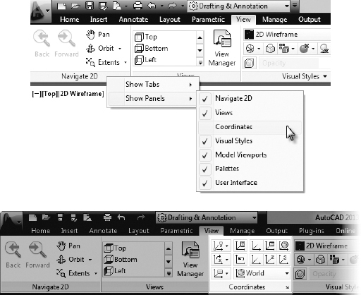
- Switch to the View Ribbon tab.
- Right-click the Navigate 2D panel title, and select Show Panels Coordinates (see the top of Figure 10.44).
The Coordinates Ribbon panel is now included within the View Ribbon tab (see the bottom of Figure 10.44).
FIGURE 10.44 Loading the Coordinates Ribbon panel (top) and the Coordinates panel loaded onto the View Ribbon tab (bottom)
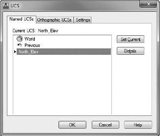
 Click the UCS, Named UCS button on the Coordinates panel of the View tab to open the UCS dialog box. Alternatively, you can enter UCSMAN at the command line.
- From the UCS dialog box, click the Named UCSs tab, and then click the current UCS name (currently named Unnamed) once to highlight the text. Then select North_Elev (see Figure 10.45).
FIGURE 10.45 The UCS dialog box
This will allow you to recall the UCS if you need to work on this elevation again.
- Click OK to exit the dialog box.
 TIP You can save any UCS in this way. The WCS is a permanent part of all drawings, so you never need to save it.
You can also save the view to be able to recall it quickly.
- Click the View Manager button in the View tab Views panel to open the View Manager dialog box, shown at the top of Figure 10.46. You can also start the VIEW command by typing V.

- Click New to open the New View / Shot Properties dialog box.
- In the View Name text box, enter North-Elev, as shown at the bottom of Figure 10.46.
- Click the Current Display radio button and click OK.
Back in the View Manager dialog box, North_Elev appears in the list of views.
TIP You can name and save any view of your drawing and then restore it later. - Click OK again.
Now you can restore the drawing to its original orientation, with the side elevation below the floor plan and right side up. You do this by restoring the preset Top view.
Use the In-Canvas Viewport Control toolbar found in the upper-left corner of the drawing area to restore the preset Top view.
- Click the View Controls menu (currently displayed as [Top]) from the In-Canvas Viewport Control toolbar, and select Top (see Figure 10.47).
This zooms to Extents view and displays a plan view of the drawing with the X and Y positive directions in their default orientation.
- Save the current drawing as I10-12-NorthElevUCS.dwg (M10-12-NorthElevUCS.dwg).
You created a new UCS as a tool to flip the drawing upside down without changing its orientation with respect to the WCS. Now you'll use it again to create the front and back elevations.
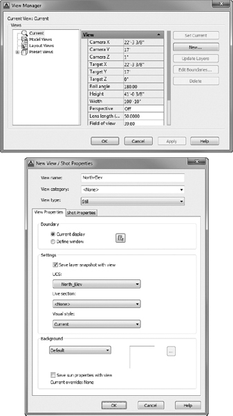
FIGURE 10.46 Saving a view in the View Manager (top) and in the New View / Shot Properties dialog box (bottom)

FIGURE 10.47 Restoring the preset Top view from the In-Canvas Viewport Control toolbar
Making the Front and Back Elevations
You can generate the front and back elevations by using techniques similar to those you have been using for the two side elevations. You need to be able to transfer the heights of building components from one of the side elevations to either of the remaining elevations. To do this, you'll make a copy of the first elevation you drew, rotate it 90°, and then line it up so that you can transfer the heights to the front elevation. It's quite easy:
- Continue using I10-12-NorthElevUCS.dwg (M10-12-NorthElevUCS.dwg), or open it if it's not already open.
- Zoom out slightly, and then zoom in to a view of the floor plan and the first elevation.
- Pan the drawing so that the floor plan and elevation are on the left part of the drawing area.
You need to transfer the height data from the side elevation to the front elevation. To ensure that the front elevation is the same distance from the floor plan as the side elevation, you'll use a 45° line that extends down and to the right from the rightmost and lowermost lines in the floor plan.
- Turn on Polar Tracking, and ensure that Increment Angle is set to 45°. Also make sure that the Object Snap Tracking button on the status bar is toggled on.
- Set the Endpoint osnap to running, and be sure the Midpoint osnap isn't running.
- Start the LINE command.
- Move the crosshair cursor to the bottom-right corner of the front stairway handrail in the floor plan. Hold it there for a moment.
A cross appears at the intersection point. Don't click yet.
- Move the crosshair cursor to the lower-right corner of the roof pop-out in the floor plan, and hold it there until a cross appears at that point. Don't click yet.
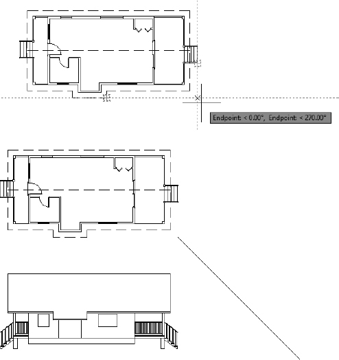
- Move the crosshair cursor to a point directly to the right of the corner of the roof pop-out and directly under the intersection point of the handrail (see the top of Figure 10.48).
FIGURE 10.48 Starting a diagonal reference line with tracking points (top) and the completed diagonal line (bottom)
Vertical and horizontal tracking lines appear and intersect where the crosshair cursor is positioned, and a small X appears at the intersection. A tracking tooltip also appears.
- Click to start a line at this point.
- Move the crosshair cursor down, away from this point and to the right at a negative 45° angle (or a positive 315° angle).
- When the 45° Polar Tracking path appears, enter 40′ (12200). Press again.
This completes the diagonal reference line (see the bottom of Figure 10.48).
- Start the COPY command, and select the entire south elevation and nothing else. Then press .
- For the base point, select the left endpoint of the baseline of the cabin.
- For the second point, pick the Intersection osnap, and place the cursor on the diagonal line.
- When the X symbol with three dots appears at the cursor, click (see Figure 10.49).
FIGURE 10.49 Using the diagonal line to find the extended intersection
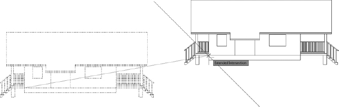
- Move the cursor to any point on the baseline of the south elevation.
An X appears on the diagonal line where the ground line would intersect it if it were longer (see the top of Figure 10.50). This is called the implied intersection: a distinct object snap in itself, and also the osnap that is used when the Intersection osnap is specified but an intersection is not clicked. This is why the three dots appeared after the X symbols.
FIGURE 10.50 Making a copy of the side elevation (top) and adjusting the view (bottom)
- When the X appears, click to locate the copy.
- Press Esc to end the COPY command.
- Zoom out to include the copy, and then use Zoom Window to include the floor plan and south elevations (see the bottom of Figure 10.50).
- Press Esc to terminate the COPY command.
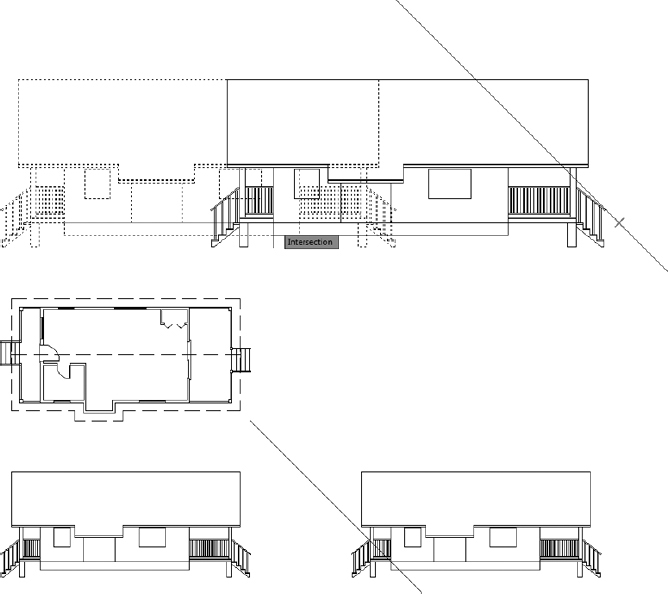
- Start the ROTATE command, and select the copy of the south elevation; then press .
- Activate the Intersection osnap, and click the intersection of the diagonal line with the baseline as you did in steps 13 and 14.
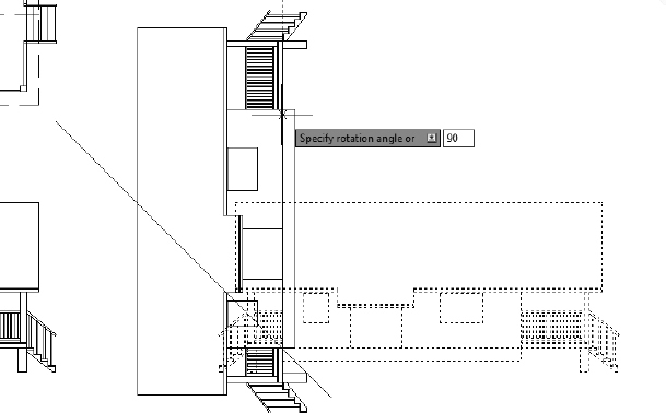
- For the angle of rotation, enter 90 (see Figure 10.51).
FIGURE 10.51 Rotating the copied elevation
- Start the MOVE command and, when prompted to select objects, enter P to select the most recently selected objects. The rotated elevation is selected.
- For the base point, click a point in a blank space to the right of the rotated elevation and on the upper part of the drawing area.
- For the second point, move the cursor down using Polar Tracking until the last step on the elevation is lower than the roof pop-out in the plan view. Then click.
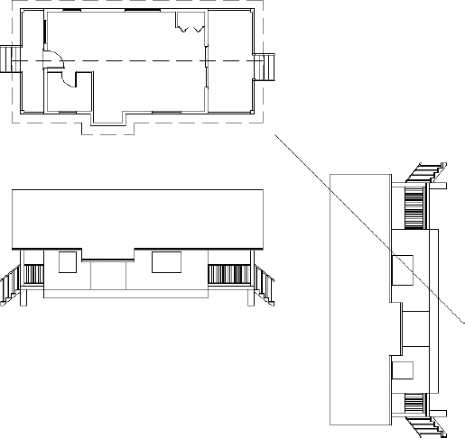
- Zoom out, and use Zoom Window to adjust the view (see Figure 10.52).
- Save the current drawing as I10-13-FrontElevProjection.dwg (M10-13-FrontElevProjection.dwg).
The rest of the process for creating the front elevation is straightforward and uses routines you have just learned. Here's a summary of the steps:
- Continue using I10-13-FrontElevProjection.dwg (M10-13-FrontElevProjection.dwg), or open it if it's not already open.
- Set up a new UCS for the front elevation showing the east side of the cabin:
- Drop construction lines from the floor plan across the drawing area and height lines. You will create these the copied elevation.
- Trim or fillet these lines as required, and add any necessary lines:
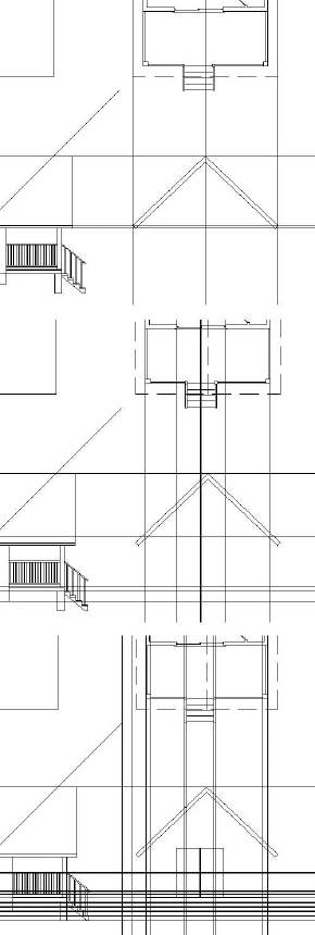
- Draw the roof first and remember that there is a thin layer of roof covering (see the top of Figure 10.53).
- Draw the wall, door, and foundation next.
You won't be able to get the height line for the sliding glass door from the side elevation. It's 7′-3″ (2210 mm) from the top of the deck (see the middle of Figure 10.53).
- Draw the pop-out, deck, and support posts.
The support post measures 1′-0″ (305 mm) across.
FIGURE 10.53 Incrementally drawing the front elevation starting with the roof (top); the wall, door, and foundation (middle); and finally the deck (bottom)
The railing posts have the same size and spacing on the front of the deck as they do on the sides.
- Copy the associative Array object from another elevation, and use the grips to adjust the Item Count.
This process can create a congested drawing, and you may want to draw the guidelines only as necessary to draw each component and then erase them. (See the bottom of Figure 10.53.)
TIP Although colors aren't visible in this book's grayscale print, it's good idea to “layer” your drawing when working with so many extension lines at once. Because each layer has a different color, assigning layers as you go will help you differentiate objects by color. - Erase or trim away any lines that represent objects that are visually behind any objects in the foreground.
For instance, do not draw two lines on top of one another in areas where the foundation is behind the steps or support posts or where the vertical door lines are behind the railings. Only draw the features you would see if you were standing at the front of your cabin.
- Make sure all the objects reside on the proper A-ELEV-… layer.
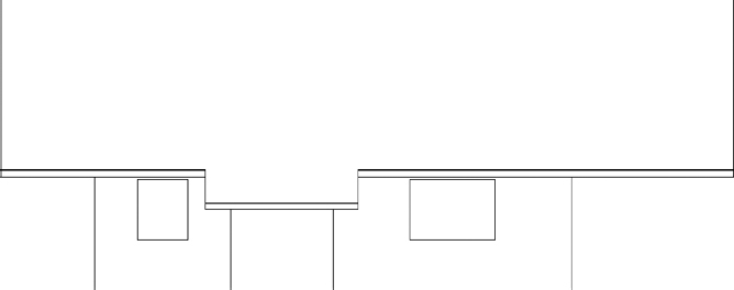
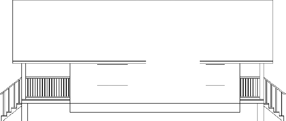
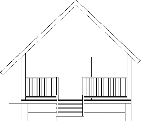
When you're finished, the east elevation should look like Figure 10.54.
FIGURE 10.54 The completed east elevation
- Erase the copy of the south elevation and the diagonal transfer line.
- Name and save the UCS and view (call them both East_Elev).
- Save the current drawing as I10-14-EastElev.dwg (M10-14-EastElev.dwg).
You can create the rear elevation from a mirrored image of the front elevation. Here are the steps:
- Continue using I10-14-EastElev.dwg (M10-14-EastElev.dwg), or open it if it's not already open.
SELECTION CYCLING
When creating elevations, you might accidentally draw a line over an existing line. To catch this error, take the following steps:
- Turn on Selection Cycling from the status bar.
- Move your cursor over the suspect line.
If more than one object exists in a given area, two blue boxes will appear in the upper-right quadrant of the cursor, as shown here:

- Pick the object, which opens the Selection dialog box.
- In that dialog box, cycle through each of the overlapping objects.
- Mirror the front elevation to the opposite side.
- Set up a UCS for the left elevation:
- From the ViewCube, click the UCS drop-down menu New UCS.
- Rotate the UCS 90° about the z-axis by entering Z 180 at the command line.
- Use the PLAN command to rotate the drawing to the current UCS.
Now you'll revise the elevation to match the left side of the cabin.
- From the ViewCube, click the UCS drop-down menu
- Temporarily move the railing posts a known distance and angle away from their current locations.
- Use the STRETCH command and Perpendicular osnap to stretch the stairway and railings to match the stairway location on the back of the cabin as shown on the floor plan.
- Move the railing posts back to their original locations.
- Adjust the associative Array objects to add or delete posts as required.
- Delete the sliding door frame that divides the left and right panels, and then adjust the door to match the extents shown on the plan view.
- Move the wall lines to the A-ELEV-WALL layer.
- Add the window with the lower edge at 2′-11″ (889 mm) above the baseline and the top edge at 7′-11″ (2413 mm) above the baseline.
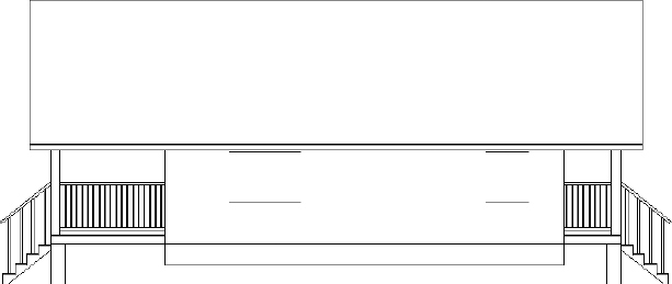
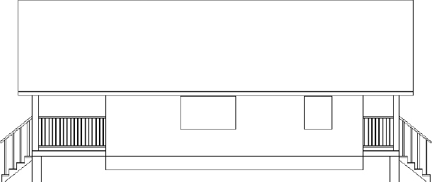
When you're finished, the elevation should look like Figure 10.55.
- Name and save the UCS and view (call them both West_Elev).
FIGURE 10.55 The completed rear elevation
When you have completed all the elevations, follow these steps to clean up and save the drawing:
- Return to the WCS: from the ViewCube, click the UCS drop-down menu and choose WCS.
- Display the plan view (PLAN command).
- Erase any remaining construction lines.
- Thaw the A-ANNO-TEXT layer, and then move the notes down and to the left so that they no longer overlap any elevation.
- Copy and rotate the FLOOR PLAN label under each of the plans, and edit the content appropriately.
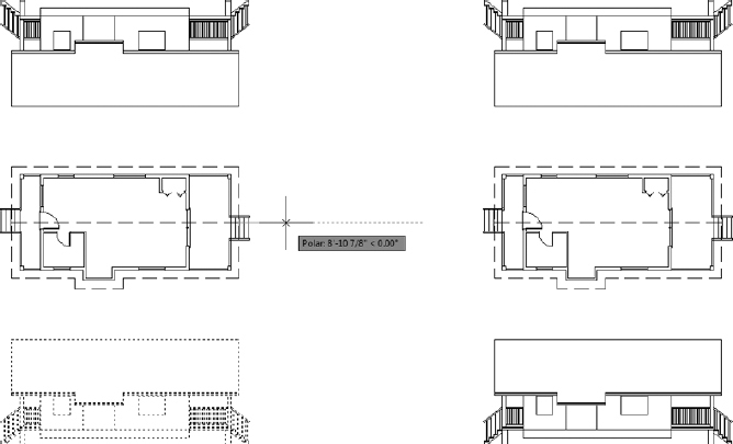
- Zoom out slightly for a full view of all elevations.
The drawing looks like Figure 10.56.
- Save the drawing as I10A-FPLAYO.dwg (M10A-FPLAYO.dwg).
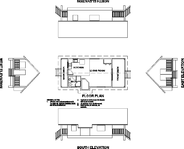
FIGURE 10.56 The finished elevations
Considering Drawing Scale Issues
This last view raises several questions: How will these drawings best fit on a page? How many pages will it take to illustrate these drawings? What size sheet should you use? At what scale will the drawing be printed? In traditional hand drafting, you wouldn't be able to draw the first line without answers to some of these questions. You have completed a great deal of the drawing on the computer without having to make decisions about scale and sheet size because, in AutoCAD, you draw in real-world scale, or full scale. This means that when you tell AutoCAD to draw a 10′ (3048 mm) line, it draws the line 10′ (3048 mm) long. If you inquire how long the line is, AutoCAD will tell you that it's 10′ (3048 mm) long. Your current view of the line might be to a certain scale, but that changes every time you zoom in or out. The line is stored in the computer as 10′ (3048 mm) long.
You need to make decisions about scale when you're choosing the sheet size, putting text and dimensions on the drawing, or using hatch patterns and non-continuous linetypes. (Chapter 11 covers hatch patterns, and Chapter 12 covers dimensioning.) You were able to avoid selecting a scale based on linetypes alone in Chapter 6, “Using Layers to Organize Your Drawing,” by setting all three LTSCALE variables to 1. Thanks to the flexibility this method provides, you were able to avoid committing to a scale so early in the project.
Instead you were largely able to postpone the scale decision until you began setting up your title block. At that point, you discovered that the largest scale that would allow you to keep the entire floor plan visible on a single sheet was about ![]() . That scale has a true ratio of 1:24, or a scale factor of 24. You'll get further into scale factors and true ratios of scales in the next chapter.
. That scale has a true ratio of 1:24, or a scale factor of 24. You'll get further into scale factors and true ratios of scales in the next chapter.
If you look at your I10A-FPLAYO.dwg (MI0A-FPLAYO.dwg) drawing with all elevations visible on the screen, the dashes in the dashed lines look like they might be too small, so you might need to increase the linetype scale factor. As you may recall, the easiest way to preview how the drawing scale affects linetypes is to change the annotation scale. This is possible because LTSCALE, PSLTSCALE, and MSLTSCALE are each set to 1.
Something else to consider is how the elevations you just drew will fit into your plotted plan set. If you were to thaw the title block's layer now, you would see that your elevations wouldn't all fit. Don't worry about that yet. Beginning with the next chapter, and right on through the end of this book, you'll need to make decisions about scale each step of the way.
Drawing Interior Elevations
Sometimes referred to as sections, interior elevations can be constructed using the same techniques you learned for constructing exterior elevations. You drop lines from a floor plan through offset height lines and then trim them away. Interior elevations usually include fixtures, built-in cabinets, and built-in shelves, and they show finishes. Each elevation consists of one wall and can include a side view of items on an adjacent wall if the item extends into the corner.
Not all walls appear in an elevation—usually only those that require special treatment or illustrate special building components. You might use one elevation to show a wall that has a window and to describe how the window is treated or finished, and then assume that all other windows in the building will be treated in the same way unless noted otherwise.
In the next chapter, you'll learn how to use hatch patterns and fills to enhance floor plans and elevations.
If You Would Like More Practice…
Here are three exercises for practicing the techniques you learned in this chapter. The last one will give you practice in basic orthogonal projection.
Exterior Elevations Open I10A-FPLAYO.dwg (M10A-FPLAYO.dwg), and revise each elevation by adding ![]() (38 mm) frames around the windows and doors. Add mullions, the dividers between windowpanes, to separate each window into four equal panes and add a rectangular window to the back door. Figure 10.57 shows the revised south elevation with the features added to the windows.
(38 mm) frames around the windows and doors. Add mullions, the dividers between windowpanes, to separate each window into four equal panes and add a rectangular window to the back door. Figure 10.57 shows the revised south elevation with the features added to the windows.
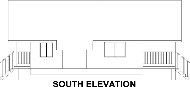
FIGURE 10.57 The revised south elevation
Interior Elevations For some practice with interior elevations, try drawing one or two elevations. You can measure the heights and sizes of various fixtures in your own home or office as a guide.
Orthogonal Projection Draw the three views of the block shown in Figure 10.58, following the procedures you used for the cabin elevations, except that, in this case, you'll use the procedure that mechanical drafters employ—that is, draw the front view first, and then develop the top and right side views from the front view. The completed drawing, named X10-00-OrthoProject.dwg, can be found on the book's website, www.sybex.com/go/autocad2013ner, or by visiting www.thecadgeek.com.
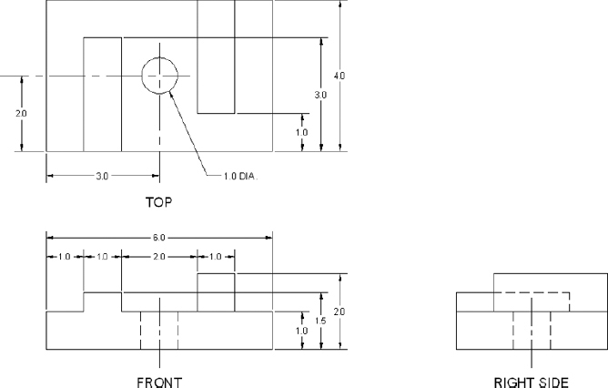
FIGURE 10.58 Front, top, and side views of a block