Exposure measurement
Strictly speaking, ‘giving the right exposure’ means making sure that your film receives the correct amount of image light (photons). In practice it is much more than this. Exposure can be used to give emphasis, by being correct for one chosen object in a scene, allowing other parts which are lighter or darker to be over- or underexposed. Exposure control is also the key to getting fine tonal qualities in your final pictures, whether prints or slides. And apart from its accuracy, the actual way you give exposure, via chosen permutations of lens aperture and shutter speed, has important side-effects on the image. As shown in earlier chapters, these strongly influence the appearance of things at different distances and the way that movement is recorded.
The exposure measuring and setting help provided by the camera itself varies considerably. At one extreme, a fully automatic compact will measure the light and instantly set controls according to an intelligent program, without even telling you what is going on. Total automation ensures a high percentage of accurate exposures with ‘average’ subjects, but takes many creative decisions out of your hands.
At the other extreme most view cameras offer no light-measuring facilities, and leave you all the decisions on shutter and aperture settings – often a slow business with the aid of a hand meter. The middle ground is catered for by cameras with manual (or semiautomatic) controls. Here you have to bear in mind the side effects of the settings you make but often use them to improve your shot.
This chapter looks at what ‘correct’ exposure means and what we should aim for using different films. It discusses equipment for measuring and setting exposure, their different modes of use, and how to avoid mistakes with problem subjects. Shooting with flash brings in its own exposure features, discussed towards the chapter end. Although film is featured throughout, most of these exposure topics apply equally to digital cameras too.
Factors that determine what exposure to give
The main factors that should be taken into account when you or your camera equipment measure exposure are:
On top of these come important interpretative considerations. For example, would it improve the picture to expose wholly for the brightest parts of the scene and make darker parts black; or expose for shadows and let light parts ‘burn out’? These judgements can only be made by you, and carried out perhaps using the camera’s exposure over-ride dial if it has one.
The exposure read finally has to be given to the film by a combination of:
• |
Intensity: the lens aperture. Bear in mind that this choice will affect depth of field, and to some extent definition. |
• |
Also Time: the shutter speed. This influences the way any movement of subject or camera will reproduce, and the spontaneity of expression or action. |
As Figure 10.1 shows, intensity and time – aperture and shutter – interrelate. Within limits (page 314), halving the intensity and doubling the time maintains the same total of photons of light energy reaching the film as would twice the intensity and half the time.
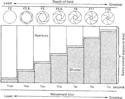
Figure 10.1 Aperture/shutterspeed relationships. Identical exposure can be given through a range of intensity/time settings. For example, each combination here will give the same light effect to the film. With a manual set camera you can choose between them, paying attention to depth of field and blur effects
Film manufacturers aim for a product which gives you good image quality; wide tolerance (to exposure errors, wrong colour lighting, etc.); and records the picture in such a way that it is easy to successfully print onto paper. But just what constitutes ‘correct’ exposure varies somewhat according to film type – monochrome or colour, negative or slide.
Black and white negatives
The more exposure a negative film is given, the darker the image tones in the processed result. Figure 10.2 shows how progressive increases in exposure makes all tones grow darker. Subject highlights, the term given to its lightest parts, are the first to become solid and lose their details. Then this quickly spreads to mid-tones and finally to shadows. You often find too that, when enlarged, grain is more apparent in overexposed negatives and general light spread throughout the emulsion reduces sharpness.
Going the other way, underexposure makes subject shadows reproduce so ‘thin’ they lose their detail, becoming indistinguishable from the clear film edge (‘rebate’). Then the same fate occurs to mid-tones, and finally to subject highlights too.

Figure 10.2 How exposure affects image appearance. In these three strips each image was given four times the exposure of the one to its immediate left. (A) is grossly underexposed and (E) is grossly overexposed. The subject is correctly exposed in (C). Top row: Colour negatives. Notice how shadow details become indistinguishable from clear film (‘off the toe of the curve’) in A. In E highlight detail and colours are choked
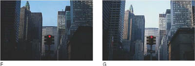
Middle row: Colour slide film. Being a reversal material underexposure (F) gives dark, detailless shadows which also lack colour. Overexposure (J) bleaches all but the subject’s darkest shadows
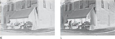
Bottom row: Monochrome negatives. Like the colour negative subject shadow details in K are missing – these areas will print as flat grey. Overexposed O has flattened contrast, midtones and highlights too dense
Results like these can be shown on a graph called a ‘characteristic curve’ for the film (see Figure 10.3 and Appendix D) with image light intensity values from shadows to highlights along the bottom axis (‘log relative exposure’) and final tonal density from palest up to darkest parts of the negative along the other. ‘Correct’ exposure should place all the image light intensities as densities on the lower part of the curve, yet not below the point where it flattens out, showing that densities are no longer separable and detail disappears.
The more contrasty your picture, the more accurate the given exposure must be – for it will then take less overexposure error to bring highlights into the state of being unacceptably dense, and less underexposure to make shadows too thin; see Figure 10.4. These conditions are said to offer least exposure latitude.
Colour negatives
A correctly exposed colour negative should meet requirements broadly similar to those for a black and white negative. However, it is even more important to avoid underexposure – empty shadows often print with a different colour cast, and since there is little choice of contrast grade with colour paper (see Advanced Photography) it is difficult to prevent thin negatives printing grey and flat. Processed colour negatives are also deceptive in appearance. The presence of the overall orange mask tint makes you think the image is denser than it really is. It may help if you assess negatives holding a piece of processed, unexposed film (as at the start of a film) close to your eye as a filter.
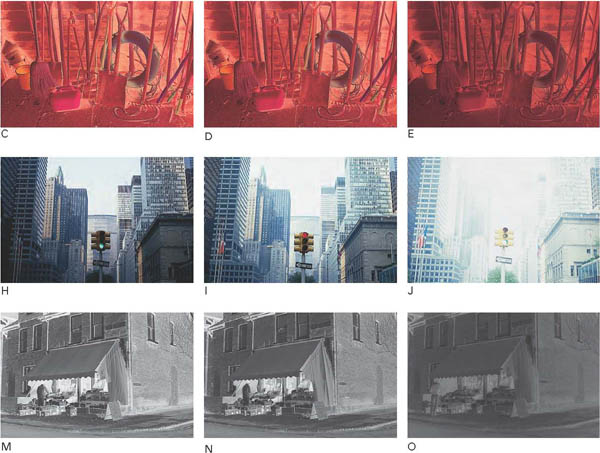
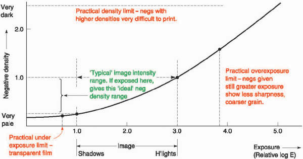
Figure 10.3 Characteristic curve of a monochrome negative film. Every image is a range of light intensities, so highlights are shown farther right than shadows on the exposure scale here. When an image is overexposed, its shadows-to-highlights values all shift right and so record as denser on the negative, although shadows may still just fall within the ideal range. When it is underexposed, values shift left showing resulting densities are too weak, although highlights may still be acceptable. Compare with Figure 10.2
Published data for colour negatives shows three colour-negative characteristic curves (Appendix C), one for each of the blue, green and red responding layers. If the film was exposed to light of the wrong colour balance without a correction filter one emulsion becomes effectively faster than another. Within reason this may be corrected by filters during colour printing. However, with a wide-tone-range (contrasty) scene, shot at incorrect colour temperature, it may even be possible for one of the emulsions to have underexposed low-contrast shadows while at the same time another has overexposed highlights. Printing will not correct the distortion this gives. So bear in mind that colour negative films when shot in lighting of the wrong colour have less exposure latitude than black and white negative films. Take several ‘bracketed’ exposures, see page 183.
Slides and transparencies – colour or black and white
Positive images on film are much easier to judge for exposure because you can make direct comparison with what you remember of the original scene. As Figure 10.2 showed, the more exposure you give these reversal-processed films, the lighter your result – with highlights especially becoming bleached of colour and tone. Underexposure has a darkening effect, particularly of subject shadows where colours eventually become engulfed in black. Of the two, overexposure is generally more objectionable than underexposure. This is partly because we tend to ‘read’ pictures by their light parts and accept dark shadows more readily than burnt-out highlights. Again, a slightly dense transparency is more acceptable for colour printing or scanning into digital form for printed reproduction than one where light parts of the image are literally missing.
The published characteristic curves of reversal materials (page 316) slope the opposite way to negative films, and have a steeper angle. In practical terms this means they are more contrasty, desirable in images that must look bright and rich in tone when projected as slides or displayed with back-lighting. However, such a characteristic means you have less room for exposure mistakes. Overexposure quickly bleaches your image’s highlights and pale areas into detailless clear film; underexposure brings its shadows down to detailless black. So slides and transparency materials demand more accuracy in measuring exposure – they offer less exposure latitude than regular colour or black and white negative films. And as with all films, this shrinks still further when the picture you are recording contains harsh, contrasty lighting.
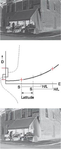
Figure 10.4 Exposure latitude. The amount you can alter exposure but still (just) get a negative which will give an acceptable print. The more extreme the difference between shadows (S) and highlights (H/L) in your image, the less latitude you have in exposing without exceeding ideal limits
‘Bracketing’ and clip tests
The simplest insurance against error, if circumstances permit, is to make several ‘bracketed’ exposures. With black and white film take one picture using the settings you expect to be correct, then shoot others giving half and twice this exposure. With colour negative film, bracket using closer increments, shoot one frame a half-stop underexposed, plus frames half a stop and one stop overexposed. For slides and transparencies, bracket at half stops too, but erring more towards underexposure than overexposure. If your camera has an exposure-compensation dial (page 192) the quickest way to bracket is by turning this to the required + or – settings. Better still for difficult scenes, several advanced 35 mm SLRs offer ‘auto-bracketing’. In this mode one pressure on the release exposes a burst of 3 or 5 frames at 2 frames per second, each at a different exposure setting. You pre-set the increments ranging from one-third to twice the measured ‘correct’ exposure.
Further modify your bracketing routine according to the exposure latitude. For example, a contrasty image (harsh lighting and/or a subject with strong inherent contrast) will give absolutely minimal latitude. You should therefore take more bracketed exposures with smaller differences between each. Reverse this approach if exposure latitude is exceptionally wide.
With most materials you can gain further protection by planning out all or part of one film as test exposures, to be processed and examined first. Use an extra magazine back, a separate 35 mm body or marked sheet-film holders to accumulate one extra anticipated ‘correct’ exposure of every subject you shoot during a day’s location work, additional to your main run of exposures. Process this test set of shots normally and check them to decide which, if any, films will need adjusted processing (page 216). Alternatively, make sure you include three bracketed exposures at the start of a 35 mm film or end of a rollfilm. These are then easily clipped off and test processed (a service offered by most professional labs) to decide any changes required for the remainder of your film.
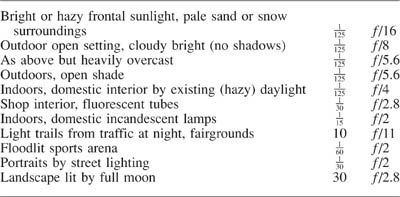
Figure 10.5 Simple exposure guide – for an ISO 100/21° film
Figure 10.6 The light-measuring cell of the meter built into a basic compact camera. This gives a direct, overall reading of your subject. (Take care not to obstruct it with your finger or the camera may overexpose)
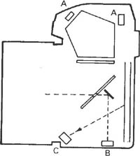
Figure 10.7 Various light measuring cell locations designed for through-the-lens metering in SLR cameras. A: viewing most of the image from above the SLR eyepiece or pentaprism. B: reading through a semi-silvered part of the mirror. C: reading light reflected off the shutter blind or film once the mirror has risen
Measuring exposure (continuous light)
Apart from checking tables, the normal way of finding correct subject exposure is by measuring with a hand meter or some form of light meter inside the camera. Learning how a hand meter is used will help you understand the more common internal meter, which was born from it.
Tables and guides. Never despise that simple table of recommended exposure settings packed with your film, see Figure 10.5. Some day your meter or camera may not be working. Another emergency routine to remember is the following:
Use one divided by the film’s ISO (arithmetic) speed as your nearest shutter speed. Then set f/16 for bright sun, or f/8 for cloudy-bright conditions or their equivalent, e.g. with ISO 100 film use 1/125 sec at f/8.
The trouble with tables and guides is that they deal with subjects and situations only in the broadest terms. Tables that try to be more comprehensive often end up becoming incomprehensible.
Using built-in meters – how they work
An exposure meter built into the camera has a tiny silicon light-responsive cell measuring your subject, or the image itself, and able to transfer its readout direct to aperture and shutter settings. In most compact cameras the cell faces the subject from behind a window alongside the lens or viewfinder. SLR cameras measure image light from behind the lens, so taking into account the image-dimming effects of close working, filters, etc., and of course adjusts how much of the scene it reads with any change of focal length.
Several cell positions can be used within an SLR body. One or more cells may view the image on the focusing screen (from above the pentaprism eyepiece, for example) while another below the mirror looks up towards the film. The ‘off the film’ (OTF) cell views the image as it appears on a reflective pattern on the front of the shutter blind, and on the emulsion itself after the mirror has risen and during exposure. This allows it to measure and control the period of a time exposure as it actually takes place, as well as flash exposures (page 196).
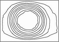
Figure 10.8 Exposure meter measurement area. ‘Contour lines’ show the relative distribution of light sensitivity across the picture format. Here the system is centre weighted – most influenced by subjects composed centrally
For most situations though light passing through a semi-silvered part of the main mirror is reflected downwards to light sensors located in the base of the camera (Figure 10.7). Advanced cameras have here a honeycomb or ‘matrix’ of ten cells or more arranged to measure different parts of the image area, giving them different priorities – more in the centre than the corners for example. And by selecting ‘spot’ metering mode only the very centre cells sample light, so you can measure from a small chosen area, Figure 10.10.
Usually you switch on the meter with a half pressure of the shutter release (it switches itself off later after a timed period). Some compact cameras have a lens and viewfinder shield you slide open to switch on the meter and unlock the shutter release. Output from the light-sensing cells feeds to an internal microchip central processing unit. This also receives information from other parts of the camera, namely the ISO speed read off the cassette and conditioned by any setting you made on the exposure compensation dial, the f-number set on the aperture ring, and/or the shutter speed chosen. The CPU instantly computes and typically sends control signals to aperture and/or shutter, as well as displaying the required settings alongside the internal focusing screen and on top of the camera body; see Figure 10.11.
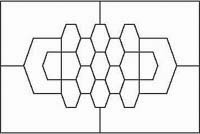
Figure 10.9 A multi-sensor chip located in the base of an advanced SLR. This evaluates image brightness based on 21 sampling areas. According to the mode you pick light measuring ranges from overall averaging to centre spot reading
To make full use of built-in metering it’s helpful to understand (a) the area of your picture being measured, and (b) the effect of different ‘modes’ your camera offers to translate light readings into shutter and aperture exposure settings.
Measuring area
Most meters built into compact cameras take a ‘centre-weighted’ averaging light measurement of your subject. This means that the reading is influenced more by central areas and least by the corners of the picture. Precise layout of this ‘sensitivity map’ (Figure 10.8) varies in different SLR cameras – some pay more attention to the bottom of the (horizontal) frame to reduce sky influence in landscapes. Overdone though, this creates problems in other, upright, pictures. Centre-weighted measurement is surprisingly successful, but you must still remember that largest areas of tone in your picture have greater influence than smaller areas. Learn to recognize your composition’s key tone, such as face skin tone in a portrait. Then if necessary make it fill up more of the frame just while the reading is taken; see page 188.
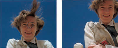
Figure 10.10 (right) Spot reading. In this mode you must carefully choose and align one or more subject areas you wish to read – in this case shadows and highlights within the marker on the focusing screen. Then average by making exposure settings for half way between the two readings
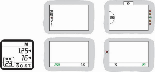
Figure 10.11 Some of the ways the settings made by a light reading are signalled in the viewfinder (or LCD body top panel, above) of different SLR cameras. Top row: Camera in aperture priority (Av) mode – the meter needle shows what shutter speed it has set. Far right: Manual mode – you alter either shutter speed or aperture, until OK signal (green diode) lights up. Below, centre: Alternative way of displaying (in green) the meter’s setting in Av mode. Below, far right: The same display when in shutter priority (Tv) mode. You set shutter speed and the camera now sets aperture. The red signal here warns of the risk of camerashake at 1/15 second
Advanced SLR systems measure by multi-segment (‘matrix’) metering, Figure 10.9. The various outputs from different parts of the frame are then compared against an in-built computer program based on thousands of subject field trials. ‘Fuzzy logic’ fills in gaps in the sampling process. Some cameras additionally offer you the option of spot metering, which measures only within the small area shown by a circle or rectangle in the centre of the focusing screen. You can then align this spot and get the camera to hold this reading. Or take separate readings of darkest and lightest key elements (Figure 10.10) and the metering system averages between the two. See also Spot meters, page 191.
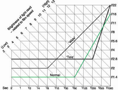
Figure 10.12 Typical exposure auto-program for a camera with f/1.4 standard lens. Working from top to bottom of the green graph line, as scene brightness drops (the exposure needed increases) the program progressively widens the aperture and slows the shutter speed. Note speeds safest for hand-holding are retained until f/1.4 is reached. Camera may signal ‘shake’ or ‘use flash’ at 1/30 second and slower. If you select ‘Tele’ program instead (shown here for a lens of f/2.8 maximum aperture) shutter speeds of 1/250 second or faster are held as long as possible. ‘Wide’ program (f/2 lens) pays equal attention to aperture and shutter changes
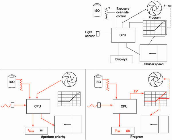
Figure 10.13 Right: the main components in a multi-mode exposure setting system built into a camera. Below left: set to ‘aperture priority’ mode. Light reading, film speed and your chosen f -number are input, and the CPU translates this data into the correct shutter setting. Your aperture and the camera’s chosen shutter speed are also displayed. Below right: set to ‘program’. The CPU inputs light and ISO data, outputs a figure to a program (see Figure 10.12) which then sets the most suitable shutter/aperture combination
Fed by the light measurements and the other exposure information it needs, the camera’s CPU makes its choice of settings in various ways, according to ‘mode’. Some cameras offer only one (typically autoprogram) mode, others a choice of four or five that you select according to shooting needs and personal choice. Each offers its own advantages.
So-called manual mode is the most basic and flexible arrangement. You turn the camera aperture and/or shutter speed controls, and the meter signals when a combination will give correct exposure. For instance, you can set the shutter to 1/125 second (for hand-holding) then change apertures until a signal – usually a green diode beside the focusing screen – lights up. Or you could set f/16 to maximize depth of field and then change shutter speeds until the same OK signal is given. Often manual mode also allows you to over or underexpose the shot you are taking half or one stop by working to a different coloured signal; see Figure 10.11. However, this system requires longer to set correct exposure than any other mode.
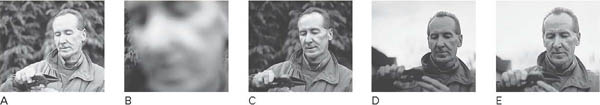
Figure 10.14 Conditions which often fool a general or ‘centre-weighted’ exposure reading. Although the figure in all these pictures received the same lighting, in A the large area of dark background causes the meter to give a low reading and so make settings which overexpose the face. Coming in close (B) and reading only off the face ensures correct portrait exposure (C). Similarly (D) a bright background leads to underexposure of the face unless you take a close-up reading to get result (E). Working with an auto-exposure camera AE lock must be applied, see text
Aperture priority (Av) goes a step farther – saving time if you must work at a particular aperture, perhaps after having checked depth of field with the lens preview button depressed. In this mode you set the aperture and the camera automatically sets the shutter speed required for correct exposure. The arrangement can be very helpful for closeups, where depth of field is critical; also for night-shot time exposures (most cameras can set up to 30 seconds or so). This mode will also handle a very wide range of light-intensity conditions, since cameras offer far more potential shutter settings than f-numbers. However, you may easily discover that you are hand-holding the camera at a slow shutter speed, resulting in blur.
Shutter priority (Tv) mode works the other way around. You set shutter speed and the camera selects what f-number the lens aperture will close to when you take the picture. (As with most modes, a signal warns if the exposure required is over or under the setting range available to the camera, in which case you should set a different shutter speed.) Shutter priority is useful for sports work and any action or interpretative photography where you must maintain control over the appearance of movement. Or it may be just that you prefer to shoot a hand-held series at a safe 1/125 second, or 1/250 second with a longer lens, and accept whatever depth of field lighting conditions permit.
Programmed modes allow the camera to take over both shutter and aperture settings, running through an intelligent program – from shortest time/smallest aperture, to longest time/widest aperture, according to inputs of light reading and film speed (shown in Figure 10.12 as Exposure values). The chart illustrates a typical standard lens program in which there is a progression of both shutter and aperture changes until, with decreasing light, the lens’s widest aperture is reached (in this instance f/1.4). From here onwards exposure time only increases, usually accompanied by a camera-shake warning light at speeds slower than 1/30 second.
Programs like this are often built into compact cameras as hidden systems which do not reveal to the user any technical information other than giving ‘shake’ and ‘out of range’ warnings. They are sufficiently effective for most amateur photography subject conditions.
On SLR cameras, however, having one standard program may not be suitable when you use telephoto or wide-angle lenses. Some cameras therefore offer two additional programs – ‘tele’ and ‘wide’. As Figure 10.12 shows, on tele the camera reacts to decreasing light by maintaining fast shutter speeds as long as possible, to counteract the ever-present risk of image blur with long-focal-length lenses. When wide is selected the camera makes equal alternating changes of aperture and shutter speed, bearing in mind that camera shake is less likely. This choice of program is either left to the user, or may be selected automatically when you fit on a telephoto or wide-angle lens.
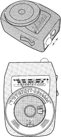
Figure 10.15 Hand meter. Top: A light-sensitive cell behind a circular window in the centre of the front end gives general, reflected light readings. The white plastic dome slides over this window for making incident-light readings: Bottom: The large calculator dial must be programmed for film ISO speed. The numbered light reading shown by the needle is next set in the ‘SCALE’ window. You can then read off shutter settings against f-numbers at top of dial
In practice, having a multi-mode AF camera will probably mean that you rarely use more than two or three of these options. The most popular modes tend to be manual and aperture priority. A fully auto program is handy for rush situations, while shutter priority is preferable if you do much action-freezing photography or use telephotos handheld. In all modes it’s helpful if the camera displays what lens and shutter settings are made, to allow you to pre-visualize and if necessary over-ride the effect of aperture and shutter on picture appearance.
TTL meters that are built into rollfilm cameras or form add-on accessories to view cameras are less comprehensive than 35 mm types. Most rollfilm SLRs, for example, offer a system providing centre-weighted measurement and a choice of either manual or aperture-priority setting modes. A TTL meter for view cameras (Figure 10.18) uses a probe you move around the image plane to make spot readings. However, for the most part medium and large format cameras are still used in conjunction with a separate, hand-held exposure meter.
Using a hand-held exposure meter
These are the oldest ‘photoelectric’ measuring aids, but in modern form still used today, mainly by professionals working with large or medium format cameras. A typical basic meter (Figure 10.15) is a self-contained unit with a small light-responsive silicon photocell (SPC) or a cadmium sulphide (CdS) cell behind a window. This sensor forms part of a circuit including a battery and current-measuring device.
Essentially you programme the meter with the ISO speed of your film, point it towards the subject, and read off the exposure required. To do this last part you note the number picked out by a needle moving over a scale, and set this against a pointer on a large dial. The dial lines up a complete series of f-numbers against a series of shutter speeds. Each will give correct exposure – you are left to choose any of these paired settings according to depth of field and image movement considerations. Other meters do away with moving parts – you feed in either the f-number or the shutter speed you want to use, then a liquid crystal display on the meter shows the appropriate shutter speed or f-number with which they should be paired.
Reading the light
There are several ways to take readings with a hand meter, according to working conditions and personal preference. These are: (1) a general or ‘integrated’ reading of the subject, (2) two or more ‘brightness-range’ readings of the subject, (3) a greycard reading, or (4) an incident-light reading of the light source. (Methods 1–3, which all measure reflected light, can also be carried out with a TTL camera meter.)
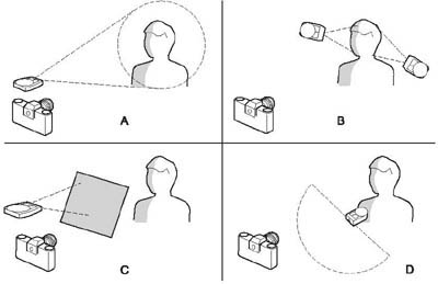
Figure 10.16 Alternative methods of using a hand meter: A: direct, general reading from the camera. B: close separate measurements of lightest and darkest important areas, then averaging the two light readings. C: reading off a mid-grey card receiving the same lighting as your subject. D: incident-light reading through the meter’s diffusing dome. Meter here points from subject towards camera
1 |
For a general reading, you just point the meter from the camera towards your subject. The meter’s angle of view usually approximates that of a standard lens, so it ‘sees’ a matching area of the scene. The meter averages out all the various light values this contains (naturally being more influenced by the values of large subject areas than small ones). Then it gives an exposure reading that would place this single imaginary ‘average brightness’ about midway between under- and overexposure on the characteristic curve. Like using a compact camera with an overall reading meter, the trouble with a general reading is that the most important element in your picture is not always the largest. The face in a portrait may occupy less than 50 per cent of the picture area, the rest being background (Figure 10.14). In one version you might use a dark background and in another a much lighter one, without any change to the illumination on the face. Yet the meter, taking over 50 per cent of its reading from the background in each case, will give low reading for the first shot and so overexpose face skin tones, and a high reading for the second version making the face underexposed. A general reading is therefore only satisfactory if your shot has a fairly equal distribution of light and dark areas in which you want detail. Subjects like Figure 10.19 (top), for example. It often works with softly lit landscapes (tilt the meter down slightly to read less sky and more land, if this is where details are more important). Another problem is that zooming or changing to a different focal length lens can make camera and meter have very dissimilar angles of view. Used from the camera position the meter then reads a larger or smaller area than is included in your picture. |
2 |
For a brightness-range reading, you first decide which is the lightest and which the darkest part of the scene where detail must still just record. Take separate readings of both, bringing the meter sufficiently close in each case to exclude everything else. (Don’t cast a shadow on to what you are measuring, however.) You next split the difference between these light measurements and read off exposure for the resulting figure. Brightness-range readings therefore make the best possible exposure compromise between subject extremes, and also remind you how much contrast is present. If shadows require over 6 stops more exposure than highlights consider reducing lighting contrast by adding a reflector or flash, or wait for changing conditions, or alter your viewpoint. Last resort, be prepared to accept loss of detail at one or other end of the scale, and pick which is least objectionable. The trouble is that two readings take longer than one and you may not be able to approach parts of the subject close enough (but see substitute readings, page 193). |
3 |
For a grey-card reading you measure from a mid-grey card, held so that it receives the same light as your subject. (Kodak make a standard 18 per cent reflectance card for the purpose.) Exposure given according to this one reading should coincide with the average of darkest and lightest areas. You must use a card large enough to fill the meter’s field of view (Figure 10.16), and avoid casting a shadow on it when reading. Carrying a card is not very practical on location, although it may suit studio work, particularly copying; see page 193. |
4 |
For an incident-light reading, the hand meter has a white plastic diffusing dome which covers its measuring window. Then you hold the meter in the same lighting conditions as the subject, pointing towards the camera. It therefore takes into account all the (scrambled) light reaching the subject, rather than the subject’s reflective properties. The plastic dome transmits 18 per cent of the light, so you end up with much the same situation as a greycard reading, but in a more convenient form. Enthusiasts for incident-light metering point out it is simpler and less likely to give overexposed highlights than most other techniques, so it is especially suitable for reversal films. |
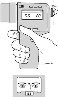
Figure 10.17 A spot meter. The eyepiece shows you part of your subject magnified, a centre circle marking the light measuring zone. Having programmed ISO film speed and shutter setting, the meter signals the required f -number
Spot meters
A spot meter, Figure 10.17, is a telephoto version of a reflected-light meter. It has an eyepiece for aiming the meter from the camera position. Inside you see a magnified view of part of the subject, with a small measuring area outlined. The meter’s angle of view over this area is typically only 2–3°. Having set your film’s ISO speed, you press a trigger-like button to get a reading, and the exposure settings are displayed inside and/or outside the meter. Spot meters are extremely convenient for taking brightness-range readings if you cannot easily approach your subject, and when shooting close-ups. However, you can get totally inaccurate exposures if you don’t carefully consider which subject parts to sample.

Figure 10.18 An add-on meter for a 5 × 4 in view camera. This is carried on an open frame the ame size as a film holder. The movable probe then allows selective ‘spot’ readings from any chosen parts of the picture area
Conditions hand meters do not consider
All the above methods of meter-reading exposure for a subject should give you the same result, if used properly. Bear in mind though that a hand meter does not take into account:
• |
Close-up focusing conditions. Increasing the lens-to-image distance to focus sharply a close subject makes the image dimmer. Inside the camera, this is like moving a projector farther away from a screen (the film). The projected image grows bigger but less bright, following the rule that twice the distance gives twice the image size and one-quarter the light over the film area. You must therefore increase the exposure the hand meter suggests, as near as possible by the factor shown in Figure 10.23. (Increases here are based on the formula shown in Appendix A.) |
• |
Use of filters. Most filters used over the lens cut down the light, so increase the exposure shown on the hand-meter by the factor printed on the filter rim or quoted by the manufacturer. Remember with colour filters that this factor may alter with the colour of your subject lighting together with the film’s colour response. Read the data sheet in with your film. An unknown filter factor may be checked by comparing readings with and without the filter in front of the meter. With strong colour filters however the response of some measuring cells slightly mismatches film colour sensitivity and so creates variations. |
• |
The effects of exceptionally long or short exposure times. As with internal meters, hand meters don’t take account of reduced film sensitivity when long exposure times are given. See reciprocity failure, page 314. |
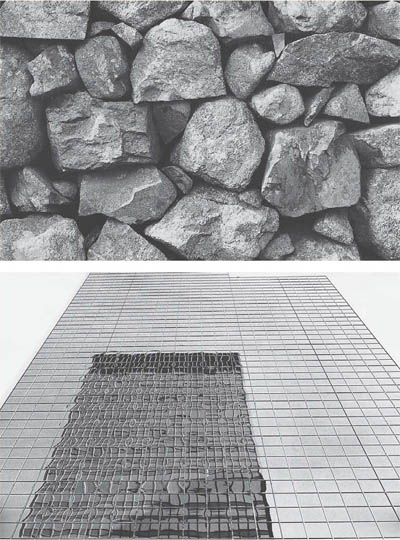
Figure 10.19 Top: This sort of subject – with more or less even distribution of light, dark and midtone areas – is ideal for exposure reading by either general or centre-weighted measurement. Bottom: In this shot the most important element is the distorted reflection, occupying only about 25 per cent of the frame. A general reading here would underexpose the reflection. It is better to take a spot reading off the reflected building, or briefly recompose it to completely fill the frame while taking a general or centre-weighted reading. (If necessary set Exposure Lock to stop the camera reverting to a faulty measurement when you finally recompose to shoot)
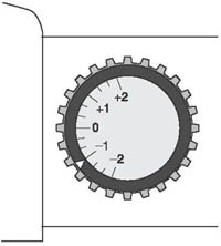
Figure 10.20 Exposure over-ride dial, on camera body. As shown here all pictures will receive half the exposure the camera would normally set
Point-and-shoot cameras apart, an exposure measuring system (built-in or hand-held) allows you choices and control at three main points: (1) the ISO speed set for the film, (2) the parts of the subject you actually measure, and (3) the alternative ways of dividing exposure between lens and shutter.
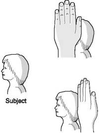
Figure 10.21 Making a substitute reading off your hand, for a distant face. Both must be in the same lighting. By turning your hand you can match both lightest and darkest parts, and so make brightness-range readings
If you must get more sensitivity out of the film in dim light, or subject contrast is very flat and needs a boost, try uprating. This means raising the film-speed figure (or using a ‘minus’ setting on the exposure-compensation dial on auto-setting cameras). In both cases you then follow this up with extra development. Take care to use a film the makers describe as suitable for uprating treatment. Another reason for setting an inflated figure is as a temporary measure just to get meter response in dark conditions.
Downrating or use of ‘plus’ compensation helps to reduce contrast and grain when followed up by reduced development. This applies principally to monochrome films, it is unwise to downrate and hold back colour films beyond one stop, see page 216. Downrating alone is a way of compensating for subjects measured by general reading against the light or with large bright backgrounds, which you know will otherwise result in settings which make them underexposed. Or you might use it to allow for a film’s anticipated reciprocity failure when given a long time exposure (page 314). Consider your plus or minus settings on the exposure-compensation dial as a lighten/darken device for purely creative purposes too, like the controls on many instant-picture cameras.
Always think carefully about what area(s) of the subject you measure. Decide the priorities between various tones of your picture. If there is only one really key tone, and the camera does not have spot reading, try to make it fill up the whole frame. With a close-up you can do this by just moving forward (don’t refocus – extra extension may change the reading). If your key subject is inaccessible, take a substitute reading from something convenient that matches it in tone. The eye is good at judging comparisons. A grey card has already been suggested, but you can read off your hand, lining it up and turning it at angles in the light to match a far subject tone (Figure 10.21), or find some part of the ground or sky with the right-looking tone.
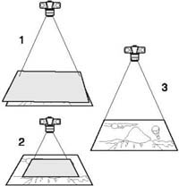
Figure 10.22 Using a grey card to read exposure when copying drawings. (1) covering the whole subject imaged by the camera. If the original is larger than your card, move your camera closer (2) until the card fills the frame. But don’t refocus, or cast shadows. (3) Finally keep to the exposure settings made, remove the card, and copy the whole drawing
It sometimes helps to carefully ‘redistribute’ your framing of the image making the size of each tone area relate to its exposure importance. For example, twisting the camera may just include the lightest and the darkest important tone 50:50 in the frame, so your one reading averages the two. Make exposure settings and then re-compose your shot as you want it.
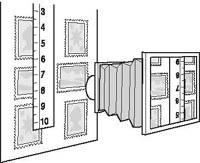
Figure 10.23 Close-ups shot using a camera without TTL metering need additional exposure. See table, right. To measure magnification, have a ruler alongside your subject. Divide this into its image size shown on the focusing screen
Magnification (Subject height divided into the height of its image) |
Increase exposure by: |
0.3 |
× 1.7 |
0.5 |
× 2.3 |
0.7 |
× 2.9 |
0.8 |
× 3.2 |
0.9 |
× 3.6 |
1.0 |
× 4 |
1.3 |
× 5.3 |
1.5 |
× 6.3 |
1.7 |
× 7.3 |
Copying line drawings, photographs, paintings, etc., often brings problems over how best to take a reading. Areas of dark and light are unlikely to be equal. Sometimes you can ‘home in’ on a midtone of sufficient size in a photograph or painting, but the best approach is to read off a grey card (or take an incident-light reading). You can see how important it is when using a built-in metering system, that it allows you to take a reading and then retain the settings unchanged after reframing the picture, removing the grey card, and so on. You will have to activate an ‘auto-exposure lock’ (AE-L) button on some cameras, otherwise the meter goes on taking new measurements.
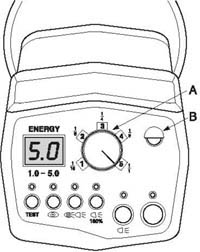
Figure 10.24 The control panel on the back of a small monobloc type studio flash-head. A: Flash power control. Allows full (250 Ws) or four fractional levels of flash. B: IR/light sensor. Acts as a slave trigger
A more specialist problem concerns exposure reading when using a moving light source to ‘paint with light’ an architectural interior or stilllife, spreading the light and forming a softer, more even source, page 123. Provided the lamp is moved in an arc maintaining the same subject distance throughout the exposure, you can accurately read the light when it is still.
Whatever your technique for measuring the light, deciding the best way to deliver the exposure by means of aperture and shutter controls is always something of a balancing act. Each shot has to be considered on its depth versus movement merits. Occasionally, requirements and conditions work together to give plenty of options, as with a scenic landscape with all its elements static and distant, in strong sunlight. At other times, they all conspire against you, as in a dimly lit shot of moving objects at different distances which must all record in detail. In this instance you must think how to improve conditions – perhaps by adding (flash?) lighting, altering camera viewpoint to reduce the range of distances, or uprating or changing to faster film but still keeping within grain and sharpness tolerances.
Getting exposure correct when you light by electronic flash (page 117) differs in several ways from continuous light source techniques. Basically, when a flash unit is switched on, a steady current is drawn into electrical ‘storage tanks’ which cause a ‘ready’ signal to appear when fully charged. Firing the flash allows this stored power to discharge as a pulse through gas in the flash tube and so produce the light. Then the unit recycles (recharges) itself ready for the next shot.
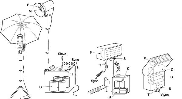
Figure 10.25 Flash equipment. Studio units and add-on portables, showing light sensor and synchronized firing controls. Power comes from batteries (B) or (studio units) household supply which charges capacitors (C). These discharge through flash tube (F) when the circuit is closed by camera synchronizing connections, test button (T) or light-sensitive slave. M: tungsten modelling lamp. S: sensor, measuring the light off the subject and self-regulating the duration of flash
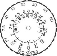
Figure 10.26 Simple exposure calculator dial based on distance × f/number, for a flashgun with a guide number of 36 (metres)
A harmless, low-voltage circuit is used to actually fire the flash, either (a) directly, through contacts that come together in the camera shutter or a test pushbutton on the flash unit, or (b) indirectly by means of a trigger that immediately responds to light from another flash, or even to sound or some other stimulus. Electronic flash goes off instantly when fired, its light duration ranging from about 1/500 to 1/30,000 second according to type and conditions of use. So provided your shutter is synchronized to have the image reach the film at this moment, it is primarily the flash that determines exposure time, rather than the shutter itself.
You can use flash at any shutter speed with a between-lens shutter; similarly with a 35 mm focal-plane unit, provided your flash always delivers a ‘long peak’. Most guns give a flash of shorter duration, and when these are used with a focal plane shutter at its fastest settings the blinds or blades block out part of the picture (Figure 4.8). This is why the shutter’s fastest ‘safe’ speed often has a different colour on the setting scale, or is marked ( ![]() ) or X. On programmed cameras this speed (or slower) is automatically set when you switch on the dedicated flash unit.
) or X. On programmed cameras this speed (or slower) is automatically set when you switch on the dedicated flash unit.
Some older shutters, such as between-lens types on view cameras, have an ‘X/M’ selector switch near the flash synchronization lead connection. This must be set to X.
With any camera you can always use an ‘open flash’ firing routine too, provided your subject and camera are static, and any ambient light around is quite weak. Open flash involves holding open the shutter on ‘B’ and firing the flash by its test button. Several repeated flashes can be given this way if your flash equipment is not powerful enough for the aperture you need to use.
Working from guide numbers
The most basic way to estimate flash exposure is to use the guide number (or ‘flash factor’) quoted for the unit. The GN is the distance between flash and subject, multiplied by the f-number required, when using film of a given ISO speed. Unless otherwise stated, figures are always quoted for ISO 100/21° film, and for distances in metres. So using a flash with a 36 guide number you set f/8 for a subject 4.5 m (15 ft) from the flash, or f/11 for 3.3 m (12 ft), using ISO 100/21° film. This might be built into a calculator dial like Figure 10.26, which can also include other film speeds and the use of the flash at fractions of full power, if this is possible. Self-regulating flashguns set to ‘manual’ work with a similar kind of calculator or table. Guide numbers are also quoted to compare the output of different flash units.
The much greater power output of studio flash units is more frequently quoted in ‘watt-seconds’ (= joules). The guide number of a typical 1500 W/s power pack unit is 160 (metres) using the head with a bare tube and reflector. This ratio varies with the head design, GN often being reduced to one-fifth when the same head is set behind the diffusing material of a softbox, for example; see Figure 7.15. Studio flash working from a generator (power pack) can also feed several heads, in which case output is divided by the number of equal power heads.
Disadvantages. In practice guide numbers alone do not take sufficient account of the reflective properties of your particular subject and its surroundings, and whether flash is direct, bounced, diffused by softbox or colour filtered. Also the manufacturer-quoted number tends to apply to favourable conditions, such as direct lighting of a pale-skinned person in a small room with pale-toned walls!
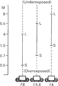
Figure 10.27 Self-regulating flash. Distance S to L shows the selfregulating working range of a typical small flashgun (set for ISO 100/21°) at various apertures. S: shortest flash duration. L: longest duration
Using a self-regulating flash
Battery flash units – add-ons or built into the camera – mostly incorporate their own exposure reading system. In an add-on gun, this typically consists of a fast-acting sensor set behind a small window on the main body of the unit, facing your subject. The sensor has an angle of view of about 20°, and so reads the flash illumination reflected back from everything within the central area of your picture. The flash gun has to be set for the ISO film speed and the f-number you intend to use.
In the case of a compact with built-in flash the camera’s own next-to-lens light sensor may act as the flash sensor, and is already fed with ISO speed and aperture information. (Alternatively autofocus cameras set aperture based on subject distance measured by the AF system, simply working to a guide number.)
According to the light received back from the subject, the unit instantly regulates flash duration to give correct exposure. For example, it might clip flash to 1/30,000 second if the subject is close or bright and therefore gives a strong light reading, or extend it to full (typically 1/500 second) duration with a distant or dark subject.
The range of subject distances over which a self-regulating flash will maintain correct exposure is reasonably deep, but as Figure 10.27 shows, the wider the lens aperture set, the farther the working range moves away from the camera. Distances double for every two stops’ change of aperture, as with guide numbers. Most of the time a setting about midway in the f-number scale gives a good working range unless you are shooting from very close or far away. With the exception of smallest units, electrical energy is returned to storage when shorter flashes are used. The shorter the flash the less time you have to wait for it to recharge.
Disadvantages. Although a self-regulating unit is a quick, convenient way to control exposure, its method of measuring light reflected from your subject is fairly crude. It is over-influenced by the relative areas of light and dark objects within your picture, like any other general reading meter. Also the constant angle of view measures a larger or smaller proportion of your picture area if you use tele or wide-angle camera lenses. When shooting close-ups, no account is taken of light loss in the camera system owing to close focusing conditions (page 191).
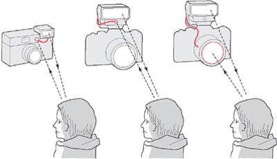
Figure 10.28 Three forms of selfregulating flash exposure control. Left: A compact camera’s light sensor beside the lens measures and controls the duration of its built-in flash. Near right: similar sensor system within a clip-on gun (must be programmed for ISO and aperture set). Far right: the same gun, if dedicated to the particular SLR, uses the camera’s ‘off-the-film’ exposure reading circuit instead
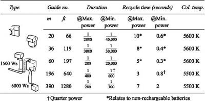
Figure 10.29 Comparing light-output and performance. A cross-section of commercial flash units, from a small unit built into a compact camera, to powerful, generator type studio equipment
SLR dedicated flash systems
A ‘dedicated’ flash takes self-regulation one important stage farther for SLR cameras. Multi-circuits between a suitable add-on flashgun and camera allow them to communicate with each other. As long as the camera has TTL exposure measurement ‘off the film’ this internal metering takes over the role of the flash unit’s sensor, with the bonus of automatically taking into account f-number, ISO speed, close-up imaging, filters, etc. You also have use of the camera’s exposure-compensation dial to cope with difficult subject conditions. The SLR camera’s focusing screen of course shows how much subject is being measured, whatever the lens focal length. The flashgun may, in return, communicate data such as ‘charge ready’ and ‘exposed within range’ confirmation signals directly into the display you see alongside the focusing screen.
Disadvantages. You cannot use any choice of add-on flashgun and camera – they must be matched to each other, the camera having OTF metering. Extra flash-heads must all be wired to the camera, as its internal metering system does not allow them to be set up independently and fired by a slave trigger (Figure 10.33). As with all add-on guns, it is still possible to mis-match light distribution from the flash reflector and the camera lens’s angle of view, giving, for example, too narrow a beam so that only the centre of a wide-angle shot is illuminated.
Flash meters
A flash meter, Figure 10.30, is used in a similar way to a hand-held incident-light exposure meter. You set it for film speed, hold it at the subject position facing the camera, and fire the flash, whereupon the meter displays the lens aperture required. Meters can be used ‘cordless’, meaning that you need an assistant to push the test firing button on the flash if it is beyond arm’s length. Or a long cable links meter and flash unit so that you press a button on the meter to fire the flash. Flash meters are calibrated to within one-third or one-quarter of a stop, and give extremely accurate results when used carefully. Several do double duty, acting as continuous light-source exposure meters too.
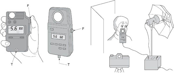
Figure 10.30 Hand-held flash meters – various brands. Several will also measure continuous light sources. All these meters are normally used with flash in incident light reading mode, at the subject facing the camera. T: Trigger cable socket. F: Firing button when in cabled mode
Disadvantages. A separate flash meter is really only practical where time and conditions permit you to take a trial flash reading before shooting – they are ideal in the studio, for example. Meters are also rather costly, and you have to remember that they do not automatically take into account camera filters or close-up focusing conditions which affect exposure in the camera.
Bounced flash
As discussed in Chapter 7, bouncing flash off a ceiling, wall or similar large surface area is a convenient way of softening lighting quality and improving evenness. However, you greatly reduce its intensity. When working by guide numbers the rule for a white bounce surface is: (1) halve the regular flash guide number, and (2) divide this new number by the total flash distance (i.e. flash to surface to subject) to discover your f-number. Flash meters, and dedicated flash, will take bounce light conditions into account in measuring exposure. It’s very important with a self-regulating flashgun that the sensor always faces the subject when the flash is directed upwards or sideways onto a bounce surface. This is usually taken care of in gun design, where the part containing the flash tube pivots and twists but the sensor remains fixed and forward-looking.
Figure 10.31 ‘Bouncing’ flash. The light sensor must continue to face the subject direct. Illuminate the ceiling above the camera, not subject – otherwise you risk shadowed eyes
Fill-in flash
Flash on the camera is a good way to lower subject contrast in side, top or back-lit ambient lighting situations. Of course, you cannot expect to fill-in whole buildings this way, but it is useful for portraits and average size room interiors. (Make sure, when shooting in colour, that flash and ambient lighting are the same colour temperature – in unalterable tungsten light conditions fit an orange 85B filter over the flash tube and shoot on tungsten film.) Diffuse and direct the flash from close to the lens to avoid casting additional shadows, and arrange to underexpose the flash aiming for a flash/existing-light ratio of about 1:4 (colour negatives).
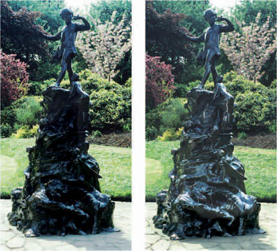
Figure 10.32 Fill-in flash. Near right: existing light only, no flash, 1/60 second at f/11. Far right: same exposure with the addition of flash from the camera set to one-quarter correct power for this subject distance. You need a powerful flashgun for fill-in flash outdoors beyond about 2.5 m, unless shooting early or late in the day
Advanced compacts and SLRs often offer a ‘fill-flash’ mode by which settings are made for the existing light but the camera’s built-in flash also fires, at quarter power.
Using more than one flash head
Like any other controlled lighting, there will be times when you want to use two or more flash sources from different positions, especially in the studio. With studio flash one arrangement (Figure 10.34) is to have separate units independently plugged into the electricity supply. The generator (or monobloc) powering one head is connected to the camera by synchronizing lead, or has a trigger which reacts to a battery-powered infra-red or radio pulse transmitter you mount in the camera’s hot shoe. The other pack or packs have a light sensitive ‘slave’ trigger plugged onto its synchronizing lead socket (or may be built-in, just needing to be switched on). This ensures that the second flash fires in instant response to the one linked to your camera.
These ‘slaved units’ can then be moved around in the studio with the freedom of tungsten lighting. Each can be turned down to half or quarter flash power; its modelling lamp dims pro rata, to show you the effect of having sources at different intensities. Another, cheaper arrangement is to have just one generator, plug several heads into it and place them in different positions. This means more leads to trip over, but only one link from the pack is needed to your camera. Remember, though, that power output from the pack is then split (for example, a 1500 watt-second unit gives 750 W/s each to two heads).
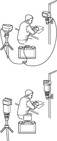
Figure 10.33 Using several heads at once. Top: two dedicated flashguns controlled from their ‘off the film’ metering camera by direct wiring. Bottom: set-up using self-regulating guns set to manual, the two off-camera being triggered by light slaves fitted below their heads. These respond to light from a small flash used on camera. (If frontal lighting is objectionable, IR triggering could be used instead)
The best way to measure exposure when using several heads is by flash meter. But if you use a guide number system instead, work according to the GN and distance of your main light flash source only, ignoring the others. A flash meter allows you to exactly measure the lighting ratio between main and fill-in units. First turn on the main flash source only, and fire it with the meter near your subject, facing the light. Secondly turn on the fill-light only instead, and read this facing its light. The difference between the two shows the light ratio. To avoid excessive contrast it’s best not to go beyond 4 stops difference for slide films, 5 for colour negatives.
With smaller battery-operated flashguns (Figure 10.33), you will need several complete units on stands wired or slaved to the camera. If guns are dedicated, you must have each one wired back to the camera to control their output. Then exposure measurement is simple – you just use the camera’s TTL meter for flash as normal.
If your flashguns are self-regulating but not dedicated types (or a mixture), it is least confusing to set them all to manual, wire them to the camera or a trigger for firing purposes, and then measure exposure by meter or just work from the guide number for your key source. Lack of modelling lamps is a big disadvantage with all battery flash when using several heads – you need experience and skill to predict where to place each one.
Speedy recycling
The faster your flash unit will recycle, the more rapidly you will be able to take pictures. This is important in most action and press photography, where any delay waiting for the flash to come up to power could lose you an unrepeatable image. And it is vital if you are shooting a sequence by motor drive.
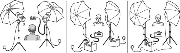
Figure 10.34 Some two flash-head set-ups in the studio. Below: A pair of monoheads. The one shown left here is triggered when its slave sensor (S) reacts to light from the unit sync wired to camera. Centre: Two more powerful generator type flash units, wired in the same way as the monoheads. Alternatively (far right) using two heads from a single generator. Maximum power light output is then split

Figure 10.35 Multiple flashes on one frame of film. A sequence of six flashes fired from a hand flashgun in a darkened room, from one side of the model. The camera shutter was locked open on B throughout. This flashgun was totally separate from the camera, and fired manually using the test button. Notice how the almost stationary trunk and legs build up exposure, while hands and fingers receive only one flash each. Set an f-number for halfway between these extremes
One way of working is to use a flash unit with a powerful generator turned down to a fraction of its full output. For example, one such unit allows you to select 1/100th of full power, and then recycles in 0.25 second, giving an extremely brief flash.
Regular studio flash units on full power take around 3 seconds to recycle, see table, Figure 10.29. They easily overheat if you try to make them fire and recycle in continuous sequence. Special models are therefore made with rapid-firing facility, but give a fraction of normal output.
• |
Exposure level alters image tonal and colour qualities; can be used to give emphasis, help interpretation. |
• |
The exposure needed depends on lighting, subject characteristics, film sensitivity and imaging conditions. It is given to the film through the combined effects of the intensity of the image light, and the time it acts on the emulsion. Exposure can be quoted in f-numbers and shutter speeds. |
• |
With negative films, avoid underexposure, which produces empty flat shadows. Severe overexposure gives grainier, less sharp results. Overexposure is worse than underexposure if you are shooting on reversal materials – slides and transparencies. Contrasty scenes allow you least exposure latitude. Where possible, intelligently bracket your exposures as insurance. |
The response to light by a film is published as a performance graph or ‘characteristic curve’. Where the graph flattens out (tones merge) at bottom and top represents under and overexposure zones. |
|
• |
A camera meter located behind the lens may read light off the film surface during time exposures, and for flash. Here it takes into account changes in focal length, close-up focusing and filters. Reading patterns range from centre-weighted averaging, to spot. |
• |
Camera settings may be made by the meter direct, working through a program, or you can choose from manual, aperture priority, and shutter priority modes. A fully programmed AE system gives good assurance of correctly exposed pictures – but not necessarily with the visual qualities you had in mind. |
• |
Your three main exposure decisions are the ISO rating you set for your film, the subject parts you measure (emphasis), and how exposure is distributed between shutter and aperture (movement and depth of field effects). |
• |
Substitute readings, and recomposing different areas of subject within the frame just while you measure exposure, often improves accuracy. |
• |
Since view cameras (and many rollfilm cameras) have no built-in meter, you will need to use a hand-held meter. Remember then to increase exposure for close-ups by (M + 1)2 and for any filter used. |
• |
General, overall readings are quick and convenient, but inaccurate when important areas are relatively small. Grey-card or incident-light readings measure exposure independently of the subject. Averaged brightness-range readings (ideally taken by spot metering) take longer but reveal scene contrast, too. |
• |
Flash exposure can be based on guide numbers (f-number × distance), measured by flash meter (most practical with studio units), or a sensor on a self-regulating flashgun, or the camera’s TTL system in circuit with a dedicated gun. |
• |
Electronic flash synchronization (X sync) suits between-lens shutters at all speeds. Focal plane shutters often impose a limiting top speed. |
• |
Self-regulating flash units, independent or dedicated, give shortened flash (and faster recycling) when there is a strong reflected-light measurement from the subject. |
• |
When you bounce flash halve its guide number at least; remember to measure the total light-path distance. Avoid coloured ceilings/walls. |
• |
With multi-unit set-ups, synchronize one studio flash to the camera and ‘slave’ the rest. Set self-regulating units to manual, have them wired or slaved to the camera. Check exposure (and lighting contrast) by flash meter, or work with the GN for the key light only. If you have dedicated flash units, wire them all to the camera, then use the TTL camera meter. |
• |
Fast-recycling flash is essential for rapid sequence work. Use a powerful gun at fractional setting, or a specially designed flash unit. |
• |
To fill in and reduce the contrast of ambient lighting, use on-camera flash set to fill-flash mode. If this is not offered make the camera settings correct for existing light and reduce the flash to 25 per cent correct output. |