Light: how images form
It was said earlier that you don’t have to understand physics to take good photographs. But understanding the practical principles behind photography and photographic equipment gives you a broader, more flexible approach to problem solving. It is also interesting. For example, the way light is manipulated to form images is not really very complicated – did you know it can be done with a hole in a card?
We start with the very foundation stone of photography, which is light. What precisely is light, and which of its basic features are helpful to know when you are illuminating a subject, using lenses and learning about colour? From light and colour we go on to discuss how surfaces and subjects look the way they do, and why light has to be bent with glass to create a usable image.
The lens is without doubt the most important part of any camera or enlarger. Starting with a simple magnifying-glass lens you can begin to see how photographic lenses form images. Later this will lead us on to other key components of camera equipment.
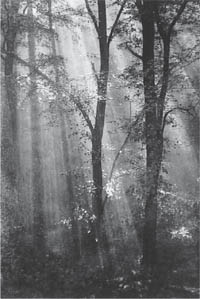
Figure 2.1 Light travels in straight lines, shown clearly in this wooded landscape by pictorialist Alexander Keighley (1917)
Light is fundamental to photography; it is even in its very name (‘photo’). And yet you are so familiar with light you almost take it for granted. Light is something your eyes are sensitive to, just as your ears relate to sound and your tongue to taste. It is the raw material of sight, communicating information about objects which are out of range of other senses. Using light you can show up some chosen aspects of a subject in front of the camera and suppress others. Light channels visual information via the camera lens onto photographic material, and enables you to enjoy the final result. At this very moment light reflected off this page carries the shape of words to your eyes, just as sound would form the link if we were talking. But what exactly is light?
Visible light is a stream of energy radiating away from the sun or similar radiant source. Its four important characteristics, all present at the same time, are:

Figure 2.2 Light travels on a straight line path but as if in waves, like the outward movement of ripples when a smooth water surface is disturbed
Light behaves as if it moves in waves, like ripples crossing the surface of water, Figure 2.2. Different wavelengths give our eyes the sensation of different colours. |
|
2 |
Light travels in a straight line (within a uniform substance). You can see this in light ‘beams’ and ‘shafts’ of sunlight, Figure 2.1, and the way that shadows fall. |
3 |
Light moves at great speed (300,000 kilometres or 186,000 miles per second through space). It moves less fast in air, and slightly slower still in denser substances such as water or glass. |
4 |
Light also behaves as if it consists of energy particles or ‘photons’. These bleach dyes, cause chemical changes in films and electronic response in digital camera sensors, etc. The more intense the light, the more photons it contains. |
What you recognize as light is just part of an enormous range of ‘electromagnetic radiations’. As shown left, this includes radio waves with wavelengths of hundreds of metres through to gamma and cosmic rays with wavelengths of less than ten thousand-millionths of a millimetre. Each band of electromagnetic radiation merges into the next, but has its own special characteristics. Some, such as radio, can be transmitted over vast distances. Others, such as X-rays, will penetrate thick steel, or destroy human tissue. Most of this radiation cannot be ‘seen’ directly by the human eye, however. Your eyes are only sensitive to a narrow band between wavelengths 400 nm and 700 nm approximately. (A nanometre or nm is one millionth of a millimetre.) This limited span of wavelengths is therefore known as the visible spectrum.

Figure 2.3 Some of the electromagnetic spectrum (left), and the small part of it forming the visible spectrum of light (enlarged, right). Mixed in roughly the proportions shown in colour here, the light appears ‘white’
When a relatively even mixture of all the visible wavelengths is produced by a light source the illumination looks ‘white’ and colourless. But if only some wavelengths are present the light appears coloured. For example, in Figure 2.3, wavelengths between about 400 nm and 450 nm are seen as dark purpley violet. This alters to blue if wavelengths are changed to 450–500 nm. Between 500 nm and 580 nm the light looks more blue-green, and from about 580 nm to 600 nm you see yellow. The yellow grows more orange if the light wavelengths become longer; at 650 nm it looks red, becoming darker as the limit of response is reached at 700 nm. So the colours of the spectrum – violet, blue, green, yellow and red – are really all present in different kinds of white light (sunlight, flash or studio lamps for example).

Figure 2.4 Most sources of light produce a mixture of wavelengths, differing in colour and expressed here in greatly simplified form
The human eye seems to contain three kinds of light receptors, responding to broad overlapping bands of blue, green and red wavelengths. When all three receptors are stimulated equally by something you see, you tend to experience it as white, or neutral grey. If there is a great imbalance of wavelengths – perhaps the light contains far more red (long) waves than blue (short) waves – stimulus is uneven. Light in this case may look orange tinted, just as happens every day around sunrise or sunset.
Try to remember the sequence of colours of the visible spectrum. It’s useful when you need to understand the response to colours of black and white films, or choose colour filters and darkroom safelights (see Chapter 12). Later you will see how the concept of three human visual receptors together responding to the full colour spectrum is adapted to make photographic colour films work too.
It seems odd that humans can biologically sense only a relatively tiny part of the vast electromagnetic spectrum. However, with most naturally occurring infra-red, ultra-violet, X-ray and gamma-ray wavelengths from space shielded from us by the Earth’s atmosphere, we have evolved without need of detection devices (or defences) for these kinds of radiation. Beings on another planet, with a totally different environment, might well have evolved with organs capable of sensing, say, radio waves but completely ‘blind’ to visible light as we know it.
Light travels in straight lines and in all directions from a light source. This means that if you have direct light from a comparatively ‘compact’ source such as the sun in a clear sky, a candle, bare light bulb or a small flash unit, this light is harsh. Objects throw contrasty, sharp-edged shadows. Figure 2.5 shows how having all the light issuing from one spot must give a sudden and complete shut-off of illumination at the shadow edge. But look what happens when you place tracing paper in the light beam (or block the direct light and reflect the remainder off a matt white wall, Figure 2.6). Tracing paper passes light but also diffuses it. The light passed through the paper scatters into new straight lines proceeding in all directions from every part of its large area surface. The object you were illuminating now casts a softer-edged, graduated shadow, and the larger and closer your diffusing material the less harsh and contrasty the shadow becomes. This is because light from a large area cannot be completely blocked out by the subject; most of the parts previously in shadow now receive at least some illumination. The same would happen with sunlight on an overcast day.

Figure 2.5 A compact, distant light source used direct makes objects cast a sharply defined shadow. A larger source – simply formed here by inserting a large sheet of tracing paper – gives a soft, graduated shadow. See also Figure 7.1

Figure 2.6 A lamp, sunlight or flashgun directed entirely onto a matt white surface such as a wall or large card will reflect to also give soft, diffused shadows
It’s very important in practical photography to recognize the difference between direct, harsh lighting and soft, diffused lighting. Shadow qualities greatly influence the way subjects and scenes look. Bear in mind this is not something you can alter in a photograph by some change of camera setting or later manipulation. Understanding and controlling lighting is discussed in detail in Chapter 7.
When light strikes a surface – maybe a building, or a landscape or face – what happens next depends upon the texture, tone and colour of the material, and the angle and colour content of the light itself.
Materials opaque to light
If the material is completely opaque to light – metal or brick for example – some light is reflected and some absorbed (turned into heat). The darker the material the smaller the proportion of light reflected. This is why a dark camera case left out in the sun gets warmer than a shiny metal one.
If the material is also coloured it reflects wavelengths of this colour and absorbs most of the other wavelengths present in the light. For example blue paint reflects blue, and absorbs red and green from white light. But if your light is already lacking some wavelengths this will alter subject appearance. To take an extreme case, when lit by deep red illumination, a rich blue will look and photograph black, see Figure 2.7. You need to know about such effects in order to use colour filters (Chapter 9).
Surface finish also greatly affects the way light is reflected. A matt surface such as an eggshell, drawing paper or dry skin scatters the light evenly. The angle from which light strikes it makes very little difference. However, if the surface is smooth and reflective it acts more like a mirror, and reflects almost all the light back in one direction. This is called specular reflection.
If your light strikes the shiny surface at right angles it is reflected backward along its original path. You get a patch of glare, for example, when flash-on-camera shots are taken flat on towards a polished glass window or gloss-painted wall. But if the light is angled it reflects off such surfaces at the same angle from which it arrived, Figure 2.7. So try to arrange your lighting direction or camera viewpoint to bounce glare light away when photographing a highly reflective surface. (If you are using built-in flash angle your camera viewpoint.)
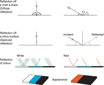
Figure 2.7 Light reflection. Top: Light reflected from a matt surface scatters relatively evenly. Centre: From a shiny surface light at 90° is returned direct. Oblique light directly reflects off at the same angle as it arrived (incident). Bottom: Coloured materials selectively reflect and absorb different wavelengths from white light. However, appearance changes when the viewing light is coloured
Materials transparent or translucent to light
Not every material is opaque to light, of course. Clear glass, plastic and water for example are transparent and transmit light directly, while tracing paper, cloud and ground glass diffuse the light they transmit and are called translucent. In both cases if the material is coloured it will pass more light of these wavelengths than other kinds. Deep red stained glass transmits red wavelengths but may be almost opaque to blue light, see Figure 2.8.
Since translucent materials scatter illumination they seem milky when held up to the light and look much more evenly illuminated than clearer materials, even when the light source is not lined up directly behind. Slide viewers work on this principle. The quality of the light is similar to that reflected from a white diffused surface.
Refraction
Interesting things happen when direct light passes obliquely from air into some other transparent material. As was said earlier, light travels slightly slower when passing through a denser medium. When light passes at an angle from air into glass, for example, its wavefront (remember the ripples on the water, Figure 2.2) becomes slowed unevenly. This is because one part reaches the denser material first and skews the light direction, like drawing a car at an angle into sand, Figure 2.9. A new straight-line path forms, slightly steeper into the glass (more perpendicular to its surface). The change of light path when light travels obliquely from one transparent medium into another is known as refraction.
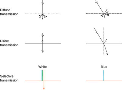
Figure 2.8 Light transmission: Top: Diffusely transmitting materials (milky plastic, ground glass) scatter light fairly evenly. Centre: Clear materials pass most of the light directly. Angled light is part reflected, mostly refracted. Bottom: Coloured materials pass only selected wavelengths from white light. When the viewing light is a colour different to the material, no light may get through
You can see refraction at work when you poke a straight stick into clear water; it looks bent at the water surface. Again, looking obliquely through a thick, half-closed window, parts of the view through the glass look offset relative to what can be seen direct. But most importantly because of refraction, lenses bend light and so form images, as we will come to shortly.
Remember that refraction only bends oblique light. Light which strikes the boundary of two transparent materials at right angles slows minutely but does not change direction. And most light reaching the boundary at a very low angle (very oblique) is reflected off the surface.
The whole picture
In practice then the range of objects around us appear the way they do because of the mixture of effects they have on light – diffuse and specular reflection, some absorption, often transmission and refraction too. An apple side-lit by direct sunlight for example reflects coloured wavelengths strongly from its illuminated half. Most of this is diffusely reflected, but part of its smooth skin reflects a bright specular highlight, just where the angle of the sun to the surface matches the angle from this point to your eye. The shape and relative darkness of the shadow to one side of the apple gives you further clues to its form. From experience your eyes and brain recognize all these subtle light ‘signals’ to signify solidity and roundness, without your actually having to touch the apple to find out. This is essentially what optical aspects of seeing and photographing objects are all about.

Figure 2.9 Refraction. Light slows when passing from air into glass. Wavefronts slow unevenly if light reaches the denser medium obliquely (left). The effect is like driving at an angle from the highway onto sand (right). Uneven drag causes change of direction. Light striking the boundary at right angles (centre) slows but does not alter direction
The closer your light source is to your subject the brighter it will be illuminated. Figure 2.11 shows that because light travels in straight lines a surface receives four times as much illumination (four times as many photons) from a compact light source as it would if the same-size surface were twice as far away. For example, if you are using a small flashgun or studio lamp to light a portrait, halving its distance from the subject gives you four times the light, so exposure can be quartered. The same applies to printing exposures when you alter enlarger height (Chapter 13, and in close-up situations, page 191).
In practice this ‘inverse square law’ (twice the light source distance one quarter the illumination) means that you must be especially careful when lighting a number of items at different distances in a small studio, using a harsh compact light source such as a spotlight. It may then be impossible to correctly expose items nearest and farthest from the light at any one exposure setting. A solution is to move the light source much further away, so the ratio of nearest to farthest distance becomes less (page 113), or change to a larger, diffused light source which will give you much less illumination ‘fall-off’ effect.

Figure 2.10 Imagine you are looking at this scene direct. Light would be communicating information about its different parts to you in a mixture of ways. The water jets transmit and refract light, glittering parts of the lake surface specularly reflect, while the grey stone diffusely reflects light. What little light from the sky alone reaches shadowed areas beneath the fountain is mostly absorbed by blackened stone
The same problem does not arise with direct sunlight outdoors. The sun is so vastly far away that any two places on earth – be they seashore or mountain peak – are almost equal in distance from the sun. Brightness variations in landscape photography may be created by local atmospheric conditions but not by the sun’s distance. If you are photographing indoors, however, using the sun’s light entering through a small window, the window itself acts like a compact light source. Intensity will then alter with distance in the same way as if you had a lamp this size in the same position.
Suppose you set up and illuminate a subject, and just face a piece of tracing paper (or film) towards it. You will not of course see any image on the sheet. The trouble is that every part of your subject is reflecting some light towards every part of the paper surface. This jumble of light simply illuminates it generally.
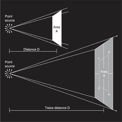
Figure 2.11 Direct light from a compact source (such as a small flash unit or studio lamp) illuminates your subject at quarter intensity when you double the lamp-to-subject distance. The same light spreads over four times the area. Known as ‘inverse square law’
One way to create order out of chaos is by restricting the light, adding between subject and paper a sheet of opaque material such as kitchen foil containing a pinhole. Since light travels in straight lines, those light rays from the top of the subject able to pass through the hole can only reach the bottom part of the paper. And light from lower parts of the subject only reaches the top of the paper (Figure 2.12). As a result your paper sheet shows a dim, rather fuzzy upside-down representation of the subject on the other side of the pinhole.
The best way to see a pinhole image is to be in a totally darkened room, with foil or black paper over the window facing a sunlit scene outside. Make a drawing-pin size hole in the foil and hold up tracing paper about 30 cm (12 in) in front of it to receive the image.
You can easily take colour photographs using a pinhole if your camera has a removable lens. See Project 1 at the end of the chapter. So the business of actually forming an image is not particularly complicated or technical.
Practical limitations to pinhole images
The trouble with a pinhole-formed image is that results are not good enough for most photography (see Figure 2.13). None of the image detail is ever quite sharp and clear, no matter where you position the tracing paper. This is because the narrow ‘bundle’ of light rays reflected from any one part of the subject through the pinhole forms a beam that is diverging (gradually getting wider). As Figure 2.12 showed, the best representation you can get of any one highlight or point of detail in the subject is a patch or disc of light. What should be details become many overlapping discs of light which give the image its fuzzy appearance.

Figure 2.12 Top: A sheet of paper just held up towards an illuminated subject receives a jumble of uncontrolled light rays, reflected from all its parts. Bottom: A pinhole in an opaque screen restricts rays from each part of the subject to a different area of the paper; a crude upsidedown image is formed

Figure 2.13 Pinhol versus lens. Pictures taken using a 35 mm SLR camera body fitted with (left) kitchen foil having a 0.25 mm diameter pinhole; (centre) a simple plastic magnifying glass ‘stopped down’ to f/8 with a hole in black paper; and (right) the camera’s standard 50 mm lens at f/11 (see Figure 3.6). Based on the camera’s TTL light readings, the pinhole needed 20 seconds, the magnifier 1/60 s and the lens 1/30 s exposure. When focused for the centre, the magnifier gives the poorest definition of all near picture edges. The pinhole gives slightly unsharp detail everywhere
Then again a pinhole-formed image is so dim. You can brighten it by enlarging the hole, but this makes image detail even less sharp and clear. (And if you make two holes you get two overlapping images, because light from any one part of the subject can then reach the paper in two places.)
Even if you accept a dimmer image and try to sharpen detail by using a still smaller hole, those discs of light can obviously never be smaller than the hole itself. And you quickly get to a point where further reduction actually makes results worse because of an optical effect known as diffraction, page 326. The smaller and rougher the hole the greater the percentage of light rays displaced by this effect, relative to others passing cleanly through the centre.
Using a lens instead
The best way to form a better image is to make the hole bigger rather than smaller, then bend the broad beam of light you produce so that it narrows (converges) instead of continuing to expand. This is done by using refraction through a piece of clear glass. Figure 2.9 showed how light passing obliquely from air into glass bends at the point of entry to become slightly more perpendicular to the surface. The opposite happens when light travels from glass into air, as air is less dense. So if you use a block of glass with sides which are non-parallel (Figure 2.14) the total effect of passing light through it is an overall change in direction.
In practice, a shaped piece of glass that is thicker in the centre than at its edges will accept quite a wide beam of diverging light and convert it into a converging beam. Mechanically it is easiest to create this required shape by grinding and polishing a circular disc of glass. So you have a circular glass converging lens.
When you make images using a lens instead of just a hole the upside-down picture on your tracing-paper screen appears much brighter, but details are only sharply resolved when the paper is at one ‘best’ distance from the lens. If you position it too close or too far away, the light rapidly broadens out (Figure 2.15) and points of detail turn into discs even larger than given by a pinhole. The result is a very unclear ‘out-of-focus’ effect. So a lens has to be focused precisely; the correct image position will depend on the light-bending power of the lens, and the distance between lens and subject.
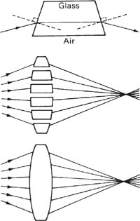
Figure 2.14 Lens evolution. Top: Using a non-parallel sided glass block, refraction at each air/glass surface (compare with centre of Figure 2.8) causes an overall change of direction. Think of a lens shape as a series of blocks which bend many light rays to a common point of focus
Focal length and image size
The light-bending power of a lens is shown by its focal length. As shown in Figure 2.17, the focal length of a simple lens is the distance between the lens and a sharply focused image of an object at infinity. (In practice this means something on the horizon.) Focal length takes into account the type of glass (its refractive index) and its shape.
A lens with a long focal length has relatively weak bending power – it needs a long distance to bend light rays to a point of focus. The stronger the power of the lens, the shorter its focal length. The picture detail is also smaller in size than the same subject imaged by a longer focal length lens.
Imaging closer subjects
The lens-to-image distance you need for sharp focus changes when your subject is nearer than infinity. The rule is: the closer your subject, the greater distance required between lens and image, see Figure 2.19. This is why you often see camera lenses move forwards when set for close distances, and for really close work you may have to fit an extension tube between body and lens (see page 90). Clearly there are problems when the scene you are photographing has a mixture of both distant and close detail, all of which you want in focus.

Figure 2.15 A converging lens bends diverging beams of light to a point of focus. However, if the lens-to-screen distance is incorrect, either too near or too far as shown right, images again consist of fuzzy ‘circles of confusion’. (This is why out-offocus highlights become discs – Figure 2.16)
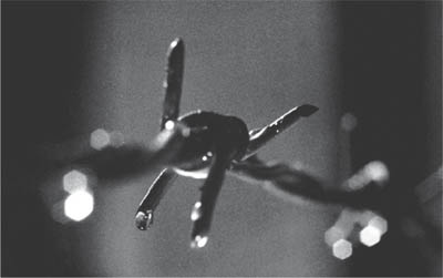
Figure 2.16 This image was made with a wide-diameter lens focused for one droplet on the barbed wire. Droplets closer (left) and further away (right) become unsharp patches of light at this focus setting. Notice how each patch takes on the shape of the lens diaphragm
Conjugate distances. Figure 2.20 shows the basic relationship between subject distances and image distances, in terms of lens focal length. These are known as linked or ‘conjugate’ distances. For example, light from a subject located somewhere between infinity and two focal lengths from your converging lens will come into focus somewhere in a zone between one and two focal lengths on the imaging side of the lens. It’s the kind of situation you meet in most general photography. Where the subject is precisely two focal lengths distant the sharp image is formed two focal lengths behind the lens, as well as being exactly the same size as the subject. Magnification (height of subject divided into the height of its image) is then said to be 1. This is a typical situation for close-up and ‘actual size’ photography.

Figure 2.17 Focal length. In the case of a simple lens, focal length is the distance between the lens and the position of a sharp image of an object at infinity
When your subject is closer than two focal lengths, the image is formed beyond two focal lengths behind the lens, and magnification is more than 1. In other words, the image shows the subject enlarged. This is the situation when a lens is used for projecting slides or making enlargements.
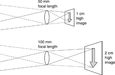
Figure 2.18 Focal length and image size. The longer the focal length the larger the image. This is why cameras taking large format pictures need longer focal length lenses to include the same amount of your subject

Figure 2.19 The closer the subject to a lens, the greater the distance it needs to bring the light into sharp focus. Light rays from a distant subject point are more parallel, so the same lens bending power brings them to focus nearer to the lens
The nearer your subject comes to being one focal length from the lens, the bigger and further away its sharp image becomes. When it is exactly one focal length away no image forms at all; light passes out of the lens as parallel rays. (This is the reverse of imaging a subject located at infinity, Figure 2.17.)
Check out all these imaging zones for yourself, using a converginglens reading glass and piece of tracing paper. It is always helpful to know (at least roughly) where and what size to expect a sharp image, especially when you are shooting close-ups, or printing unusual size enlargements. Ways of calculating detailed sizes and distances are shown on page 305.

Figure 2.20 Conjugate distances. The positions where subjects at different distances from a lens are sharply imaged
Summary. Light: how images form
• |
Light travels in straight lines, as if in wave motion. Wavelengths are measured in nanometers. Light forms a tiny part of a much wider range of electromagnetic radiation. It transmits energy in the form of ‘photons’. |
• |
Your eyes recognize wavelengths between 400 nm and 700 nm as progressively violet, blue, green, yellow, red – the visible spectrum. All colours if present together are seen as ‘white’ light. |
Subjects illuminated by a relatively compact direct light source cast harsh, hard-edged shadows. Light from a large-area source (including hard light diffused) gives softer, graduated shadows. |
|
• |
Light striking an opaque material is absorbed and/or reflected. |
• |
Smooth, shiny surfaces give you specular reflection – direct light is mostly reflected all one way. Oblique illumination bounces off such a surface at an angle matching the light received. Matt surfaces scatter reflected light and are much less directional. |
• |
Transparent materials directly transmit light; translucent materials diffuse light. Light passing obliquely from one transparent material to another of different density is refracted (bent) more perpendicular to the surface in the denser medium. |
• |
Coloured materials absorb and reflect or transmit light selectively according to wavelength. Appearance varies with the colour of the light source illuminating them. |
• |
The amount of illumination (photons) received by a surface area from a direct, compact light source is quartered each time its distance from the light source is doubled. |
• |
Because light travels in straight lines a pinhole in an opaque material forms a crude upside-down image of an illuminated subject. |
• |
A converging lens gives you a brighter, sharper image than a pinhole, by bending a wide beam of diverging light from your subject so that it converges to a point of focus. The position of sharp focus depends on the refracting power of the lens, and subject distance. |
• |
Lens power is shown by focal length, in simple optics the distance between the lens and a sharp image of an object at infinity. The longer the focal length the larger the image. |
• |
Close subjects come to focus farther from the lens than distant subjects. A subject two focal lengths in front of the lens is imaged same-size two focal lengths behind the lens. Magnification is image height divided by subject height. |
1 |
Take pinhole colour slides. Remove the lens from a single-lens-reflex 35 mm camera and tape kitchen foil in its place (it is easiest to tape it across an extension ring which you then simply attach or detach from the body). Pierce the foil with a needle to give a hole about 0.3 mm diameter, free of bent or ragged edges. You should just be able to make out the image of a bright scene through your camera viewfinder. Set your internal exposure meter to manual mode. If the image is too dim to get readings, set the camera’s ISO scale to its highest rating or the exposure-compensation dial to the most extreme minus setting. Then multiply the exposure time shown either by the set ISO divided by the actual ISO, or the equivalent effect of the compensation setting. |
2 |
Take pictures using a magnifying (reading) glass in place of your regular SLR camera lens. Fit a collar of black paper around the rim of the glass to prevent direct light entering the camera. Try some shots adding black paper with a hole in it over the lens to reduce its diameter by half. Compare the results, and also against results of Project 1. |
Practise forming images on tracing paper with a magnifying glass, or the lens detached from your camera. Work in a darkened room and use a lit hand torch as your subject. Check out image size as well as position when the subject is in the various distance zones shown in Figure 2.20. |