
In the previous chapter, we used a debugging option that allowed our augmented reality app to display the world origin, which showed the x-, y-, and z-axes based on the iOS device’s current location. Based on this world origin, we can place virtual objects in the augmented reality view by defining its x, y, and z coordinates.
ARKit offers another debugging option, called feature points. Like the world origin, you’ll only use feature points to debug your app. When it’s time to ship your app, you’ll remove both the world origin and feature points from appearing.
This line tells Xcode to display both the world origin (.showWorldOrigin) and feature points (.showFeaturePoints).
In our previous app, we could create yellow spheres along with the world origin, and then reset tracking to make the world origin appear in the new current location of the iOS device. Generally when you reset tracking and delete any existing virtual objects (such as our yellow spheres), you’ll also want to remove anchors.
Anchors define the position of virtual objects in an augmented reality view. Our previous app just removed the virtual objects from view, but once we delete the yellow sphere, we also don’t need to know the sphere’s previous position or anchor anymore, so we should delete that as well.
This code resets the world origin (.resetTracking) and removes any invisible anchors defining the position of virtual objects (.removeExistingAnchors).
Click the Run button or choose Product ➤ Run with an iOS device connected to your Macintosh through its USB cable. When the app runs, you’ll see feature points displayed as yellow dots that show you when ARKit detects surfaces of objects in the real world. The more dots that appear, the better ARKit detects that surface.
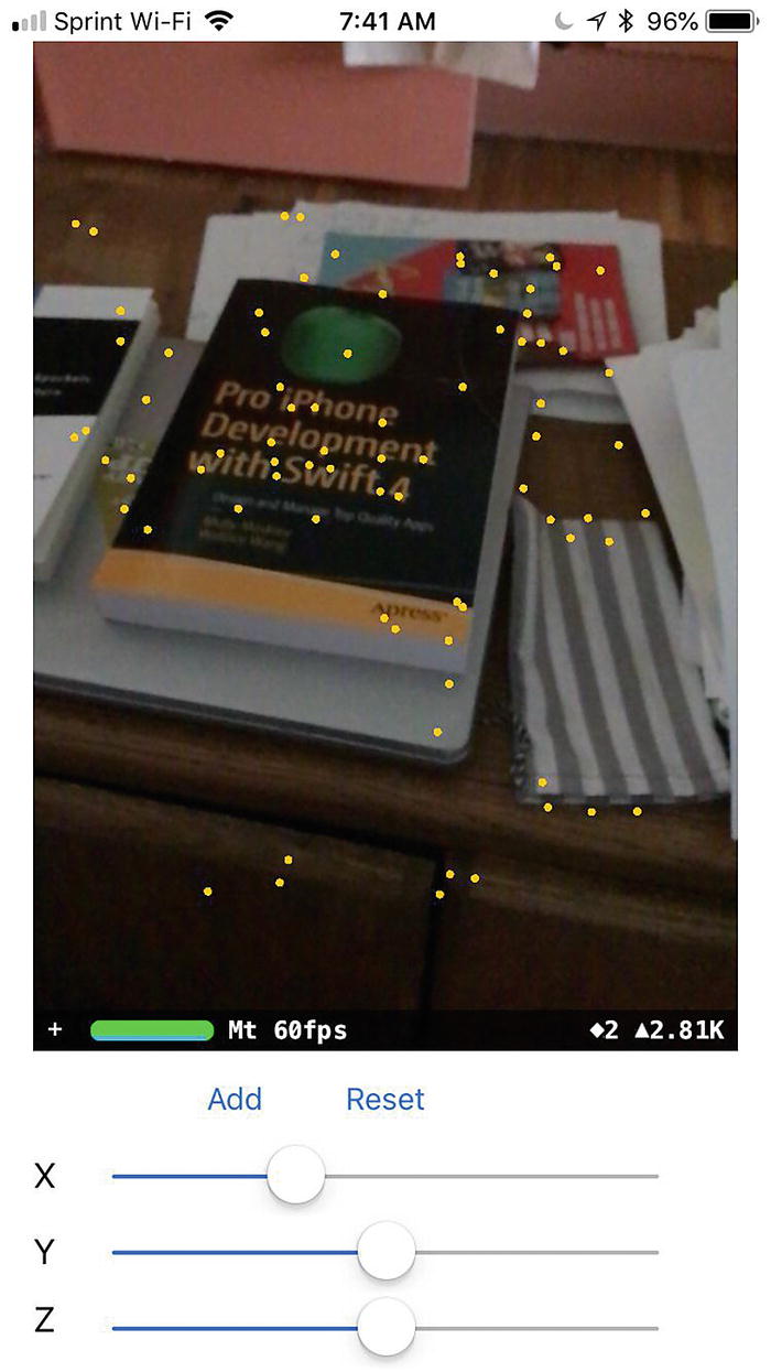
Feature points show how ARKit recognizes surfaces in the real world
Click the Stop button or choose Product ➤ Stop to stop your app from running.
Displaying Different Geometric Shapes
Geometric shapes are the simplest types of virtual objects you can display in an augmented reality view. In the previous chapter, we created a sphere, but SceneKit actually offers several different types of geometric shapes to use. Each geometric shape may require you to specify different dimensions.
SCNFloor
SCNBox
SCNCapsule
SCNCone
SCNCylinder
SCNPlane
SCNPyramid
SCNTorus
SCNTube
All of these geometric shapes work alike in that you can define a color for their surface, as UIColor.blue or UIColor.red. By combining multiple geometric shapes, you can create simple virtual objects that appear within an augmented reality view.
To create a box, we need to define its height, width, and length, as shown in Figure 4-2. In addition, you can also define the edges of the box to make them sharp or round. To modify the corner of a box, you need to define its chamfer radius. A radius of zero creates a sharp edge while non-zero values create a rounded edge. The higher the value, the rounder the edge.
- 1.
Click on the ViewController.swift file of the current app that displays three sliders for defining the x, y, and z coordinates of a shape.
- 2.Move the cursor to the front of the node.geometry = SCNSphere(radius: 0.05) line and type //, which turns the line into a comment. That means the text appears visible but won’t affect your app in any way. As soon as you type // in front of the line, Xcode dims the code like this:// node.geometry = SCNSphere(radius: 0.05)
- 3.Type underneath this line the following code:node.geometry = SCNBox(width: 0.1, height: 0.2, length: 0.1, chamferRadius: 0)
- 4.Replace where text "sphere" with "shape" in two places like this:if node.name == "shape" {node.removeFromParentNode()}andnode.name = "shape"
- 5.
Connect an iOS device to your Macintosh through its USB cable.
- 6.
Click the Run button or choose Product ➤ Run.
- 7.
Adjust the x, y, and z sliders to change the location of the shape.
- 8.
Tap the Add button to see a yellow box appear in the augmented reality view, as shown in Figure 4-2.
Displaying a box in augmented reality
- 9.
Click the Stop button or choose Product ➤ Stop.

Displaying a box with rounded edges
node.geometry = SCNSphere(radius: 0.05)
node.geometry = SCNBox(width: 0.1, height: 0.2, length: 0.1, chamferRadius: 0.05)
node.geometry = SCNTorus(ringRadius: 0.2, pipeRadius: 0.05)
node.geometry = SCNTube(innerRadius: 0.08, outerRadius: 0.1, height: 0.2)
node.geometry = SCNCapsule(capRadius: 0.06, height: 0.4)
node.geometry = SCNCylinder(radius: 0.04, height: 0.3)
node.geometry = SCNCone(topRadius: 0, bottomRadius: 0.05, height: 0.2)
node.geometry = SCNPyramid(width: 0.2, height: 0.4, length: 0.2)
node.geometry = SCNPlane(width: 0.2, height: 0.3)

Displaying a torus
Displaying Text
Besides displaying geometric shapes in augmented reality, you can also display text. When displaying text you can define a string to display along with the text’s font, size, and color.
- 1.
Modify the World Tracking project or create a new project identical to the World Tracking project except give it a different name such as Node Placement Text.
- 2.Modify the ViewController.swift file so the code looks like this:import UIKitimport SceneKitimport ARKitclass ViewController: UIViewController, ARSCNViewDelegate {@IBOutlet var sceneView: ARSCNView!@IBOutlet var Xslider: UISlider!@IBOutlet var Yslider: UISlider!@IBOutlet var Zslider: UISlider!let configuration = ARWorldTrackingConfiguration()override func viewDidLoad() {super.viewDidLoad()// Do any additional setup after loading the view, typically from a nib.sceneView.delegate = selfsceneView.showsStatistics = truesceneView.debugOptions = [ARSCNDebugOptions.showWorldOrigin, ARSCNDebugOptions.showFeaturePoints]}override func viewWillAppear(_ animated: Bool) {super.viewWillAppear(animated)sceneView.session.run(configuration)}@IBAction func addButton(_ sender: UIButton) {showShape()}@IBAction func resetButton(_ sender: UIButton) {sceneView.session.pause()sceneView.scene.rootNode.enumerateChildNodes { (node, _) inif node.name == "shape" {node.removeFromParentNode()}}sceneView.session.run(configuration, options: [.resetTracking, .removeExistingAnchors])}func showShape() {let text = SCNText(string: "Hello", extrusionDepth: 1)let material = SCNMaterial()material.diffuse.contents = UIColor.orangetext.materials = [material]let node = SCNNode()node.position = SCNVector3(Xslider.value, Yslider.value, Zslider.value)node.scale = SCNVector3(0.01, 0.01, 0.01)node.geometry = textnode.name = "shape"sceneView.scene.rootNode.addChildNode(node)}}
- 3.
Connect an iOS device to your Macintosh through its USB cable.
- 4.
Click the Run button or choose Product ➤ Run.
- 5.
Tap the Add button. Orange text appears where you defined the x, y, and z coordinates, as shown in Figure 4-5.
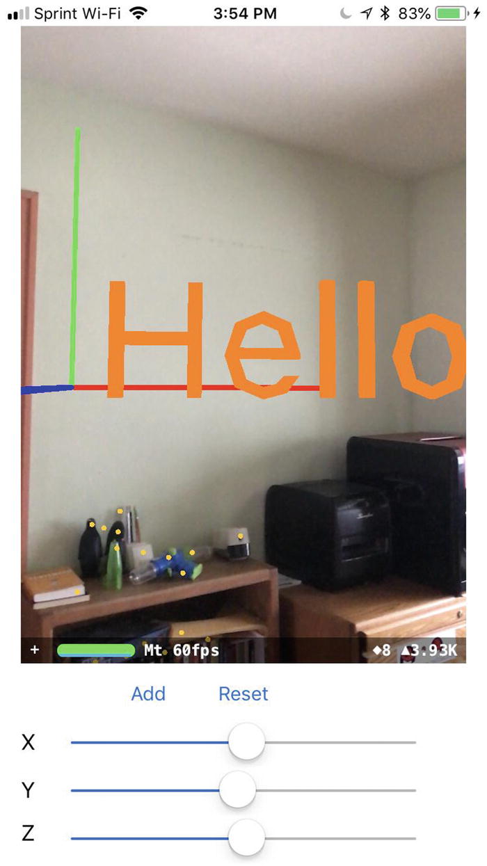
Displaying text in augmented reality
- 6.
Click the Stop button or choose Product ➤ Stop.
Try experimenting with different text and extrusion depth along with different colors.
Adding Textures to Shapes
In the examples we’ve created so far, we’ve simply used solid colors to color the geometric shapes we’ve added to our augmented reality view. However, you can apply graphic images to the surface of geometric shapes. This can create interesting visual effects such as showing shapes as planets or boxes that looks like they’re made out of bricks.

Finding texture images on the Internet
- 1.
Modify the current Xcode project you used to display text or create a new project that allows the use of the camera to display an augmented reality view. (This should be the Xcode project you created earlier for this chapter.)
- 2.
Drag the texture image to the navigator pane of your Xcode project. A window appears, displaying different options for adding a file, as shown in Figure 4-7.
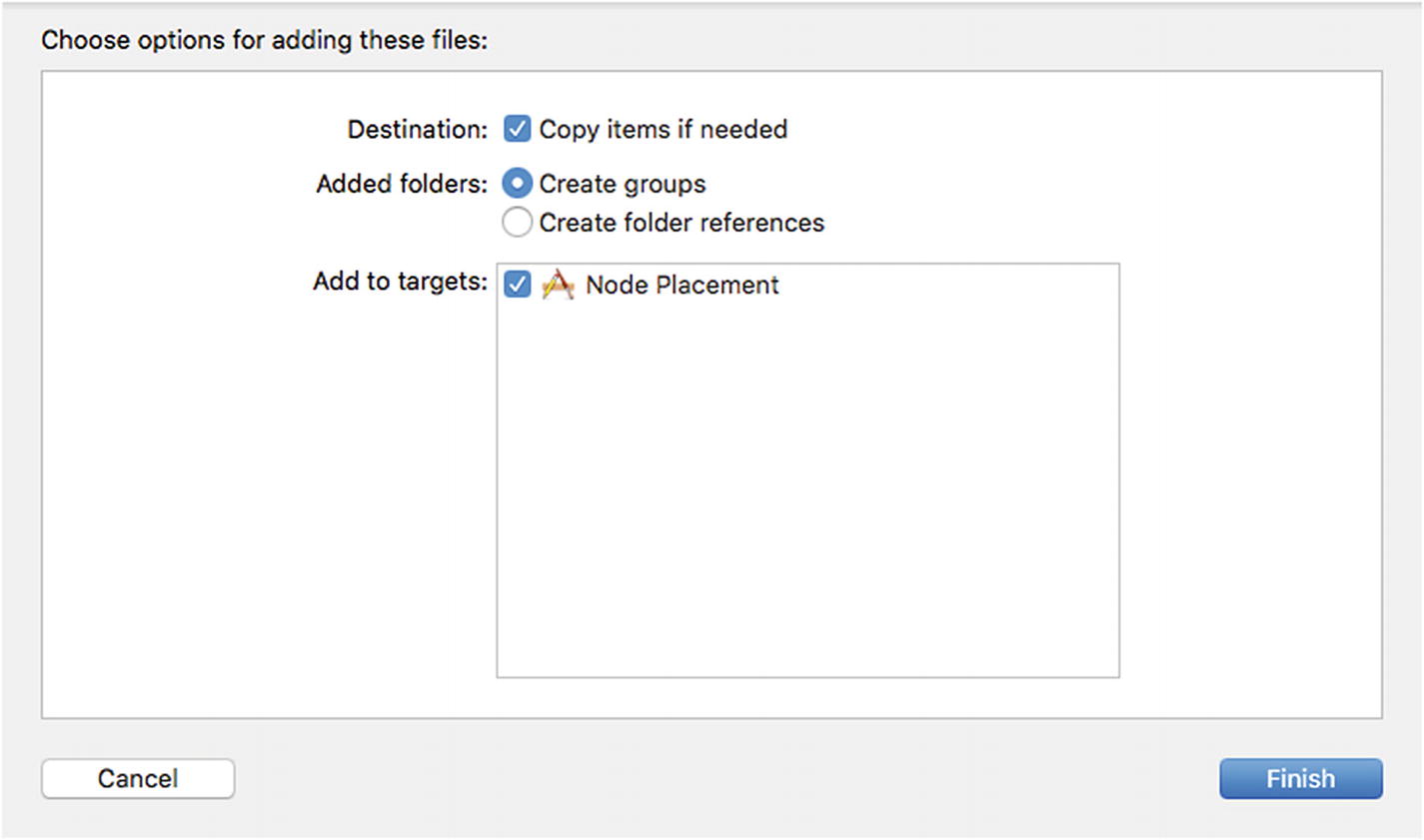
Adding a file to an Xcode project
- 3.
Make sure the Copy Items if Needed check box is selected and then click the Finish button.
- 4.
Click on the stexture file you just added in the Navigator pane. Xcode displays the contents of that texture image, as shown in Figure 4-8.
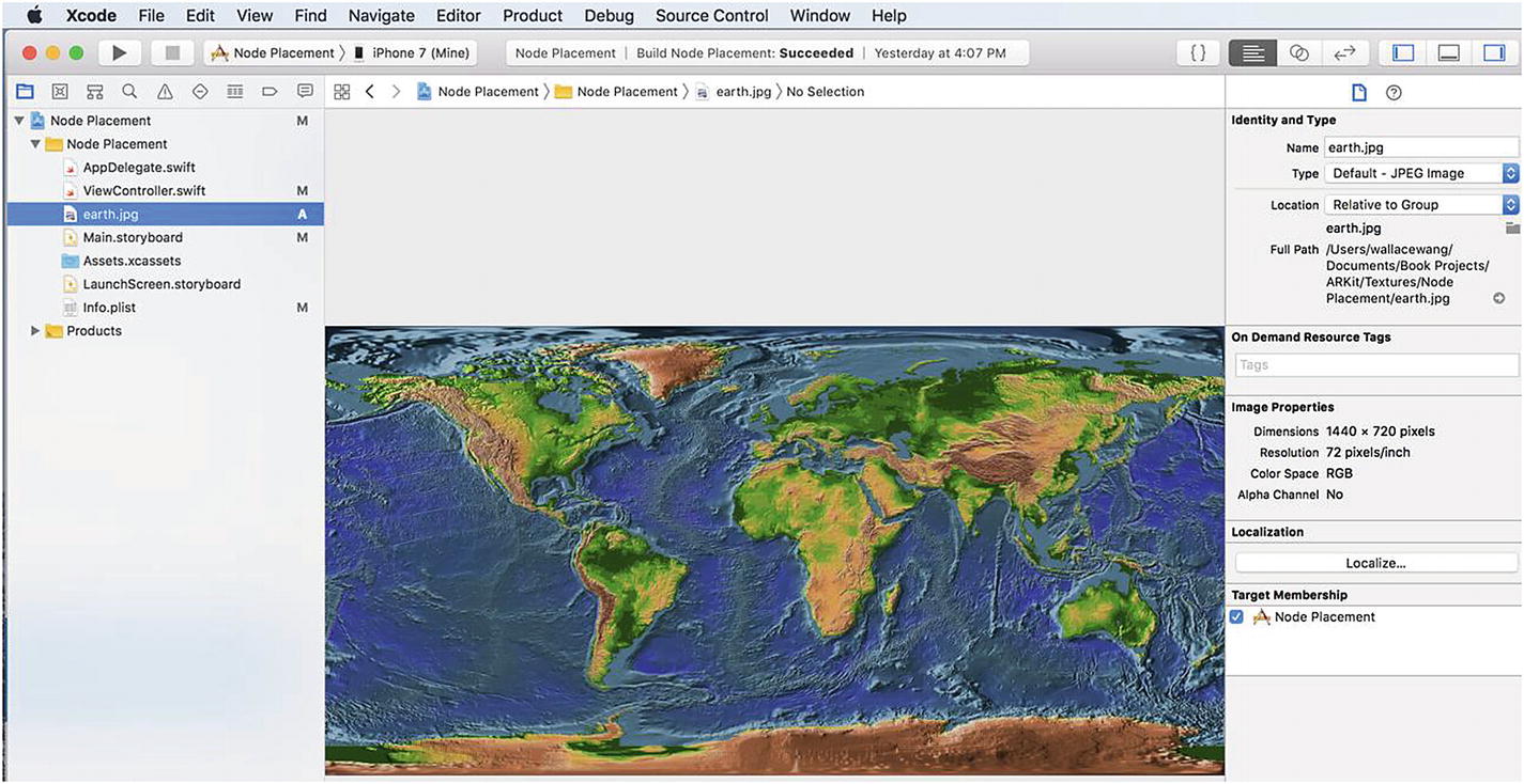
Selecting a texture file displays its contents in Xcode
In this example, the texture image is called earth.jpg but you’ll need to change this to the name of your specific image file, including the file extension such as .jpg.
- 1.
Click on the ViewController.swift file in the Navigator pane.
- 2.Edit the contents of the ViewController.swift file so it looks like the following:import UIKitimport SceneKitimport ARKitclass ViewController: UIViewController, ARSCNViewDelegate {@IBOutlet var sceneView: ARSCNView!@IBOutlet var Xslider: UISlider!@IBOutlet var Yslider: UISlider!@IBOutlet var Zslider: UISlider!let configuration = ARWorldTrackingConfiguration()override func viewDidLoad() {super.viewDidLoad()// Do any additional setup after loading the view, typically from a nib.sceneView.delegate = selfsceneView.showsStatistics = truesceneView.debugOptions = [ARSCNDebugOptions.showWorldOrigin, ARSCNDebugOptions.showFeaturePoints]}override func viewWillAppear(_ animated: Bool) {super.viewWillAppear(animated)sceneView.session.run(configuration)}@IBAction func addButton(_ sender: UIButton) {showShape()}@IBAction func resetButton(_ sender: UIButton) {sceneView.session.pause()sceneView.scene.rootNode.enumerateChildNodes { (node, _) inif node.name == "shape" {node.removeFromParentNode()}}sceneView.session.run(configuration, options: [.resetTracking, .removeExistingAnchors])}func showShape() {let sphere = SCNSphere(radius: 0.05)let material = SCNMaterial()material.diffuse.contents = UIImage(named: "earth.jpg")sphere.materials = [material]let node = SCNNode()node.geometry = spherenode.position = SCNVector3(Xslider.value,Yslider.value,Zslider.value)node.name = "shape"sceneView.scene.rootNode.addChildNode(node)}}
- 3.
Connect an iOS device to your Macintosh with its USB cable.
- 4.
Click the Run button or chose Product ➤ Run.
- 5.
Use the sliders to define an x, y, and z coordinate for your sphere and tap the Add button. The sphere appears covered in the texture file you specified, as shown in Figure 4-9.

Displaying a texture file over a geometric shape
- 6.
Click the Stop button or choose Product ➤ Stop in Xcode.

You can display different geometric shapes and textures
Changing the Transparency of Shapes
- 1.
Use the Xcode project that displayed a texture over a geometric shape.
- 2.
Click on the ViewController.swift file in the Navigator pane.
- 3.Add the following line under the line that defines the texture of a geometric shape, such as:material.diffuse.contents = UIImage(named: "wood.jpg")material.transparency = 0.6Remember to replace "wood.jpg" with the filename and extension of the texture file you’re using. The entire ViewController.swift file should look like this:import UIKitimport SceneKitimport ARKitclass ViewController: UIViewController, ARSCNViewDelegate {@IBOutlet var sceneView: ARSCNView!@IBOutlet var Xslider: UISlider!@IBOutlet var Yslider: UISlider!@IBOutlet var Zslider: UISlider!let configuration = ARWorldTrackingConfiguration()override func viewDidLoad() {super.viewDidLoad()// Do any additional setup after loading the view, typically from a nib.sceneView.delegate = selfsceneView.showsStatistics = truesceneView.debugOptions = [ARSCNDebugOptions.showWorldOrigin, ARSCNDebugOptions.showFeaturePoints]}override func viewWillAppear(_ animated: Bool) {super.viewWillAppear(animated)sceneView.session.run(configuration)}@IBAction func addButton(_ sender: UIButton) {showShape()}@IBAction func resetButton(_ sender: UIButton) {sceneView.session.pause()sceneView.scene.rootNode.enumerateChildNodes { (node, _) inif node.name == "shape" {node.removeFromParentNode()}}sceneView.session.run(configuration, options: [.resetTracking, .removeExistingAnchors])}func showShape() {//let sphere = SCNSphere(radius: 0.05)let pyramid = SCNPyramid(width: 0.04, height: 0.03, length: 0.04)let material = SCNMaterial()material.diffuse.contents = UIImage(named: "wood.jpg")material.transparency = 0.6//material.diffuse.contents = UIImage(named: "earth.jpg")//sphere.materials = [material]pyramid.materials = [material]let node = SCNNode()node.geometry = pyramid// spherenode.position = SCNVector3(Xslider.value,Yslider.value,Zslider.value)node.name = "shape"sceneView.scene.rootNode.addChildNode(node)}}
- 4.
Connect an iOS device to your Macintosh with its USB cable.
- 5.
Click the Run button or choose Product ➤ Run.
- 6.
Modify the sliders to define the x, y, and z coordinates of the shape.
- 7.
Tap the Add button. Notice that the shape now appears transparent, as shown in Figure 4-11.

Displaying a geometric shape and texture as transparent
- 8.
Click the Stop button or choose Product ➤ Stop.
Drawing Shapes
By offering different geometric shapes you can customize, ARKit makes it easy to add virtual objects to any augmented reality view. However, what if you want to create a shape that doesn’t fit within the confines of a common geometric shape like a box or a sphere? The simplest solution is to draw your own shape.
This plane.addLine command tells Xcode to start drawing at the beginning x and y coordinates defined by the plane.move command. Then the plane.addLine command draws a line 0 that points along the x-axis and 0.1 distance that points along the y-axis.
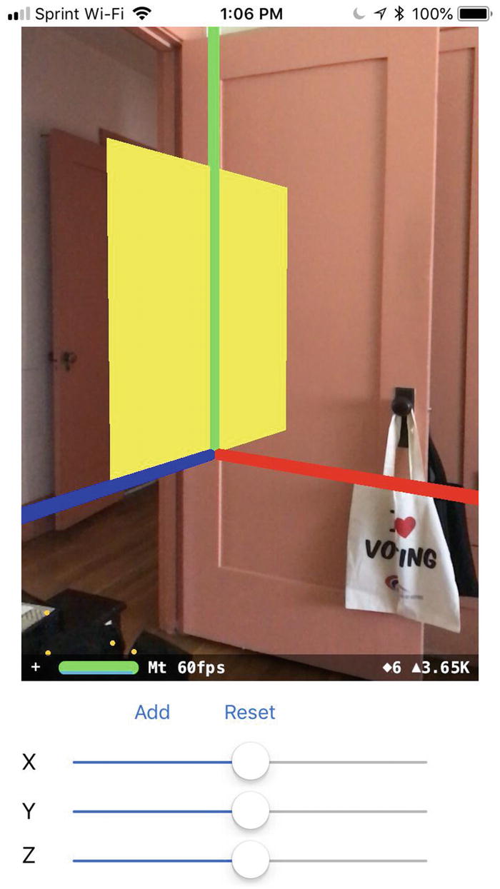
Displaying a plane defined by its distance along the x-, y-, and z-axes
- 1.
Use the Xcode project that displayed a texture over a geometric shape.
- 2.
Click on the ViewController.swift file in the Navigator pane.
- 3.Edit the showShape function so the entire ViewController.swift file looks like this:import UIKitimport SceneKitimport ARKitclass ViewController: UIViewController, ARSCNViewDelegate {@IBOutlet var sceneView: ARSCNView!@IBOutlet var Xslider: UISlider!@IBOutlet var Yslider: UISlider!@IBOutlet var Zslider: UISlider!let configuration = ARWorldTrackingConfiguration()override func viewDidLoad() {super.viewDidLoad()// Do any additional setup after loading the view, typically from a nib.sceneView.delegate = selfsceneView.showsStatistics = truesceneView.debugOptions = [ARSCNDebugOptions.showWorldOrigin, ARSCNDebugOptions.showFeaturePoints]}override func viewWillAppear(_ animated: Bool) {super.viewWillAppear(animated)sceneView.session.run(configuration)}@IBAction func addButton(_ sender: UIButton) {showShape()}@IBAction func resetButton(_ sender: UIButton) {sceneView.session.pause()sceneView.scene.rootNode.enumerateChildNodes { (node, _) inif node.name == "shape" {node.removeFromParentNode()}}sceneView.session.run(configuration, options: [.resetTracking, .removeExistingAnchors])}func showShape() {let plane = UIBezierPath()plane.move(to: CGPoint(x: 0, y: 0))plane.addLine(to: CGPoint(x: 0.1, y: 0.1))plane.addLine(to: CGPoint(x: 0.1, y: -0.03))let customShape = SCNShape(path: plane, extrusionDepth: 0.1)let node = SCNNode()node.geometry = customShapenode.geometry?.firstMaterial?.diffuse.contents = UIColor.yellownode.position = SCNVector3(Xslider.value,Yslider.value,Zslider.value)node.name = "shape"sceneView.scene.rootNode.addChildNode(node)}}
- 4.
Connect an iOS device to your Macintosh through its USB cable.
- 5.
Click the Run button or choose Product ➤ Run.
- 6.
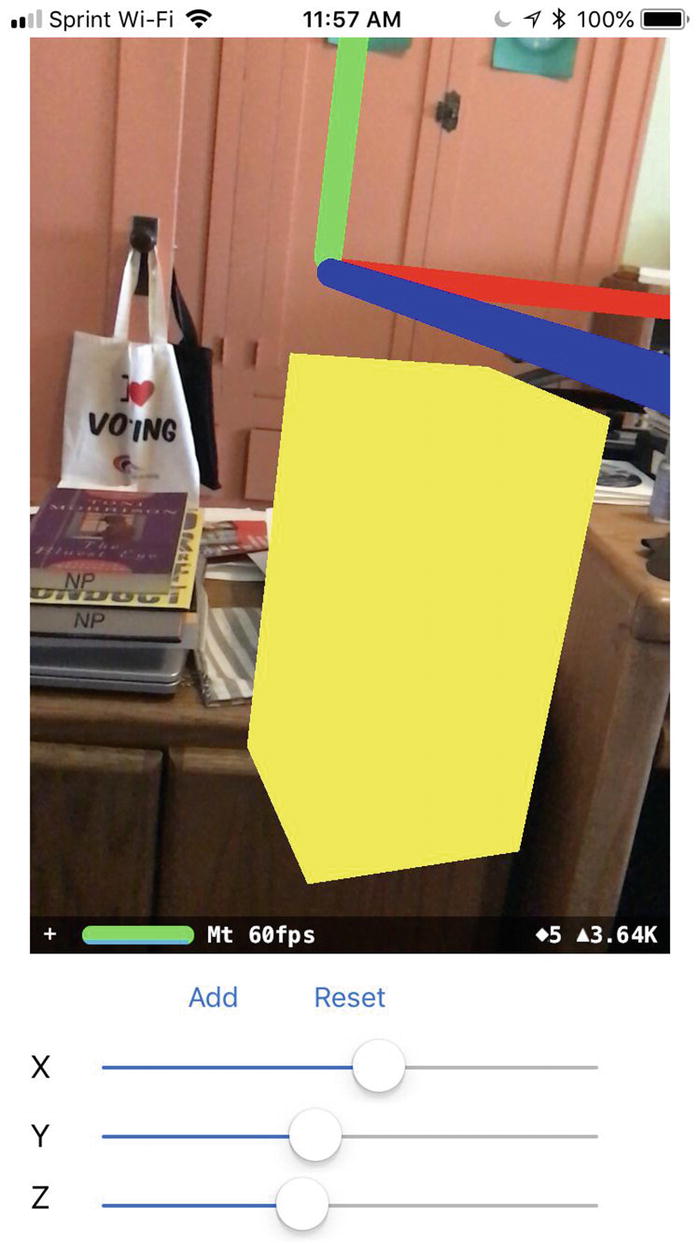
Tap the Add button when the app runs. A yellow wedge appears, as shown in Figure 4-13.
- 7.
Click the Stop button or choose Product ➤ Stop.
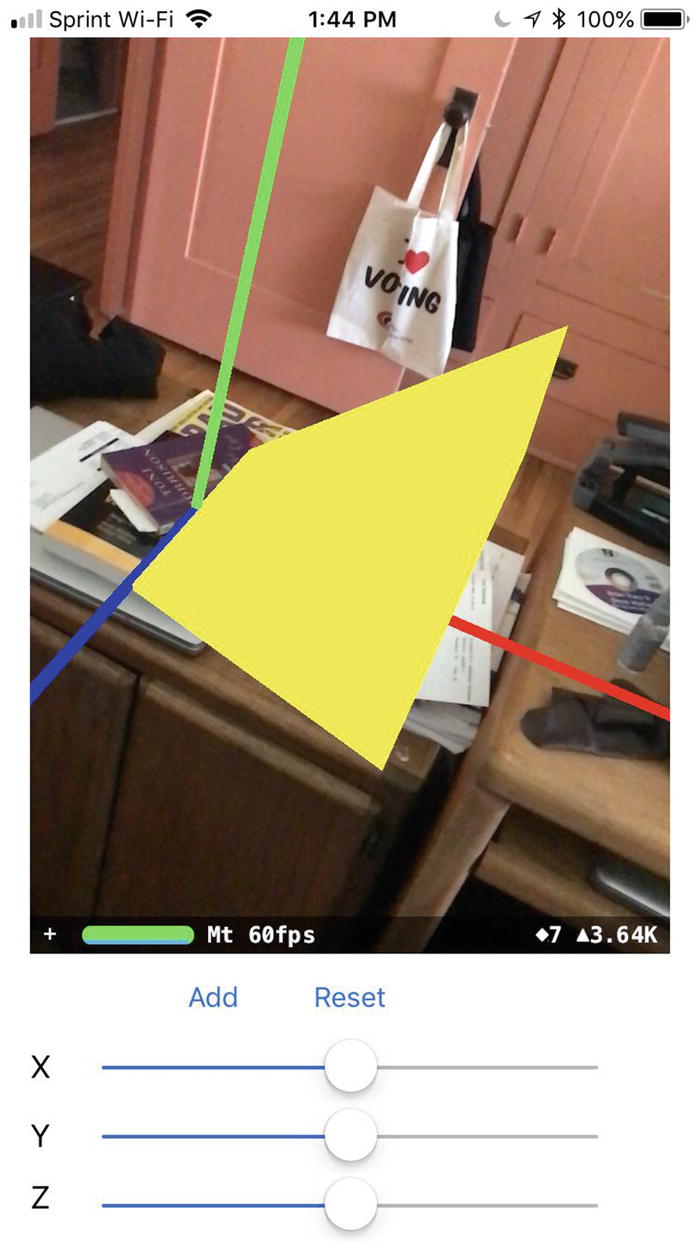
Two addLine commands help define a wedge shape
By using as many addLine commands as you wish, you can define your own custom three-dimensional shapes that can’t be created by common geometric shapes like spheres, boxes, or cones.
Summary
Besides displaying 3D images, ARKit can also display geometric shapes in an augmented reality view. Some common geometric shapes include boxes, spheres, planes, and cylinders. By specifying dimensions and positions, you can make a geometric shape appear anywhere.
After defining the dimensions of a geometric shape, you can modify its appearance by choosing different colors for its surface. For more variety, you can also apply different texture images to cover the surfaces of any geometric shapes you create.
In case no geometric shape matches what you need, you can draw individual lines to create your own virtual objects to display in an augmented reality view. By drawing lines and combining multiple geometric shapes, you can create custom shapes limited only by your imagination.
Colors and textures can give your geometric shapes a distinctive appearance. In the next chapter, we learn other ways to alter the appearance of virtual objects using different lighting sources.