Above all else, the Kinect is an overpriced camera (half kidding), and it is imperative that we learn how to work with its image data before we can understand how other features like gestures work. For most amateur applications, you will probably want to give the user some visual feedback anyway. In this chapter, we will explore the peculiarities of working with the various image data sources.
ColorFrameSource: Color Image Data
In Chapter 2, we very briefly mentioned ColorFrameSource as one of the many Kinect Data Sources. We went over the general pattern for recovering data from ColorFrameSource, but we will now proceed to fill in the blanks. We will build an application to stream the Kinect’s video feed from scratch. The code is similar to the samples in SDK Browser v2.0, so do not hesitate to follow along with them if you prefer.
ColorFrameSource in WPF
Start off by creating a C# WPF project in Visual Studio. Next, add your Microsoft.Kinect reference. This time, we will be including two additional references, System.Windows.Media and System.Windows.Media.Imaging, which will aid us in turning the Kinect color data into proper images for display and saving.
Tip
If you do not recall how to start a new project in Visual Studio, or how to add references, revisit Chapter 1. You can use the Ctrl-Shift-N key combination to quickly start a new project. You do not need to add the System.Windows.Media and System.Windows.Media.Imaging namespaces through NuGet or the Visual Studio References manager, as they are a part of WPF’s core assemblies, which are by default included by Visual Studio. Simply mention them in the code with the other using statements. Many project templates in Visual Studio will include them by default.
Right underneath our class declaration , we will initialize a few variables, as seen in Listing 3-1.
Listing 3-1. MainWindow.xaml.cs Variable Initialization for Color Data
public partial class MainWindow : Window{private KinectSensor kinect = null;private ColorFrameReader colorFrameReader = null;private WriteableBitmap colorBitmap = null;...
In Listing 3-1, in addition to our KinectSensor object, we are declaring a ColorFrameReader and a WriteableBitmap. As we discussed in Chapter 2, the ColorFrameReader will be reading frames from the Kinect. WriteableBitmap is a WPF object that allows us to modify a set of pixels dynamically. Instead of creating and destroying a new bitmap for every frame of data we receive from the Kinect through use of a BitmapImage, our WriteableBitmap will allow us to flexibly update the relevant pixels in our image without having to reallocate memory each time around.
In Listing 3-2, we bootstrap our Kinect and its color Data Source within our class constructor.
Listing 3-2. MainWindow.xaml.cs Data Source Bootstrapping and Variable Assignment for Color Data
public MainWindow(){this.kinect = KinectSensor.GetDefault();this.colorFrameReader = this.kinect.ColorFrameSource.OpenReader();this.colorFrameReader.FrameArrived += this.Reader_ColorFrameArrived;FrameDescription colorFrameDescription = this.kinect.ColorFrameSource.CreateFrameDescription(ColorImageFormat.Bgra);this.colorBitmap = new WriteableBitmap(colorFrameDescription.Width, colorFrameDescription.Height, 96.0, 96.0, PixelFormats.Bgr32, null);this.DataContext = this;this.InitializeComponent();this.kinect.Open();}...
We start off by creating a new reader from our Kinect with this.kinect.ColorFrameSource.OpenReader(); and assigning it an event handler with += this.Reader_ColorFrameArrived;. We then declare a FrameDescription object using the ColorFrameSource’s CreateFrameDescription method. This contains various dimensional metadata about our image frames. In this case, it generates the metadata based off the image format given as an input. The format is given as an enumeration of ColorImageFormat from the Kinect’s API. We are going to go with BGRA for demonstration purposes, but we also have Bayer, RGBA, YUV, and YUY2 for use, in addition to “None.”
We then create a WriteableBitmap using some standard inputs. The first two inputs should be pretty straightforward; they are just dimensions based off the Kinect’s image format. The next two give the pixel density: 96 dpi by 96 dpi (dots per inch). The last two are the pixel format, which is BGRA like our Kinect image format, and the bitmap palette, which is unimportant for our use case.
Tip
If you do not have experience with color formats, just know that they represent different ways of digitally describing colors. Pixel density here refers to how many pixels fit within a fixed space. A higher pixel density will mean that there is more detail in a given area than if there were a lower pixel density.
The remaining code in our constructor is just scaffolding, as explored in Chapter 1. In Listing 3-3, we go over the properties and methods required to complete our code.
Listing 3-3. MainWindow.xaml.cs Methods and Properties for Color Data
public ImageSource ImageSource{get{return this.colorBitmap;}}private void Reader_ColorFrameArrived(object sender, ColorFrameArrivedEventArgs e){using (ColorFrame colorFrame = e.FrameReference.AcquireFrame()){if (colorFrame != null){FrameDescription colorFrameDescription = colorFrame.FrameDescription;using (KinectBuffer colorBuffer = colorFrame.LockRawImageBuffer()){This.colorBitmap.Lock();if ((colorFrameDescription.Width == this.colorBitmap.PixelWidth) && (colorFrameDescription.Height == this.colorBitmap.PixelHeight)){colorFrame.CopyConvertedFrameDataToIntPtr(this.colorBitmap.BackBuffer,(uint)(colorFrameDescription.Width * colorFrameDescription.Height * 4),ColorImageFormat.Bgra);this.colorBitmap.AddDirtyRect(new Int32Rect(0, 0, this.colorBitmap.PixelWidth, this.colorBitmap.PixelHeight));}this.colorBitmap.Unlock();}}}private void MainWindow_Closing(object sender, System.ComponentModel.CancelEventArgs e){if (this.colorFrameReader != null){this.colorFrameReader.Dispose();this.colorFrameReader = null;}if (this.kinect != null){this.kinect.Close();this.kinect = null;}}
We have a total of two methods and one property in this section of the code. First, we have a getter, ImageSource, for our WriteableBitmap, colorBitmap. This can be used by our XAML front end to access the ImageSource bitmap and display it to the image on the user interface.
The meat of our program resides in Reader_ColorFrameArrived. The concept is simple enough: every frame (which occurs 30 times in a second, or 15 in low-light settings) replaces our WriteableBitmap’s data with that of the new frame. The first step is to get the frame from the FrameReference in our event args: using (ColorFrame colorFrame = e.FrameReference.AcquireFrame()). Remember that to ensure that the frames are disposed of automatically when we are done with them we wrap our code around a using block. We then check whether the frame contains any data. Sometimes the frame is invalid, and the Kinect will return a null result, so always account for this.
We have another using code block, using (KinectBuffer colorBuffer = colorFrame.LockRawImageBuffer()), which locks down colorFrame’s underlying image data buffer so that we can appropriate it for our use. If we do not lock it, the Kinect might send us new data before we are finished reading it. The data buffer will be disposed of by the end of the method so that the Kinect can use it to give us new data.
We lock our WriteableBitmap with colorBitmap.Lock(), which reserves its data buffer for us to manipulate in the back end and blocks the UI from updating the image. The integrity of our data is then checked by comparing the width and height of our color data frame to the format slated for use by our WriteableBitmap in if ((colorFrameDescription.Width == this.colorBitmap.PixelWidth) && (colorFrameDescription.Height == this.colorBitmap.PixelHeight)).
Once this final check is performed, we can proceed to copy the ColorFrame data to our WriteableBitmap. We use ColorFrame’s CopyConvertedFrameDataToIntPtr method, which takes as inputs an IntPtr to the buffer we want to copy to, that buffer’s size in bytes, and its image format. In our case, the data buffer we want to copy to is that of the WriteableBitmap, and thus we reference its pointer: colorBitmap.BackBuffer.
Note
Not familiar with IntPtr? IntPtr is simply an integer representation of a pointer, or an address to a memory location. Its size corresponds to that of a pointer on a specific platform; thus 32 bits on 32-bit hardware and 64 bits on 64-bit hardware.
Since we are using BGRA32 as our color format, we use 8 bits for each of the Blue, Green, Red, and Alpha (opacity) channels in an individual pixel. This translates to 4 bytes in total per pixel. Thus, to obtain the size of our buffer, we multiply 4 bytes per pixel by the number of pixels (width × height): (uint)(colorFrameDescription.Width * colorFrameDescription.Height * 4).
Afterward, we specify which part of our WriteableBitmap we will be changing with the AddDirtyRect method. This takes a rectangle designating the changed area as an input. Since each frame update from the Kinect might contain a color image completely unlike the last, we use a rectangle the size of the whole image for this. To finish off our Reader_ColorFrameArrived event handler, we unlock the WriteableBitmap so that our UI can make use of it.
Our MainWindow_Closing method is similar to that of Chapter 1. We simply added the ColorFrameReader disposal code from Chapter 2 to ensure that resources are released back to the system.
The XAML code for our UI, as shown in Listing 3-4, is relatively simple. It contains scaffolding for the window and an Image element to display our feed.
Listing 3-4. MainWindow.xaml
<Window x:Class="Microsoft.Samples.Kinect.ColorFrameSourceSample.MainWindow"xmlns="http://schemas.microsoft.com/winfx/2006/xaml/presentation"xmlns:x="http://schemas.microsoft.com/winfx/2006/xaml"Title="ColorFrameSource Sample"Height="440" Width="700"Closing="MainWindow_Closing"><Grid Margin="10"><Grid.RowDefinitions><RowDefinition Height="Auto" /><RowDefinition Height="*" /><RowDefinition Height="Auto" /></Grid.RowDefinitions><Viewbox Grid.Row="1" HorizontalAlignment="Center"><Image Source="{Binding ImageSource}" Stretch="UniformToFill" /></Viewbox></Grid></Window>
The image is bound to the ImageSource property in our code-behind through the DataContext, which accesses our WriteableBitmap. We set the Stretch to UniformToFill so that the video feed will be as big as possible while maintaining its original aspect ratio.
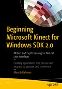
Compile the code to check your results. They should look something along the lines of Figure 3-1, minus Redmond bear.
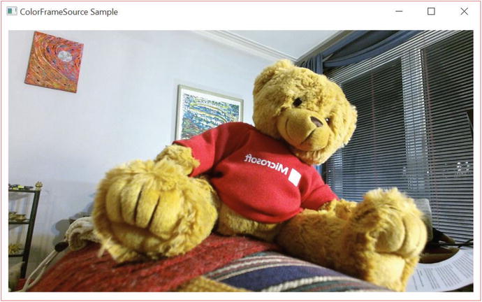
Figure 3-1. A Kinect application displaying a video feed, featuring Redmond bear
Well, there you go: your first application streaming live data directly from the Kinect. It is a bit bland for now, not even as featured as the default camera-viewing app provided with Windows was. Let us try to extend it by bundling some additional functionality. At the very least, every camera app should be able to take a screenshot, right?
Taking a Screenshot
Some of you have probably already thought of ways to grab a screenshot from the application. If not, take a couple of moments to think through how you could potentially do this. It seems simple enough, and there is more than one right way to achieve the desired result. The most common first guesses on how to do this are the following: grabbing and saving data from a frame, taking a snapshot of our UI, or saving our WriteableBitmap. Out of these options, the third one is the practical one and is how Microsoft does it in their samples.
Grabbing and saving from a frame would not be ideal, at least not with how our application is currently structured. When the screenshot button is clicked on the UI, an event is raised, and we manage to encode a picture file in its handler. We would have no convenient access to the ColorFrameSource in there, as all that logic and data is located in the ColorFrame event handler. Even if we did, there is no guarantee that there is a frame available for us to pick from at the instant the screenshot button is clicked. This is where polling could have been useful had we not gone with an event-driven model. We could poll for a frame to use as the basis for our screenshot. We could choose to cache a frame in the event handler and call on that, but seeing as our image already has a copy of the data, that would be redundant.
While it is possible with WPF to take a snapshot of our UI element, it is much more straightforward to simply save an image from its original source, the WriteableBitmap. It is already a bitmap, so we can encode it into a picture file with relative ease.
The code for adding screenshot functionality requires very few modifications to the application. Specifically, we will be adding a namespace reference, an event handler method , as shown in Listing 3-5, and a button on the UI, as shown in Listing 3-6. The namespace that we need to add is System.IO, which will provide us with methods with which to save an image file to the drive.
Listing 3-5. MainWindow.xaml.cs Screenshot Event Handler
//add to the Using sectionusing System.IO;//Directly after the MainWindow_Closing methodprivate void ScreenshotButton_Click(object sender, RoutedEventArgs e){if (this.colorBitmap != null){BitmapEncoder encoder = new PngBitmapEncoder();encoder.Frames.Add(BitmapFrame.Create(this.colorBitmap));string photoLoc = Environment.GetFolderPath(Environment.SpecialFolder.MyPictures);string time = System.DateTime.Now.ToString("d MMM yyyy hh-mm-ss");string path = Path.Combine(photoLoc, "Screenshot " + time + ".png");try{using (FileStream fs = new FileStream(path, FileMode.Create)){encoder.Save(fs);}//provide some confirmation to user that picture was taken}catch (IOException){//inform user that picture failed to save for whatever reason}}}
None of the code involved in capturing and saving an image is from the Kinect API. We are using code from the System.Windows.Media.Imaging and System.IO namespaces. After checking whether our WriteableBitmap has any data in it, we create a new PngBitmapEncoder, to which we add our WriteableBitmap as a BitmapFrame in encoder.Frames.Add(BitmapFrame.Create(this.colorBitmap));.
Note
Why does BitmapEncoder encoder have a Frames property that seems like it could accept more than one frame, when a PNG could only possibly have one? BitmapEncoder can also encode file types such as GIF that naturally have multiple frames. Adding more than one frame to the encoder for a file type such as PNG or JPEG will result in the subsequent frames being discarded. You can use this functionality to create your own GIF camera with the Kinect if you so desire.
After grabbing the location of our My Pictures folder and a unique timestamp to discourage our screenshot from overwriting prior ones, our encoder saves the screenshot to our desired path using .NET’s FileStream class. As with any input/output operation, this is wrapped in a try/catch block to handle the casual error (e.g., lack of disk space, no write access, and so on).
In MainWindow.xaml we will add the XAML for the Button UI element directly after the Viewbox UI element but inside the Grid UI element with which we will take our screenshots.
Listing 3-6. MainWindow.xaml Screenshot Button Markup
<Grid Margin="10">...</Viewbox><Button Grid.Row="2" Content="Screenshot" Height="Auto" HorizontalAlignment="Left" VerticalAlignment="Center" Margin="10" Click="ScreenshotButton_Click" /></Grid>
Most of the Button attributes are merely decorative. The important thing is to assign the event handler from our code-behind for when the button is clicked, which we accomplish with Click="ScreenshotButton_Click".
If you open our app now, you should be able to click the Screenshot button. There’s no picture-taken confirmation (though you can easily include this), so to find out if it worked, go visit your My Pictures folder. Now you can go share your beautiful Kinect picture on social media or the like. (Maybe on Snapchat. . . . oh wait, never mind; I forgot they took down 6snap.)
ColorFrameSource in Windows Store Apps
While the Kinect APIs are very similar for both platforms, the platform APIs are not, so there are some minor differences in how the apps are built. In the case of displaying ColorFrameSource data, we have to work around the Windows Store App version of WriteableBitmap, which is not the same as that of WPF.
The overall code structure for the Windows Store Application will look similar. Instead of the System.Windows.Media namespaces, we will have to use the Windows.UI.Xaml.Media and Windows.UI.Xaml.Media.Imaging namespaces, which have their own version of the WriteableBitmap class. Additionally, at the time of writing, instead of the Microsoft.Kinect reference we have been using all along, we will have to rely on the WindowsPreview.Kinect namespace. Do not let the name fool you, as the API is still pretty complete.
Note
If you are following along with the ColorBasics-XAML sample in the SDK Browser, you might be unable to compile. Chances are you got a System.IO.FileNotFoundException on the GetDefault method of KinectSensor. Do not fret, as this is just a result of the app retargeting Windows 8.1 and can be easily remedied. Visit the Reference Manager (can be accessed in Solution Explorer) and then the Extensions section in the menu labeled Windows 8.1. You will see a yellow caution sign next to Microsoft Visual C++ Runtime Package. You have to unselect that and choose Microsoft Visual C++ 2013 Runtime Package for Windows, which at version 12 is one version number ahead of the package it is replacing. The program should now compile.
Our initial bootstrapping code will only have a one-line difference (Listing 3-7).
Listing 3-7. MainPage.xaml.cs Data Source Bootstrapping and Variable Assignment in Windows Store Apps
public MainPage(){this.kinect = KinectSensor.GetDefault();this.colorFrameReader = this.kinect.ColorFrameSource.OpenReader();this.colorFrameReader.FrameArrived += this.Reader_ColorFrameArrived;FrameDescription colorFrameDescription = this.kinect.ColorFrameSource.CreateFrameDescription(ColorImageFormat.Rgba);this.colorBitmap = new WriteableBitmap(colorFrameDescription.Width, colorFrameDescription.Height);this.kinect.Open();this.DataContext = this;this.InitializeComponents();}...
In contrast to what we saw in Listing 3-2, Listing 3-7 shows how the Windows Store App version of WriteableBitmap’s constructor only takes two inputs—a width and a height. This means it is dumb in regards to the image’s format and quality, unlike WPF’s WriteableBitmap. I have included the rest of the constructor’s code to demonstrate the parity between both APIs.
The remaining brunt of the code differences are found in the Reader_ColorFrameArrived event handler.
Listing 3-8. MainPage.xaml.cs ColorFrameReader Event Handler in Windows Store Apps
private void Reader_ColorFrameArrived(object sender, ColorFrameArrivedEventArgs e){using (ColorFrame colorFrame = e.FrameReference.AcquireFrame()){if (colorFrame != null){FrameDescription colorFrameDescription = colorFrame.FrameDescription;if ((colorFrameDescription.Width == this.colorBitmap.PixelWidth) && (colorFrameDescription.Height == this.colorBitmap.PixelHeight)){if (colorFrame.RawColorImageFormat == ColorImageFormat.Bgra){colorFrame.CopyRawFrameDataToBuffer(this.colorBitmap.PixelBuffer);}else{colorFrame.CopyConvertedFrameDataToBuffer(this.colorBitmap.PixelBuffer, ColorImageFormat.Bgra);}colorFrameProcessed = true;}}}if (colorFrameProcessed){this.colorBitmap.Invalidate();}}
We see in Listing 3-8 that the processes of getting frames from the reader and the data integrity checks are all still the same. Pushing data into a WriteableBitmap for Windows Store Apps consists of calling the CopyRawFrameDataToBuffer method of ColorFrame and specifying the target buffer as the WriteableBitmap’s PixelBuffer. We also have the option of converting the raw data to another format on the spot with the CopyConvertedFrameDataToBuffer method, which takes the target buffer and the target format as inputs.
Finally, take note of the colorFrameProcessed Boolean and the colorBitmap.Invalidate(); method statement. We do not have to lock and unlock the WriteableBitmap like in WPF. Invalidate() requests a redraw of the bitmap instead and replaces it with our data, pushing the changes to the UI. Speaking of which, the UI code necessitates virtually no alterations. All we have to do on that end is change the top-level Window tags to Page tags and its Closing attribute to an Unloaded attribute. I suggest you create a new Windows Store App project in Visual Studio to get the markup right.
Before we run our application, there is one last step we must undertake before we can launch. Windows Store Apps require the user to grant permissions, as with iOS or Android apps. You need to declare these capabilities in the app manifest or you will not be able to access the Kinect. To do this, visit the Solutions Explorer and open the Package.appxmanifest file. In the Capabilities tab, enable the Microphone and Webcam capabilities, like in Figure 3-2. If you made all the correct changes, your Windows Store App should now stream video exactly like the WPF application did.
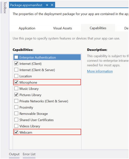
Figure 3-2. Permissions enabled in the Capabilities tab of the app manifest
Taking Another Screenshot
Windows Store Apps also have a different set of APIs to handle files and image encoding, so the code for taking screenshots is different as well. We will be saving images to the My Pictures folder, so you have to enable the Pictures Library permission in the app manifest, as depicted in Figure 3-2. We need to include a few more namespaces, namely System, System.Runtime.InteropServices.WindowsRuntime, Windows.Graphics.Imaging, Windows.Storage, and Windows.Storage.Streams.
As we did with the WPF example, add a Button element to the XAML code and give it an event handler for when it is clicked. You might need to change the color of the button to make it appear, as sometimes it shares the same color as the background. The rest of the code alterations take place in the event-handler body, as shown in Listing 3-9.
Listing 3-9. MainPage.xaml.cs Screenshot Event Handler in a Windows Store App
private async void ScreenshotButton_Click(object sender, RoutedEventArgs e){StorageFolder picFolder = KnownFolders.PicturesLibrary;StorageFile picFile = await picFolder.CreateFileAsync("Kinect Screenshot.png",CreationCollisionOption.GenerateUniqueName);using (IRandomAccessStream stream = await picFile.OpenAsync(FileAccessMode.ReadWrite)){var encoder = await BitmapEncoder.CreateAsync(BitmapEncoder.PngEncoderId, stream);Stream pixelStream = colorBitmap.PixelBuffer.AsStream();byte[] pixels = new byte[pixelStream.Length];await pixelStream.ReadyAsync(pixels, 0, pixels.Length);encoder.SetPixelData(BitmapPixelFormat.Bgra8,BitmapAlphaMode.Straight,(uint)colorBitmap.PixelWidth,(uint)colorBitmap.PixelHeight,96.0, 96.0,pixels);await encoder.FlushAsync();}}
We have made a small edit to the event handler method header. We have added the async keyword to modify the method and let the compiler know that there is asynchronous code in its body. Our input and output operations need to be done asynchronously so as to not lock up the UI thread while in operation. Within the method, we first find the My Pictures folder and create a PNG image within it. The CreateFileAsync method conveniently handles collisions as we desire, so we tell it to make unique files each time instead of having ourselves add unique timestamps programmatically.
We create a stream with the PNG file and a PNG BitmapEncoder to write to it. We create another stream called pixelStream from our WriteableBitmap’s data buffer and use it to write to an array of bytes. Then, the encoder sets the pixel data of our PNG using this array. The BitmapAlphaMode input in the SetPixelData method refers to how we want to save the alpha values to our PNG. Sometimes our final image is in a format that does not measure opacity, so we can choose to ignore or apply opacity to the color channels by multiplying the color values by the alphas. We will simply use the alphas that we already have in hand, thus the Straight option. The two 96.0 values are the horizontal and vertical dpis, respectively. We call the FlushAsync method of encoder to finalize the image operations. After it is called, we can make no more alterations to the image. Your Windows Store App should now be able to take pictures just as well as the WPF application did.
Tip
The await operator forces the code to suspend the execution of a method until it is completed. Meanwhile, control is returned to the caller of the method in a bid to keep the application from blocking.
Casual Image Manipulation
So far we have been copying our Kinect’s color data directly to the WriteableBitmap construct through its buffer. We are not obliged to simply hand the data off to the WriteableBitmap with the Kinect API calls we saw earlier. We can also opt to view the pixel data individually and make alterations. We were able to access the pixel data in the Windows Store App screenshot event handler by making a stream from the WriteableBitmap, but the Kinect API has methods to perform this before the data even hits the WriteableBitmap.
Why would we want to alter the pixel data? If you have ever used Instagram, Snapchat, or Photoshop (or GIMP!) you have probably applied a filter to one of your grams, snaps, or .psds (or .xcfs!). Seeing as images essentially store all their data as numbers, we can apply mathematical functions to transform this data and ultimately change how the image will look like based on these functions. When some application applies a filter or a digital affect such as red-eye removal, we are applying the necessary mathematical functions to make some data alteration globally in the image or locally on certain pixels.
Tip
How are numerical values used to describe images? Each pixel is described by a handful of bytes describing the color makeup of the pixel. A WriteableBitmap image with a BGRA32 format has three color channels and an opacity channel. Each color channel, Blue, Green, and Red, as well as the opacity channel, Alpha, is described with an 8-bit value (8 x 4 = 32, hence BGRA32). The 8-bit value, which goes from 0 to 28 – 1 (255), describes the intensity of the color channel in the pixel. A value of 0 refers to none of the color channel being present in the pixel, a value of 255 means the full intensity is present, and a value in between both extremes means a certain percentage of the color channel is present. The opacity channel describes how transparent the pixel is, with 0 being invisible, 255 being completely opaque, and numbers in between representing various degrees of transparency. The three color channels work like primary colors to make up other colors. Thus, Red 255, Blue 255 and Green 0 can be used to describe purple, and Blue 230, Green 230 and Red 0 can be used to describe a shade of cyan.
We will not go on to apply Instagram-caliber filters on our images right now, as that is beyond the scope of the chapter, but we will explore the procedure to access and manipulate the image data before it is displayed to the user.
Displaying ColorFrameSource Data with a Byte Array
Starting with the Kinect camera-viewing application we just built in the previous section, we will make some adjustments to obtain the image data inside of a byte array instead of a buffer.
Listing 3-10. MainPage.xaml.cs Variable Initialization for Color Data with Use of Byte Array
public sealed partial class MainPage : Page{private KinectSensor kinect = null;private ColorFrameReader colorFrameReader = null;private WriteableBitmap colorBitmap = null;private readonly uint bytesPerPixel;private byte[] colorPixels = null;...
In Listing 3-10, we see the variable initialization stage of our application. KinectSensor, ColorFrameReader, and WriteableBitmap all make a return. The structure of the code is still the same. What will change is how WriteableBitmap reads the data from our color frames. Previously, we could copy our data directly to the WriteableBitmap’s back buffer/pixel buffer, with an IntPtr or IBuffer provided by the Kinect API. Instead, we will now provide an array of bytes. colorPixels will be this array. Earlier, I mentioned that RGBA consisted of 3 bytes of color data + 1 byte of alpha opacity per pixel, for a total of 4 bytes per pixel. bytesPerPixel will hold this value as garnered from the ColorFrameSource. We could have resorted to using the literal four instead of creating a whole variable, but since the bytes per pixel change based on the color format, we can set it up so that we do not have to manually switch it when we change the format.
Seeing as we introduced two new variables, the bootstrap process is different as well (Listing 3-11).
Listing 3-11. MainPage.xaml.cs Bootstrapping and Variable Assignment for Color Data with Use of Byte Array
public MainPage(){this.kinect = KinectSensor.GetDefault();this.colorFrameReader = this.kinect.ColorFrameSource.OpenReader();this.colorFrameReader.FrameArrived += this.Reader_ColorFrameArrived;FrameDescription colorFrameDescription = this.kinect.ColorFrameSource.CreateFrameDescription(ColorImageFormat.Rgba);this.bytesPerPixel = colorFrameDescription.BytesPerPixel;this.colorPixels = new byte[colorFrameDescription.Width * colorFrameDescription.Height * this.bytesPerPixel];this.colorBitmap = new WriteableBitmap(colorFrameDescription.Width, colorFrameDescription.Height);this.kinect.Open();this.DataContext = this;this.InitializeComponent();}...
In Listing 3-11, we added two new lines preparing the colorPixels data array. Since colorPixels will hold the bytes of every pixel in our image, we are declaring its total size as the number of bytes per pixel for the relevant format multiplied by the total number of pixels. We get the bytes per pixel directly from the ColorFrameDescription, which takes into account the image format that we chose (RGBA in our case).
The rest of the code modification is in the event handler for the color frames (Listing 3-12).
Listing 3-12. MainPage.xaml.cs ColorFrameReader Event Handler for Direct Access to Pixel Data
private void Reader_ColorFrameArrived(object sender, ColorFrameArrivedEventArgs e){using (ColorFrame colorFrame = e.FrameReference.AcquireFrame()){if (colorFrame != null){FrameDescription colorFrameDescription = colorFrame.FrameDescription;if ((colorFrameDescription.Width == this.colorBitmap.PixelWidth) && (colorFrameDescription.Height == this.colorBitmap.PixelHeight)){if (colorFrame.RawColorImageFormat == ColorImageFormat.Bgra){colorFrame.CopyRawFrameDataToArray(this.colorPixels);}else{colorFrame.CopyConvertedFrameDataToArray(this.colorPixels, ColorImageFormat.Bgra);}Stream pixelStream = colorBitmap.PixelBuffer.AsStream();pixelStream.Seek(0, SeekOrigin.Begin);pixelStream.Write(colorPixels, 0, colorPixels.Length);colorFrameProcessed = true;}}}if (colorFrameProcessed){this.colorBitmap.Invalidate();}}
Instead of the CopyRawFrameDataToBuffer and CopyConvertedFrameDataToBuffer methods we used earlier, we are using their byte-array equivalents, CopyRawFrameDataToArray and CopyConvertedFrameDataToArray, respectively. Once the pixel data is copied to the arrays, we write to the WriteableBitmap in way a similar to that used when we read from it in the screenshot code: we create a stream from its pixel buffer. The Seek method of our Stream pixelStream is used to set the position of where we will write in the stream. The SeekOrigin.Begin input sets it to the start of the stream, and the first input, 0, is the offset from the beginning position where we want to start. In the Write method of Stream, we specify that we want to write with the contents of the byte array colorPixels for the entire length of the array. Again, the 0 here is also the offset.
For now, the rest of the code is the same. Make sure that the System.IO namespace is included so that we can use the Stream class. Your program should run just as if you had used a buffer to write to WriteableBitmap.
Manipulating Image Pixel Data
We only really benefit from having the image data available as a byte array if we plan to manipulate it. Let us make a very simple alteration. As mentioned earlier, each pixel has three color channels—Blue, Green and Red–with 8 bits of intensity, or 256 different values. We will be making a filter that hides the green and blue channels of the image, meaning we will set their respective intensities to 0.
In our Reader_ColorFrameArrived event handler, our code will find itself in the lines right after ColorFrame data has been copied to an array and right before that array is used by a stream to write to the WriteableBitmap (Listing 3-13).
Listing 3-13. MainPage.xaml.cs ColorFrameReader Event Handler Manipulating Color Data Byte Array Values
...colorFrame.CopyConvertedFrameDataToArray(this.colorPixels, ColorImageFormat.Bgra);}for (uint i = 0; i < colorPixels.Length; i += bytesPerPixel){colorPixels[i] = 0x00;colorPixels[i + 1] = 0x00;}Stream pixelStream = colorBitmap.PixelBuffer.AsStream();...
In Listing 3-13, the for loop cycles through each pixel in the image and sets the first two channels, Blue and Green, to 0 intensity. We are iterating by the value of bytesPerPixel, which is 4, because the array’s indices contain bytes, 4 for each pixel. When we go through the first 4 bytes, we have covered the first pixel and applied the desired operations to its color channels. Since we are manipulating bytes, we set the pixel color channel intensity values using hexadecimal notation. Hence, when we say colorPixels[i + 1] = 0x00, we are saying the green channel (the second channel in BGRA) has an intensity of 0.
Compile the program, and you should see nothing but red throughout the image (Figure 3-3).
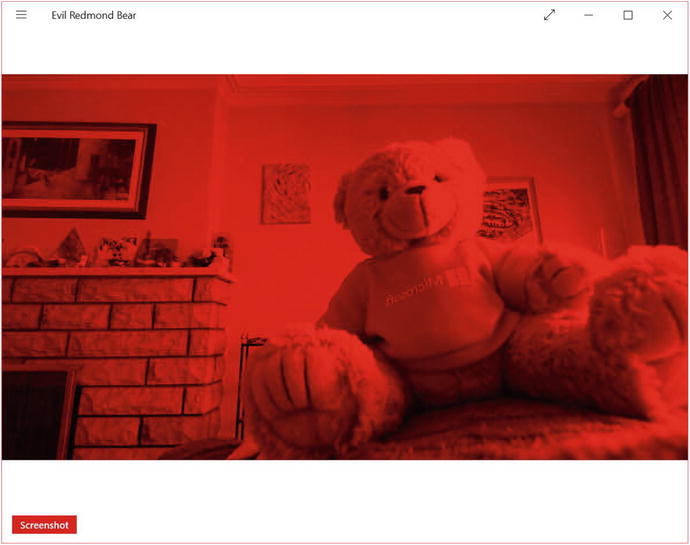
Figure 3-3. Redmond bear shows his true colors
On my i5 Surface Pro 2, tinting the picture red resulted in a 7 to 10 point higher reading for CPU usage in Task Manager. Generally, we will want to avoid doing heavy image processing in WPF without C++ interop because of performance issues. After all, we are looping through and applying operations to over 2 million pixels, 30 times a second! You can compile and run your program in a Release configuration to improve performance.
InfraredFrameSource: Infrared Image Data
Unlike its predecessor, the Kinect for Windows v2 can give us unfettered access to its infrared camera without having to shut off the color camera. The resolution is much better than in Kinect for Windows v1, and the IR dot speckle pattern no longer clouds the resulting image. Unlike with our (or any average) color camera, our infrared camera ignores ambient lighting conditions (as depicted in Figure 3-4) and can thus see in the dark and through other occlusions, such as smoke. This is particularly helpful in situations where the texture of an object is important, which is why infrared cameras are also used by Windows Hello’s face-detection algorithm. All this means more magic™ with which to design and build our NUI applications!

Figure 3-4. Footage from the Kinect’s infrared camera. All three of the lights on the lamp are lit, and the author is holding out a lit candle as well. The lamp light is not picked up, and only the faint outline of the candle flame is visible. In the Kinect for Windows v1, the entire flame would have been picked up .
In this chapter, we will cover how to extract and display the Kinect’s infrared data. This data can be used for various purposes, such as tracking active markers in motion-capture (mocap) systems or green-screening, but that is beyond the scope of this section.
Displaying Infrared Data
As I mentioned a few times before, the pattern of creating a reader to get frames from a data source is the same for all of the Kinect’s sensory data, so to see how to write the scaffolding setup for this code, revisit the code for ColorFrameSource, particularly Listings 3-1, 3-2, and 3-3. The only differences in the bootstrapping process are the WriteableBitmap image format, which is Gray32Float, and the names of the data source, reader, frame, and frame description. These are InfraredFrameSource, InfraredFrameReader, InfraredFrame, and InfraredFrameDescription, respectively.
The actual differences in how the data is rendered are entirely located in the InfraredFrameReader event handler and its associated methods. Listing 3-14 shows an example for a WPF .NET application.
Listing 3-14. InfraredFrameReader Event Handler and Helper Method
...//Private variables declared before class constructorprivate const float InfrDataScale = 0.75f;private const float InfrMinVal = 0.01f;private const float InfrMaxVal = 1.0f;//Private variable for the InfraredFrameReaderprivate InfraredFrameReader irFrameReader = null;/*Our WriteableBitmap is named infrBitmap and created in a similar manner to the ColorFrameSource examples, except the PixelFormat's input is PixelFormats.Gray32Float instead of PixelFormats.Bgr32*/private WriteableBitmap infrBitmap = null;...//Logic inside the MainWindow() Constructor//public MainWindow() {//...//InfraRed Initializationthis.irFrameReader = this.kinect.InfraredFrameSource.OpenReader();this.irFrameReader.FrameArrived += Reader_InfraredFrameArrived;FrameDescription infraRedFrameDescription = this.kinect.InfraredFrameSource.FrameDescription;this.infrBitmap = new WriteableBitmap(infraRedFrameDescription.Width, infraRedFrameDescription.Height, 96.0, 96.0, PixelFormats.Gray32Float, null);// ... }private void Reader_InfraredFrameArrived(object sender, InfraredFrameArrivedEventArgs e){using (InfraredFrame infrFrame = e.FrameReference.AcquireFrame()){if (infrFrame != null){using (KinectBuffer infrBuffer = infrFrame.LockImageBuffer()){if ((infrFrame.FrameDescription.Width * infrFrame.FrameDescription.Height) == (infrBuffer.Size / infrFrame.FrameDescription.BytesPerPixel)){this.ProcessInfraredFrameData(infrBuffer.UnderlyingBuffer, infrBuffer.Size, infrFrame.FrameDescription.BytesPerPixel);}}}}}private unsafe void ProcessInfraredFrameData(IntPtr infrFrameData, uint infrFrameDataSize, uint bytesPerPix){ushort* frameData = (ushort*)infrFrameData;this.infrBitmap.Lock();float* backBuffer = (float*)this.infrBitmap.BackBuffer;for (int i = 0; i < (int)(infrFrameDataSize / bytesPerPix); ++i){ushort irValue = frameData[i];float irRange = (float)(irValue - ushort.MinValue ) / (float)(ushort.MaxValue - ushort.MinValue );float ir_desiredRange = (float)(irRange * (1 - InfrMinVal)) + InfrMinVal;float ir_desiredRange_withBrightness = ir_desiredRange * InfrDataScale;backBuffer[i] = Math.Min(InfrMaxVal, ir_desiredRange_withBrightness);}this.infrBitmap.AddDirtyRect(new Int32Rect(0, 0, this.infrBitmap.PixelWidth, this.infrBitmap.PixelHeight));this.infrBitmap.Unlock();}
Listing 3-14 is based off the InfraredBasics-WPF code sample in the SDK Browser. The code is somewhat more involved than the equivalent code for the exploitation of the ColorFrameSource. While we could have gone the simpler route, we opted to make performance optimizations by relying on pointers for the processing of our infrared data.
Since we are using pointers to directly access memory in managed code, we need to add the unsafe keyword to our ProcessInfraredFrameData method header. Additionally, we need to set the /unsafe compiler option as well. To do this, visit the Project Properties page under the Project tab in Visual Studio. Next, go to the Build tab on the Properties page and check the Allow unsafe code checkbox, as in Figure 3-5.
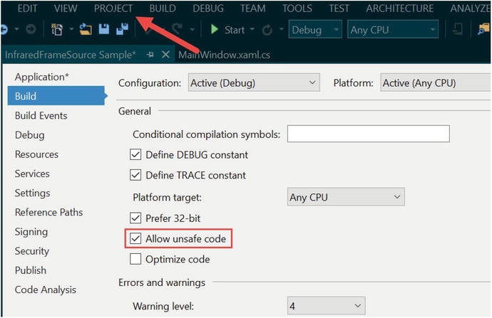
Figure 3-5. Allowing unsafe code in Visual Studio
Our frame is acquired in the event handler, and after checking the integrity of our data we pass a reference to the data to our helper method so as to process and display the infrared data. We take an IntPtr to our infrared frame buffer, as well as its size and its number of bytes per pixel as inputs to our helper method. As each pixel of the infrared data is an unsigned 16-bit value, we cast the infrared frame’s data buffer to a ushort (unsigned short, 16-bit integer) pointer to access its values. Similarly, we cast the WriteableBitmap’s BackBuffer to a float pointer. This is because, unlike our RGBA sample, our grayscale picture is described in fractions of 0 to 1 with Gray32Float. The WriteableBitmap is locked before this to prevent updates to the UI while we work on it.
To transform the 16-bit infrared intensity values from the Kinect into Gray32Float values that can be displayed by the WriteableBitmap, we must normalize them (see the note for further explanation). We loop through all the ushorts in frameData and apply our normalization algorithm to each of them, then write the result in the WriteableBitmap’s BackBuffer. Our loop’s termination condition is the total byte size of the infrared frame divided by its bytes per pixel value (which is 2). This is because ushort values are 2-byte values; thus, when we iterate through them we go by 2 bytes each time, and consequently the number of ushorts to go through is half the total size of the infrared frame in bytes.
While performing the normalization , we make use of three float variables: InfrMaxVal, InfrMinVal, and InfrDataScale. InfrMaxVal and InfrMinVal represent the maximum and minimum desired values for the gray values displayed on our WriteableBitmap. In Gray32Float, each pixel can be one of over 4 billion shades of gray (beat that, you 6-bit drivel of a romance novel!), and we can thus set a “wall” so that extreme (perhaps erroneous) infrared intensity values picked up by our sensor do not appear lighter or darker than certain desired shades of gray. InfrDataScale is used to scale the gray shades so that they appear lighter or darker. Larger values for this variable will result in a brighter picture, whereas as lower values will result in a darker picture. Numbers between 0.75f and 1f work well for this.
Note
Normalization refers to the adjustment of values from different scales to correspond to a single common scale. In our case, infrared data has 216 (65,536) different values while WriteableBitmap supports up to 232 (4,294,967,296) different values. However, our Gray32 value is actually measured in floats from 0 to 1, as we set the PixelFormats to Gray32Float. Since we are normalizing on a 0 to 1 scale, the formula we would use is as follows:
![]()
Where x represents the infrared intensity value we want to normalize, x min its lowest possible value, and x max its highest possible value. Our x min and x max values are 0 and 65535 (or ushort.MaxValue), respectively. If we ignore the x min (since it is 0), the formula should be familiar to you, as it is the method with which we calculate percentages (as any student who calculates their test scores can attest to). To ensure that our value is normalized within the range of desired minimum and maximum of displayable gray intensities and not merely the entire spectrum of 0 to 1, we apply another formula:
x dMin to dMax = x 0 to 1 × (1 – x desiredMin ) + x desiredMin
When we multiply by (1 – x desiredMin ) we make it so that the value can only be within that range, and then we add the x desiredMin to offset the value and make sure it starts at our desired minimum. For example, if our desired minimum is 0.8, we do 1 – 0.8, which gives us a range of [0, 0.2]. If we add this to our desired minimum, which is 0.8, we get a range of [0.8, 1].
While normally this would give us a range between our desired minimum and desired maximum, we have a scaling value to control brightness. Multiplying x dMin to dMax by this can result in a value larger than the desired maximum, which is why we apply the Math.Min() function to make sure that this does not happen.
After normalizing the values, we set the region to be written in the WriteableBitmap with the AddDirtyRect method and unlock it so that it can update the UI image again, just like in the ColorFrameSource example. Compiling and running the code should result in an infrared video feed similar to that seen in Figure 3-4.
DepthFrameSource: Depth Image Data
The Kinect’s depth-sensing capability is very possibly its most interesting and useful feature. Many have purchased the Kinect for that functionality alone. Color cameras are common, and gesture, skeletal, and facial recognition can always be implemented through computer vision techniques. “Cheap and easy-to-use depth camera,” however, is a category that the Kinect has pioneered and owned.
As you would guess from its name, the Kinect’s depth camera gives us details about the depth of objects in its field of view. Relying on the power of math and algorithms, we can use this data to measure objects and implement custom tracking systems. While it is possible to go very in depth (sorry) with this data, in this portion of the book we will focus on techniques to extract it and process it for visualization.
Displaying Depth Data
Like InfraredFrameSource and ColorFrameSource, DepthFrameSource follows the same patterns and utilizes the analogous DepthFrameReader, DepthFrame, and DepthFrameDescription classes. As with the other image Data Sources, we will be creating a WPF application and including the Microsoft.Kinect, System.Windows.Media, and System.Windows.Media.Imaging namespaces in our project. We will still introduce some new variables, however. To deal with the processing of the depth data for visualization we have the code found in Listing 3-15.
Listing 3-15. MainWindow.xaml.cs Variable Initialization and Bootstrapping for Depth Data
public partial class MainWindow : Window{...//Other private variables such as KinectSensor and WriteableBitmap go here...// Declare the DepthFrameReaderprivate DepthFrameReader depthFrameReader = null;private FrameDescription depthFrameDescription = null;private const int MapDepthToByte = 8000 / 256;private byte[] depthPixels = null;public MainWindow(){.../*Kinect initialization, event handler assignment and etc. code. See listings 3-1, 3-2, 3-3 for more info.*/...this.depthFrameReader = this.kinect.DepthFrameSource.OpenReader();this.depthFrameReader.FrameArrived += Reader_DepthFrameArrived;this.depthFrameDescription = this.kinect.DepthFrameSource.FrameDescription;this.depthPixels = new byte[this.depthFrameDescription.Width * this.depthFrameDescription.Height];this.depthBitmap = new WriteableBitmap(this.depthFrameDescription.Width, this.depthFrameDescription.Height, 96.0, 96.0, PixelFormats.Gray8, null);...
We bring two new variables to the traditional concoction of XFrameSource-related variables. Depth data from the Kinect will be made available to us in 16-bit ushort values representing millimeter distances from the camera’s plane. We will be displaying this data in Gray8 format; thus, each pixel of our WriteableBitmap will be one of possible 256 shades of gray. The shades of gray will indicate how far the Kinect is from that position in the image. MapDepthToByte will be used to normalize the millimeter measurements for display in the WriteableBitmap. depthPixels is an array that will hold our normalized depth pixel values for rendering. We declare it with the size of 1 byte per pixel for the area of the image.
Our event handler for the DepthFrameReader and its associated helper will look somewhat like that of the InfraredFrameReader (Listing 3-16).
Listing 3-16. MainWindow.xaml.cs DepthFrameReader Event Handler and Helper Method
private void Reader_DepthFrameArrived(object sender, DepthFrameArrivedEventArgs e){bool depthFrameProcessed = false;using (DepthFrame depthFrame = e.FrameReference.AcquireFrame()){if (depthFrame != null){using (KinectBuffer depthBuffer = depthFrame.LockImageBuffer()){if ((this.depthFrameDescription.Width * this.depthFrameDescription.Height) == (depthBuffer.Size / this.depthFrameDescription.BytesPerPixel)){ushort maxDepth = ushort.MaxValue;this.ProcessDepthFrameData(depthBuffer.UnderlyingBuffer, depthBuffer.Size, depthFrame.DepthMinReliableDistance, maxDepth);depthFrameProcessed = true;}}}}if (depthFrameProcessed){this.depthBitmap.WritePixels(new Int32Rect(0, 0, this.depthBitmap.PixelWidth, this.depthBitmap.PixelHeight),this.depthPixels,this.depthBitmap.PixelWidth,0);}}private unsafe void ProcessDepthFrameData(IntPtr depthFrameData, uint depthFrameDataSize, ushort minDepth, ushort maxDepth){ushort* frameData = (ushort*)depthFrameData;for (int i = 0; i < (int)(depthFrameDataSize / this.depthFrameDescription.BytesPerPixel); ++i){ushort depth = frameData[i];this.depthPixels[i] = (byte)(depth >= minDepth && depth <= maxDepth ? (depth / MapDepthToByte) : 0);}}
Like the event handler for the InfraredFrameReader, we acquire our frame of data and check its integrity before passing it to a helper method for processing. Our helper method, ProcessDepthFrameData, also makes use of pointers to access the depth frame data; thus, we must also mark the method header with the unsafe keyword and let the compiler know to allow unsafe code execution (see Figure 3-5).
ProcessDepthFrameData takes an IntPtr to the depth frame’s data buffer, its size, and our definitions for the closest and farthest depths to show. After creating a ushort pointer, we loop through the pixels in the frame and set the equivalent pixel in the WriteableBitmap to a normalized value if it is in between our desired maximum or minimum depth values; otherwise, we set it to 0 (or the color black). To normalize our depth data from millimeters to an 8-bit value, we divide the millimeter value by MapDepthToByte. If you recall, MapDepthToByte is equal to ![]() , and thus if we have a value such as 8000mm (which is the max measurable distance), we do
, and thus if we have a value such as 8000mm (which is the max measurable distance), we do ![]() , which is equal to 256, or pure white on a Gray8 WriteableBitmap. For a more thorough explanation of normalization, visit Listing 3-14 and its associated discussion.
, which is equal to 256, or pure white on a Gray8 WriteableBitmap. For a more thorough explanation of normalization, visit Listing 3-14 and its associated discussion.
Tip
Confused by the ? x : y operator? The ternary, or conditional, operator simply returns the first value (x) if the expression it is operating on is true and the second value (y) if it is false. Take a look at the following expression:
string wealth = (name == "Bill Gates") ? "billionaire" : "not a billionaire";If the string name is equal to “Bill Gates”, the string wealth will be set to “billionaire”; otherwise, it will be set to “not a billionaire”. While this should be an element of any experienced developer’s arsenal, as programming becomes more accessible to the general population and younger audiences, the if/else-statement equivalent is often preferred for readability, and thus some readers may have not encountered the use of this operator previously.
After our entire WriteableBitmap is filled with depth data, we return control to Reader_DepthFrameArrived and finish the rendering process of the WriteableBitmap. If all goes well, you should get an image similar to Figure 3-6. The lightest shades of gray represent the farthest distances and vice versa. Any black pixels represent locations where the Kinect could not determine the depth at all. The black jitter is a result the uncertainty of the Kinect in determining depth distances at certain locations and ranges. This can be reduced with smoothing techniques and was not implemented by the Kinect development team, as different applications have different requirements for performance and jitter filtering.

Figure 3-6. The author’s living room visualized in a depth image. Can you spot Redmond bear?
Visualization Techniques
Although the grayscale representation of our depth data is cool to look at, it is not very pretty, nor is it very useful. It is simply a proof of concept; we can view the depth data through other visualizations to appreciate and utilize it.
Color Gradient Depth Feed
We are not obliged to use a mundane gray to display our depth feed. On the Internet or in demo apps such as Kinect Evolution you will often see the depth feed shaded with various colors. We can choose to do that too.
A common depth feed coloring technique is the color gradient. Right now, our depth feed has a gradient going from black to white. We can change this so that it goes from two or more different colors to white. The first step to achieving this is to change our color format from Gray8 to a more appropriate format. We can choose anything, but Bgra32 is a good bet for any basic color work.
We start by changing the format of our WriteableBitmap and the size of the byte array that will render data to it (Listing 3-17).
Listing 3-17. Variable Declaration for Colorized Depth Feed
//Inside the MainWindow() Constructorpublic MainWindow() {// ...this.depthPixels = new byte[this.depthFrameDescription.Width * this.depthFrameDescription.Height * 4];this.depthBitmap = new WriteableBitmap(this.depthFrameDesription.Width, this.depthFrameDescription.Height, 96.0, 96.0, PixelFormats.Bgra32, null);// ...
The depthPixels array’s size must be increased to accommodate the bytes from the additional color channels it will now hold for each pixel. We multiply the total number of pixels by 4, as we have 4 bytes of color data per pixel. Remember, Bgra32 is 32 bits of color data, which is equivalent to 4 bytes.
Inside our ProcessDepthFrameData method from earlier, we will have to change how we put data into our depthPixels array, as it is now four times the size (Listing 3-18).
Listing 3-18. Processing Depth Data for Bgra32 WriteableBitmaps
private unsafe void ProcessDepthFrameData(IntPtr depthFrameData, uint depthFrameDataSize, ushort minDepth, ushort maxDepth){ushort* frameData = (ushort*)depthFrameData;int colorByteIndex = 0;for (int i = 0; i < (int)(depthFrameDataSize / this.depthFrameDescription.BytesPerPixel); ++i){ushort depth = frameData[i];// Set Blue Channelthis.depthPixels[colorByteIndex++] = (byte)(depth >= minDepth && depth <= maxDepth ? depth : 0);// Set Green Channelthis.depthPixels[colorByteIndex++] = (byte)(depth >= minDepth && depth <= maxDepth ? depth : 0);// Set Red Channelthis.depthPixels[colorByteIndex++] = 0;// Set Alpha /transparent Channelthis.depthPixels[colorByteIndex++] = 255;}}
The same line is repeated twice—is that a printing error? Not quite. Since we have three color channels, we have to set the color value for each of them every time we iterate a single pixel. colorByteIndex tracks which channel we are inspecting in the depthPixels array. The fourth channel, the one for alpha, is always set to 255, the highest 8-bit value, because we always want full opacity. Before we try to get a color gradient between multiple colors for our image, let us get it working for one color. We set the red channel to 0 so that we can get different shades of cyan as the color of our depth feed.
The one last change needed in order to get our depth feed displaying data through Bgra32 must be made in the method so as to render the data to the WriteableBitmap (Listing 3-19).
Listing 3-19. WriteableBitmap’s WritePixel Method for Bgra32
// Inside the Reader_DepthFrameArrived() {// ...this.depthBitmap.WritePixels(New Int32Rect(0, 0, this.depthBitmap.PixelWidth, this.depthBitmap.PixelHeight),this.depthPixels,this.depthBitmap.PixelWidth * 4,0);// ...
The penultimate input for this particular configuration of the WritePixels method is the image’s stride. We must multiply by 4 since we now have 4 bytes per pixel worth of data. Note that we use the depthBitmap’s PixelWidth property and not its Width property, as the latter does not give us the width of the picture in pixels.
Tip
What’s a stride? A stride is the width of a single row of pixels in the image, rounded up to a 4-byte boundary. An easy way to calculate the stride for any image in WPF is to multiply the width of the image in pixels by the number of bytes per pixel. Thus, previously when our depthBitmap displayed the depth feed using the Gray8 format, our stride was simply the width of the WriteableBitmap, as Gray8 pixels are measured using 1-byte.
Compile and run the program when you have finished, and you should get something like Figure 3-7, but in cyan instead of magenta.

Figure 3-7. The author’s living room in a colorized depth feed. Magenta was obtained instead of cyan by setting the first and third color channels (Blue and Red, respectively) of each pixel with the depth value and setting the second color channel (Green) as 0.
Wait, what is this? What are the black bands repeated throughout the image? Keen readers will have noticed that I omitted the MapDepthToByte divisor from the depth-intensity calculation. Since our ushort depth value is not normalized, the color intensity goes from black to magenta every 0mm to 255mm and then restarts. This is because when the ushort value is converted to a byte value, we truncate it and take the last 8 bits of its 16-bit value. While this can make clustered objects harder to see, when compared to our 8-bit grayscale image in Figure 3-6, it definitely makes the shape of the room easier to visualize. The back wall is clearer, along with the curtains and the rear sofa. Additionally, we can make out the contours of some of the stickers on the HP printer box at the bottom left of the image. Unfortunately, it does give a bit more of a damned vibe to my living room.
Let us now apply the algorithm to get our depth feed mapped to a color gradient (Listing 3-20).
Listing 3-20. Depth Data Processed with a Color Gradient
private unsafe void ProcessDepthFrameData(IntPtr depthFrameData, uint depthFrameDataSize, ushort minDepth, ushort maxDepth){ushort* frameData = (ushort*)depthFrameData;int colorByteIndex = 0;for (int i = 0; i < (int)(depthFrameDataSize / this.depthFrameDescription.BytesPerPixel); ++i){ushort depth = frameData[i];float depthPercentage = (depth / 8000f);this.depthPixels[colorByteIndex++] = 0;this.depthPixels[colorByteIndex++] = (byte)(depth >= minDepth && depth <= maxDepth ? (depthPercentage) * 255 + (1 – depthPercentage) * 0 : 0);this.depthPixels[colorByteIndex++] = (byte)(depth >= minDepth && depth <= maxDepth ? (depthPercentage) * 0 + (1 – depthPercentage) * 255 : 0);this.depthPixels[colorByteIndex++] = 255;}}
The algorithm to apply a color gradient to our depth feed is not particularly difficult. We are trying to go from one color to another color, so as the depth increases, we use more of the color for the maximum depth and a smaller percentage of the color we started from. Since our colors are measured with three color channels, we do this for the intensity of each channel using the RGB component of the desired colors. This can be described by the following formula (using the Green channel as an example):
Green = G component of Color1 × Depth Percentage + G component of Color2 × (1– Depth Percentage)
In Listing 3-20, the colors I went for were Green and Red, whose BGR components are 0, 255, 0 and 0, 0, 255, respectively. The Blue channel is not used, so I set it to 0 from the get-go. When depthPercentage, which is a measure of how close we are to 8m (the official limit of the Kinect’s depth-sensing abilities), reaches 1, we want the depth to be colored green. Looking at the formula for the Green channel, we thus have 1 x 255 + (1 – 1) x 0 = 255. If we were at 4m, we would expect 50 percent green (and 50 percent red), so the formula for green would result in 0.5 x 255 + (1 – 0.5) x 0 = 127.5, which is rounded to 127. The resulting color gradient depth feed should look like that seen in Figure 3-8.
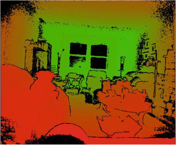
Figure 3-8. The depth feed under a Red-Green color gradient
We use colors in other ways to help us visualize the depth of a scene. Instead of having a linear gradient where we go from one color to another gradually, we can choose to have a handful of colors represent different ranges of depth. We could choose yellow for anything between 1 and 2 meters, green for anything between 2 and 3 meters, and so on. This would provide a legend as to where objects are positioned in a scene, rather than saying “it is kind of green and kind of red.” Fortunately, this is not difficult at all. It is simply a matter of making a handful of if statements for each color region (Listing 3-21).
Listing 3-21. Visualizing Depth Data with Color Regions
// Inside the ProcessDepthFrameData() {...// Replace all the logic inside the method with the following:ushort* frameData = (ushort*)depthFrameData;int colorByteIndex = 0;Color color = new Color();for (int i = 0; i < (int)(depthFrameDataSize / this.depthFrameDescription.BytesPerPixel); ++i){ushort depth = frameData[i];float depthPercentage = (depth / 8000f);if (depthPercentage <= 0) {color.B = 0;color.G = 0;color.R = 0;}if (depthPercentage > 0f & depthPercentage <= 0.2f) {color.B = 255;color.G = 0;color.R = 0;}if (depthPercentage > 0.2f & depthPercentage <= 0.4f) {color.B = 0;color.G = 255;color.R = 0;}if (depthPercentage > 0.4f & depthPercentage <= 0.6f) {color.B = 0;color.G = 0;color.R = 255;}if (depthPercentage >= 0.6f) {color.B = 0;color.G = 255;color.R = 255;}this.depthPixels[colorByteIndex++] = color.B;this.depthPixels[colorByteIndex++] = color.G;this.depthPixels[colorByteIndex++] = color.R;this.depthPixels[colorByteIndex++] = 255;}// ...
In Listing 3-21, we made use of WPF’s Color structure to keep track of our desired colors for the various regions. Each Color object has properties for Blue, Green, Red, and Alpha values that we can set. Our series of conditional statements simply determines which depth region a pixel falls in and then assigns its color. For example, in Figure 3-9, if our depth value for a pixel is between 20 percent and 40 percent of the maximum possible value of 8000mm, we set it as green. Looking at the image, we can instantly determine that any area colored green is between 1.6m and 3.2m. Of course, we could have picked smaller ranges and added more colors to make it even more practical. If you are measuring anything with this method, remember to take into account the fact that distances are measured from the camera’s plane. This means measuring by holding a ruler or tape perpendicular to the Kinect’s face. In Figure 3-10, you can see this imaginary plane, which is created by the x and y axes.

Figure 3-9. The author’s living room in bands of 1.6m (yellow is anything farther than 4.8m)

Figure 3-10. The camera measures depth perpendicular from the x–y plane, on the z-axis
Determining the Depth of a Pixel
You might be wondering at this point why, if we can get numerical depth measurements, are we wasting our time with colors? Fair enough. I do have to meet a page quota to have this book published, so bear with me. Let us make a tool that will allow us to determine the depth in millimeters of a particular pixel in an image.
Before I give you the code, let us consider the fact that the Kinect camera’s field of view, like most other cameras, is shaped like a pyramid, as in Figure 3-11. This means that if the Kinect sees a surface near it, the depth points represented in 3D space by the pixels are more packed together than if the Kinect sees a surface farther away. The x and y coordinates of our image therefore do not correspond to heights and widths in the real world.

Figure 3-11. The Kinect’s field of view. The blue 4 × 4 pixel grid closer to the Kinect is more densely packed than the 4 × 4 pixel grid farther from the Kinect. In reality, the Kinect has way more pixels, but a 4 × 4 grid was arbitrarily picked for demonstration purposes.
Since we want to access depth data outside of the DepthFrameReader event handler on a mouse click, we will have to store the depth data in some type of data structure. We could take the data from the byte array depthPixels that we used to write to our WriteableBitmap, but depth data is 16-bits, so we need something larger. We could use a Gray16 image format, or hold it in 2 of the 4 bytes in each RGBA color channel, but we will not bother with the hassle and instead will create another array to hold the depth data (Listing 3-22).
Listing 3-22. Getting Depth Distance for a Pixel on Mouse Click
...//among other private variables such as WriteableBitmap depthBitmapprivate int[] depthData = null;...public MainWindow(){...//other variables assigned herethis.depthData = new int[this.depthFrameDescription.Width * this.depthFrameDescription.Height];...}private unsafe void ProcessDepthFrameData(IntPtr depthFrameData, uint depthFrameDataSize, ushort minDepth, ushort maxDepth){ushort* frameData = (ushort*)depthFrameData;int index = 0;for (int i = 0; i <(int)(depthFrameDataSize / this.depthFrameDescription.BytesPerPixel); ++i){ushort depth = frameData[i];this.depthData[i] = depth;this.depthPixels[index++] = (byte)(depth >= minDepth && depth <= maxDepth ? depth : 0);this.depthPixels[index++] = (byte)(depth >= minDepth && depth <= maxDepth ? depth / MapDepthToByte : 0);this.depthPixels[index++] = (byte)(depth >= minDepth && depth <= maxDepth ? depth / MapDepthToByte : 0);this.depthPixels[index++] = 255;}}private void Image_MouseDown(object sender, System.Windows.Input.MouseEventArgs e){Point p = e.GetPosition(DepthImage);int index = ((int)p.X + ((int)p.Y * depthBitmap.PixelWidth));int depth = depthData[index];ToolTip toolTip = new ToolTip { Content = depth + "mm", FontSize = 36, IsOpen = true, StaysOpen = false };DepthImage.ToolTip = toolTip;}
We added an array of integers, depthData, to cache the depth for each pixel in the image every time we have a new frame. The depth data processing code was barely modified to accommodate this. We simply added a line, this.depthData[i] = depth;, to have it collect the depth every time we process a new pixel. An event handler called Image_MouseDown was added to be called whenever a pixel in our image is clicked. It gets the x and y coordinates of the pixel that was clicked, and we use it to find the corresponding pixel in our integer array. Our integer array is one-dimensional, whereas the picture coordinates are two-dimensional. The integer array stores each row of the image one after another, so we can multiply the y coordinate by the width of the image in pixels to find out how far into the integer array to go to get the desired depth data. To better imagine this, pretend our image is a 10-pixel by 10-pixel bitmap and we want to find the depth of the pixel at column 7 and row 5. The size of our integer array is 100. Counting from the top left and starting at 0, we get the pixel number as 5 x 10 + 6, or 56. The corresponding depth value in our integer array would be at index 56 as well. We start at 0, of course, as C# arrays start their indexes at 0.
To display the data, we create a tooltip UI element that pops up wherever on the image we clicked.
On the front end, we need to modify our Image tag to support the mouse-clicked event (Listing 3-23).
Listing 3-23. Image XAML for Getting Depth Distance of a Pixel on Mouse Click
<Image Name="DepthImage" Source="{Binding ImageSource}" Stretch="UniformToFill" MouseDown="Image_MouseDown" />In addition to adding the MouseDown event-handler tag for when the mouse is clicked, we also added the name DepthImage so that our event handler knows to which image to add its tooltip. After compiling the program, click on any pixel on the image to find out how far it is from the Kinect’s plane, as demonstrated in Figure 3-12.

Figure 3-12. Distance from the Kinect to the couch. The pixel that was clicked is located at the top-right corner of the tooltip.
Keen observers will again have noted why the image gets progressively yellower further in. In the code to set the intensity for each color channel, we divided the depth values for the Green and Red channels by the MapDepthToByte value, which we did not do for the Blue channel. Thus, the Blue channel has the wrapping effect throughout the image, whereas the Green and Red do not. If you have memorized some RGB values by now, you will know that Red + Green = Yellow.
Summary
In this chapter, we discovered that the Kinect’s color, infrared, and depth data can be conveyed by various means. Although there are convenient API methods to display the data to the UI, we can choose to inspect and manipulate the data to further enhance its use for our application’s users. The data is malleable and can be saved to the disk as images or cached in the application. It is only by taking advantage of all these capabilities that we can hope to build the best experience for our users.
In the next chapter, we will take advantage of the Kinect’s audio sensors and create applications by parsing vocal input.