
At the heart of a user’s desire to interact with the Kinect is the ability to physically manipulate a digital reality. It is an experience that is nigh on magical for most people. Just imagine if you were to obscure a Kinect from someone’s view and enable them to wield the environment about them. Perhaps in a kitchen setting, a person could stand in a spot and control all the appliances surrounding them solely with hand gestures. Or in a department store, as soon as a person walked in front of a two-way mirror, clothing that the store was retailing could be superimposed on the person’s body on a screen behind the mirror, and the user could use gestures to have the screen change which clothes were appearing on them. There are not many technologies that can so viscerally interact with humans. While you might not be able to build these projects within a few hours of having read this book, the Kinect’s body-tracking features are unparalleled by anything else that is generally available on the market, and the possibilities for you to pursue with it are essentially limitless.
Before we can look at capturing complex gestures, we ought to understand how the Kinect tracks one’s body and face. By doing so, we can later build heuristics and analytical systems that are capable of processing this data. Body and face tracking in the Kinect SDK is divided into four Data Sources: BodyFrameSource, BodyIndexFrameSource, FaceFrameSource, and HighDefinitionFrameSource. We will explore all of their components and see how to best exploit them.
BodyFrameSource: Skeletal Data
Almost all of the Kinect’s raw skeletal and body data is embodied in BodyFrameSource. As with Depth, Infrared, and ColorFrameSource, BodyFrameSource gives data frames roughly in sync with the other Data Sources, each one detailing positional and directional data about the body joints observed by the Kinect. In Chapter 2, Table 2-1 mentioned that the Kinect for Windows v2 tracks 25 joints, 5 more than the Kinect for Windows v1 did. These 25 joints are depicted in Figure 5-1 and include the Neck, Left Hand Tip, Right Hand Tip, Left Thumb, and Right Thumb. Overall, the skeletal-tracking accuracy has been drastically improved since the previous generation. This enables a much more fluid experience for a user using gesture-based applications.
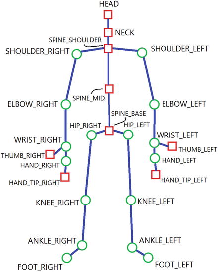
Figure 5-1. The various joints represented in the Kinect for Windows v2 API. Square joints represent joints that have been altered from or were unavailable in the v1 SDK.
The process of grabbing body frames is a bit different than that for the more visual frames. There is a special BodyFrame method called GetAndRefreshBodyData (IList<Body> bodies) that we have to call in every FrameArrived event handler call in order to get our body data. To reduce memory consumption, the SDK directly updates the necessary parts of the Body array that is inputted into this method. This array should be maintained throughout the lifetime of the BodyFrameReader’s operation.
Drawing Skeletons
The quintessential demonstration of the Kinect’s skeletal-tracking abilities has always been the superimposition of a stick figure or dots representing the joints and bones of a tracked user on a video feed. It can be amusing to watch people unfamiliar with the Kinect prance around trying to see if the Kinect can keep up through its body tracking. They are always quite surprised to see their skeletal reflections rendered onto a screen in real-time, never mind that a comparatively low-tech solution, putting stickers on yourself and looking at a mirror, can yield much better results. There is something about computers slowly but surely adopting human-like perception that is entertaining to watch.
Drawing Joints
We will get started with a simple dots-for-joints demonstration. We will draw purple dots on the color camera feed for the location of tracked joints and gray dots for the location of inferred joints, which are joints that the Kinect cannot see at the moment but assumes are present. Start a new C# WPF project and include the standard assortment of namespaces: System, System.Collections.Generic, System.Linq, System.Windows, System.Windows.Media, System.Windows.Media.Imaging, and Microsoft Kinect. Some extra namespaces that also need to be included this time around are System.Windows.Shapes and System.Windows.Controls so that we can draw joints as circles on a Canvas control.
Listing 5-1. MainWindow.xaml.cs Private Variable Declaration for Displaying Skeletal Joints
public partial class MainWindow : Window{private KinectSensor kinect;private MultiSourceFrameReader multiSourceFrameReader;//private BodyFrameReader bodyFrameReader;private CoordinateMapper coordinateMapper;FrameDescription colorFrameDescription;private WriteableBitmap colorBitmap;private bool dataReceived;private Body[] bodies;...}
In Listing 5-1, we opted to create a MultiSourceFrameReader instead of a BodyFrameReader. This will allow us to read frames from multiple Data Sources relatively synchronously without having to open multiple readers. You should keep in mind that there is no Data Source called MultiFrameSource. It is mostly an abstraction of convenience, and we could have called the readers for the color and skeletal Data Sources individually instead.
By this point in the book, you might be wondering about how the depth camera and color camera have different images that by default do not align. Quite simply, if you look at the front of your Kinect, the cameras are not in the same spot, not to mention have different resolutions. As a consequence, we have to align the images. We can do this mathematically, but fortunately the Kinect has already done this for us. In Listing 5-1, we declare an instance of the CoordinateMapper utility class to let us align points in both images along with the positions of skeletal joints. It is not a static class and is a property of each individual KinectSensor object.
Culminating the private variables, we have the dataReceived boolean, which will toggle whether we draw our joints based on the availability of new data, and the bodies array, which will hold the skeletal data collected by the Kinect.
Listing 5-2. MainWindow.xaml.cs Constructor and Variable Assignment for Displaying Skeletal Joints
public MainWindow(){kinect = KinectSensor.GetDefault();multiSourceFrameReader = kinect.OpenMultiSourceFrameReader(FrameSourceTypes.Color | FrameSourceTypes.Body);multiSourceFrameReader.MultiSourceFrameArrived += MultiSourceFrameReader_MultiSourceFrameArrived;coordinateMapper = kinect.CoordinateMapper;colorFrameDescription = kinect.ColorFrameSource.CreateFrameDescription(ColorImageFormat.Bgra);colorBitmap = new WriteableBitmap(colorFrameDescription.Width, colorFrameDescription.Height, 96.0, 96.0, PixelFormats.Bgra32, null);kinect.Open();DataContext = this;InitializeComponent();}public ImageSource ImageSource{get{return colorBitmap;}}
In Listing 5-2, we initialize our reader and the other variables necessary for skeletal tracking. Note that the method signature for creating MultiSourceFrameReaders is different from that for the other Data Sources. Instead of calling KinectSensor.XFrameSource.OpenReader() as with the others, we called the KinectSensor’s OpenMultiSourceFrameReader(FrameSourceTypes enabledFrameSourceTypes) method. As mentioned previously, there is no MultiFrameSource Data Source property in the KinectSensor object to access directly. FrameSourceTypes indicates which Data Sources we want our reader to offer frames from. It is an enum that can be delineated by the overloaded | operator (which acts as a bitmask). Like the other readers, we can assign it event handlers to be triggered when frames arrive. We also assign CoordinateMapper and WriteableBitmap in the constructor.
Listing 5-3. MainWindow.xaml.cs Event Handler for Displaying Skeletal Joints
private void MultiSourceFrameReader_MultiSourceFrameArrived(object sender, MultiSourceFrameArrivedEventArgs e){bool dataReceived = false;MultiSourceFrame multiSourceFrame = e.FrameReference.AcquireFrame();using (ColorFrame colorFrame = multiSourceFrame.ColorFrameReference.AcquireFrame()){if (colorFrame != null){using (KinectBuffer colorBuffer = colorFrame.LockRawImageBuffer()){colorBitmap.Lock();if ((colorFrameDescription.Width == colorBitmap.PixelWidth) && (colorFrameDescription.Height == colorBitmap.PixelHeight)){colorFrame.CopyConvertedFrameDataToIntPtr(colorBitmap.BackBuffer,(uint)(colorFrameDescription.Width * colorFrameDescription.Height * 4),ColorImageFormat.Bgra);colorBitmap.AddDirtyRect(new Int32Rect(0, 0, colorBitmap.PixelWidth, colorBitmap.PixelHeight));}colorBitmap.Unlock();}}}using (BodyFrame bodyFrame = multiSourceFrame.BodyFrameReference.AcquireFrame()){if (bodyFrame != null){if (bodies == null){bodies = new Body[bodyFrame.BodyCount];}bodyFrame.GetAndRefreshBodyData(bodies);dataReceived = true;}}if (dataReceived){canvas.Children.Clear();foreach (Body body in bodies.Where(b => b.IsTracked)){foreach (var joint in body.Joints){CameraSpacePoint position = joint.Value.Position;if (position.Z < 0){position.Z = 0.1f;}ColorSpacePoint colorSpacePoint = coordinateMapper.MapCameraPointToColorSpace(position);if (joint.Value.TrackingState == TrackingState.Tracked){DrawJoint(new Point(colorSpacePoint.X, colorSpacePoint.Y), new SolidColorBrush(Colors.Purple));}if (joint.Value.TrackingState == TrackingState.Inferred){DrawJoint(new Point(colorSpacePoint.X, colorSpacePoint.Y), new SolidColorBrush(Colors.LightGray));}}}}}
In Listing 5-3, we have a large event handler method that encapsulates the code for both displaying color images and grabbing skeletal frames. In a larger application, we would probably split this up by passing the MultiSourceFrameArrivedEventArgs e or the frames to separate methods. For simplicity’s sake, I put them together here. It is noteworthy that there is a bit of Inception going on with the frame references for MultiSourceFrames. With the other Data Sources, the process of grabbing data can be summated with xFrameArrivedEventArgs ➤ xFrameReference ➤ xFrame ➤ Underlying Data Buffer. With multi-source data, the process is MultiSourceFrameEventArgs ➤ MultiSourceFrameReference ➤ MultiSourceFrame ➤ xFrameReference ➤ xFrame ➤ Underlying Data Buffer. The important thing to know is that the MultiSourceFrames contain the references for the other frames, and the rest of the paradigm works as you would expect.
There is nothing interesting about our code to acquire and present color data; it is the same as in Chapter 3. In the using (BodyFrame ...) portion of the code, we create a new array of bodies if none exists and then update it with the bodyFrame.GetAndRefreshBodyData(bodies) statement. We set the dataReceived flag to true so that we know to execute the joint-drawing portion of the code. This is reset to false every time the event handler is called.
We could have chosen to draw the joints directly onto the Image WPF control, writing over the relevant color pixels in our colorBitmap, but instead we will draw the joints on a Canvas control that will be overlaid on top of our color image. This is mainly a matter of preference, though there are some trade-offs. For example, if we wanted to take a screenshot, we would not be able to use the code from Chapter 3 to do so if we were using the Canvas control. We would instead have to rely on the RenderTargetToBitmap class to take a snapshot of the Image and Canvas controls simultaneously. We opted for Canvas out of convenience.
We start off the drawing portion of our code by calling canvas.Children.Clear(), which deletes all the existing joint dots on the canvas. These were created as child WPF controls of our Canvas (called canvas).
Reminder
WPF controls are simply the XAML UI elements with which we design the front end of our application. Think of them as HTML tags, such as <Button />.
Using LINQ, we loop through each body in our bodies array that is being tracked to apply our drawing code. The Joints property of Body contains a dictionary of key-value pairs for each joint in the tracked body. If we wanted to access a specific joint directly, we could query the JointType in the dictionary as such:
Joint j = joints[JointType.ElbowRight];Note that the identifiers for the JointTypes are all written as camel-cased renditions of those listed in Figure 2-1 (i.e., Elbow_Right is written as ElbowRight in this context).
Tip
LINQ, or Language Integrated Query, is a .NET component that allows us to make queries on lists, arrays, and other data structures. It has statements such as Select or Where that help us map, filter, extract, and process data to get the interesting bits. It helps us eliminate superfluous loops and if statements. It has even been ported to other languages such as Java. To learn more, visit https://msdn.microsoft.com/en-us/library/mt693024.aspx .
Looping through the joints, we start off by extracting the Position property of each joint as seen from the Depth camera, which is defined as a CameraSpacePoint. Next, we clamp its depth value (position.Z), ensuring that it is above 0, to prevent the CoordinateMapper from returning negative infinity values when we convert it to a ColorSpacePoint. These depth values can be negative as a result of algorithms used by the Kinect SDK to determine the position of inferred joints. It might seem odd that the depth value is relevant at all in the conversion from a 3D coordinate system to a 2D coordinate system, but it makes sense. If you think about it, the smaller the distance between the camera and a person, the larger their skeleton (and their joints) should appear on the screen. Thus, the relationship between the depth value and the size of the joints in the color space is inversely proportional.
Tip
CameraSpacePoints are one of the three types of coordinate space points in the Kinect 2 SDK. It refers to the 3D coordinate system used by the Kinect. Its origin is located at the center of the depth camera, and each unit of measure is equivalent to one meter. ColorSpacePoint marks the location of coordinates on a 2D color image (as garnered from a ColorFrame). Likewise, DepthSpacePoint marks the location of coordinates on a 2D depth image.
After the depth value is clamped, we need to convert the depth positions to the color camera view positions. Thus, we call the MapCameraPointToColorSpace(CameraSpacePoint cameraPoint) method of CoordinateMapper to find the location of the joint on our color image. Checking the TrackingState property of each joint, we determine whether to color it purple for Tracked or light gray for Inferred. We give the coordinates of the ColorSpacePoint as a Point object to our custom DrawJoint(Point jointCoord, SolidColorBrush s) method, along with the desired color of the joint on the canvas.
Listing 5-4. MainWindow.xaml.cs Drawing Method for Displaying Skeletal Joints
private void DrawJoint(Point jointCoord, SolidColorBrush s){if (jointCoord.X < 0 || jointCoord.Y < 0)return;Ellipse ellipse = new Ellipse(){Width = 10,Height = 10,Fill = s};Canvas.SetLeft(ellipse, (jointCoord.X/colorFrameDescription.Width) * canvas.ActualWidth - ellipse.Width / 2);Canvas.SetTop(ellipse, (jointCoord.Y/colorFrameDescription.Height) * canvas.ActualHeight - ellipse.Height / 2);canvas.Children.Add(ellipse);}
In Listing 5-4, we have the method that is responsible for drawing the joints on our canvas. We first confirm that the joint coordinates on the color image have positive values. We create a new ellipse object for the joint and give it a 10-pixel diameter and our chosen brush as the fill color. We then set the x coordinate and y coordinate of the ellipse on the Canvas with the Canvas class’ SetLeft(UIElement element, double length) and SetTop(UIElement element, double length) methods, respectively. The (0, 0) coordinate for the Canvas is the top-left pixel, as with images. There is an interesting bit of calculating we must do to determine where we put the circle on the Canvas:
Canvas.SetLeft(ellipse, (jointCoord.X/colorFrameDescription.Width) * canvas.ActualWidth - ellipse.Width / 2);The preceding calculation also applies for the y coordinate. Normally, ColorSpacePoints refer to Cartesian coordinates on the color camera image. This image is normally 1920 x 1080 pixels, but for whatever reason, it might be displayed in a different resolution. In our case, we set the image to 1024 x 576 in our application so that it can fit better in our monitor. Thus, we must scale down the coordinate value so that it fits in this lower-resolution image. In the example of the x coordinate, we divide its value by the width of the original image and then multiply it by the width of our Canvas. SetLeft(...) and SetTop(...) set elements on the canvas by their top-left corners, so we subtract the radius of the ellipse from the length to ensure it is set to the desired location by its center.
Listing 5-5. MainWindow.xaml Front End for Displaying Skeletal Joints
<Window [...]Title="Skeletal Joints" Height="604" Width="1028" ResizeMode="NoResize"><Grid><Image Source="{Binding ImageSource}" Width="1024" Height="576" /><Canvas Name="canvas" Width="1024" Height="576" /></Grid></Window>
In the front end (Listing 5-5), we add the Canvas element right after the Image element so that it is displayed in front of the image and not behind. The rest of the XAML is otherwise uninteresting. Compile and run the application, then stand a short distance away from the Kinect. If you can see the joint dots on your screen like as in Figure 5-2, then you can try sitting down or appearing in other positions to see that it is working as anticipated.
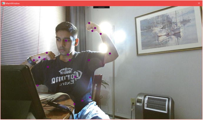
Figure 5-2. Skeletal joints displayed on a user. Notice the light gray dots under the waist, which represent the inferred positions of the leg joints. The torso and waist joints are being partially shifted as a result of the table’s obstructing the lower right side of the user’s abdomen.
Note
Are your joint dots flashing erratically and ruining your aesthetic? This is happening because we are calling the canvas.Children.Clear() method several times per second, thus causing all the dots to disappear on the screen for brief instants before they are redrawn. To mitigate this issue, you can keep track of all the canvas joint ellipses with a data structure and then loop through them in each frame, changing their locations on the canvas systematically instead of clearing them. Alternatively, you can draw on the image directly with the use of the DrawingContext class. Refer to the BodyBasics-WPF sample to see how. The exact implementation of the solution is left to the reader as an exercise.
Drawing Bones
There is no concept of “bones” in the Kinect SDK. We have to enumerate the various connections between the provided joints ourselves before we draw them. The process of drawing them is similar to doing so for the joints. The primary difference is that instead of drawing ellipses, we will be drawing lines.
Listing 5-6. MainWindow.xaml.cs Additional Private Variables to Display Skeletons
...private Body[] bodies; //previously declared private variablesprivate List<Tuple<JointType, JointType>> bones;private List<SolidColorBrush> bodyColors;...
In Listing 5-6, we make a list of tuples to represent the various joint relationships in the body that constitute bones. Additionally, we make a list for the colors we will use to paint each body.
Listing 5-7. MainWindow.xaml.cs Additional Constructor Code to Display Skeletons
public MainWindow(){bones = new List<Tuple<JointType, JointType>>();//Torsobones.Add(new Tuple<JointType, JointType>(JointType.Head, JointType.Neck));bones.Add(new Tuple<JointType, JointType>(JointType.Neck, JointType.SpineShoulder));bones.Add(new Tuple<JointType, JointType>(JointType.SpineShoulder, JointType.SpineMid));bones.Add(new Tuple<JointType, JointType>(JointType.SpineMid, JointType.SpineBase));bones.Add(new Tuple<JointType, JointType>(JointType.SpineShoulder, JointType.ShoulderRight));bones.Add(new Tuple<JointType, JointType>(JointType.SpineShoulder, JointType.ShoulderLeft));bones.Add(new Tuple<JointType, JointType>(JointType.SpineBase, JointType.HipRight));bones.Add(new Tuple<JointType, JointType>(JointType.SpineBase, JointType.HipLeft));//Left Armbones.Add(new Tuple<JointType, JointType>(JointType.ShoulderLeft, JointType.ElbowLeft));bones.Add(new Tuple<JointType, JointType>(JointType.ElbowLeft, JointType.WristLeft));bones.Add(new Tuple<JointType, JointType>(JointType.WristLeft, JointType.HandLeft));bones.Add(new Tuple<JointType, JointType>(JointType.HandLeft, JointType.HandTipLeft));bones.Add(new Tuple<JointType, JointType>(JointType.WristLeft, JointType.ThumbLeft));//Right Armbones.Add(new Tuple<JointType, JointType>(JointType.ShoulderRight, JointType.ElbowRight));bones.Add(new Tuple<JointType, JointType>(JointType.ElbowRight, JointType.WristRight));bones.Add(new Tuple<JointType, JointType>(JointType.WristRight, JointType.HandRight));bones.Add(new Tuple<JointType, JointType>(JointType.HandRight, JointType.HandTipRight));bones.Add(new Tuple<JointType, JointType>(JointType.WristRight, JointType.ThumbRight));//Left Legbones.Add(new Tuple<JointType, JointType>(JointType.HipLeft, JointType.KneeLeft));bones.Add(new Tuple<JointType, JointType>(JointType.KneeLeft, JointType.AnkleLeft));bones.Add(new Tuple<JointType, JointType>(JointType.AnkleLeft, JointType.FootLeft));//Right Legbones.Add(new Tuple<JointType, JointType>(JointType.HipRight, JointType.KneeRight));bones.Add(new Tuple<JointType, JointType>(JointType.KneeRight, JointType.AnkleRight));bones.Add(new Tuple<JointType, JointType>(JointType.AnkleRight, JointType.FootRight));bodyColors = new List<SolidColorBrush>();bodyColors.Add(new SolidColorBrush(Colors.Red));bodyColors.Add(new SolidColorBrush(Colors.Green));bodyColors.Add(new SolidColorBrush(Colors.Orange));bodyColors.Add(new SolidColorBrush(Colors.Blue));bodyColors.Add(new SolidColorBrush(Colors.Yellow));bodyColors.Add(new SolidColorBrush(Colors.Pink));//remaining code in constructorkinect = KinectSensor.GetDefault();...
In the MainWindow constructor shown in Listing 5-7, we add a bunch of “bones” to the list, which are supposed to be reasonable-looking connections between the body joints that the SDK gives us access to. Like the joints, they do not necessarily depict our anatomy exactly as in a textbook, but instead have some abstractions applied to facilitate working with them through software. For example, there are two bones between our wrist and elbow joint, the radius and the ulna, but in our demonstration code we have only one bone, described as Tuple<JointType, JointType>(JointType.ElbowLeft, JointType.WristLeft). In addition to the bones, we add six colors to the bodyColors list for the six different skeletons.
Listing 5-8. MainWindow.xaml.cs Modified FrameArrived Event Handler
...//color and body frames grabbed and processed before thisif (dataReceived){canvas.Children.Clear();//Add this lineint colorIndex = 0;foreach (Body body in bodies.Where(b => b.IsTracked)){//Add the following linesSolidColorBrush colorBrush = bodyColors[colorIndex++];Dictionary<JointType, Point> jointColorPoints = new Dictionary<JointType, Point>();foreach (var joint in body.Joints){//[...] depth clamping omitted for brevityColorSpacePoint colorSpacePoint = coordinateMapper.MapCameraPointToColorSpace(position);//Add this linejointColorPoints[joint.Key] = new Point(colorSpacePoint.X, colorSpacePoint.Y);//[...] DrawJoint calls omitted for brevity}//Add this foreach loopforeach (var bone in bones){DrawBone(body.Joints, jointColorPoints, bone.Item1, bone.Item2, colorBrush);}}}
Listing 5-8 contains the skeleton- and joint-drawing portions of the MultiSourceFrameReader_MultiSourceFrameArrived event handler. We keep track of body colors with colorIndex so that we can maintain a unique color for each body in the frame with the SolidColorBrush colorBrush = bodyColors[colorIndex++]; statement. A dictionary is created to keep track of the ColorSpacePoints being mapped for each joint in the body. Once we have this data, we loop through all the joint-joint tuples in our bones list and draw them. We have a new DrawBone(...) method for this; we will not be modifying the DrawJoint(...) method from earlier, which is still needed for the joints.
Listing 5-9. MainWindow.xaml.cs Drawing Method for Bones
private void DrawBone(IReadOnlyDictionary<JointType, Joint> joints, IDictionary<JointType, Point> jointColorPoints, JointType jointType0, JointType jointType1, SolidColorBrush color){Joint joint0 = joints[jointType0];Joint joint1 = joints[jointType1];if (joint0.TrackingState == TrackingState.NotTracked || joint1.TrackingState == TrackingState.NotTracked)return;if (jointColorPoints[jointType0].X < 0 || jointColorPoints[jointType0].Y < 0 || jointColorPoints[jointType1].X < 0 || jointColorPoints[jointType0].Y < 0)return;Line line = new Line(){X1 = (jointColorPoints[jointType0].X / colorFrameDescription.Width) * canvas.ActualWidth,Y1 = (jointColorPoints[jointType0].Y / colorFrameDescription.Height) * canvas.ActualHeight,X2 = (jointColorPoints[jointType1].X / colorFrameDescription.Width) * canvas.ActualWidth,Y2 = (jointColorPoints[jointType1].Y / colorFrameDescription.Height) * canvas.ActualHeight,StrokeThickness = 5,Stroke = color};canvas.Children.Add(line);}
In the DrawBone(...) method featured in Listing 5-9, we begin by refusing to draw any bones for situations where the necessary data is not present. This is namely when any of the joints are not tracked, or when their color-image coordinates are not positive values. Next, we create a line with the coordinates of the joints as its start and end points, along with the desired color inputted from bodyColor[colorIndex++]. Notice that the joint coordinates fed into the line are scaled as we did with the joints. Finally, we added the line to the canvas. Compiling the application should result in a scene like that in Figure 5-3.
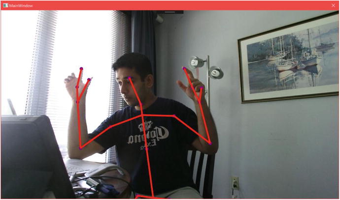
Figure 5-3. Skeleton displayed on a user
Showing Clipped Edges
More often than not, users will not fully position their body within the view range of the Kinect. The Kinect SDK has an easy way for us to find out if such is the case. Each Body object has a ClippedEdge property that tells us on which edges of the image the user’s skeleton is being clipped on. This can be useful in many ways, such as knowing when to tell the user to move back into the Kinect’s view range, as in Figure 5-4.
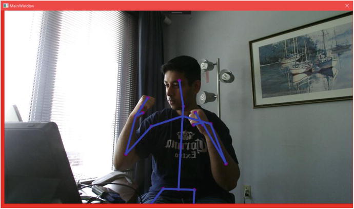
Figure 5-4. Clipped edges shown as red lines on the sides. The left edge is being shown as clipped because the person’s right leg joints are inferred as being past that edge on the frame .
Drawing clipped edges in our existing application only requires minor edits. We will include a method to draw lines on the sides of the image representing the clipped edges and call it from the event handler for MultiSourceFrame.
Listing 5-10. MainWindow.xaml.cs Method for Drawing Clipped Edges
private void DrawClippedEdges(Body body){FrameEdges clippedEdges = body.ClippedEdges;if (clippedEdges.HasFlag(FrameEdges.Bottom)){Line edge = new Line(){X1 = 0,Y1 = canvas.ActualHeight - 9,X2 = canvas.ActualWidth,Y2 = canvas.ActualHeight - 9,StrokeThickness = 20,Stroke = new SolidColorBrush(Colors.Red)};canvas.Children.Add(edge);}if (clippedEdges.HasFlag(FrameEdges.Top)){Line edge = new Line(){X1 = 0,Y1 = 0,X2 = canvas.ActualWidth,Y2 = 0,StrokeThickness = 20,Stroke = new SolidColorBrush(Colors.Red)};canvas.Children.Add(edge);}if (clippedEdges.HasFlag(FrameEdges.Left)){Line edge = new Line(){X1 = 0,Y1 = 0,X2 = 0,Y2 = canvas.ActualHeight,StrokeThickness = 20,Stroke = new SolidColorBrush(Colors.Red)};canvas.Children.Add(edge);}if (clippedEdges.HasFlag(FrameEdges.Right)){Line edge = new Line(){X1 = canvas.ActualWidth - 9,Y1 = 0,X2 = canvas.ActualWidth - 9,Y2 = canvas.ActualHeight,StrokeThickness = 20,Stroke = new SolidColorBrush(Colors.Red)};canvas.Children.Add(edge);}}
In Listing 5-10, we can see that checking whether an edge is clipped is a matter of checking which FrameEdges are in body.ClippedEdges. Once we have this, we can draw a line on the canvas for each flagged frame edge. Finally, the DrawClippedEdges(Body body) method needs to be called in the loop in which we go through all the bodies and draw their joints and bones, as follows:
foreach (Body body in bodies.Where(b => b.IsTracked)){//[...] Rest of code to gather and draw jointsforeach (var bone in bones){DrawBone(body.Joints, jointColorPoints, bone.Item1, bone.Item2, colorBrush);}//Add this line to call DrawClippedEdgesDrawClippedEdges(body);}
Showing Hand States
While the Kinect supports more advanced gesture-recognition capabilities, being able to near-instantaneously determine whether the hands are clenched (closed), open, or in a lasso state is very convenient for smaller projects where we do not want to spend time defining custom gestures.
As with the clipped edges, showing hand states will not require a significant alteration of our existing application. We will add a method to paint a circle around the hand depending on the hand state. We will have Red represent a closed first, Green an open one, and Blue for one in the lasso form.
Listing 5-11. MainWindow.xaml.cs Method to Show Hand State with Colored Circles
private void DrawHandStates(HandState handState, Point handCoord){switch (handState){case HandState.Closed:Ellipse closedEllipse = new Ellipse(){Width = 100,Height = 100,Fill = new SolidColorBrush(Color.FromArgb(128, 255, 0, 0))};Canvas.SetLeft(closedEllipse, (handCoord.X / colorFrameDescription.Width) * canvas.ActualWidth - closedEllipse.Width / 2);Canvas.SetTop(closedEllipse, (handCoord.Y / colorFrameDescription.Height) * canvas.ActualHeight - closedEllipse.Width / 2);canvas.Children.Add(closedEllipse);break;case HandState.Open:Ellipse openEllipse = new Ellipse(){Width = 100,Height = 100,Fill = new SolidColorBrush(Color.FromArgb(128, 0, 255, 0))};Canvas.SetLeft(openEllipse, (handCoord.X / colorFrameDescription.Width) * canvas.ActualWidth - openEllipse.Width / 2);Canvas.SetTop(openEllipse, (handCoord.Y / colorFrameDescription.Height) * canvas.ActualHeight - openEllipse.Width / 2);canvas.Children.Add(openEllipse);break;case HandState.Lasso:Ellipse lassoEllipse = new Ellipse(){Width = 100,Height = 100,Fill = new SolidColorBrush(Color.FromArgb(128, 0, 0, 255))};Canvas.SetLeft(lassoEllipse, (handCoord.X / colorFrameDescription.Width) * canvas.ActualWidth - lassoEllipse.Width / 2);Canvas.SetTop(lassoEllipse, (handCoord.Y / colorFrameDescription.Height) * canvas.ActualHeight - lassoEllipse.Width / 2);canvas.Children.Add(lassoEllipse);break;}}
In Listing 5-11, we see the method that is used to paint circles representing hand states onto the canvas. HandState is an enum with five possible values, the aforementioned Open, Closed, and Lasso, as well as Unknown and NotTracked. The switch-case statement finds out what state the hand is in and then basically draws the circle in a manner similar to the DrawJoint method using the ColorSpacePoint coordinates of the hand. The method is called twice per hand, as follows:
...//[...] Rest of code to gather and draw joints and bonesDrawClippedEdges(body);//Add these lines to MultiSourceFrameReader_MultiSourceFrameArrivedDrawHandStates(body.HandRightState, jointColorPoints[JointType.HandRight]);DrawHandStates(body.HandLeftState, jointColorPoints[JointType.HandLeft]);...
This method is called in the MultiSourceFrame event handler right after (or before) the DrawClippedEdges(Body body) method. The HandState enumeration can be obtained from the HandRightState and HandLeftState properties of Body. The color space coordinates of the joints that we derived earlier are used here to tell the method where to draw the hand-state circles. Compiling and running the application at this point should result in a scene similar to that in Figure 5-5.
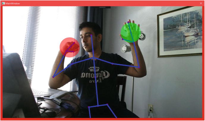
Figure 5-5. Hand states depicted with colored circles
It is worth knowing that Body has HandLeftConfidence and HandRightConfidence properties that return a TrackingConfidence value for the left and right hand states, respectively. TrackingConfidence is nothing but an enum with two values, High and Low, whose meanings are self-described.
Understanding Joint Orientations
In the “Drawing Skeletons” section, we saw how CameraSpacePoint coordinates could be used to reconstruct a user’s skeleton. There is an alternative way to achieve this, which is through joint orientations. Joint orientation can be one of the more difficult concepts to grasp in the Kinect SDK, but is especially useful in applications such as avateering, where the proportions of an animated character might not correspond to a user’s actual body. Just think of the calamity that would ensue if we tried to rig a LeBron James model in a Kinect basketball game with the joint coordinates of an eight-year-old kid! Each playable athlete in the game would have different arm and leg proportions, and they would all be different from the wide range of possible users playing the game. Or think about if we tried to avateer a T-Rex, which are notorious for their short, stubby arms. It’s easy to see how absolute metric coordinates are not as helpful in such cases.
Joint orientations sidestep this issue by ignoring bone length and instead permitting us to rebuild the skeleton with knowledge of the joints’ local quaternion orientation values. These quaternion values indicate the rotation of a joint about the bone originating from its parent joint. Each joint has its place in a hierarchy, as depicted in Figure 5-6, which can be traversed to reconstruct a skeleton.

Figure 5-6. Joint hierarchy in the Kinect v2 SDK
Tip
Rotations in 3D-coordinate systems are often described with either Euler angles or quaternions. There are trade-offs to choosing either; Euler angles are conceptually simpler to understand, whereas quaternions avoid a critical issue with Euler angles known as gimbal lock and provide better results for certain computational operations. Typically, your graphical programming environment, whether it be something closer to metal such as DirectX or a full-fledged game engine such as Unity, will have utilities to abstract the complexities of working in between both. A more thorough discussion of how to work with both rotational description systems falls outside the purview of this book and could easily take up a few college lectures. A brief but succinct tutorial on rotations can be found at http://www.opengl-tutorial.org/intermediate-tutorials/tutorial-17-quaternions/ .
Normally, I would prefer to build a sample from scratch for us to explore, but considering the amount of code necessary to get a project working, we will inspect the excellent Kinect Evolution sample instead. We tinkered with it a bit in Chapter 1, but now we will go more in depth, specifically with its “Block(wo)man” demo (Figure 5-7). This is the one time that we will touch C++ in this book, but it will be brief and relatively painless. To find the sample, go to the SDK Browser v2.0 and select Install from Web for the Kinect Evolution-XAML entry. Navigate to the folder you installed it in and open the solution file.

Figure 5-7. The Block(wo)man demo in the Kinect Evolution sample
The code to get the whole avatar fleshed out in DirectX is somewhat involved, so we will focus on a top-level overview of the code that extracts and processes joint orientations. This portion is found in BlockManPanel.cpp, which is situated in the KinectEvolution.Xaml.Controls project within the solution.
Listing 5-12. BlockManPanel.cpp OnBodyFrame Method Part 1: Obtaining Joint Orientations
[...]//Body was obtained from body frame before this pointIMapView<JointType, Joint>^ joints = body->Joints;IMapView<JointType, JointOrientation>^ jointOrientations = body->JointOrientations;{for (UINT i = 0; i < joints->Size; i++){JointType jt = static_cast<JointType>(i);//this bit is unimportantif (jt == JointType::Head){continue;}JointOrientation jo = jointOrientations->Lookup(jt);_blockMen[iBody]._JointOrientations[i] = SmoothQuaternion(_blockMen[iBody]._JointOrientations[i], XMLoadFloat4((XMFLOAT4*) &jo.Orientation));}...
In Listing 5-12, we have the code right after the start of the OnBodyFrame(_In_ BodyFrame^ bodyFrame) event handler, which is the C++ equivalent of an event handler for BodyFrameReader’s FrameArrived event in C#. The body was already obtained, and now we proceed to extract the joints and joint orientations. We then apply a function to each joint orientation, SmoothQuaternion(...), that, in short, normalizes the quaternion and interpolates between its prior and new states using spherical linear interpolation. Do not worry if that bit made no sense. The point is to smooth the motion of the quaternion between frames to reduce noise and jerkiness. SmoothQuaternion(...) is made up of DirectX quaternion helper methods.
Listing 5-13. BlockManPanel.cpp OnBodyFrame Method Part 2: Inspecting Skeleton Blocks
...for (int blockIndex = 0; blockIndex < BLOCK_COUNT; ++blockIndex){JointType jointIndex = g_SkeletonBlocks[blockIndex].SkeletonJoint;int parentIndex = g_SkeletonBlocks[blockIndex].ParentBlockIndex;XMVECTOR translateFromParent = g_SkeletonBlocks[blockIndex].CenterFromParentCenter;XMMATRIX parentTransform = (parentIndex > -1) ? _blockMen[iBody]._BlockTransforms[parentIndex] : XMMatrixIdentity();XMVECTOR position = XMVector3Transform(translateFromParent, parentTransform);...
In the header file, BlockManPanel.h, we defined a SkeletonBlock structure for each joint pair that is used by DirectX to construct the 3D blocks used to make our Block(wo)man. In Listing 5-13, we are simply calculating each SkeletonBlock’s position and base rotation based off its parent SkeletonBlock’s properties.
Listing 5-14. BlockManPanel.cpp OnBodyFrame Method Part 3: Determining Joint Rotation
...XMVECTOR rotationQuat = XMVectorZero();if (XMVector4Equal(_blockMen[iBody]._JointOrientations[(int)jointIndex], XMVectorZero())){if (parentIndex > -1){if (XMVector4Equal(_blockMen[iBody]._JointOrientations[parentIndex], XMVectorZero())){rotationQuat = XMQuaternionIdentity();}else{rotationQuat = _blockMen[iBody]._JointOrientations[parentIndex];}}}else{rotationQuat = _blockMen[iBody]._JointOrientations[(int) jointIndex];}...
In Listing 5-14, we get the rotation quaternions from the joints based off their orientation. In certain cases, the joint’s orientation is not available, so we use the parent joint’s orientation. If this is not available, we assume no further orientation.
Listing 5-15. BlockManPanel.cpp OnBodyFrame Method Part 4: Creating Model Matrix
...XMMATRIX translation = XMMatrixTranslationFromVector(position);XMMATRIX scale = XMMatrixScalingFromVector(g_SkeletonBlocks[blockIndex].Scale);XMMATRIX rotation = XMMatrixRotationQuaternion(rotationQuat);_blockMen[iBody]._BlockTransforms[blockIndex] = scale * rotation * translation;}Joint joint = joints->Lookup(JointType::SpineBase);_blockMen[iBody]._position = XMLoadFloat4((XMFLOAT4*) &(joint.Position));}
In Listing 5-15, we bring everything together and calculate the translation, scale, and rotation matrices for the SkeletonBlock. These are multiplied by each other to determine the SkeletonBlock’s overall transformation matrix, which will essentially decide how the block will appear on screen. At the completion of the iteration through the SkeletonBlocks, we set the SpineBase’s position as the position of the skeleton, as it is the root joint of the joint hierarchy .
The important thing to remember throughout is that the orientation of a joint is based off its parent joint’s orientation. If a body’s thumb joint rotates by 20 degrees on a certain axis, it is not rotating 20 degrees from the global Cartesian space, but rather 20 degrees from the hand joint.
Determining Body Lean
The Kinect SDK has a convenient way to determine whether a user is leaning or not. This capability is limited and does not provide us with the exact characteristics of the lean, such as its angular direction or how pronounced it is, but it is still useful if you only need to know roughly whether a person is leaning forward or backward and/or right or left. This can be a quick way to implement a “dodge” feature in a game so that the player can avoid projectiles, or a way to see if the user is engaged (i.e., leaning forward).
Determining the lean value is simply a matter of accessing the Lean property of Body (Listing 5-16).
Listing 5-16. Determining the Lean Value of a Body
foreach (Body body in bodies.Where(b => b.IsTracked)){PointF lean = body.Lean;float xLean = lean.X;float yLean = lean.Y;DrawLean(xLean, yLean, body.LeanTrackingState);[...]}private void DrawLean(float xLean, float yLean, TrackingState leanTrackingState){var drawLean = false;//The following shows the different lean statesswitch (leanTrackingState){case TrackingState.Inferred://Do nothingbreak;case TrackingState.NotTracked://Do nothingbreak;case TrackingState.Tracked:drawLean = true;break;}//We'll only draw this if the user leaning state is trackedif (drawLean){//Draw a Left/Right Lean Meter at top of screenRectangle mainHorizontalMeter = new Rectangle(){Width = canvas.ActualWidth - 50,Height = 50,Fill = new SolidColorBrush(Color.FromArgb(100, 128, 100, 200))};//Draw a Forward/Back Lean Meter at Right side of screenRectangle mainVerticalMeter = new Rectangle(){Width = 50,Height = canvas.ActualHeight - 50,Fill = new SolidColorBrush(Color.FromArgb(100, 50, 250, 250))};//Set Position and Add the meter to the drawing canvasCanvas.SetLeft(mainHorizontalMeter, 0);Canvas.SetTop(mainHorizontalMeter, 0);canvas.Children.Add(mainHorizontalMeter);//Set Position and Add the meter to the drawing canvasCanvas.SetLeft(mainVerticalMeter, canvas.ActualWidth - 60);Canvas.SetTop(mainVerticalMeter, 50);canvas.Children.Add(mainVerticalMeter);//Draw out measurement rectangleRectangle leftRightLean = new Rectangle(){Width = 10,Height = 38,Fill = new SolidColorBrush(Color.FromArgb(150, 0, 0, 0))};//Draw a Forward/Back Lean Meter at Right side of screenRectangle forwardBackLean = new Rectangle(){Width = 38,Height = 10,Fill = new SolidColorBrush(Color.FromArgb(150, 0, 0, 0))};//Figure out how much to draw based on xLean and yLean values//xLean and yLean are normalized between -1 and 1, so we will//use those values to be width values of our meter//0 ... 1 - 1/2 width to full width of meter//-1 ... 0 - 0 width to 1/2 width of metervar halfWidth = mainHorizontalMeter.Width/2;var horizontalMeter = ( (xLean > 0) ? xLean * (mainHorizontalMeter.Width ) : Math.Abs(xLean * (halfWidth)) );var halfHeight = mainVerticalMeter.Height/2;var verticalMeter =( (yLean > 0) ? yLean*(mainVerticalMeter.Height ): Math.Abs(yLean * (halfHeight)) ) + 50;if (xLean < 0){Canvas.SetLeft(leftRightLean, (canvas.ActualWidth / 2) - horizontalMeter);Canvas.SetTop(leftRightLean, 5);leftRightLean.Width = horizontalMeter;}else{Canvas.SetLeft(leftRightLean, (canvas.ActualWidth / 2));Canvas.SetTop(leftRightLean, 5);leftRightLean.Width = horizontalMeter;}canvas.Children.Add(leftRightLean);if (yLean > 0){Canvas.SetLeft(forwardBackLean, (canvas.ActualWidth - 55));Canvas.SetTop(forwardBackLean, halfHeight - verticalMeter);forwardBackLean.Height = verticalMeter;}else{Canvas.SetLeft(forwardBackLean, canvas.ActualWidth - 55);Canvas.SetTop(forwardBackLean, canvas.ActualHeight / 2);forwardBackLean.Height = verticalMeter;}canvas.Children.Add(forwardBackLean);//Now we'll add some simple text labels in the meterTextBlock labelLeft = new TextBlock() { Text="<< --- Leaning Left", FontSize=16.0, Foreground = new SolidColorBrush(Color.FromArgb(150, 0, 0, 0)) };Canvas.SetLeft(labelLeft, (canvas.ActualWidth *.25 ) );Canvas.SetTop(labelLeft, 10);canvas.Children.Add(labelLeft);TextBlock labelRight = new TextBlock() { Text = "Leaning Right --- >>>", FontSize = 16.0, Foreground = new SolidColorBrush(Color.FromArgb(150, 0, 0, 0)) };Canvas.SetLeft(labelRight, canvas.ActualWidth * .75 );Canvas.SetTop(labelRight, 10);canvas.Children.Add(labelRight);TextBlock labelForward = new TextBlock() { Text = "Forward", FontSize = 8.0, Foreground = new SolidColorBrush(Color.FromArgb(150, 0, 0, 0)) };Canvas.SetLeft(labelForward, canvas.ActualWidth - 55);Canvas.SetTop(labelForward, canvas.ActualHeight * .25);canvas.Children.Add(labelForward);TextBlock labelBackward = new TextBlock() { Text = "Backward", FontSize = 8.0, Foreground = new SolidColorBrush(Color.FromArgb(150, 0, 0, 0)) };Canvas.SetLeft(labelBackward, canvas.ActualWidth - 55);Canvas.SetTop(labelBackward, canvas.ActualHeight * .75);canvas.Children.Add(labelBackward);}}
The x and y values of lean are normalized values that refer to the confidence of the lean. The values range from −1 to 1, which is left to right on the x-axis and back to front on the y-axis, respectively. So, a lean value of x: −0.17, y: 0.94 would mean a possible but unlikely lean to the left and a probable lean forward.
As with hand states, there is a TrackingState property for lean called LeanTrackingState. This can be used to determine whether a body’s lean itself is being tracked.
BodyIndexFrameSource: Body Index Data
There are times when we need to determine whether a pixel in a depth or color image belongs to a player. We might want to draw an outline around a player to indicate that it is their turn, or we could cut out their body from the image and use it in a green screen application. BodyIndexFrameSource is the Data Source that enables us to do so. It lets us know whether pixels in a depth image are a part of a specific player or the background. Using CoordinateMapper, we can extract a player’s image from a color image as well.
Displaying BodyIndex Data
Working with BodyIndexFrameSource is very much like working with color, infrared, or depth data. It is an image from which we can copy, process, and present image data. It features the familiar CopyFrameDataToArray and CopyFrameDataToIntPtr methods, as well as LockImageBuffer. The resolution is naturally the same as that of the depth and infrared frames (as skeletal data is being processed internally using those frames), and each pixel is represented by an 8-bit unsigned integer. Each pixel in the array will have a value from 0 to 5 that corresponds to the index of the Body array provided by BodyFrameSource; a pixel with the value 2 represents a depth pixel occupied by the player found in bodies[2].
I will only show the FrameArrived event handler, as the rest of the code can be inferred from the color or depth image samples. If need be, the source code for the full application can be found in the book samples.
Listing 5-17. BodyIndexFrameReader Event Handler
private void Reader_BodyIndexFrameArrived(object sender, BodyIndexFrameArrivedEventArgs e){using (BodyIndexFrame bodyIndexFrame = e.FrameReference.AcquireFrame()){if (bodyIndexFrame != null){bodyIndexFrame.CopyFrameDataToArray(bodyIndexPixels);}for (int i = 0; i < bodyIndexPixels.Length; ++i){if (bodyIndexPixels[i] != 255){//player exists in space, draw their colorvar color = bodyIndexColors[bodyIndexPixels[i]];bitmapPixels[i * 4 + 0] = color.B;bitmapPixels[i * 4 + 1] = color.G;bitmapPixels[i * 4 + 2] = color.R;bitmapPixels[i * 4 + 3] = 255;}else{//no player found, write pixels as blackbitmapPixels[i * 4 + 0] = 0;bitmapPixels[i * 4 + 1] = 0;bitmapPixels[i * 4 + 2] = 0;bitmapPixels[i * 4 + 3] = 255;}}bodyIndexBitmap.WritePixels(new Int32Rect(0, 0,bodyIndexBitmap.PixelWidth,bodyIndexBitmap.PixelHeight),bitmapPixels,bodyIndexBitmap.PixelWidth * 4, 0);}}
In Listing 5-17, we transcribe the body index data from the BodyIndexFrame into the bodyIndexPixels byte array and then process its data for display in the bitmapPixels byte array, which represents RGBA data to be displayed through the bodyIndexBitmap WriteableBitmap. To make it clear which pixels are occupied by a player and which are not, we show an image that is black for the background and colored for any pixels with players in them. Going through each pixel of bodyIndexPixels, if it does not contain a player, it will have an unsigned integer value of 255, and thus we display an RGBA value of black for it. In cases where the value is not 255, we can assume that there is a player occupying the pixel. We have an array of six System.Windows.Media.Colors called bodyIndexColors, each of which coincides with a body the Kinect recognizes: the player index. We set its RGBA components as the corresponding four bytes in bitmapPixels. The result is then written to a WriteableBitmap to be used as an ImageSource.
In Figure 5-8, we have a screenshot of the application in operation. Two users are present in front of the Kinect. The general outlines of both can be clearly seen, but the edges are not well defined in certain areas. For the blue player, the bottom portion of one leg is obscured, so the Kinect attempts to resolve pixels near that leg through approximation, which is why there are blocky specks of blue. For the red player, the Kinect erroneously assumes that the area between the legs is part of the body. Errors like this are not uncommon, though overall the Kinect manages to do a decent job .
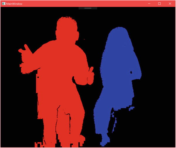
Figure 5-8. BodyIndex data displayed as an image
Rudimentary Green Screen App
The most evident use case for BodyIndexFrameSource is to create green screen apps with the Kinect. It is not real green-screening (otherwise known as Chroma-keying), as we are not subtracting the green color channel from the camera feed received by the Kinect. Instead, the Kinect is using machine-learning algorithms to find humans in the vicinity of the camera, and we can extract those directly. The final result is not as robust as what would have been obtained through Chroma-keying, but is a lot simpler to set up and has the added bonus of not removing any colors from the scene.
The process of extracting human images from the color feed is based off coordinate mapping the BodyIndexFrameSource data and keeping the corresponding pixels in the color feed while rendering the others transparent. We will inspect the event handler for the Data Sources directly without reviewing the variable declaration and constructor section of the app, as it features code we have gone over countless times before. As always, the full source code is included in the book samples.
Listing 5-18. MultiSourceFrameReader Event Handler for Green Screen Application Part 1
private void MultiSourceFrameReader_MultiSourceFrameArrived(object sender, MultiSourceFrameArrivedEventArgs e){System.Array.Clear(bitmapPixels, 0, bitmapPixels.Length);MultiSourceFrame multiSourceFrame = e.FrameReference.AcquireFrame();using (DepthFrame depthFrame = multiSourceFrame.DepthFrameReference.AcquireFrame()){if (depthFrame != null){depthFrame.CopyFrameDataToArray(depthPixels);coordinateMapper.MapDepthFrameToColorSpace(depthPixels, colorSpacePoints);}}using (BodyIndexFrame bodyIndexFrame = multiSourceFrame.BodyIndexFrameReference.AcquireFrame()){if (bodyIndexFrame != null){bodyIndexFrame.CopyFrameDataToArray(bodyIndexPixels);}}
In Listing 5-18, we have half of the MultiSourceFrameReader event handler for our green screen application. As expected, we make use of body index data, but what you might not have foreseen is that we need to use depth data too. Technically speaking, we do not need the depth data itself, but there is no built-in way to map body index coordinates to color space. Building our method to do so would not be tremendously difficult, but seeing as depth pixels correspond directly to body index pixels, we might as well rely on what already exists. In addition to grabbing depth and body index data, we also clear the bitmapPixels array. This is the array that holds the final processed color data to be displayed in the UI. We have to reset it each time, as we are not overwriting every pixel like when we normally display an image. We do this because otherwise there would be artefacts from a person’s body appearing on areas of the image where the user is no longer located, as they have not been cleared .
Listing 5-19. MultiSourceFrameReader Event Handler for Green Screen Application Part 2
using (ColorFrame colorFrame = multiSourceFrame.ColorFrameReference.AcquireFrame()){if (colorFrame != null){colorFrame.CopyConvertedFrameDataToArray(colorPixels, ColorImageFormat.Bgra);for (int y = 0; y < depthFrameDescription.Height; y++){for (int x = 0; x < depthFrameDescription.Width; x++){int depthIndex = (y * depthFrameDescription.Width) + x;byte player = bodyIndexPixels[depthIndex];if (player != 255){ColorSpacePoint colorPoint = colorSpacePoints[depthIndex];int colorX = (int)System.Math.Floor(colorPoint.X);int colorY = (int)System.Math.Floor(colorPoint.Y);if ((colorX >= 0) && (colorX < colorFrameDescription.Width) && (colorY >= 0) && (colorY < colorFrameDescription.Height)){int colorIndex = ((colorY * colorFrameDescription.Width) + colorX) * 4;int displayIndex = depthIndex * 4;bitmapPixels[displayIndex + 0] = colorPixels[colorIndex];bitmapPixels[displayIndex + 1] = colorPixels[colorIndex + 1];bitmapPixels[displayIndex + 2] = colorPixels[colorIndex + 2];bitmapPixels[displayIndex + 3] = 255;}}}}colorBitmap.WritePixels(new Int32Rect(0, 0,depthFrameDescription.Width,depthFrameDescription.Height),bitmapPixels,depthFrameDescription.Width * 4, 0);}}}
In Listing 5-19, after ensuring that color data is available for use, we iterate through the body index data and check if the pixel is not equal to 255, and thus is indicative of a human user. Normally, we can go through the image arrays with one for loop, but we opted to use two here so that we can track the x and y coordinates of the pixel we are currently inspecting in the image. This is used to get its equivalent color pixel’s ColorSpacePoint. After verifying that it is usable, we find its color pixel counterpart in colorPixels and copy the data over to the bitmapPixels array, which is used to display our final image.
Tip
Copying the color data into colorPixels and then further copying it into bitmapPixels is a redundant process. Through the use of LockRawImageBuffer() the underlying color data could have been accessed at will and copied for the pixels where it was needed. The implementation of this is left to the reader as an exercise. For help on how to make use of Kinect data buffers, visit the examples for depth processing in Chapter 3.
You might have noticed that when we called WritePixels(...) on our colorBitmap we passed in a rectangle with the width and height of our depth image instead of our color image. Since we are coordinate-mapping a 512 x 424 body index data image to a 1920 x 1080 color image, we must reduce the resolution of the color image to accommodate the lower-resolution source image. Failure to do so results in a green screen image with a larger size, but with low color density/transparent bits all over. The alternative to this would have been to dilate the range of included pixels in the color image based on the body index data. For example, if a certain body index pixel included a player and returned a ColorSpacePoint with the coordinates (100, 140), we could include the color pixels in ranges [100 ± t, 140 ± t], where t is the number of pixels on one side of the ColorSpacePoint to include. This method would reduce the accuracy of the image’s included pixels and increase overheard, but would better preserve the resolution.
Listing 5-20. XAML Code for Green Screen Application
<Window [...]Title="MainWindow" Height="927.5" Width="1092"><Grid><Image Source="Images/background.jpg" Stretch="UniformToFill" /><Image Source="{Binding ImageSource}" Stretch="UniformToFill" /></Grid></Window>
Listing 5-20 details the front-end code for our app. In the XAML, we must include a background picture in order to create a true green screen application. This image can be included in the project files through File Explorer, but it might be more convenient to simply include it through Visual Studio’s Solution Explorer, as shown in Figure 5-9. Right-click the project in Solution Explorer, which is GreenScreenSample in our example, and click Add, followed by Add New Folder, naming it Images. Repeat the same steps, but this time click Add Existing Items. . . and then add the image you want to use as your background. The name must be the same as indicated in the XAML code (background.jpg in the sample). After running the application, the results will be similar to Figure 5-10, minus the banana.

Figure 5-9. The background image visible in Solution Explorer

Figure 5-10. Marisa holding a banana at Microsoft’s TechReady conference
FaceFrameSource & HighDefinitionFaceFrameSource: Facial Structure Data
Normally, discussions of the Kinect’s tracking abilities revolve around its more macroscopic skeletal-capture features. The Kinect can also focus specifically on the face of a user and conduct tracking and assaying of its structures and anatomy. It can do this for six people simultaneously, though certain facial-analysis features are computationally intensive and should be applied to one person at a time.
The Kinect’s face-tracking APIs are in a different namespace called Microsoft.Kinect.Face and are divided into two subsets. There is Face, which provides a general 2D overview of the face’s features, and HD Face, which offers a more comprehensive 3D model of the face’s structure. An application that merely needs limited or brief tracking of facial features, such as detecting whether a user is looking at the screen, should rely on the Face API. An application that wants to recreate the user’s face on an avatar or track minute differences on the face should make use of HD Face.
Note
If your application uses Face or HD Face, it makes use of Microsoft.Kinect.Face.dll. Along with the DLL, you must include the NuiDatabase folder that appears in the same folder. For example, if you use the DLL from C:Program FilesMicrosoft SDKsKinectv2.0_1409RedistFacex64Microsoft.Kinect.Face.dll, the NuiDatabase folder from within must also be used. If you encounter a “Failed to Load NuiDatabase” error during compilation, verify that the NuiDatabase folder is present in the configurations found within your project’s bin, as in Figure 5-11. An easy way to solve this issue is by copying the DLL and NuiDatabase folder from the bin in the FaceBasics-WPF sample project from the SDK Browser. Alternatively, handle your references through NuGet.

Figure 5-11. The NuiDatabase folder in the Visual Studio project’s bin folder
Additionally, you will need to set the CPU architecture in Visual Studio’s Configuration Manager. To do so, click the Any CPU drop-down on Visual Studio’s toolbar and select Configuration Manager. In the Project contexts, click on the Any CPU drop-down under Platform and click x64 (use x86 for these instructions if needed for certain DLLs in your project) if already present, else click <New...>. In the New Project Platform window that pops up, choose x64 for New Platform and select Any CPU from Copy settings from. Keep the Create new solution platforms box checked. Finally, click OK and close the Configuration Manager. Make sure that x64 is now picked in the configuration drop-down in the toolbar. The entire procedure is depicted in Figure 5-12. The Microsoft.Kinect.Face DLL and NuiDatabase folder must match the chosen platform architecture.
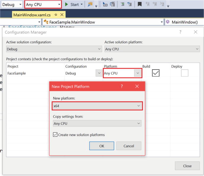
Figure 5-12. Setting the CPU architecture of the project in Configuration Manager
Face
There are four key components to the Face API: detection, alignment, orientation, and expressions. These are not hard and fast Kinect terms that must be memorized, but they are a useful way to describe the API’s features with single words. They can all be accessed by opening readers on the FaceFrameSource Data Source.
Obtaining Face Data
Data from the Face API is obtained in a manner similar to doing so for the other Data Sources. The primary differences are that we must designate a separate FaceFrameSource and FaceFrameReader for each face we are looking to pick out and that we have to extract a FaceFrameResult, which is what contains the recognized facial features and data, from each FaceFrame.
Listing 5-21. Private Variables Declaration to Obtain Face Data
KinectSensor kinect;const float InfraredSourceValueMaximum = (float)ushort.MaxValue;const float InfraredSourceScale = 0.75f;const float InfraredOutputValueMinimum = 0.01f;const float InfraredOutputValueMaximum = 1.0f;MultiSourceFrameReader multiSourceFrameReader;FrameDescription frameDescription;Body[] bodies;FaceFrameSource[] faceFrameSources;FaceFrameReader[] faceFrameReaders;FaceFrameResult[] faceFrameResults;WriteableBitmap infraredBitmap;ushort[] infraredPixels;DrawingGroup drawingGroup;DrawingImage drawingImageSource;List<Brush> faceBrushes;
In Listing 5-21, we declare arrays in which to contain the frame sources, readers, and results for all the faces that can be simultaneously tracked at an instant. Note that we also added an array for tracked bodies. While tracking body data is not a prerequisite to tracking facial data, in practice you will probably always do so anyway. Among other reasons, this is so we can update the FaceFrameSources to ensure that they are tracking faces from bodies visible in the scene.
Listing 5-22. Constructor for App Using Face Data
public MainWindow(){kinect = KinectSensor.GetDefault();InfraredFrameSource infraredFrameSource = kinect.InfraredFrameSource;multiSourceFrameReader = kinect.OpenMultiSourceFrameReader(FrameSourceTypes.Infrared | FrameSourceTypes.Body);multiSourceFrameReader.MultiSourceFrameArrived += MultiSource_FrameArrived;frameDescription = infraredFrameSource.FrameDescription;bodies = new Body[kinect.BodyFrameSource.BodyCount];FaceFrameFeatures faceFrameFeatures =FaceFrameFeatures.BoundingBoxInInfraredSpace| FaceFrameFeatures.PointsInInfraredSpace| FaceFrameFeatures.RotationOrientation| FaceFrameFeatures.FaceEngagement| FaceFrameFeatures.Glasses| FaceFrameFeatures.Happy| FaceFrameFeatures.LeftEyeClosed| FaceFrameFeatures.RightEyeClosed| FaceFrameFeatures.LookingAway| FaceFrameFeatures.MouthMoved| FaceFrameFeatures.MouthOpen;faceFrameSources = new FaceFrameSource[6];faceFrameReaders = new FaceFrameReader[6];faceFrameResults = new FaceFrameResult[6];faceBrushes = new List<Brush>(){Brushes.Pink,Brushes.Orange,Brushes.BlueViolet,Brushes.Aqua,Brushes.LawnGreen,Brushes. Chocolate};for (int i = 0; i < 6; i++){faceFrameSources[i] = new FaceFrameSource(kinect, 0, faceFrameFeatures);faceFrameReaders[i] = faceFrameSources[i].OpenReader();faceFrameReaders[i].FrameArrived += Face_FrameArrived;}infraredBitmap = new WriteableBitmap(frameDescription.Width,frameDescription.Height,96.0, 96.0,PixelFormats.Gray32Float,null);infraredPixels = new ushort[frameDescription.LengthInPixels];drawingGroup = new DrawingGroup();drawingImageSource = new DrawingImage(drawingGroup);kinect.Open();DataContext = this;InitializeComponent();}
With the Face API, we need to declare in advance which features we plan to extract from the FaceFrame. This is why we assign the desired features in the FaceFrameFeatures enum in Listing 5-22. In addition to the features listed, there are also FaceFrameFeatures_BoundingBoxInColorSpace and FaceFrameFeatures_PointsInColorSpace. We are using the infrared space equivalents, which is why we did not include them.
Tip
The Kinect’s face-detection algorithms are able to recognize faces using the infrared camera. They use infrared because it is lighting independent, and thus faces are bound to be accurately recognized in any lighting condition. Feature coordinates are internally translated by the API to color space using the CoordinateMapper class.
We create the arrays for the face frame sources, readers, and results for the number of faces that we are interested in tracking—in our case, all six. We then loop through the FaceFrameSource and FaceFrameReader arrays and create the FaceFrameSources and set up their readers. The constructor method for FaceFrameSource, new FaceFrameSource(kinect, 0, faceFrameFeatures), takes the Kinect sensor, initial tracking ID, and desired face frame features as inputs. The tracking ID is a property of the Body class, and we can use it to set the FaceFrameSource to track the face of a specific body.
For our sample app making use of face data, we will display the features on top of an infrared video stream. For this, we have to construct our ImageSource slightly differently. Instead of displaying the infrared stream’s WriteableBitmap directly, we create a DrawingGroup, which can be converted to an ImageSource by creating a DrawingImage out of it. As this is not a book on .NET or WPF, the peculiarities are not important. Just know that we can add multiple visual elements to a DrawingGroup and that DrawingImage is a type of ImageSource. Instead of returning the WriteableBitmap in the getter for our public ImageSource, we return the DrawingImage object, as follows:
public ImageSource ImageSource{get{return drawingImageSource;}}
Listing 5-23. FaceFrameReader Event Handler
private void Face_FrameArrived(object sender, FaceFrameArrivedEventArgs e){using (FaceFrame faceFrame = e.FrameReference.AcquireFrame()){if (faceFrame != null){int index = GetFaceSourceIndex(faceFrame.FaceFrameSource);faceFrameResults[index] = faceFrame.FaceFrameResult;}}}
In Listing 5-23, we save the FaceFrameResult, which is a property of FaceFrame, to our faceFrameResults array. We want to keep track of its index so that we can work with its respective frame source, frame reader, and body. Since we have a reference to its FaceFrameSource in the FaceFrame, we take the initiative of finding its index using GetFaceSoureIndex(FaceFrameSource faceFrameSource), as shown in Listing 5-24. The Face_FrameArrived event handler is applied to each reader.
Listing 5-24. Obtaining the Index of a FaceFrameSource
private int GetFaceSourceIndex(FaceFrameSource faceFrameSource){int index = -1;for (int i = 0; i < 6; i++){if (faceFrameSources[i] == faceFrameSource){index = i;break;}}return index;}
Finding the index is a straightforward matter. We loop through our faceFrameSources array and check whether any of them match the FaceFrameSource of the obtained FaceFrame. If they do, we know what index to put our FaceFrameResult in.
Listing 5-25. MultiSourceFrameReader Event Handler for Face-Detector App
private void MultiSource_FrameArrived(object sender, MultiSourceFrameArrivedEventArgs e){MultiSourceFrame multiSourceFrame = e.FrameReference.AcquireFrame();using (InfraredFrame infraredFrame = multiSourceFrame.InfraredFrameReference.AcquireFrame()){if (infraredFrame != null){using (KinectBuffer infraredBuffer = infraredFrame.LockImageBuffer()){ProcessInfraredFrameData(infraredBuffer.UnderlyingBuffer, infraredBuffer.Size);}}}using (BodyFrame bodyFrame = multiSourceFrame.BodyFrameReference.AcquireFrame()){if (bodyFrame != null){bodyFrame.GetAndRefreshBodyData(bodies);using (DrawingContext dc = drawingGroup.Open()){dc.DrawImage(infraredBitmap, new Rect(0, 0,infraredBitmap.Width,infraredBitmap.Height));for (int i = 0; i < 6; i++){if (faceFrameSources[i].IsTrackingIdValid){if (faceFrameResults[i] != null){DrawFace(i, faceFrameResults[i], dc);}}else{if (bodies[i].IsTracked){faceFrameSources[i].TrackingId = bodies[i].TrackingId;}}}}}}}private unsafe void ProcessInfraredFrameData(IntPtr infraredFrameData, uint infraredFrameDataSize){//infrared frame data is a 16-bit valueushort* frameData = (ushort*)infraredFrameData;//lock the target bitmapthis.infraredBitmap.Lock();//get the pointer to the bitmap's back bufferfloat* backBuffer = (float*)this.infraredBitmap.BackBuffer;//process the infrared datafor (int i = 0; i < (int)(infraredFrameDataSize / this.frameDescription.BytesPerPixel); ++i){//since we are displaying the image as a normalized grayscale image, we need to convert from//the ushort data (as provided by the InfraredFrame) to a value from//[InfraredOutputValueMinimum, InfraredOutputValueMaximum]backBuffer[i] = Math.Min(InfraredOutputValueMaximum, (((float)frameData[i] / InfraredSourceValueMaximum * InfraredSourceScale) * (1.0f - InfraredOutputValueMinimum)) + InfraredOutputValueMinimum);}//mark the entire bitmap as needing to be drawnthis.infraredBitmap.AddDirtyRect(new Int32Rect(0, 0, this.infraredBitmap.PixelWidth, this.infraredBitmap.PixelHeight));//unlock the bitmapthis.infraredBitmap.Unlock();}
In Listing 5-25, the event handler for the MultiSourceFrameReader collects infrared and body data. Seeing as this represents a single event that is fired repeatedly, as opposed to six different events as with the FaceFrameReader, it is better to include the drawing code in here. This way, we avoid having multiple unordered methods trying to access the DrawingGroup in a similar timeframe, all trying to overwrite it.
We obtain the infrared data in the same we did in Listing 3-14 in Chapter 3. The XAML front end is also the same as in Chapter 3. Inside of the using (BodyFrame bodyFrame = multiSourceFrame.BodyFrameReference.AcquireFrame()) { [...] } block we access the DrawingContext of drawingGroup. DrawingContext is a .NET construct that allows us to draw various types of media in a DrawingGroup (among other drawing-related objects). We start off by drawing our infrared image data as the background, and then we loop through the faceFrameResults and draw any facial data with the DrawFace(int index, FaceFrameResult faceFrameResult, DrawingContext drawingContext) method (which will be defined later). Keep in mind that we only do this if the faceFrameSources[i].IsTrackingIdValid property returns true. If not, we consider whether a body is being checked for index i and, if so, assign its TrackingId to its respective FaceFrameSource (faceFrameSources[i].TrackindId = bodies[i].TrackingId).
At this point, if you were to run the code, minus the DrawFace(...) method, it would obtain facial data and display an infrared feed to boot, but it would not actually indicate that it has obtained facial data, let alone do anything with it. We thus venture to the first Face API feature, detection, to inform the user that the face has been found by the Kinect.
Detection
In the Face API, detection refers to whether any faces belonging to bodies are visible in the Kinect’s field of view. In practice, the Face API achieves this by framing a face inside of a bounding box, as seen in Figure 5-13. This bounding box is a property of FaceFrameResult called either FaceBoundingBoxInInfraredSpace or FaceBoundingBoxInColorSpace depending on the image feed you are interested in. It is a RectI struct—a rectangle with integer coordinates. The RectI’s Top and Bottom fields each represent a pixel coordinate on the vertical axis, and the Right and Left fields represent the same on a horizontal axis. Thus, a RectI with the following fields would represent a rectangle whose top-left coordinate is (0, 10), and its size would be 13 pixels wide and 10 pixels in height.
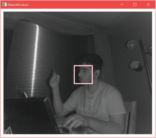
Figure 5-13. Bounding box representation (FaceBoundingBoxInInfraredSpace) around a detected face. Note that the box drawn on screen is thicker than the actual bounding box, given that the pen used to draw it has a thickness.
RectI box = new RectI(); //has no constructorBox.Top = 10;Box.Bottom = 20;Box.Left = 0;Box.Right = 13;
Before we can draw the bounding box on our infrared image, it would be prudent for us to ensure that the box fits within the image. Hence, when new FaceFrameResults are collected in Face_FrameArrived(...), we should reject results whose bounding boxes do not fit. This involves a small edit to Face_FrameArrived(...), whose initial version we saw in Listing 5-23.
Listing 5-26. Face Bounding Box Validation Method Call
if (faceFrame != null){int index = GetFaceSourceIndex(faceFrame.FaceFrameSource);if (ValidateFaceBoundingBox(faceFrame.FaceFrameResult)){faceFrameResults[index] = faceFrame.FaceFrameResult;}else{faceFrameResults[index] = null;}}
In Listing 5-26, we check to see if the bounding box is within the confines of the image with our custom ValidateFaceBoundingBox (FaceFrameResult faceFrameResult) method and reject the FaceFrameResult if it is not.
Listing 5-27. Face Bounding Box Validation
private bool ValidateFaceBoundingBox(FaceFrameResult faceFrameResult){bool isFaceValid = faceFrameResult != null;if (isFaceValid){RectI boundingBox = faceFrameResult.FaceBoundingBoxInInfraredSpace;if (boundingBox!= null){isFaceValid = (boundingBox.Right - boundingBox.Left) > 0 &&(boundingBox.Bottom - boundingBox.Top) > 0 &&boundingBox.Right <= frameDescription.Width &&boundingBox.Bottom <= frameDescription.Height;}}return isFaceValid;}
In Listing 5-27, we immediately reject empty FaceFrameResults. We then check to see if the box has meaningful coordinates, e.g., the right side of the bounding box is to the right of the box’s left side ((boundingBox.Right – boundingBox.Left) > 0). If it does, we approve of the FaceFrameResult, and it can be used in the DrawFace(...) method to draw the bounding box.
Listing 5-28. Drawing a Bounding Box
private void DrawFace(int index, FaceFrameResult faceFrameResult, DrawingContext drawingContext){Brush drawingBrush = faceBrushes[0];if (index < 6){drawingBrush = faceBrushes[index];}Pen drawingPen = new Pen(drawingBrush, 4);RectI faceBoxSource = faceFrameResult.FaceBoundingBoxInInfraredSpace;Rect faceBox = new Rect(faceBoxSource.Left, faceBoxSource.Top, faceBoxSource.Right - faceBoxSource.Left, faceBoxSource.Bottom - faceBoxSource.Top);drawingContext.DrawRectangle(null, drawingPen, faceBox);}
Listing 5-28 features the DrawFace(...) method we called earlier in the MultiFrameSourceReader event handler in Listing 5-25. We start by picking a Brush, which contains our desired color for the boxes drawn around faces. The brushes are from a list initialized in the app constructor as such:
faceBrushes = List<Brush>(){Brushes.Pink,Brushes.Orange,[...] //Add six brushes in total with differing colors};
The brush is then used to create a Pen that includes the desired thickness of the box’s outline as well. Finally, we create a rectangle based on the bounding box in FaceFrameResult and draw the rectangle on the DrawingContext, which will then display it to the front end. The compiled result will resemble the previously shown Figure 5-13.
Alignment
Alignment refers to Face API’s ability to easily detect five facial landmarks on a face. These landmarks, or points, consist of both eyes, the tip of the nose, and both corners of the mouth. They can be obtained from the FacePointsInInfraredSpace or FacePointsInColorSpace properties of FaceFrameResult (again, the difference between both is which image feed the landmarks map to). FacePointsInXSpace is an IReadOnlyDictionary<FacePointType, PointF>, where FacePointType refers to the title of the point (e.g., MouthCornerLeft) and PointF is a 2D coordinate with float members.
Generally, the points will be found within the bounding box, but it is better to ensure that they fit within the image confines anyway. The ValidateFaceBoundingBox(...) method from Listing 5-27 can be altered to accommodate this check.
Listing 5-29. Face Bounding Box and Points Validation
private bool ValidateFaceBoxAndPoints(FaceFrameResult faceFrameResult){bool isFaceValid = faceFrameResult != null;if (isFaceValid){RectI boundingBox = faceFrameResult.FaceBoundingBoxInInfraredSpace;if (boundingBox != null){[...] //Check if bounding box is validif (isFaceValid){var facePoints = faceFrameResult.FacePointsInInfraredSpace;if (facePoints != null){foreach (PointF pointF in facePoints.Values){bool isFacePointValid = pointF.X > 0.0f &&pointF.Y > 0.0f &&pointF.X < frameDescription.Width &&pointF.Y < frameDescription.Height;if (!isFacePointValid){isFaceValid = false;break;}}}}}}return isFaceValid;}
In Listing 5-29, we modified the ValidateFaceBoundingBox(...) method to conduct this check. The check consists of looping through the dictionary of face points and confirming that their x and y values fit in the image. On a side note, the method signature was also altered to reflect its new duties. Make sure to update the method call in Face_FrameFrameArrived(...).
Listing 5-30. Indicating Facial Landmarks on an Image Feed
...drawingContext.DrawRectangle(null, drawingPen, faceBox);//rest of DrawFace(...) bodyif (faceFrameResult.FaceBoundingBoxInInfraredSpace != null){foreach (PointF pointF in faceFrameResult.FacePointsInInfraredSpace.Values){drawingContext.DrawEllipse(null, drawingPen, new Point(pointF.X, pointF.Y), 0.4, 0.4);}}
In Listing 5-30, we loop through every face point in faceFrameResult and draw an ellipse on the location of the landmark on the image. The final result looks like Figure 5-14.

Figure 5-14. Facial landmark locations drawn on an infrared image
Orientation
The Face API gives us access to the face’s orientation, facing the Kinect, in 3D space. It can be accessed through FaceFrameResult’s FaceRotationQuaternion property. It is defined with a Vector4. The face orientation is given as a quaternion, similar to joint orientations. This was again done to avoid gimbal lock. Face orientation can be useful in many circumstances, but gaze tracking deserves special mention. It is not possible to determine where a user is looking with the Kinect API, but knowing in which direction their face is pointing is good enough for most use cases and is the solution that most unspecialized commercial systems employ.
The Kinect SDK Browser’s FaceBasics-WPF sample includes a convenient method by which to obtain a Euler angle in degrees from the face-rotation quaternion. If you are using a game engine or DirectX, you might choose to simply feed the quaternion into them directly, but if you are making a relatively simple app that does something like checking whether a head is tilting, using Euler angles with a heuristic system might be less work for you.
Listing 5-31. Method to Obtain Euler Angles from Face-Rotation Quaternion
/**usage:int pitch, yaw, roll; ExtractFaceRotationInDegrees(faceFrameResult.FaceRotationQuaternion, out pitch, out yaw, out roll);**/private static void ExtractFaceRotationInDegrees(Vector4 rotQuaternion, out int pitch, out int yaw, out int roll){double x = rotQuaternion.X;double y = rotQuaternion.Y;double z = rotQuaternion.Z;double w = rotQuaternion.W;double yawD, pitchD, rollD;pitchD = Math.Atan2(2 * ((y * z) + (w * x)), (w * w) - (x * x) - (y * y) + (z * z)) / Math.PI * 180.0;yawD = Math.Asin(2 * ((w * y) - (x * z))) / Math.PI * 180.0;rollD = Math.Atan2(2 * ((x * y) + (w * z)), (w * w) + (x * x) - (y * y) - (z * z)) / Math.PI * 180.0;double increment = 5.0;pitch = (int)(Math.Floor((pitchD + ((increment / 2.0) * (pitchD > 0 ? 1.0 : -1.0))) / increment) * increment);yaw = (int)(Math.Floor((yawD + ((increment / 2.0) * (yawD > 0 ? 1.0 : -1.0))) / increment) * increment);roll = (int)(Math.Floor((rollD + ((increment / 2.0) * (rollD > 0 ? 1.0 : -1.0))) / increment) * increment);}
The formulas in Listing 5-31 might look complex to the uninitiated, but you should not have to worry about their specifics. The first three formulas that calculate pitchD, yawD, and rollD are responsible for converting our quaternion into a Euler angle. The next three, used to calculate pitch, yaw, and roll, are clamping functions. They basically round the Euler angle values to the nearest multiple of the increment value. For example, if the pitch is actually 53.01666666 degrees and we set the increment to 5, it would appear as 55 degrees.
Tip
Unfamiliar by what is conveyed here by pitch, yaw, and roll? Chances are you have seen these terms used to describe the direction of a plane, but might have forgotten which one refers to which axis. Pitch describes rotation around the x-axis, such as when a person is nodding in agreement; yaw describes rotation around the y-axis, such as when a person is shaking their head from side to side in disagreement; and roll describes rotation around the z-axis, such as when a person is tilting their head. When the pitch, yaw, and roll are all 0 degrees, the user is facing the Kinect camera directly.
Expressions
Expressions constitute the final portion of the Face API’s capabilities. You might have noticed that the Body class has a handful of members, namely Activities, Appearance, Engaged, and Expressions, that are unusable. These were included for cross-compatibility with the Xbox Kinect API. However, we are able to access the same capabilities though the Face API. The Face API has a series of binary classifiers that can be used to determine whether a person is happy, wearing glasses, has their left or right eye closed, is looking away, is engaged with the application, if their mouth has moved, and if their mouth is open. In the case of looking away and engagement, the classifiers assume that the user is facing toward the Kinect. Thus, if you use these classifiers in your app, make sure that the Kinect is above or beneath the screen or location that the user is supposed to be looking at.
The expressions can be accessed from the FaceProperties property of FaceFrameResult. FaceProperties is an IReadOnlyDictionary<FaceProperty, DetectionResult>. FaceProperty is an enum that contains the title of the expression (e.g., Happy or Engaged), and DetectionResult is an enum that be Yes, No, Maybe, or Unknown to indicate whether the expression has been detected.
To demonstrate, let us display a smiley face on the screen when the user is happy.
Listing 5-32. Displaying a Smiley Face When a Face Indicates Happiness
if (faceFrameResult.FaceProperties != null){if (faceFrameResult.FaceProperties[FaceProperty.Happy] == DetectionResult.Yes){Point nosePoint = new Point(faceFrameResult.FacePointsInInfraredSpace[FacePointType.Nose].X,faceFrameResult.FacePointsInInfraredSpace[FacePointType.Nose].Y);drawingContext.DrawText(new FormattedText("☺",System.Globalization.CultureInfo.GetCultureInfo("en-us"),FlowDirection.RightToLeft,new Typeface("Segoe UI"),68,drawingBrush),nosePoint);}}
Listing 5-32 is a snippet of code that can be include in the DrawFace(...) method to draw a ☺ character on the screen when the DetectionResult of the Happy classifier holds a Yes value. We use the coordinates of the Nose face point to draw the character. The character’s top-right corner, which consists of empty space, is set at the location of the nose. DrawingContext’s DrawText(...) method requires a FormattedText and Point to output text onto the image. In practice, a TextBlock XAML control can offer more customization options than can those available through FormattedText, but it requires a bit more wiring. The completed work should look like Figure 5-15.

Figure 5-15. Smiley face character displayed when face appears to be happy. The bounding box and facial landmark visualizations were omitted in this picture.
Tip
Avoid showing your teeth and looking directly toward the camera in an infrared picture so as to avoid looking like a heinous creature.
HD Face
For casual usage, the Face API will typically suffice. For precision work like modeling or tracking very specific parts of the face in realtime, the HD Face API will better serve you. Whereas the regular Face API performs tracking and classification work in 2D, HD Face is entirely in 3D and provides its coordinates as CameraSpacePoints. Its range is more limited than that of the Face API, at 0.5m to 2m (1.64 ft. to 6.56 ft.), and, like the Face API, facial tracking of only one user at a time per reader is supported.
The face tracked by HD Face is represented through 1,347 vertices, as portrayed in Figure 5-16. Anyone who has used face tracking in Kinect for Windows SDK v1 will remember that there used to be a mere hundred or so vertices and that we used to build entire commercial-grade applications out of them!

Figure 5-16. HD Face vertices recreating a detected face
Some of the more common vertices can be accessed through the HighDetailFacePoints enum and are listed in Table 5-1. This provides a manner in which to refer to vertices of interest (e.g., tip of nose) without resorting to remembering their index number in the vertices list.
Table 5-1. Vertices Referable Through the HighDetailFacePoints Enumeration
Key (preface with HighDetailFacePoints_) | Vertex Index |
|---|---|
EyeLeft | 0 |
LefteyeInnercorner | 210 |
LefteyeOutercorner | 469 |
LefteyeMidtop | 241 |
LefteyeMidbottom | 1104 |
RighteyeInnercorner | 843 |
RighteyeOutercorner | 1117 |
RighteyeMidtop | 731 |
RighteyeMidbottom | 1090 |
LefteyebrowInner | 346 |
LefteyebrowOuter | 140 |
LefteyebrowCenter | 222 |
RighteyebrowInner | 803 |
RighteyebrowOuter | 758 |
RighteyebrowCenter | 849 |
MouthLeftcorner | 91 |
MouthRightcorner | 687 |
MouthUpperlipMidtop | 19 |
MouthUpperlipMidbottom | 1072 |
MouthLowerlipMidtop | 10 |
MouthLowerlipMidbottom | 8 |
NoseTip | 18 |
NoseBottom | 14 |
NoseBottomleft | 156 |
NoseBottomright | 783 |
NoseTop | 24 |
NoseTopleft | 151 |
NoseTopright | 772 |
ForeheadCenter | 28 |
LeftcheekCenter | 412 |
RightcheekCenter | 933 |
Leftcheekbone | 458 |
Rightcheekbone | 674 |
ChinCenter | 4 |
LowerjawLeftend | 1307 |
LowerjawRightend | 1327 |
Note
The HighDetailFacePoint keys must be prefaced with HighDetailFacePoints_ when being used. For example, EyeLeft must be referred to as HighDetailFacePoints_EyeLeft in your code.
The face can also be recreated through 94 shape units. This entails taking a “standard” face model and applying shape unit deformations as well as a scaling factor. A standard face model is essentially a face model averaged from the faces of many, many individuals. This averaging has already been done by the Kinect team, so we can use the standard face model without further calibration. Shape units are numeric weights, typically around –2f to +2f, that indicate to the HD Face API how to deform the face in specific areas.
Other than tracking models of the face, HD Face has a few other nifty tricks up its sleeves. Like the Face API, it can provide the orientation of the face as a rotational quaternion. Additionally, it can provide the pivot point of the head. This is analogous to the head joint in the regular Body skeleton, but has a different vertical point to better describe the point at which the head pivots around. The hair color and skin color of a user are also provided by the Kinect as a property of the face model.
Finally, we have access to animation units. These are comparable to the expression classifiers for the Face API, but they describe a range instead of simply providing a binary classification. Typically, they provide values between 0f to 1f that depend on the progression of the animation. For example, for the JawOpen animation unit, a value of 0.2f would indicate that the jaw is barely open, whereas 0.93f would mean that that the jaw is practically open to the greatest possible extent. Three of the animation units—JawSlideRight, RightEyebrowLowerer, and LeftEyebrowLowerer—have numeric weights between –1f and +1f. This is because they describe motions that can be reversed in another direction. For example, when JawSlideRight has a value of –0.76f, the jaw is slid far along toward the left. The available animation units are: JawOpen, LipPucker, JawSlideRight, LipStretcherRight, LipStretcherLeft, LipCornerPullerLeft, LipCornerPullerRight, LipCornerDepressorLeft, LipCornerDepressorRight, LeftcheekPuff, RightcheekPuff, LefteyeClosed, RighteyeClosed, RighteyebrowLowerer, LefteyebrowLowerer, LowerlipDepressorLeft, and LowerlipDepressorRight. Animation units can be applied on the face model to alter its appearance. Performing gestures on the face that are not covered by animation units will not be reflected in the face model. For example, since there is no animation unit for crinkling your nose, a 3D visualization of the face like the one in Figure 5-16 will not be shown to be crinkling its nose.
Obtaining HD Face data
Data procurement for HD Face is akin to that for any other Data Source. As you could have expected, there are a reader and a Data Source for HD face data, HighDefinitionFaceFrameReader and HighDefinitionFaceFrameSource, respectively, from which we collect frames containing data. The resulting HighDefinitionFaceFrame is responsible for the two central pieces of HD Face data: FaceModel and FaceAlignment.
FaceModel contains the structural details of the face. Namely, this includes the FaceShapeDeformations property, which is an IReadOnlyDictionary<FaceShapeDeformations, float> describing the shape units applied to the face. It also includes a TriangleIndices property, an IReadOnlyList<uint> that lists the 7,890 indices of the triangles used to create the face mesh for modeling; SkinColor and HairColor, which are 32-bit unsigned integers that describe a 4-byte ARGB color describing the skin color or hair color; Scale, a float representing the scaling factor of the face; and CalculateVerticesForAlignment(FaceAlignment faceAlignment), a method that furnishes a list of CameraSpacePoints representing facial vertices calculated from the FaceAlignment.
Note
Hair and skin color can only be obtained after the face model has been “captured” using FaceModelBuilder. The process to do so is described in the “Face Capture” section that follows the current section.
On a side note, converting the uint values of SkinColor and HairColor to colors involves shifting their bits to expose the ARGB data. The following code will accomplish this:
uint color = faceModel.SkinColor;Byte A = (byte) (color >> 24);Byte B = (byte) (color >> 16);Byte G = (byte) (color >> 8);Byte R = (byte) (color >> 0);Color skinColor = Color.FromArgb(A, R, G, B);
FaceAlignment contains orientation and animation unit data. Its members include AnimationUnits, which is an IReadOnlyDictionary<FaceShapeAnimations, float>, FaceShapeAnimations being an enum describing the animation unit FaceOrientation, a Vector4 representing a quaternion, and HeadPivotPoint, which is a CameraSpacePoint. Since the locations of vertices depend on how the face model is rotated, in practice it is more critical to our application than is FaceModel, for which we can just use the default average face model provided by the Kinect.
Listing 5-33. Private Variable Declaration to Obtain HD Face Data
private KinectSensor kinect;private BodyFrameReader bodyFrameReader;private HighDefinitionFaceFrameSource HDFaceFrameSource;private HighDefinitionFaceFrameReader HDFaceFrameReader;private FaceModel faceModel;private FaceAlignment faceAlignment;
Listing 5-33 features the essential private variables for HD face tracking. We see that body data is to be tracked in addition to face data. While this was imperative for regular face tracking, it is downright necessary for HD face tracking. Since only one face can be tracked in HD, the TrackingId of the face must be manually picked from one of the available bodies.
Listing 5-34. Initializing HD Face Data Source and Reader
HDFaceFrameSource = new HighDefinitionFaceFrameSource(Kinect);HDFaceFrameReader = HDFaceFrameSource.OpenReader();HDFaceFrameReader.FrameArrived += HDFace_FrameArrived;faceAlignment = new FaceAlignment();
In Listing 5-34, HD Face’s Data Source is shown to be perhaps the simplest no-frills Data Source to get running. Additionally, we create an instance of the FaceAlignment object to hold its data throughout the lifetime of the application. Like with an array of Bodies, FaceAlignment will be updated instead of being re-initialized on each HD Face frame.
Listing 5-35. BodyFrameReader Event Handler for HD Face Tracking
private void Body_FrameArrived(object sender, BodyFrameArrivedEventArgs e){using (BodyFrame bodyFrame = e.FrameReference.AcquireFrame()){if (bodyFrame != null){Body[] bodies = new Body[bodyFrame.BodyCount];bodyFrame.GetAndRefreshBodyData(bodies);Body body = bodies.Where(b => b.IsTracked).FirstOrDefault();if (!HDFaceFrameSource.IsTrackingIdValid){if (body != null){HDFaceFrameSource.TrackingId = body.TrackingId;}}}}}
In Listing 5-35, our goal is to determine which body’s face to track. We otherwise do not need to touch the skeleton data. Using a bit of LINQ, we pick the first available body, and if the HighDefinitionFaceFrameSource is not currently tracking a body, we assign it a body to track.
Listing 5-36. HighDefinitionFaceFrameReader Event Handler
private void HDFAce_FrameArrived(object sender, HighDefinitionFaceFrameArrivedEventArgs e){using (HighDefinitionFaceFrame HDFrame = e.FrameReference.AcquireFrame()){if (HDFrame!= null && HDFrame.IsFaceTracked){HDFrame.GetAndRefreshFaceAlignmentResult(faceAlignment);if (faceModel == null) {faceModel = HDFrame.FaceModel;}ProcessHDFaceData();}}}
In Listing 5-36, we see that FaceAlignment is collected through the GetAndRefereshFaceAlignmentResult(FaceAlignment faceAlignment) method of HighDefinitionFaceFrame. If we so choose, we can also grab the FaceModel, but this is not necessary. The standard face model provided by the Kinect could be initialized in the constructor and coupled with the FaceAlignment to provide a decent representation of a user’s face. After this point, we are free to process our data for whatever purpose.
It should be noted that HighDefinitionFaceFrame has an additional property, FaceAlignmentQuality, which is an enum with High and Low values to describe how accurate the obtained FaceAlignment is.
Listing 5-37. Processing HD Face Data
private void ProcessHDFaceData(){if (faceModel != null){var vertices = faceModel.CalculateVerticesForAlignment(faceAlignment);//Perform work with vertices, such as displaying on screen}}
Other than the vertices, the rest of HD Face’s data can be gleaned from FaceModel and FaceAlignment directly. As mentioned earlier, the position of the vertices in a 3D space depends on how their constituent model is rotated in 3D space. Hence, in Listing 5-37 we must calculate them with the CalculateVerticesForAlignment(FaceAlignment faceAlignment) method. This is not a static method; it does depend on the data of a FaceModel instance. However, it can be used on the data in the default initialization of FaceModel without gathering anything from HighDefinitionFaceFrames. Despite this possibility, HD Face unsurprisingly shines brightest when it gets a chance to reconstruct a FaceModel from an analysis of a user’s face, which we will cover next .
Face Capture & Modeling
With the vertices provided from FaceModel and FaceAlignment, we can create a 3D mesh of the user’s face by connecting them into triangles. To get a more accurate representation, however, we have to use the FaceModelBuilder class to produce a FaceModel with shape unit deformations applied. FaceModelBuilder needs to capture 16 frames from all sides of the face. Thus, with the help of the API, you will have to inform users of your app when to move their faces to be properly captured. Your users should take off any accessories on or near their faces, such as glasses or hats.
To learn how to use FaceModelBuilder and create a mesh with or without it, we will turn to the HDFaceBasics-WPF sample in the SDK Browser. This app (shown in Figure 5-17) creates a 3D visualization of a user, and once face capture has been completed, this visualization is deformed to look more like the user’s face.

Figure 5-17. 3D visualization created by HD Face. User face has not yet been captured
In Figure 5-17, we see that HD Face is Ready To Start Capture. Pressing Start Capture will fire off FaceModelBuilder, which will instruct the user in which direction to tilt their face in the Builder Status Text Block.
In the InitializeHDFace() method of MainWindow.xaml.cs, the process of creating a 3D mesh is started off with the InitializeMesh() and UpdateMesh() methods. These methods take the vertices, create triangles from them, and then apply them to a MeshGeometry3D object that is responsible for the 3D visualization we see on the front end. MeshGeometry3D is a part of the System.Windows.Media.Media3D namespace that allows us to build simple 3D applications in WPF (the functionalities of this library are sometimes colloquially referred to as WPF 3D).
Listing 5-38. Initializing a 3D Mesh from HD Face Data
private void InitializeMesh(){var vertices = this.currentFaceModel.CalculateVerticesForAlignment(this.currentFaceAlignment);var triangleIndices = this.currentFaceModel.TriangleIndices;var indices = new Int32Collection(triangleIndices.Count);for (int i = 0; i < triangleIndices.Count; i += 3){uint index01 = triangleIndices[i];uint index02 = triangleIndices[i + 1];uint index03 = triangleIndices[i + 2];indices.Add((int)index03);indices.Add((int)index02);indices.Add((int)index01);}this.theGeometry.TriangleIndices = indices;this.theGeometry.Normals = null;this.theGeometry.Positions = new Point3DCollection();this.theGeometry.TextureCoordinates = new PointCollection();foreach (var vert in vertices){this.theGeometry.Positions.Add(new Point3D(vert.X, vert.Y, -vert.Z));this.theGeometry.TextureCoordinates.Add(new Point());}}
In Listing 5-38, we have all the code necessary to turn vertices into a 3D mesh. After grabbing the vertices and triangle indices of the standard model face, we add the triangle indices to an Int32Collection for use by a MeshGeometry3D instance. This will indicate which vertices create which triangles .
When adding the triangle indices to the Int32Collection, we add them in reverse order (i.e., index03, index02, index01). This is because WPF 3D creates front-facing mesh triangles in counterclockwise order. Setting them in clockwise would make the mesh triangles face backward.
After setting the indices to the MeshGeometry3D (known here as theGeometry and initialized in the XAML code), we add the vertices. The z coordinate of the vertices is made negative so that the face appears behind the screen, as the positive z-axis sticks out of the screen. TextureCoordinates are set as null values, as we do not intend to texture our face.
Listing 5-39. Updating a 3D Mesh from HD Face Data
private void UpdateMesh(){var vertices = this.currentFaceModel.CalculateVerticesForAlignment(this.currentFaceAlignment);for (int i = 0; i < vertices.Count; i++){var vert = vertices[i];this.theGeometry.Positions[i] = new Point3D(vert.X, vert.Y, -vert.Z);}}
Since the triangle indices are already set into the MeshGeometry3D, we only need to update the position of the vertices over time. To accomplish this, UpdateMesh() (Listing 5-39) is called every time HighDefinitionFaceFrameReader provides a new frame.
Listing 5-40. Initializing FaceModelBuilder
private void StartCapture(){this.StopFaceCapture();this.faceModelBuilder = null;this.faceModelBuilder = this.highDefinitionFaceFrameSource.OpenModelBuilder(FaceModelBuilderAttributes.None);this.faceModelBuilder.BeginFaceDataCollection();this.faceModelBuilder.CollectionCompleted += this.HdFaceBuilder_CollectionCompleted;}
In Listing 5-40, the StartCapture() method encapsulates the initializing process of FaceModelBuilder. StopFaceCapture() disposes of any existing FaceModelBuilder so that we can start fresh. We assign the FaceModelBuilder by opening it from the HighDefinitionFaceFrameSource’s OpenModelBuilder(FaceModelBuilderAttribute enabledAttributes) method. The other parameters we can include are HairColor and SkinColor. If we wanted both, we could do OpenModelBuilder(FaceModelBuilderAttribute.HairColor | FaceModelBuilderAttribute.SkinColor).
The FaceModelBulder is started with its BeginFaceDataCollection() method, and we attach an event handler to its CollectionCompleted event so that we can tell it to deform the face after the new FaceModel has been created from it .
Listing 5-41. Creating a New FaceModel from FaceModelBuilder’s Analysis
private void HdFaceBuilder_CollectionCompleted(object sender, FaceModelBuilderCollectionCompletedEventArgs e){var modelData = e.ModelData;this.currentFaceModel = modelData.ProduceFaceModel();this.faceModelBuilder.Dispose();this.faceModelBuilder = null;this.CurrentBuilderStatus = "Capture Complete";}
Once the FaceModelBuilder has finished capturing all its requisite frames (Listing 5-41), it provides us with a FaceModelData object whose ProduceFaceModel() method creates the more tailored FaceModel that we desire. It will be used by UpdateMesh() automatically to alter the mesh.
Listing 5-42. Determining FaceModelBuilder’s Status
private void CheckOnBuilderStatus(){if (this.faceModelBuilder == null){return;}string newStatus = string.Empty;var captureStatus = this.faceModelBuilder.CaptureStatus;newStatus += captureStatus.ToString();var collectionStatus = this.faceModelBuilder.CollectionStatus;newStatus += ", " + GetCollectionStatusText(collectionStatus);this.CurrentBuilderStatus = newStatus;}
Two final interesting bits of FaceModelBuilder functionality are its CaptureStatus and CollectionStatus properties (Listing 5-42). They provide capture-quality warnings and details as to what frames are left to capture, respectively. The FaceModelBuilderCaptureStatus enum contains the OtherViewsNeeded, LostFaceTrack, FaceTooFar, FaceTooNear, GoodFrameCapture, and SystemError values. The FaceModelBuilderCollectionStatus enum contains the MoreFramesNeeded, FrontViewFramesNeeded, LeftViewsNeeded, TiltedUpViewsNeeded, and Complete values. These can be used to provide tips to users on how they should position their faces to complete face capture .
Conclusion
In this chapter, we conducted a comprehensive overview of the various body- and face-tracking features of the Kinect. We learned how these tracking features were segmented into the BodyFrameSource, BodyIndexFrameSource, FaceFrameSource, and HighDefinitionFaceFrameSource Data Sources. While we have not yet touched upon gestures, by learning about the properties and members of the various Data Sources, we can see how they might come to be used heuristically. Fortunately, the Kinect includes some tools that will help us avoid such tedious and manual labor.
This particular conclusion is more than just the parting words of Chapter 5. It marks a symbolic culmination of what can be considered Part I of this book. We spent the last several chapters understanding and extricating data from the various sensors of the Kinect. These are the fundamental building blocks of Kinect applications, and if you were to stop reading at this point (please don’t), you would be able to build your own Kinect solutions from scratch with knowledge of practically the full API.
Building Kinect applications consists of more than just what is in the Kinect, however. How its data gets processed by other technologies, such as computer vision, machine learning, and game engines, will be more responsible for whether your solution is a simple Kinect data viewer or a full-fledged consumer- or commercial-grade application. In the next chapter, we will begin looking at computer-vision and image-processing techniques using the Kinect so that we can derive meaning from otherwise flat images.