Rendering is the last stage in the 3D computer graphics production pipeline. In computer graphics, rendering is the computation process involved to convert three-dimensional objects into 2D images or a series of images.
We can divide rendering into two categories.
Offline rendering
Real-time rendering
Generally, we use offline rendering, to convert a 3D scene into a super-realistic image. It can take a huge amount of time to render the image while using real-time, or online, rendering computation very fast and interactively. Commonly we use offline rendering for movies and commercials and online rendering for the game industry.
Integration with Blender
In this section, I’ll cover how you can use your created maps with Blender. I will use the Cycles render engine at the beginning, and after that, I will show how you can use your maps with the EEVEE render engine (Figure 17-1). Let’s see first how to change the render engine inside Blender. As this book is specifically based on high-end texturing, you should already be familiar with the interface and tools of Blender; therefore, I am not going to explore them in detail here.
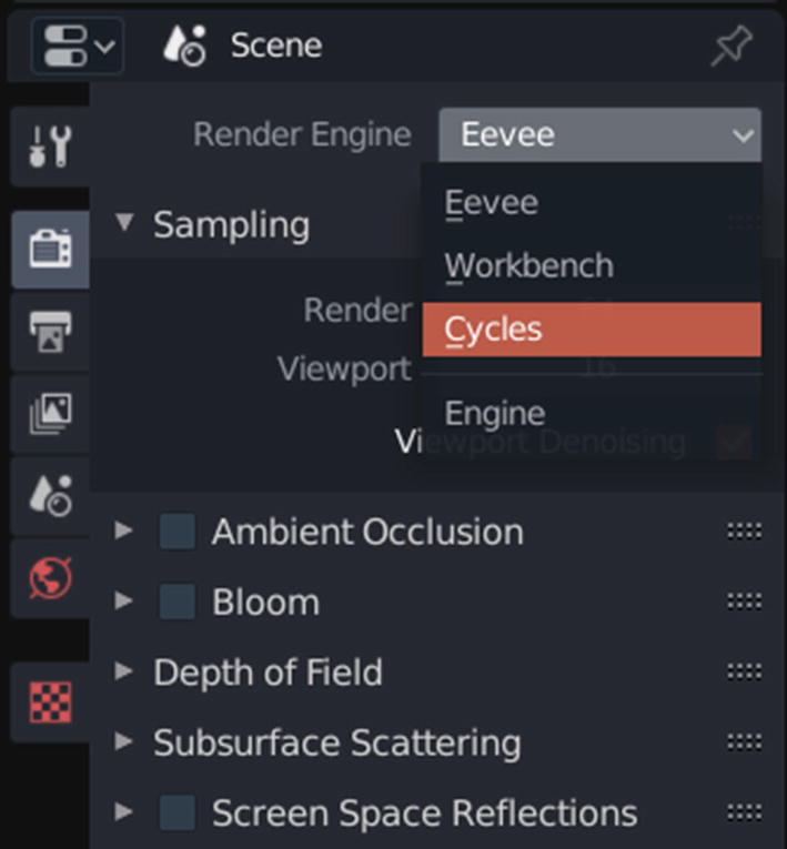
Click the camera icon in the Properties window of Blender. The first option should be Render Engine with a drop-down list that allows you to change your current render engine. Click that drop-down menu and choose Cycles (Figure 17-2).
Figure 17-2
Switching the render engine in Blender
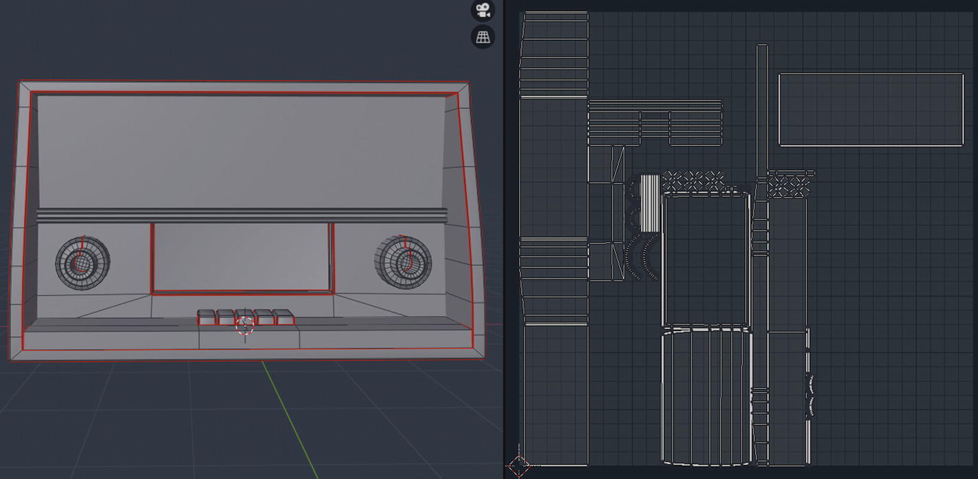
Now that you have chosen your render engine, let’s see how materials work in Blender. To use materials first, you will need a UV unwrapped mesh (Figure 17-3). If your mesh is not UV mapped, then you can get away with some procedural materials, but any material containing patterns or any kind of visual information will be warped.
Figure 17-3
UV unwrapped model that we will use in this chapter
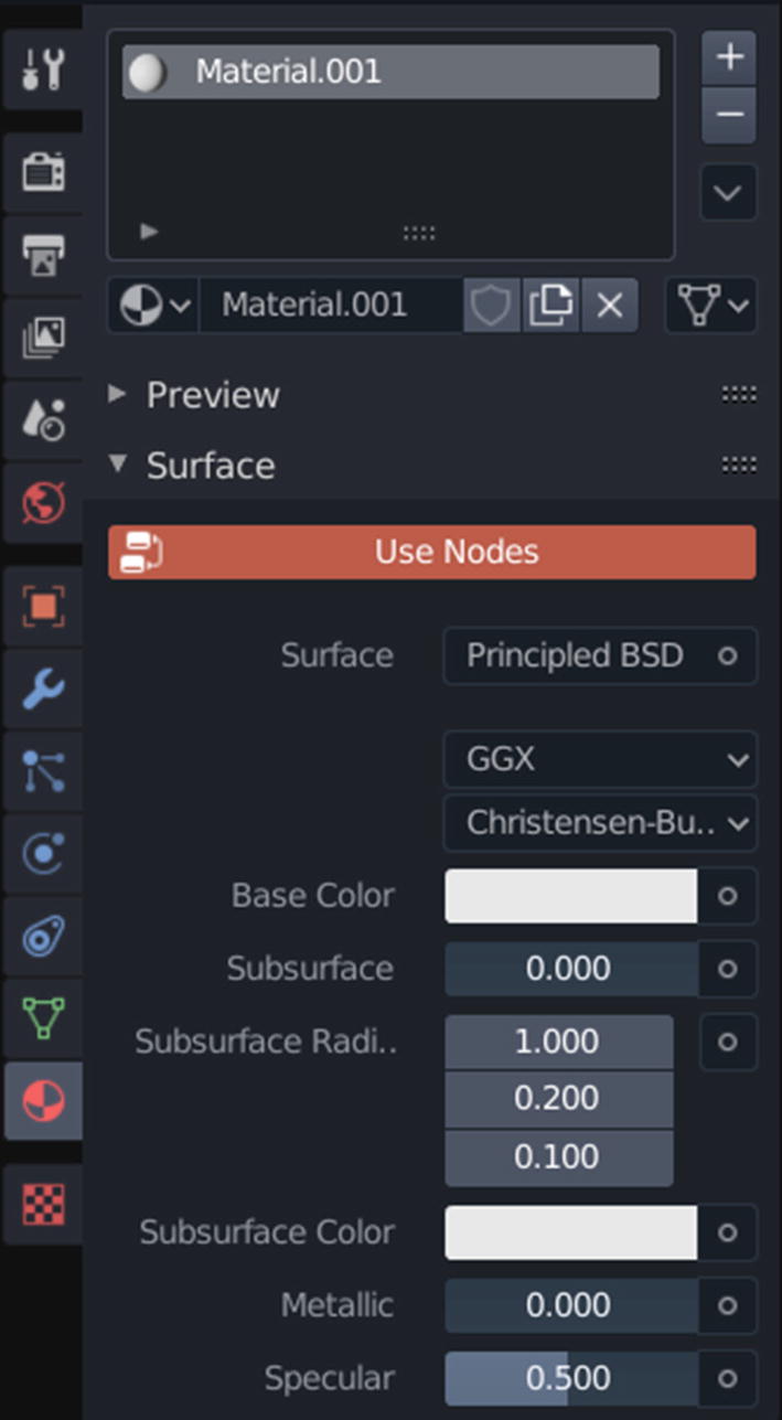
Once you have a UV mapped model loaded into your viewport, then your Properties window should show a multitude of new options. Clicking the checkered circle toward the bottom of the Properties window opens a material’s properties tab, where you will see all the available material parameters. At first, this tab should be empty with only the New button at the top of the window. Click it to create a new material.
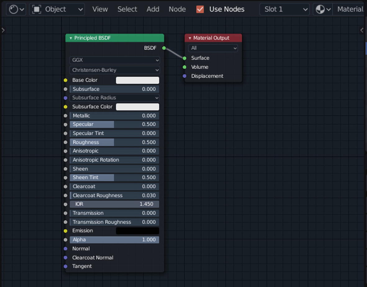
You should see a Use Nodes option highlighted in the window (Figure 17-4). This is important for you here because we will focus on creating materials in the node editor.
Figure 17-4
Material parameters
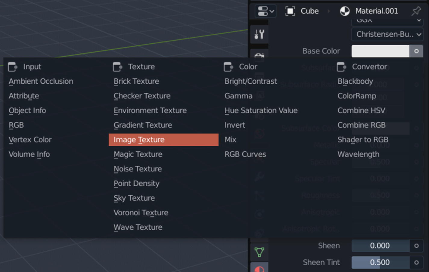
You can also set up your materials in this Properties window by clicking the small white circle next to each texture input slot. When you click the circle icon, a new window should open, giving you a list of operations that can be performed. From that list, choose the Image Texture option and then load the correct images into their respective slots (Figure 17-5).
Figure 17-5
Adding image texture to a texture slot
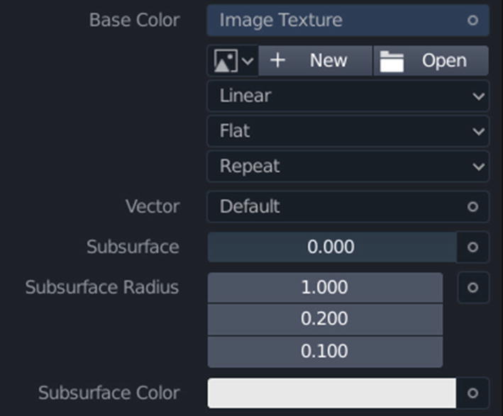
Once you have selected the Image Texture option, you will see new inputs and parameters (Figure 17-6).
Figure 17-6
Image texture parameters
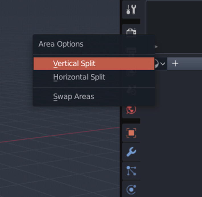
Now click the Open option to launch the file browser and navigate to the correct image that you want to load in that texture slot. Once you have loaded all the textures in their respective slots, then your model will be ready for rendering. But I don’t prefer this method because this does not give us the flexibility to edit the textures. So, we will do our material setup in the node editor. To open the node editor, place your pointer on the junction between the Properties window and the viewport until your pointer turns into a two-headed arrow. Then right-click and choose Vertical Split (Figure 17-7).
Figure 17-7
Splitting the workspace
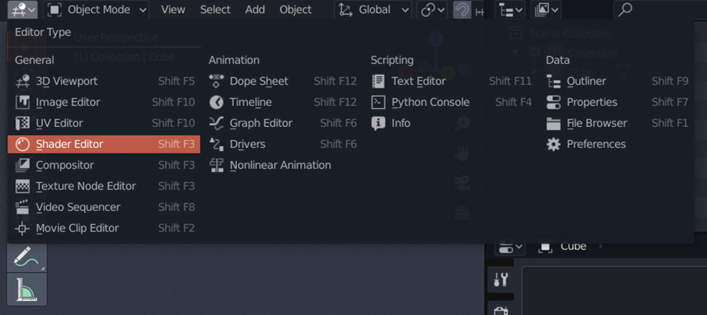
Your workspace will now split, so you now have two 3D workspaces. Click the Editor Type drop-down menu icon at the top-left corner of your window and choose Shader Editor from the list (Figure 17-8).
Figure 17-8
Changing the viewport type
Now your new editor section should change into a shader editor (Figure 17-9). You can edit how your textures work with the help of mathematical nodes. By default, a Principled BSDF shader is applied to your model when you use a material. You can, of course, change this at any time either from the material properties editor by changing the surface type or from the shader editor by deleting the default Principled BSDF shader and adding another shader node.
Figure 17-9
Shader editor in Blender
To add a new shader, you can press Shift+A, and this will open a new menu that allows you to choose which node you want to add to your tree. There are several categories from which you can choose nodes. In our case, we will mostly use the Shader category to add new shaders, the Textures category to add image textures, and sometimes the Vectors category (Figure 17-10).
Figure 17-10
Adding new shaders/nodes
If you are unable to find a node or don’t know which category it falls into, then you can use the search function located at the top of the menu. You can type in the name of the node that you want to add, and it will find it for you.
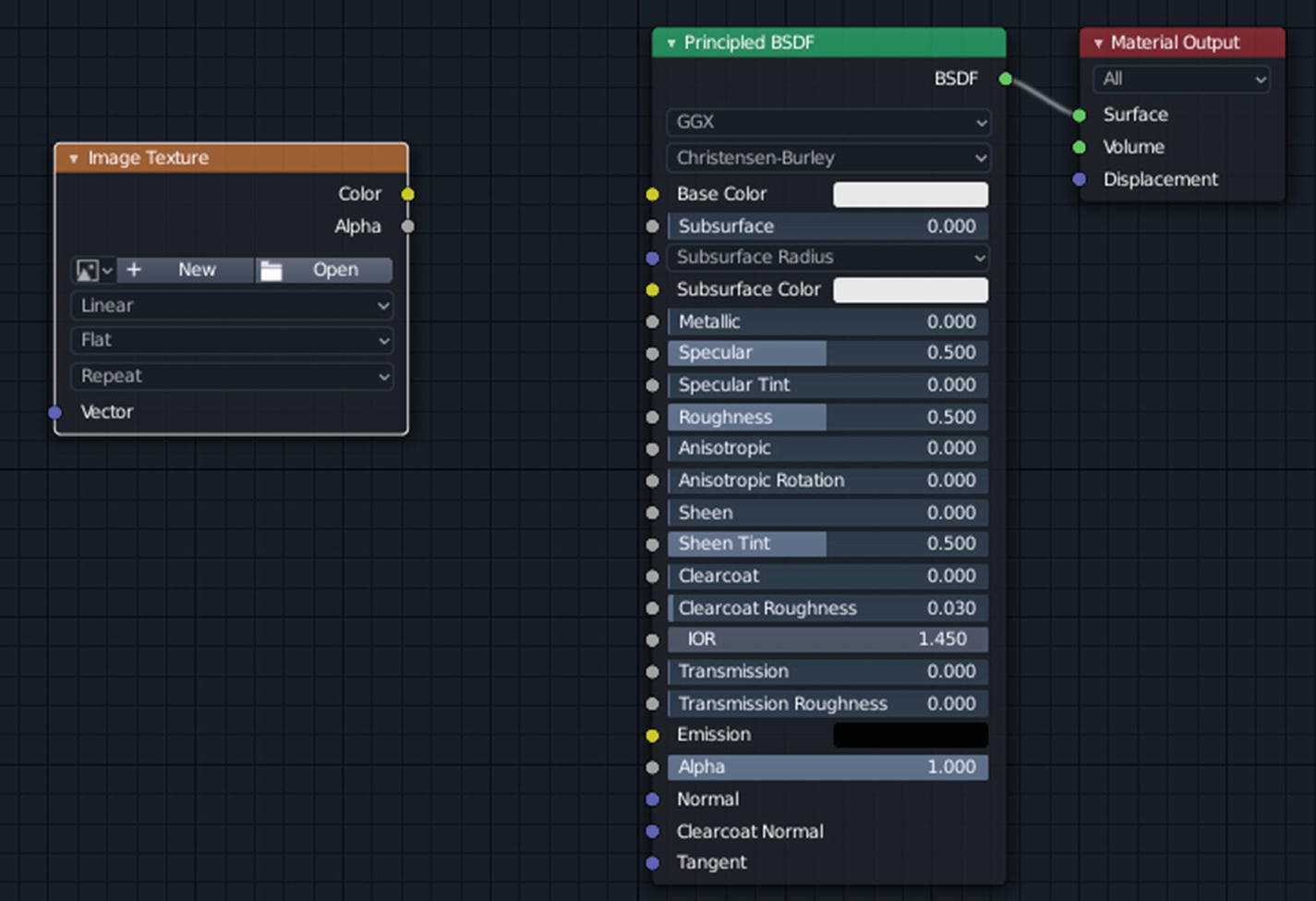
So, you are now ready to set up your material inside Blender. First, you need to import all the required textures. Press Shift+A to open the Add menu and then select Texture ➤ Image Texture. This will add the Image Texture node to your node tree, and in the Image Texture node there should be an option called Open. Click it to open the file browser (Figure 17-11).
Figure 17-11
Image Texture node in the tree
In the file browser, navigate to where you have exported your textures. The first one that we are going to import is the Diffuse map. Select it and choose Open Image, and it will load into Blender. Now click and drag a connection from the output of the Image Texture node and connect it to the BaseColor input of the Principled BSDF node (Figure 17-12).
Figure 17-12
Connecting nodes
When the nodes are connected, the output from one node should be connected to the input of another node via a white connection. You need to connect other texture inputs in similar way.
Now duplicate the Image Texture node by selecting it and pressing Shift+D, or create a new one. If you duplicate the node, then your image input will already be populated by the Diffuse texture that you imported earlier. Click the X icon to remove it. Now you should have a clean node. Next import the Roughness map for the texture. Once it’s imported, you may connect it to the Roughness input of the Principled BSDF shader. We also need to change the color space of the Roughness map. To do that, click the drop-down menu in front of Color Space; by default, it should be set to sRGB. Change it to Non-Color.
Now we need to import the metalness map. For that, follow the same steps again. Either create a new node or copy the previous one and delete the unwanted image. Once the image has been imported, we will change its color space to Non-Color as well. Then connect the output to the input of Metallic of Principled BSDF.
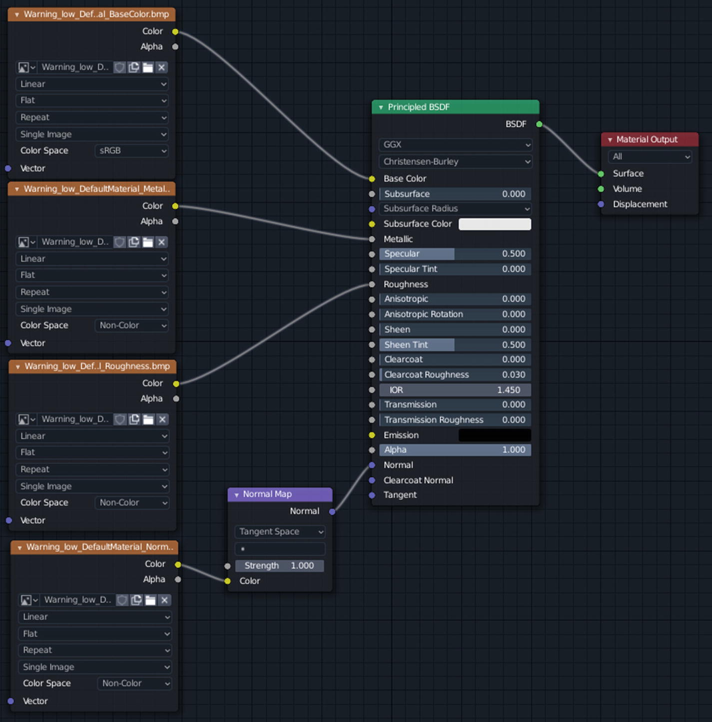
Lastly, we will import the normal map and change its color space to Non-Color as well. Also, we need to create a Normal Map node. The output of the Image Texture node containing the normal map will connect to the input of the normal map node, and then the output of the normal map node will connect with the Normal input of Principled BSDF node. The setup so far should look something like Figure 17-13.
Figure 17-13
Node setup
This should be good enough for creating a render of your mesh in Blender. Even though this is a quick and dirty setup, this still gets the job done pretty well. If you want, you can create more complex node setups that allow you to modify the textures beyond what is already created.
For a quick render setup, create a Sun lamp by pressing Shift+A in the 3D viewport and selecting Light ➤ Sun (Figure 17-14).
Figure 17-14
Adding a Sun lamp to a scene
Then raise it up and rotate it to an angle and also increase the intensity of Sun to 7 from the properties editor. Make the color of the sun slightly yellowish.
Now create a large ground plane and apply a white, slightly shiny material to it. If done correctly, your scene will be ready for rendering. You can also render without a camera by pressing the Z key and switch to the rendered view. This will initiate viewport rendering, but this does not produce good-quality renders. The best way to render is by using a camera.
Create a camera and then move and rotate it to align it the way you want. Then either press F12 on keyboard, which is the shortcut key for rendering, or click the Render button and click Render Image (Figure 17-15).
Figure 17-15
Render Image option
For the best render results, you can increase the render samples of the camera from the Scene properties in the properties editor (Figure 17-16). You will probably need several thousand samples and pretty powerful PC for rendering decently complex scenes in a reasonable time.
Figure 17-16
Scene properties
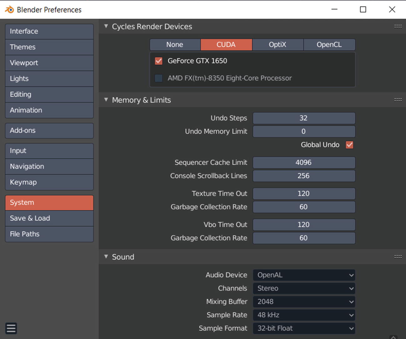
But before you render, you can change a few settings to help increase the render speed. First go to Edit ➤ Preferences ➤ System and at the top of the window there should be the option Cycles Render Devices. By default it should be set to None, but if you have a Nvidia GPU, set it to CUDA, or if you have AMD GPU, then set it to OpenCL (Figure 17-17).
Figure 17-17
Changing the Cycles render device
Then save your preferences.
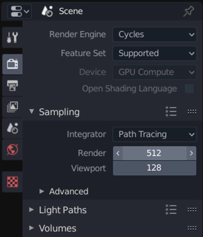
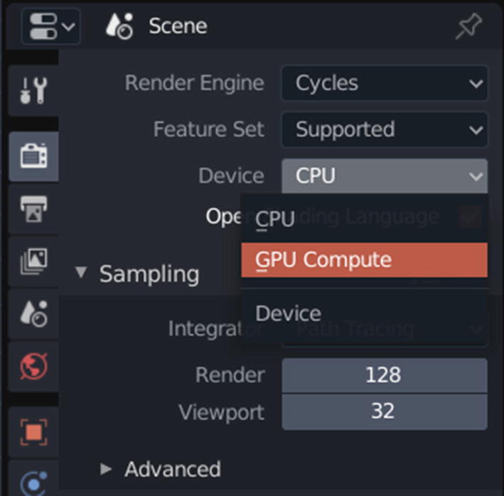
If you look at the Scene properties now, you should see the Devices option is now active. By default it should be set to CPU. Click it and change it to GPU Compute (Figure 17-18).
Figure 17-18
Changing the render device
The computation of the GPU is always faster if you have a high-performing graphics card. Also, if you look at the Sampling section, these options are currently set to the default values that are more or less preview values. The viewport samples will increase the render iterations when switching to Rendering mode in the viewport, while the render samples will increase render iterations when rendering with a camera.
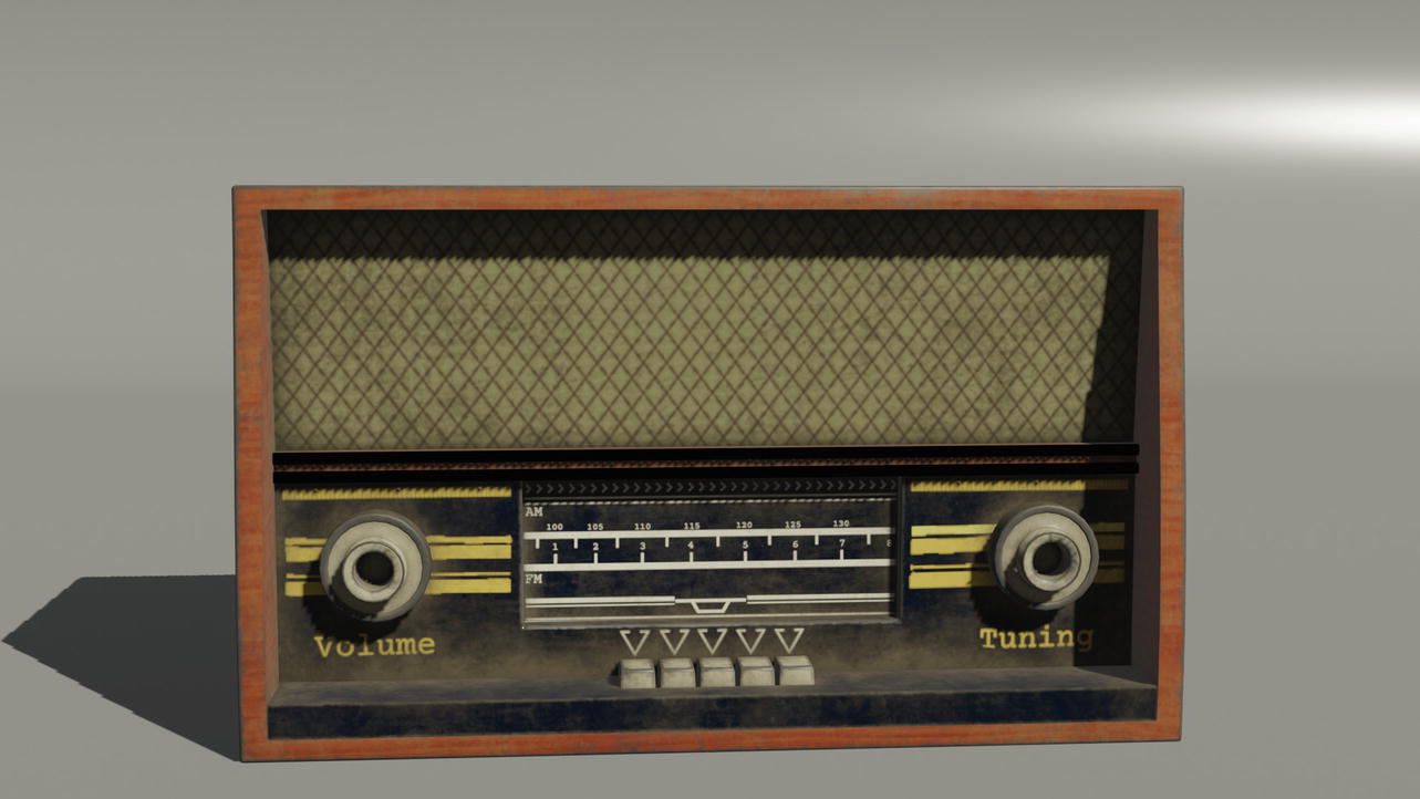
A higher value for Sampling will result in better render results but a longer compute duration (Figure 17-19).
Figure 17-19
Render created in Blender
Integration with Maya
Now let’s see how to use Substance Painter maps with Maya. For this project, we will use the Arnold 5 renderer. Arnold 5 is a physically based ray tracing render engine that ships with Maya and is used for creating high-quality renders for movies (Figure 17-20).
Figure 17-20
3D model into Maya
So, as you can tell, it is a powerful render engine that is used in a production environment. You will learn how you can use it to create renders for you.
Let’s bring in a mesh by dragging it from a folder and dropping it into the viewport of Maya (Figure 17-21).
Figure 17-21
Imported model in Maya
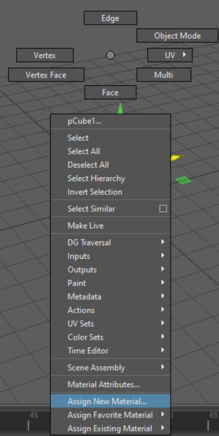
First, you need to apply an Arnold material to the mesh. To do that, select your mesh and right-click. In the menu that appears, scroll down and select Assign New Material (Figure 17-22).
Figure 17-22
Assigning a new material
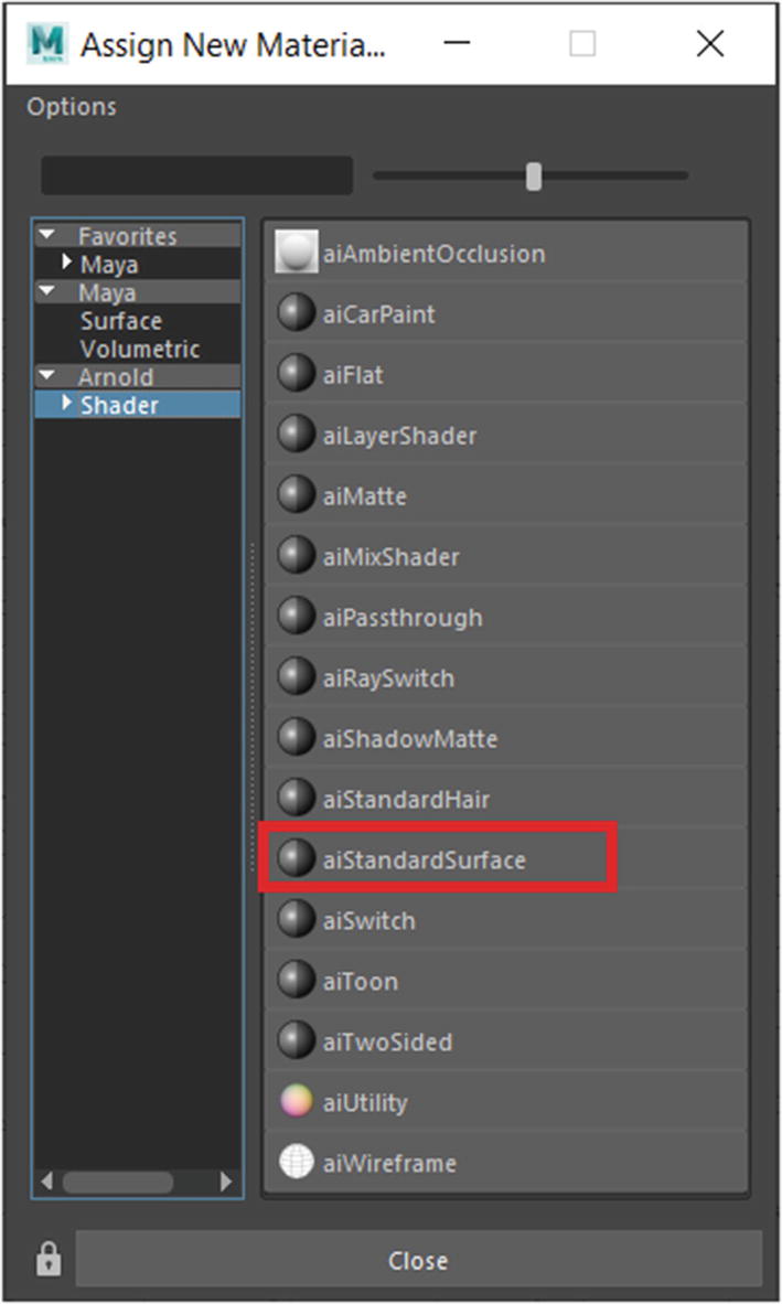
A new window should open asking you which material you want to apply to your mesh. Click Shader under the Arnold heading, and from the shader list on the right, choose aiStandardSurface (Figure 17-23).
Figure 17-23
Applying the aiStandardSurface shader
After you have applied the shader, then some new parameters should appear in the attribute editor (Figure 17-24).
Figure 17-24
Attribute editor
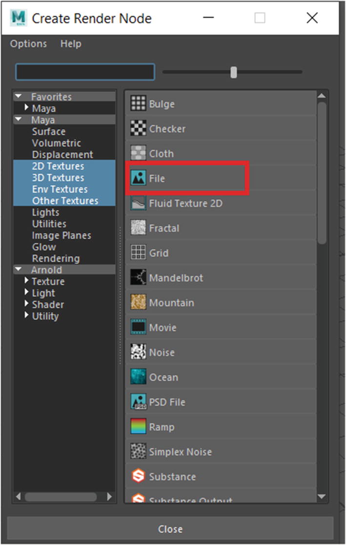
We need to plug in our maps in the texture slots present in the attribute editor. So, let’s begin with the base color. Click the small checkered square in the Color input. This should launch a new window called Create Render Node. Choose File from the list of options available (Figure 17-25).
Figure 17-25
Create Render Node window
Once you choose File, you will notice that the attribute editor changes. You’ll see some file attributes that you will work with (Figure 17-26).
Figure 17-26
File attributes
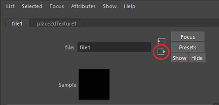
Click the folder icon toward the right of Image Name. This will launch the file browser. Navigate to your BaseColor map and click Open. This will load in the texture map into Maya. To go back to the attribute editor with texture inputs, click the button highlighted by the red circle in Figure 17-27.
Figure 17-27
Going back to the attribute editor
You may not be able to see the effect of the BaseColor map that you applied to the mesh. This is because by default the texture display is turned off. You can enable the texture display by pressing 6 on your alphanumeric keypad.
Now let’s import the other maps. On the Base tab there is a Metalness input. Click the small white check box next to the Metalness input. This will again open the Create Render Node window, where you should choose File. Once again, your attribute editor will change. Click the small folder icon next to Image Name, and this will launch the file browser. Choose the metallic map and click Open. This will load the metallic map into Maya. Once you’re done, click the drop-down menu next to Color Space. By default it should be set to sRGB, so choose RAW from the list (Figure 17-28).
Figure 17-28
Changing the color space of the map
Once that’s done, go back to the attribute editor with the image inputs. You will import the Roughness map next. The Roughness map needs to be imported into the Roughness input under the Specular heading (Figure 17-29).
Figure 17-29
Roughness input
Once again, click the small checkered box and do exactly what you have been doing for the past couple of textures. Choose File in the Create Render Node window. Then in the new editor, click the small folder icon, and in the file browser window navigate to your Roughness map and click Open to import the image into Maya. Now change Color Space to RAW for this as well, and you are done.
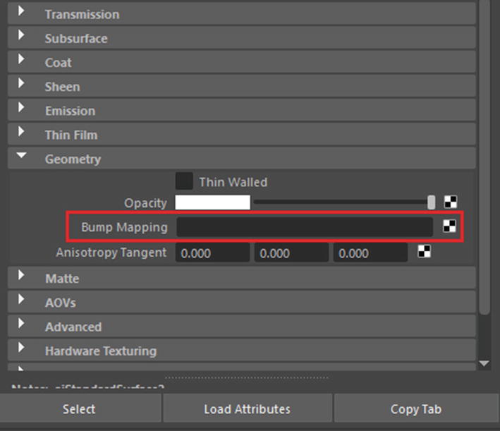
Now let’s import the normal map. This will be slightly different from others that you have imported so far. First, you will find the normal map under the Geometry item; it is named Bump Mapping (Figure 17-30).
Figure 17-30
Bump Mapping input
Click the small checkered box and choose File. This will change the attribute editor into the Bump2D window. Click the drop-down menu next to where it says Use As. By default, it is set to Bump, but for our case we will change it to Tangent Space Normals (Figure 17-31).
Figure 17-31
Changing the use type
Now click the black box with the arrow next to Bump Value; this will take you to the file selection. Again, click the familiar folder icon, and that will open the file browser. Navigate to the normal map that you want to import. Then after selecting it, click Open. This will load your normal map; once again, change its color space to RAW. Now your normal map has been set up as well. Go back to the editor with texture inputs.
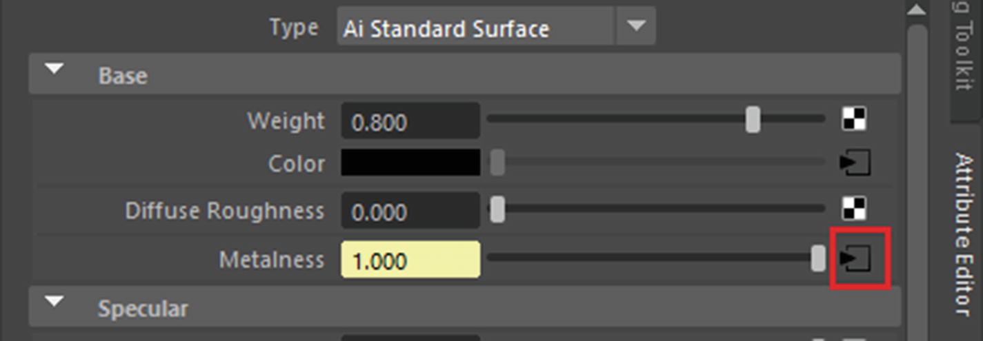
Before you render, you need to change one more thing. Click the box with the arrow icon next to the Metalness input (see Figure 17-32).
Figure 17-32
Metalness icon
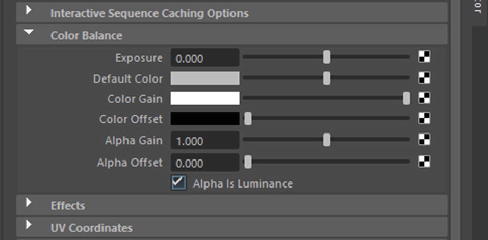
Now expand the Color Balance heading and look for Alpha Is Luminance. Select this box to activate it (Figure 17-33).
Figure 17-33
Alpha Is Luminance box
Do the same for the Roughness map. After that, your file is ready for rendering. A simple setup can be similar to what you used in Blender. There is a large ground plane and some Arnold lights.
To do this, click the Arnold tab on the Shelf of Maya (Figure 17-34).
Figure 17-34
Shelf of Maya
You can either create a couple of Area lights (first icon on the left) and try adjusting their parameters to achieve the desired lighting or create a SkyDome light (fourth icon from the left) to create an HDRI-based lighting environment. If you have good-quality HDRI images, then you can create light quickly. For our case, we will create a SkyDome light; you can get some free high-quality HDRI images from Hdrihaven.com. Once you have downloaded an HDRI image that you like, you can click the small checkered square next to Color in the SkyDomeLight attributes window and choose Image from the list. In the new window that appears, click the small folder icon next to File Name, and file browser window will open. From there, navigate to your HDRI image file and load it into Maya. This will apply the texture to the SkyDome light. Your SkyDome light should now appear textured with the HDRI image that you applied to it (Figure 17-35).
Figure 17-35
The scene with the HDRI SkyDome light
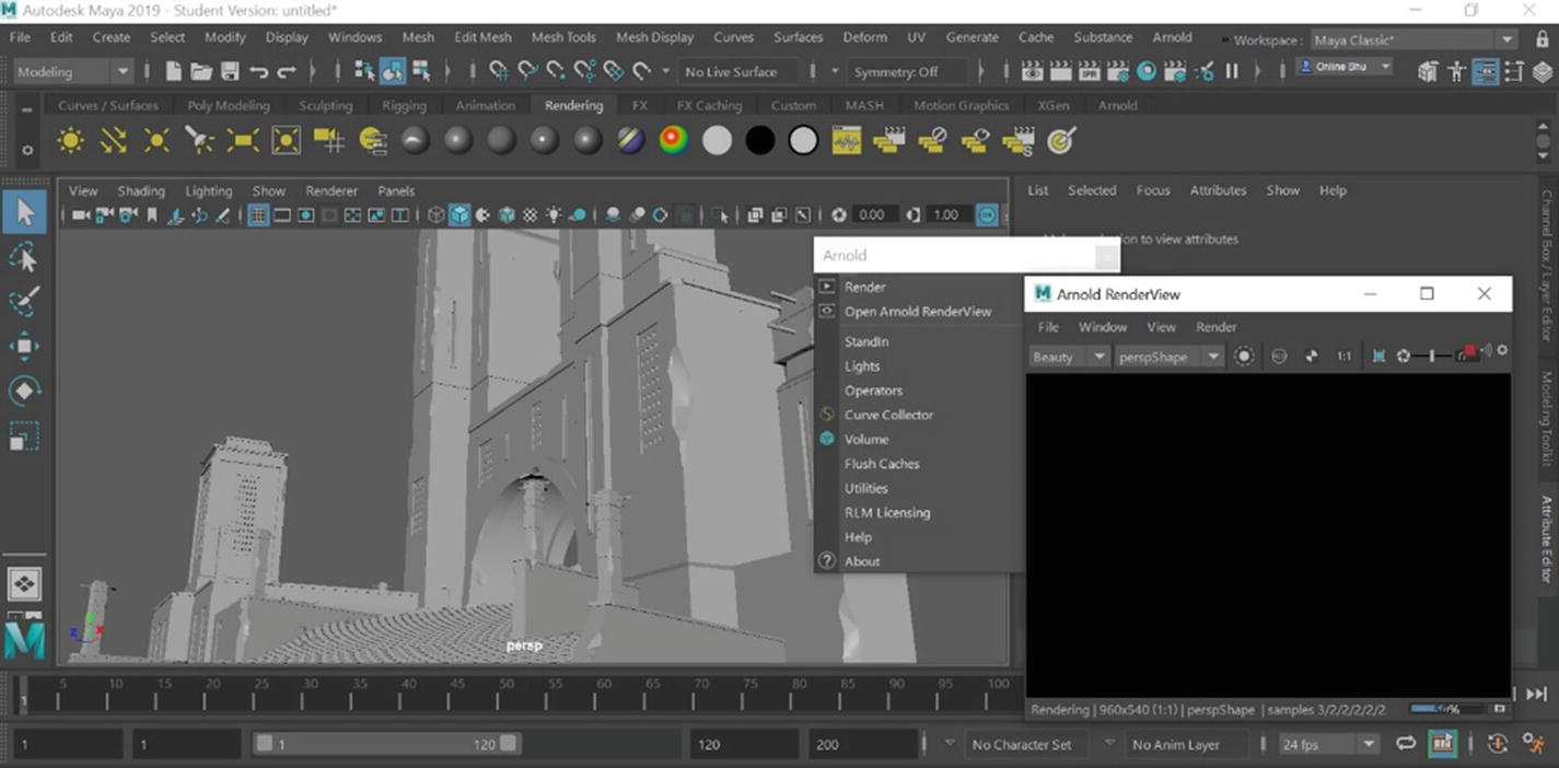
Your scene is ready for rendering now. Click the Arnold tab in the menu bar and click Render (Figure 17-36).
Figure 17-36
Rendering the scene
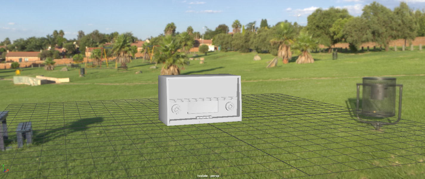
Note that your scene will render from the view camera that you are using to view your scene. So, set your angle first so that you are properly viewing your model (Figure 17-37).
Figure 17-37
Final render in Maya
Integration with Marmoset Toolbag
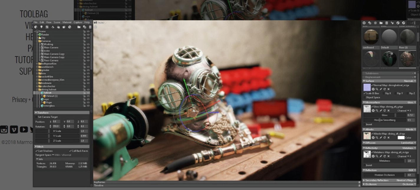
You already exported your textures for Marmoset Toolbag in a previous chapter, so now all that remains is to import those textures into Marmoset. First, we will be using the latest version of the software, which currently is Marmoset Toolbag 3 (Figure 17-38).
Marmoset is a dedicated real-time rendering, animation, and baking program, but it is primarily used by artists to create portfolio-ready renders by using its powerful real-time render engine. We are going to do the same, so let’s launch Marmoset Toolbag 3 and start working.
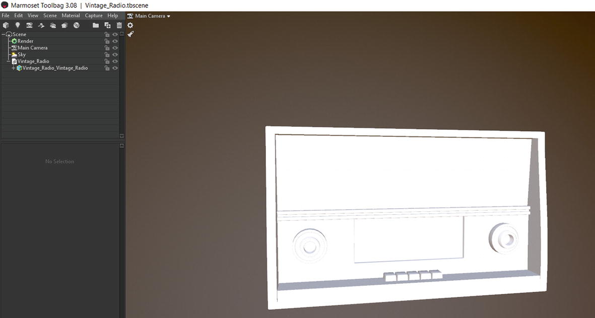
You will import your test mesh by dragging and dropping it onto the interface of Marmoset Toolbag (Figure 17-39).
Figure 17-39
File when imported into Marmoset Toolbag
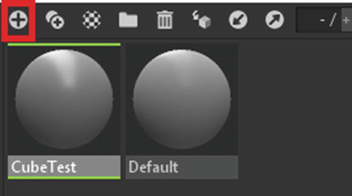
Now create a new material by clicking the button shown in Figure 17-40.
Figure 17-40
Creating a new material
Name it CubeTest.
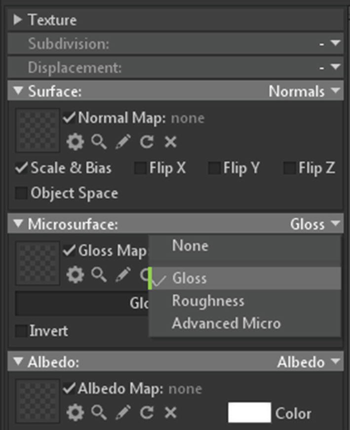
Doing that will place the mesh in the center of the screen. Now, before you bring in the textures, you will change a few things. Now change Microsurface from Roughness to Glossiness (Figure 17-41).
Figure 17-41
Changing the input type
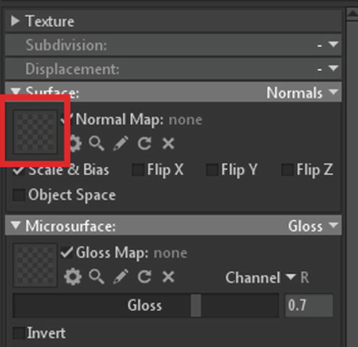
Change Reflectivity from Metalness to Specular. Now you are ready to import. To import, click the checkered icon to launch the file browser (Figure 17-42).
Figure 17-42
Checkered map button for importing a texture map
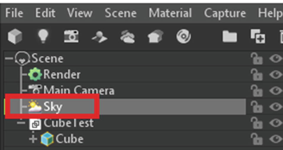
You need to import the correct texture maps into the correct slots like this. Then drag and drop the material from the tray to the cube. Immediately you will see the effect of your texture. There is no waiting for rendering as everything is in real time. You can change some settings to get the render that you want. You can change the sky settings by clicking Sky in the outliner (Figure 17-43).
Figure 17-43
Selecting Sky from the outliner
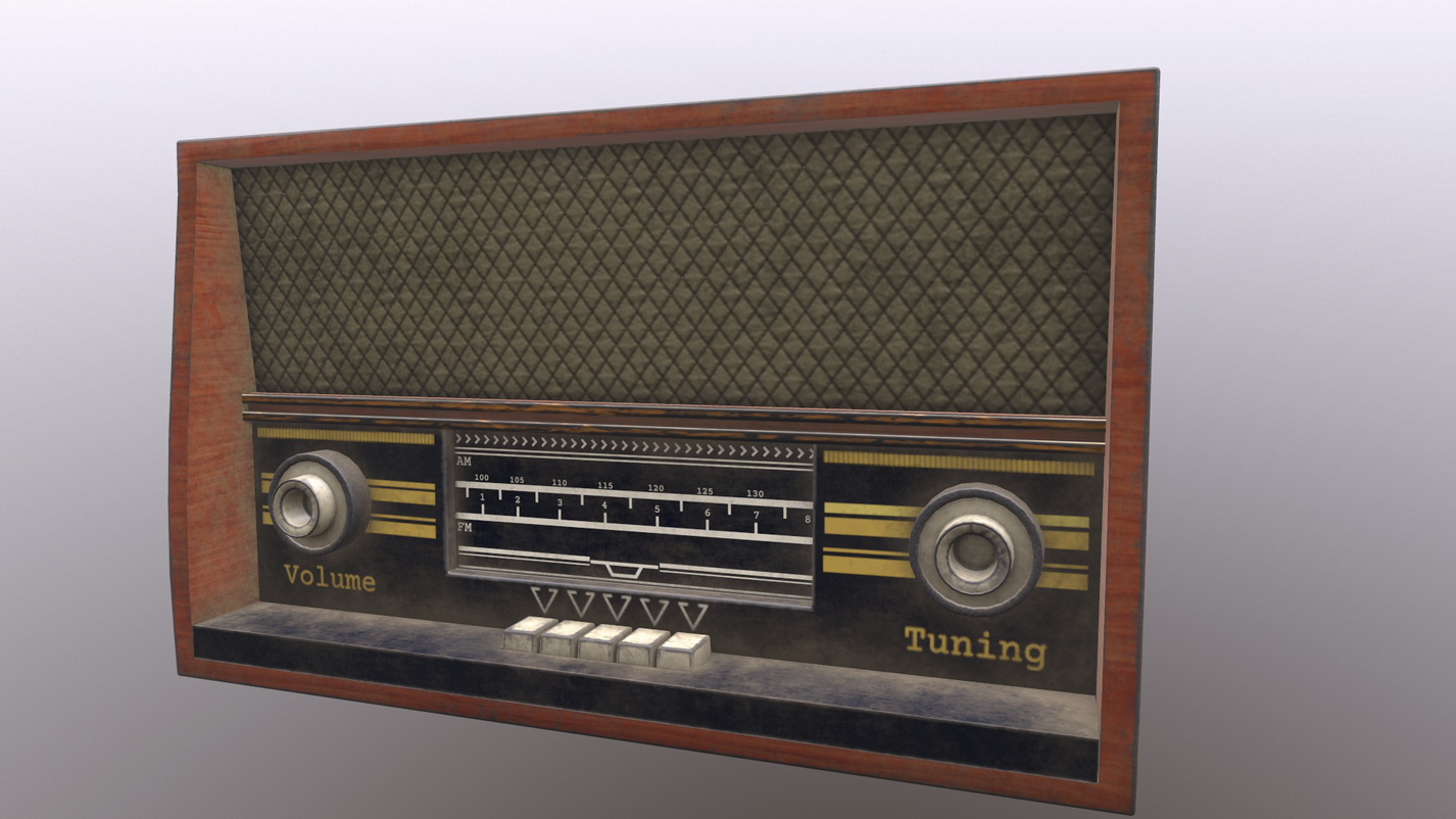
Now click Presets to choose from a list of available skies for the lighting environment. After you are satisfied, you can press F11 to save a render (Figure 17-44).
Figure 17-44
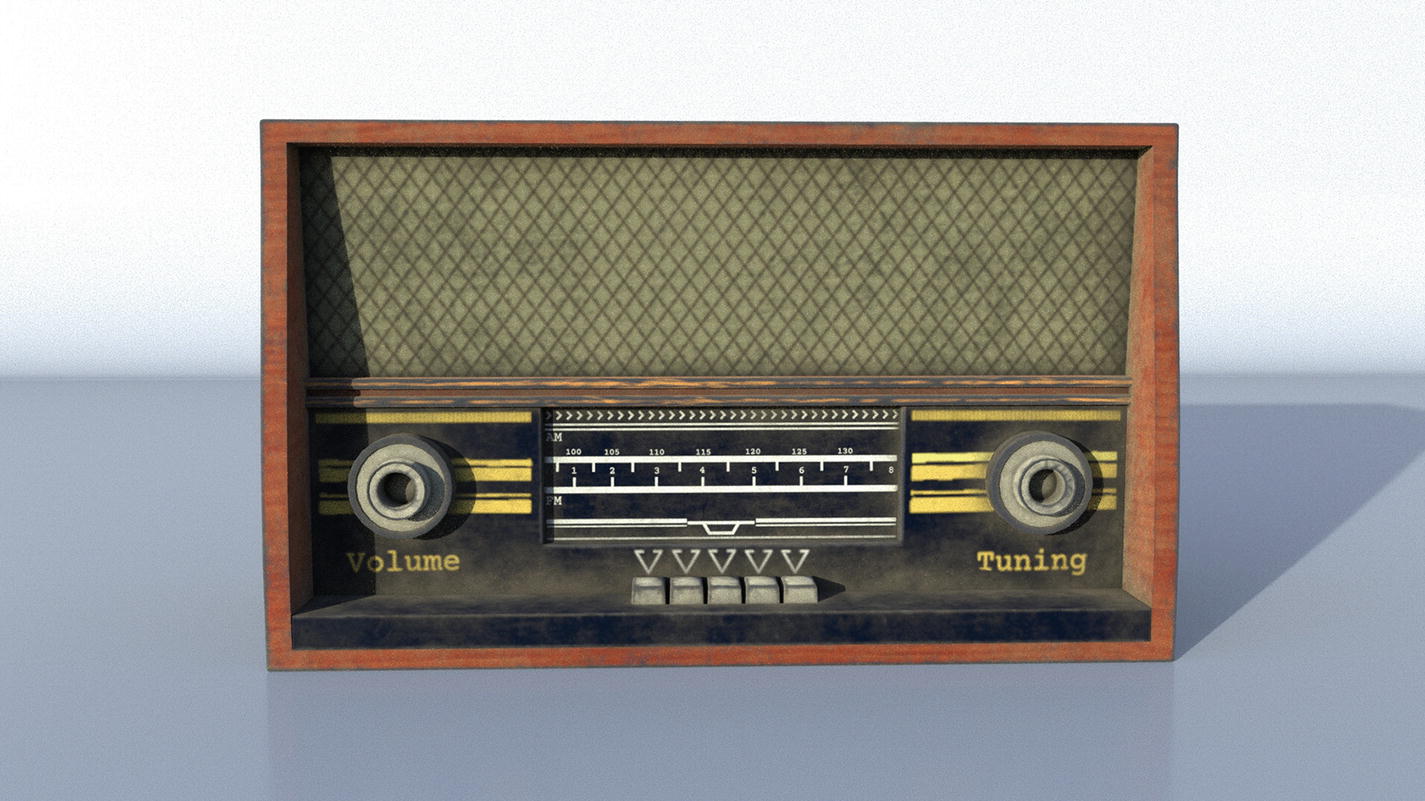
Final render from Marmoset Toolbag
You should now have a clear understanding of how to use the setup render in Blender, Maya, and Marmoset Toolbag.
In the next chapter, you will learn about the process of exporting materials for the game engine.