
5
A School of Robotic Fish for Pollution Detection in Port
Huosheng Hu, John Oyekan, and Dongbing Gu
University of Essex Colchester, UK
CONTENTS
5.3 Biologically Inspired Design
5.4 Layered Control Architecture
5.5 Robotic Fish for Pollution Detection at Port
Abstract
Natural selection has made fish beautiful swimmers with high efficiency and perfect maneuvering abilities No man-made aquatic systems are currently able to match such performance To build a robot to realize fish-like propulsion and maneuvering abilities requires a full understanding of fish muscle structure, hydrodynamics, and how to mimic. This chapter overviews the robotic fish research at Essex, which is focused on the biologically inspired design of autonomous robotic fish as well as their applications to pollution detection in port. Our efforts and experience in building a number of generations of robotic fishes to navigate in a three-dimensional unstructured environment are described, including the successful launch of an EU FP7 project SHOAL since March 2009 Finally, a brief summary and future research directions are outlined.
5.1 Introduction
In nature, fish propel themselves by bending their bodies and/or using their fins and have gained astonishing swim and maneuvering abilities after thousands years of evolution For instance, the tuna swims with high speed and high efficiency, the pike accelerates in a flash, and the eel can swim skillfully into narrow holes This has inspired many robotics researchers to build new types of aquatic man-made systems, namely, robotic fish. Instead of the conventional rotary propeller used in ships or underwater vehicles, a robotic fish relies on undulation or oscillatory movements to generate the main propulsion energy It is clear that this kind of propulsion is less noisy and more maneuverable than man-made underwater vehicles.
RoboTuna was the first robotic fish developed at the Massachusetts Institute of Technology in 1994 (Streitlien, Triantafyllou, and Triantafyllou 1996) to explore and understand the biology of aquatic creatures Since then, many kinds of robotic fishes have been developed worldwide. A robotic lamprey using shape memory alloy (SMA; Jalbert, Kashin, and Ayers 1995) was built at Northwestern University, with the aim to realize mine countermeasures. In Japan, a micro-robotic fish was developed at Nagoya University using an ionic conducting polymer film (ICPF) actuator (Guo et al. 1998) and Tokai University constructed a robotic Blackbass (Kato 2000) to research the propulsion of pectoral fins. The National Maritime Research Institute (NMRI) has developed many kinds of robotic fish prototypes, from PF300 to PPF-09, to exploit the effective swimming mode. Mitsubishi Heavy Industries built a robotic fish to mimic an extinct fish, namely, coelacanth (Yamamoto and Terada 2003). Most of the current robotic fish can only operate in the laboratory, swimming on the water surface, and are not robust enough for daily operation in the real world.
The Essex Robotics Research Group has worked on robotic fish research since 2003, aiming to design and build autonomous robotic fish that would have three major features: to (1) swim like a real fish; (2) realize autonomous navigation; and (3) be deployed in real-world applications (Liu and Hu 2010) Most important, the robotic fish we built should be able to swim in three dimensions within an unknown and dynamically changing environment and should be fully autonomous in daily operations. Also, it will be able to be deployed for real-world applications such as water pollution monitoring and security surveillance This chapter is focused on the biologically inspired design of our autonomous robotic fish; that is, how the basic fish swimming behaviors have been realized in our robotic fish, as well as its application to pollution detection in a seaport.
The rest of this chapter is organized as follows Inspired from nature, Section 5.2 describes fish swimming behaviors and their division in terms of propulsion mechanism and temporal features Section 5.3 presents the biologically inspired design of Essex robotic fish and Section 5.4 describes novel layered control architecture for the realization of fish swim behaviors in our robotic fish. Section 5.5 presents a brief introduction of our robotic fish used in pollution detection. Finally, a brief summary is presented in Section 5.6.
5.2 Inspired from Nature
Today, biological fish exhibit a large variety of swimming behaviors that are generated by undulatory or oscillatory movements of their body or fins, as shown in Figure 5.1. In general, fish swimming motion can be viewed from two different angles. One is propulsion mechanisms and another is temporal features. This has inspired robotics researchers to build robotic fish that can mimic the swimming behaviors of real fish.
In terms of propulsion mechanisms, some fish bend their bodies and/or caudal fins (BCF) and other fish use their median and/or paired fins (MPF). Both BCF and MPF propulsion can be further divided into undulatory and oscillatory propulsion. Four types of undulatory BCF propulsion (anguilli-form, subcarangiform, carangiform, thunniform) and one type of oscillatory BCF propulsion (ostraciiform) are shown in Figure 5.2 (Sfakiotakis, Lane, and Davies 1999). In undulatory BCF propulsion, the propulsive wave traverses the fish body in a direction opposite to the overall movement and at a speed greater than the overall swimming speed. Apart from caudal fins, some fish use more bodies to generate the propulsive wave and others use less bodies.
Anguilliform in Figure 5.2a is highly undulatory, and thunniform in Figure 5.2d is toward oscillatory. Subcarangiform in Figure 5.2b and caran-giform in Figure 5.2c are in between. Their wavelength, wave amplitude, and the way in which thrust is generated are all different For instance, the fish body shows large-amplitude undulation in anguilliform, but undulation decreased gradually from subcarangiform to carangiform to thunniform

FIGURE 5.1
Typical fin configuration of fish.

FIGURE 5.2
Fish with BCF propulsion.
The oscillatory BCF propulsion, which ostraciiform, is characterized by the pendulum oscillation of its stiff caudal fin. The fish body is essentially rigid, as shown in Figure 5.2e. On the other hand, both undulatory and oscillatory MPF propulsion are routinely adopted by many fish as auxiliary propul-sors for stabilization and maneuvering, although some fish may use them as main locomotion means at low speeds. The temporal features of fish swimming behaviors can be classified as:
• Steady/sustained swimming, which is characterized by a cyclic repetition of the propulsive movements for a long distance at a roughly constant speed
• Unsteady/transient swimming, which is typically for catching prey or avoiding predators, including fast starts, sharp turns, bursts, and escape maneuvers (Sfakiotakis, Lane, and Davies 1999).
Steady swimming behaviors of fish have been widely investigated by biologists, mathematicians, and robotics researchers. In fact, unsteady swimming behaviors of fish also play an important role in fish life, in which body movements are very significant and characterized by high accelerations. Some biologists have recently studied unsteady swimming motion of fish; for example, the kinematics of fish. It should be noticed that both steady and unsteady swimming behaviors of fish can be realized by BCF and MPF propulsions or their combination. This reflects the complexity of fish swimming movements (Drucker and Lauder 2002).
To mimic fish swimming abilities, current robotic fish projects have been focused on three aspects: (1) fish locomotion and hydrodynamics, (2) arti-ficial muscle technologies, and (3) sensor-based control mechanisms. Most researchers have worked on one of these aspects Man-made ships and underwater vehicles are based on steady-state hydrodynamics for the high stability and high loading capability and are unable to match the turning and maneuvering capability of real fish. Therefore, the construction of the robotic fish relies on a full understanding of undulatory or oscillatory movements of real fish, corresponding hydrodynamics, new materials, and advanced control mechanisms.
Different from most previous research, we focus on two levels of complexity of fish locomotion systems; that is, swimming patterns for propulsion and multiple behaviors for temperate features Layered control architecture has been developed at Essex by Liu, Hu, and Gu (2006) to realize fish-like swimming behaviors, especially unsteady behaviors such as sharp turning and fast starts. Our research has focused on undulatory BCF propulsion, that is, carangiform, in order to realize it in our robotic fish and study its advantages in the engineering field. Other types of BCF and MPF will be investigated gradually in our future research.
5.3 Biologically Inspired Design
We have built a number of generations of robotic fishes at Essex. Figure 5.3 shows six generations. In general, these robotic fish are about 50 cm long and have three or four powerful R/C servo motors and 2 DC motors. Servo motors are concatenated together in the tail to act as joints, as shown in Figure 5.4. Additionally, one DC motor is fixed in the head to change center of gravity of the fish for diving and another DC motor controls the micropump. On the back of the fish body, a dorsal fin is fixed vertically to keep the fish from swaying. The high quality of the servo motors and the very soft structure of the tail make it possible for the robotic fish to bend its body at a large angle in a short time, which is novel, and nobody, as far as we know, has done this before us Each robotic fish has over ten embedded sensors: one gyroscope, one pressure sensor, two position sensors, two current sensors, one voltmeter, four infrared sensors, and one inclinometer These embedded sensors enable the fish to detect its depth, the yaw/roll/pitch angle of its body, and the distance to the obstacle in front of it Additionally, the servo position and current consumption information can be obtained Bluetooth and RS232 serial ports are used to communicate with an external PC, which is used to program Gumstix and peripheral interface controller (PIC) and collect the sensor log. Figure 5.5 shows one of the Essex robotic fish that operated in the London Aquarium in 2005. The fish demonstrated an extremely fish-like motion and attracted much attention worldwide.
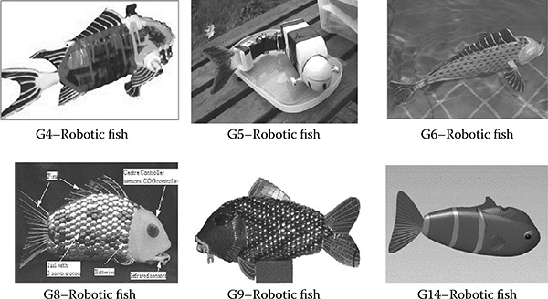
FIGURE 5.3
Robotic fish built at Essex (G means generation).

FIGURE 5.4
Configuration of Essex robotic fish.
5.4 Layered Control Architecture
Figure 5.6 presents the layered control architecture for our robotic fish, which consists of three layers: the cognitive layer, behavior layer, and swim pattern layer (Liu, Hu, and Gu 2006). Compared with traditional plan-based approaches, it has the advantages of easy design, fast response, and robustness. The swim pattern layer is particularly designed for the special propulsion feature of the robotic fish. In the behavior layer, states and actions are directly related to the robot physical sensors and swim patterns. In the cognitive layer, states related to high-level activities are abstracted and used to direct the behavior coordination in the behavior layer.
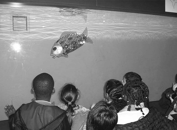
FIGURE 5.5
Essex robotic fish operated in the London Aquarium.
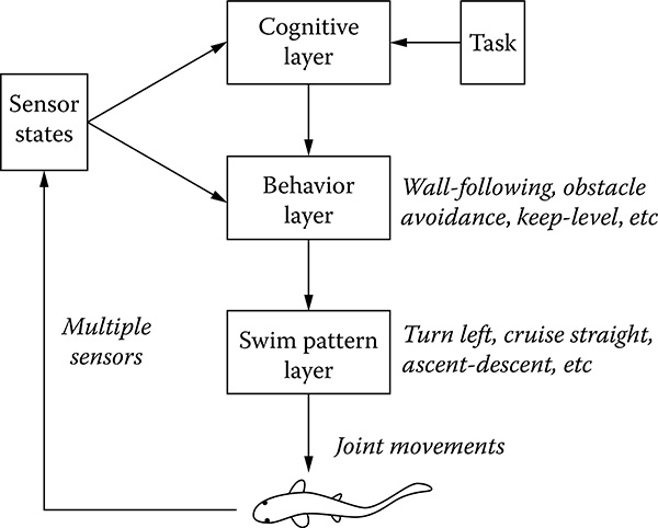
FIGURE 5.6
Layered control architecture.
Within this layered architecture, parameter optimization can be conducted separately at each layer. For instance, in the swim pattern layer, each swim pattern is optimized to achieve the best performance. In the behavior layer, behaviors are optimized according to the encoding method of behaviors. If behaviors are encoded by fuzzy logic controllers, fuzzy rulers and fuzzy function parameters will be optimized In the cognitive layer, optimization also could be designed for the parameters of reasoning and planning tasks (Liu, Hu, and Gu 2006).
5.4.1 Cognitive Layer
The cognitive layer extracts the robotic fish status from the sensor states and then performs task-oriented reasoning and planning It makes decisions on how to coordinate fish behaviors to achieve a given task. Rather than providing a detailed objective for the behavior layer, for example, a particular trajectory for the robotic fish to follow, the cognitive layer adjusts the contribution weights of individual behaviors for the emergent behavior In addition, the cognitive layer will adjust the parameters for some individual behaviors, such as the depth level for keep-level behaviors
In a known environment with available models, planning can be done offline, and solutions can be found and evaluated prior to execution. However, in dynamically changing environments, models and policies need to be adaptively revised online at this layer Trial-and-error processes are normally carried out. As can be seen from Figure 5.6, the raw sensor data are converted into sensor states so that individual behaviors take sensor states as stimulus and calculate responses concurrently The cognitive layer extracts the abstracted states from the sensor states The parameters for behavior coordination are transferred into the behavior layer after reasoning and planning.
5.4.2 Behavior Layer
The behavior layer is located in the middle of the proposed layered control architecture for the reactive control of our robotic fish. It firstly converts the sensor raw data into sensory states by fuzzy membership functions and then inputs these states into individual behaviors Fuzzy logic controllers are designed for individual behaviors to process these states The responses of all behaviors are coordinated together by the behavior coordination function, which is defined by the parameters from the output of the cognitive layer The subsumption architecture is adopted for this layer because of its simplicity Here the stimulus is the sensor states and the response is the action. Stimulus-response (SR) diagrams (Arkin 1998) are used for the design of specific behavioral configurations. Eight behaviors are designed for the generic purpose in this layer, namely:
1 Avoid obstacles behavior to avoid both stationary and moving objects based on infrared (IR) sensors The possible action is selected from all swim patterns.
2. Follow-wall behavior to keep the robotic fish at a certain distance from the wall based on the information gathered by IR sensors The possible actions are cruise straight, cruise in left/right turn.
3. Wander behavior to explore the tank randomly. No sensor states are necessary. Possible actions include cruise straight, cruise in left/ right turn, and ascend/descend.
4. Keep-level behavior to keep the robotic fish swimming at a desired depth level specified by the cognitive layer. It monitors the pressure sensor data and controls whether the fish ascend or descend.
5. Seek-goal behavior to direct the robotic fish to swim toward the goal; the possible actions are cruise straight and cruise in right turn.
6. Noise behavior using a random swim pattern to avoid the local minima and go out from a trap situation by trying all kinds of swim patterns.
7. Feed behavior for a robotic fish to return to a charging station when its battery is low.
8 Rescue behavior for emergency and self-protection action when robotic fish face unexpected situations such as motors malfunction, extreme high internal temperature, etc.
The behavior layer not only decides which swim pattern will be selected next but adjusts some key parameters for the selected swim pattern Each swim pattern has tens of parameters in its function to specify its performance However, to simplify the control loop, the behavior layer only adjusts two parameters. More details can be found in Liu and Hu (2010).
5.4.3 Swim Pattern Layer
Our project aims to design and build an autonomous navigation robotic fish that would swim like a real fish and realize autonomous navigation. To realize the fish-like motion, we have designed three or four tail joints for our robotic fish. The added-mass hydrodynamic theory is adopted here to achieve seven fish-like swim patterns as follows.
1. Cruise straight: The fish swims along a straight line at a constant speed, possibly with small acceleration/deceleration.
2. Cruise in turning: Fish is turning in a small angle and at a constant speed.
3. Burst: The fish shows sudden straight acceleration; that is, cyclic fast undulation. The burst-and-coast swim pattern is commonly used in fish life for energy savings expected up to 50%.
4. Sharp turn : Generates a sudden angular acceleration for avoiding predators or obstacles, including two types: C-shaped and S-shaped.
5. Brake: The fish generates a sudden straight deceleration by its special tail motion, usually in combination with pectoral and pelvic fins.
6. Coast: A kind of motion in which the fish body is kept motionless and straight
7. Ascend-descend: A kind of motion in which a robotic fish can change its depth in water
A detailed description of these swimming patterns can be found in Hu et al. (2006). Here we only explain two swimming patterns for simplicity.
The motion of the fish tail in cruise straight could be described by a traveling wave shown in Equation (5.1), which was originally suggested by Lighthill (1960). Its original point is set at the conjunction point between the fish head and its tail. The parameter vector E = {c1, c2, k, ω} is the key element to determine the kinematics of the fish tail.
(5.1)
where ybody is transverse displacement of a tail unit; X is displacement along the main axis; k = 2π/λ is the wave number; À is the wavelength; c1 is the linear wave amplitude envelope; c2 is the quadratic wave amplitude envelope; co = 2nf is wave frequency; f is the oscillating frequency of the tail; and t is time.
The sharp turn sequence includes the shrink stage, in which the tail bends to one side very quickly, and the release stage, in which the tail unbends in a relatively slow speed from the middle section of the body to the tail tip (Liu and Hu 2004) A circle function shown in Equation (5.2) is deployed to describe the joint-end trajectory, which is tangential to the x-axis. The center of the circle changes with respect to time.
(5.2)
where
where cxi,cyi,ti,(i = 1,2,3),k are parameters to decide the feature of the sharp turn swim pattern such as shape, bending speed, maximum bending angle, etc
5.5 Robotic Fish for Pollution Detection at Port
5.5.1 System Configuration
Funded by the European Union FP7 grant, the SHOAL project (Search and monitoring of Harmful contaminants Other pollutants And Leaks in vessels in part using a swarm of robotic fish) aims to design and create advanced robotic fish that are able to navigate the port environment autonomously. These robotic fish will be fitted with underwater communications in order to communicate with each other and broadcast their information to the shoreline. They will be fitted with chemical sensors in order to detect different pollutants in the water, and they will have embedded intelligence allowing them to search and monitor pollution as a swarm.
To develop a technique to control the robotic fish swarm for their sensors to monitor a port environment, we face some technical challenges The first challenge is how to quickly find the source of pollutant, and the second challenge is how to effectively control the agents so that collision between them is avoided. Researchers have been investigating various approaches to provide coverage to the environment This includes the use of deterministic approaches such as multispanning trees for multiple robots and cellular decomposition (Gabriely and Rimon 2001; Zheng et al. 2005). However, it has been proven that the performance of deterministic approaches approaches that of stochastic approaches in the presence of noise from the environment (Balch 2000; Nikolaus and Alcherio 2007).
Figure 5.7 shows the general architecture of the SHOAL system being developed by the SHOAL consortium. A swarm of robotic fish will be built at Essex and communicated through an underwater sonar system developed by the project partner, Thales Safare in France. Robotic fish receive the signals from a network of four pingers in order to calculate their position. When a robotic fish is surfacing, it is able to receive a Global Positioning System (GPS) signal from satellites to update its position and its clock.
Figure 5.8 presents the control software architecture for SHOAL robotic fish. As can be seen, it has three layers and is based on the layered control architecture shown in Figure 5.6. The addition of three modules, such as chemical analysis, underwater sonar communication, and a three-dimensional map, is to implement the pollution monitoring tasks as well as pollution mapping. The hardware configuration of the control system for SHOAL robotic fish is shown in Figure 5.9, in which two small Gumstix PCs with a Linux operating system are deployed The design of a SHOAL-1 robotic fish, which is about 80 cm long and 30 cm high, is presented in Figure 5.10. It was displayed at the Science Museum in London between June 2010 and February 2011

FIGURE 5.7
Description of EU SHOAL project.
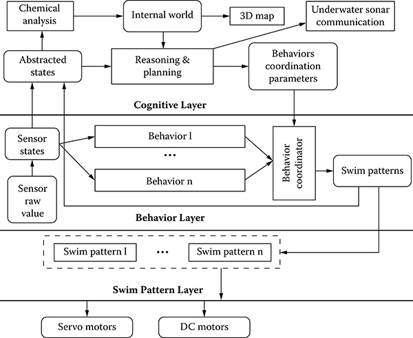
FIGURE 5.8
Control software architecture for SHOAL robotic fish.
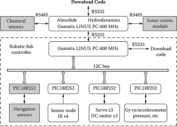
FIGURE 5.9
Hardware configuration of SHOAL robotic fish.
5.5.2 Bio-Inspired Coverage of Pollutants
We have developed a novel bacterial chemotaxis algorithm to find the source of the pollution in a port. A flocking algorithm is deployed to position the robotic fish optimally, avoid collisions, and ensure group foraging. The key idea is to place our robotic fish in a port environment based upon the density profile of the pollutant to be monitored so that areas of high environmental pollutant concentration receive more attention than areas of low pollutant concentration In this way, densely polluted areas are monitored more close than the sparsely polluted areas, which is computationally efficient and cost-effective.
A bacterium chemotaxis motion is composed of a combination of tumble and run phases The frequency of these phases depends on the measured concentration gradient in the surrounding environment The run phase is generally a straight line, whereas the tumble phase is a random change in direction with a mean of about 68 degrees in the Escherichia coli bacterium. If the bacterium is moving up a favorable gradient, it tumbles less, thereby increasing the length of the run phase and vice versa if going down an unfavorable gradient. This behavior was modeled by Berg and Brown by fitting the results of their experimental observations in Brown and Berg (1974) with a best fit equation in Berg and Brown (1972). This model is shown below:
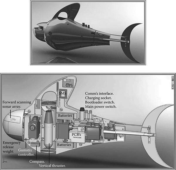
FIGURE 5.10
SHOAL fish for pollution detection: (a) run length = 2 and (b) run length = 30.
(5.3)
(5.4)
xíPb where t is the mean run length and T0 is the mean run length in the absence of concentration gradients, a is a constant of the system based on the chemotaxis sensitivity factor of the bacteria, and Pb is the fraction of the receptor bound at concentration C. In this work, C is taken as the present reading taken by the robotic agent. kd is the dissociation constant of the bacterial chemoreceptor, and dPh/dt is the rate of change of Pb.
The following modified flocking controller is used to realize the flocking control for agent x{ .
(5.5)
where D(t) = |x¡ (t) - Xj (t) ; B = H(x{(t) - xh(t)); xh(t) is the position of the agent with the highest measurement in the neighborhood of x{ . The neighborhood is determined by the communication radius of each robot agent K > 0 is the magnitude of the repulsion force between agent xi and agent Xj. Constant H is the attractant gain for the force between agent x{ and the agent xh with the highest environmental quantity measurement in the neighborhood
The two behaviors are then combined and the new position of the agent xi calculated using x{:
(5.6)
where both constants F = 0.01 and B = 0.94 are gains for the flocking and the bacteria behavior, respectively
Before combining the two behaviors together, the bacterial chemotaxis controller was subjected to tests using two metrics of environmental explo-ration and source convergence Fifty robots were used in our simulations for each change in parameter value to gain an accurate view of the effects of the parameter value change Each parameter was increased from 2 to 30 in increments of two and results were recorded from each investigation Each robot moved independently without knowing about other robots in the environment
In addition, each simulation ran for a short time of 2 5 minutes because given a long enough time, all robots would eventually find the source and would not give an opportunity to investigate the effect of parameter changes. The source was placed at coordinates of (x, y) = (400, 400) and the agents were randomly placed at (x, y) = (250, 150) with a standard deviation of 5 In the bacteria chemotaxis experiments, the velocity was kept constant
As shown in Figure 5.11, the larger the standard run length is, the larger the area covered by the robots is and the longer it takes to converge at the source The reason for this is that greater run length values tend to reduce the rate of tumble taking place in the environment according to Equation (5.1). The kd value is responsible for the chemosensory sensitivity of the receptors on the bacteria as mentioned above. As shown in Figure 5.12, a higher kd results in more robots localizing at the source. As a result, the areas with higher kd are covered more often by the robots that seek rich pollutant concentrations
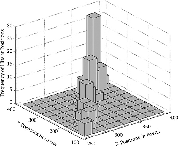
FIGURE 5.11
Pollutant coverage at different run length values.

FIGURE 5.12
Relation between kd and the number of robots at a = 30.
By combining the bacteria behavior with the flocking behavior, a swarm of robots is able to cover the environmental pollution As can be seen in Figure 5.13, the mean of the distribution of the flock of robots is close to the mean of the distribution of the pollutants. By changing the control parameters, it is possible to change the spread of the robots in the pollutants This feature is very useful in real-world applications
5.6 Summary
This chapter overviews our research work on the design and construction of autonomous robotic fish at Essex. Our research has been focused on two levels of complexity of fish locomotion by building a layered control architecture A number of robot behaviors have been developed to realize autonomous navigation and a number of fish swimming patterns were designed to realize the fish-like swimming motion as a carangiform fish does, including cruise straight, cruise in turning, sharp turn, and ascend-descend. Our robotic fish has a number of computers embedded in it (one Gumstix and three PIC microcontrollers) and over ten sensors. It can cope with unexpected obstacles and can swim in a three-dimensional unstructured environment as a real fish does.
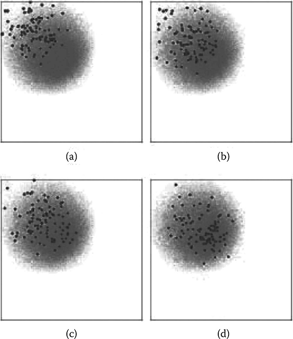
FIGURE 5.13
Sequence of the flock distribution in pollutants.
Currently we are working on the construction of SHOAL robotic fish for pollution monitoring at port. The field testing will be carried out at Gijón in Spain in 2012, as shown in Figure 5.14. These robotic fish could be potentially useful in many other marine and military applications such as investigating deep-sea fish behaviors, demining, seabed exploration, oil pipe leakage detection, military reconnaissance, etc To reach this goal, we will develop an efficient strategy for a school of robotic fish to cooperate on a common mission task Our future research will be focused on how to make our robotic fish more robust and adaptive like a real fish. Different types of fish swimming behaviors will be added gradually. Also, our robotic fish should be able to find the charging station similar to the way in which real fish look for food.
Acknowledgments
This project was financially sponsored by the European Union FP7 program, ICT-231646, SHOAL. Thanks to the other members of the EU SHOAL consortium, namely, BMT (Coordinator), Tyndall, THALÈS-SAFARE, The University of Strathclyde, and The Port Authority of Gijón Our thanks also go to the current team members at Essex, Ian Dukes, George Francis, and Bowen Lv, as well as previous team members Jindong Liu and Robert Knight, for their excellent contributions to the project

FIGURE 5.14
Test site at the Port of Gijón, Spain.
References
Arkin, R. 1998. Behaviour Based Robotics. Cambridge, MA: MIT Press.
Balch, T. 2000. The case for randomized search. Paper read at the Workshop on Sensors and Motion, IEEE International Conference on Robotics and Automation, San Francisco, CA, April 24-28, 2000..
Berg, H. C. and Brown, D. A. 1972. Chemotaxis in Escherichia coli analysed by 3D tracking. Nature, 239.
Brown, D. A. and Berg, H. C. 1974. Temporal stimulation of chemotaxis in Escherichia coli. Proceedings of the National Academy of Sciences, USA, 71(4): 1388-1392.
Drucker, E.G. and Lauder, G.V. 2002. Experimental hydrodynamics of fish locomotion: Functional insights from wake visualization. Journal of Integrative and Comparative Biology, 42: 243-257.
Gabriely, Y. and Rimon, E. 2001. Spanning-tree based coverage of continuous areas by a mobile robot. Annals of Mathematics and Artificial Intelligence, 31: 77-98.
Guo, S., Fukuda, T., Kato, N., and Oguro, K. 1998. Development of underwater micro-robot using ICPF actuator Paper read at the IEEE Conference on Robotics and Automation, Leuven, Belgium, May 16-20, 1998.
Hu, H., Liu, J., Dukes, I., and Francis, G. 2006. Design of 3D swim patterns for autonomous robotic fish. Paper read at the IEEE/RSJ International Conference on Intelligent Robots & Systems, Beijing, China, October 9-15, 2006.
Jalbert, J., Kashin, S., and Ayers, J. 1995. A biologically-based undulatory lamprey-like AUV. Paper read at the Autonomous Vehicles in Mine Countermeasures Symposium. Naval Postgraduate School, Monterey, CA.
Kato, N. 2000. Control performance in the horizontal plane of a fish robot with mechanical pectoral fins. IEEE Journal of Oceanic Engineering, 25(1): 121-129.
Lighthill, M.J. 1960. Note on the swimming of slender fish. Journal of Fluid Mechanics, 9: 305-317.
Liu, J. and Hu, H. 2004. A 3D simulator for autonomous robotic fishes. International Journal of Automation and Computing, 1(1): 42-50.
Liu, J. and Hu, H. 2010. Biological inspiration: From carangiform fish to multi-joint robotic fish. Journal of Bionic Engineering, 7(2): 35-48.
Liu, J., Hu, H., and Gu, D. 2006. A layered control architecture for robotic fish. Paper read at the IEEE/RSJ International Conference on Intelligent Robots and Systems, 9-15 October, Beijing, China.
Nikolaus, C and Alcherio, M 2007 Robust distributed coverage using a swarm of miniature robots. Paper read at the IEEE/RSJ International Conference on Robotics and Automation, San Diego, CA, October 29-November 2, 2007
Sfakiotakis, M., Lane, D. M., and Davies, J. B. C. 1999. Review of fish swimming modes for aquatic locomotion. IEEE Journal of Ocean Engineering, 24(2): 237-252.
Streitlien, K., Triantafyllou, G. S., and Triantafyllou, M.S. 1996. Efficient foil propulsion through vortex control. AIAA Journal, 34(11): 2315-2319.
Yamamoto, I. and Terada, Y. 2003. Robotic fish and its technology. Paper read at the SICE Annual Conference in Fukui, Fukui University, Japan.
Zheng, X., Jain, X., Koenig, S., and Kempe, D. 2005. Multi-robot forest coverage. Paper read at the IEEE International Conference on Robotics and Automation, Barcelona, Spain, April 18-22, 2005.