
10
Measurement of Brain Activity Using Optical and Electrical Methods
Atsushi Saito, Alexsandr Ianov, and Yoshiyuki Sankai
University of Tsukuba Tsukuba, Japan
CONTENTS
10.2 Methods to Measure Brain Activities
10.2.1 Brain Wave Bioelectric Signal Measurement
10.2.2 Measurement of Blood Information of the Brain
10.3.2 Signal Processing and Control Board
10.4.1 Operation Verification of the Hybrid Sensor Probe
10.4.2 Optical Data Collection Experiment
10.4.3 Assistive Device Control Experiment
10.5.1 Verification of Operation of the Hybrid Sensor Probe
10.5.2 Optical Data Collection Experiment
Abstract
There are patients who cannot produce bioelectric signals such as patients with advanced stages of amyotrophic lateral sclerosis or those who have suffered severe spinal cord injury These patients are unable to use bioelectrical signal-based assistive devices such as the robot suit HAL This chapter proposes a noninvasive brain activity scanning method for collecting the patient's movement intentions by developing a hybrid sensor that can measure both optical and bioelectrical signals of the same spot simultaneously and evaluate it The developed sensor consists of holography laser modules and electrodes The holography laser modules contain an emitter and receiver In order to evaluate the hybrid sensor, three kinds of experiments were carried out: (1) operation verification of the hybrid sensor probe in which the pulse waves and the alpha wave were measured with the hybrid sensor probe; (2) an optical data collection experiment in which the optical output was found to be high when the participant was in relaxation state; on the other hand, while the participant was executing mental tasks such as algebraic calculations the optical output lowered; and (3) an assistive device control experiment in which the participant tried to move the upper limb assis-tive device 10 times The upper limb movement was recorded 24 times during this period However, 7 times (out of 24) upper limb movement corresponded to the participant's intention was recorded 5 s before or after the switch was pressed We developed and evaluated a hybrid sensor that can collect both kinds of optical and bioelectrical signals from the same spot on the scalp in order to measure brain activity by using optical and bioelectrical data.
10.1 Introduction
It is difficult for patients suffering from advanced stages of amyotrophic lateral sclerosis (ALS) and severe spinal cord injuries to transmit bioelectri-cal signals from the brain to peripheral nerves They cannot use assistive devices such as the robot suit HAL that are controlled using bioelectric signals (Hayashi et al 2005; Kawamoto and Sankai 2005; Lee and Sankai 2003; Nakai et al. 2001; Okamura, Tanaka, and Sankai 1999; Suzuki et al. 2007) measured at the peripheral nerves Residual functions such as voice or eye movements can be used with assistive devices, but these methods place great strain on patients. A brain-computer interface (BCI) that collects the patient's movement intentions and controls devices makes it easier for patients to use assistive devices in this manner
In order to realize a user-friendly BCI, it is necessary to measure brain activity noninvasively There are several methods for scanning brain activities Functional magnetic resonance imaging (fMRI), positron emission tomography (PET), and magnetoencephalography (MEG) are methods that measure brain activity accurately However, these methods require very large and expensive equipment Their readings also contain a delay, due to the fact that they are based solely on blood flow. It is not possible to maintain a comfortable lifestyle and use these devices for long periods of time
On the other hand, there are methods using portable devices, such as electroencephalograms (EEGs) and functional near-infrared spectroscopy (fNIRS) EEG is a method that measures brain activity using electrical brain waves that propagate through the scalp (Sanei and Chambers 2007) Brain waves can be measured using a small, portable device, so an EEG is suitable for daily use EEG signals are, however, susceptible to noise Bioelectrical signals originating from eye movements, facial muscular movement, and external power sources such as electronic devices are common noise sources Furthermore, due to the fact that the electrical signals produced by the brain have to travel through the skull and cerebrospinal fluid, it is difficult to determine the origin of the signal
fNIRS is a method that measures brain blood circulation information by using near-infrared spectroscopy (NIRS). Differences in blood flow volume reflect neural activities because higher neural activities require higher oxygen concentration and, therefore, higher blood circulation By using noninva-sive optical probes, it is possible to measure cortical neural activities around a brain (Koizumi et al 2003; Koizumi et al 2005) Combining bioelectrical activity data collected by brain electrodes with blood circulation data collected by optical probes, it is possible to measure brain activity and infer the area of the brain that is active with a higher degree of precision than with the methods currently available
The objective of this chapter is to develop a hybrid sensor probe that can measure both optical and bioelectrical signals from the same spot simultaneously
10.2 Methods to Measure Brain Activities
This section explains the methods used to measure brain activities
10.2.1 Brain Wave Bioelectric Signal Measurement
EEG is the process of measuring electrical potential generated by several firing neurons simultaneously These electrical signals propagate through the brain, skull, cerebrospinal fluid, and scalp. A common method for measuring brain waves is measuring voltage by placing noninvasive low-impedance electrodes on the patient's scalp Some common passive brain waves include the following:
• Delta: 3 Hz and lower (deep sleep, when awake pathological)
• Theta: 3. 5-7.5 Hz (creativity, falling asleep)
• Alpha: 8-13 Hz (relaxation, closed eyes)
• Beta: 14-30 Hz and higher (concentration, logical and analytical thinking)
• Gamma: greater than 30 Hz (simultaneous processes)
It is important to note that voltages drop with the fourth power of the radius, so neural activities from deep sources are more difficult to register than activities from neurons near the skull (Johnson and Guy 1972).
In addition, the bioelectrical signals in the head reflect activation of the head musculature, eye movements, interference from nearby electric devices, and changing conductivity in the electrodes due to the subject's movements or physicochemical reactions at the electrode sites. All of these activities that are not directly related to the current cognitive processing of the subject are considered noise
Bioelectrical signals were analyzed by using common signal processing techniques.
10.2.2 Measurement of Blood Information of the Brain
In order to measure blood information of the brain using optical data, Lambert-Beer's law was used.
According to Lambert-Beer's law, there is a logarithm relationship between the incident light beams Iin and the transmitted light beam Iout, absorption coefficient e, the distance the light travels d, and concentration of the solution C.
(10.1)
The light absorbance Abs for liquids is defined as:
(10.2)
Lambert-Beer's law, however, usually does not apply for very high concentrations or if the material is highly scattering. When light is applied to blood it is attenuated by both absorption and scattering phenomena. Furthermore, when light is used on the head, the light emitter and receiver are not facing each other. Therefore, a modified version of Lambert-Beer's law is necessary. The modified Lambert-Beer's law is as follows:
(10.3)
<d> is the average length of the path followed by the light and S is a component affected by scattering
When a light beam is applied to a living organism, its intensity also varies according to the organic tissues under the target region and blood flow.
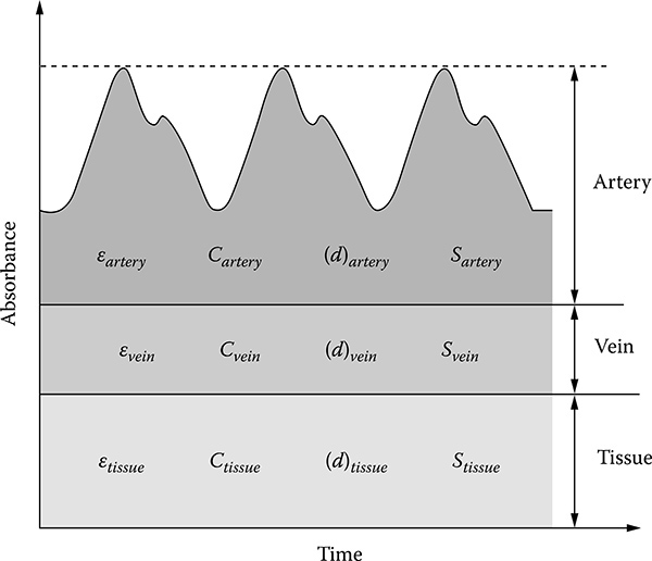
FIGURE 10.1
Variation of light absorbance with time. The components affecting light passing through a living body are classified into three components: organic tissues, veins, and arteries.
The components affecting light passing through a living body are classified into three components: organic tissues, veins, and arteries, as shown in Figure 10.1. In this case, absorbance is expressed as formula (10.4):
(10.4)
etissue, evessel, and eartery are the absorption coefficients of tissues, vessels, and arteries. Ctissue, Cvessel, and Cartery are the concentration variations of tissues, vessels, and arteries. <dtissue,>, <dvessel,>, and <dartery,> are the average lengths of the light paths in tissues, vessels, and arteries. Stissue, Svessel, and Sartery are the scatter of tissues, veins, and arteries
If we consider the intensity and wavelength of the incisive light constant and if we also consider that the variation caused by scattering can be ignored, we can evaluate the impact of each component in formulas (10.4)
Organic tissues are static elements; therefore, the concentration, light path, and absorption rate are constant
Venous blood flow has a constant flow rate. Therefore, the shape of the veins is constant and the light path does not change. But because blood under a beam of light is always changing and because the blood does not have a uniform concentration, the fluid concentration and absorption rate are not constant
Arterial blood flow is periodical. Therefore, there are changes in pressure, which are responsible for changes in the shape of the arteries This variation of shape changes the light path. Similar to venous blood, the presence of blood flow means that the concentration and absorption rate are variable.
If Stissue, Svein, and Sartery are constant, variation of absorbance is expressed as formula (10.5):
(10.5)
AAbs is variation of absorbance. <Adartery> is variation of the average length of the path followed by the light in the artery. K is the constant including the effect of tissues, veins, and scattering
Therefore, it is safe to assume that variation of light detected by the light receiver is a direct result of the variation in blood flow and concentration.
10.3 Device Development
10.3.1 Hybrid Sensor Probe
The objective is to develop a sensor that can capture both optical and bioelec-trical data simultaneously by using a single sensor probe A hybrid sensor probe consists of the following components
• Optical elements
• Electrode
• Amplifier
Optical elements include a light emitter, a light receiver, and a light-guiding transparent acrylic bar. Holography laser modules were used as light sources for the optical sensors The laser module has a laser diode and photodiodes and is able to keep the size of the sensor small. Common near-infrared imaging devices usually collect the light using optical fibers and the optical signals are converted into electric signals on the external control board The hybrid sensor probe converts optical signals into electrical signals. Therefore, an optical fiber is not necessary, and handling of the hybrid sensor probe is easy The light is emitted to the scalp through the light-guiding bar The light-guiding bar is also used to push hair aside
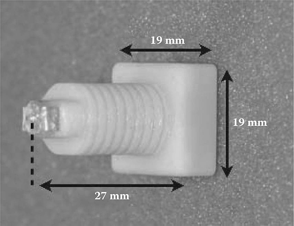
FIGURE 10.2
The hybrid sensor probe developed. Dimensions: 19 mm x 19 mm x 27 mm; weight 4. 5 g.
The material chosen for the electrode was silver chloride. Silver chloride was chosen because of its low price and good performance. It has very low impedance and can be acquired for relatively low prices. A buffer circuit was added to the electrode because the electrical current drained from the scalp by the electrode may not be enough to overcome the relative high impedance from the cable The electrode was located in the end of the hybrid sensor probe. The light-guiding bar was located in the center of the electrode.
An amplifier converted small current signals from the photodiodes output into voltage signals. It also worked to buffer the signals measured on the electrode to decrease output impedance
Figure 10.2 shows the hybrid sensor probe developed. Its dimensions were 19 mm x 19 mm x 27 mm and its weight was 4. 5 g. It was attached directly to a standard EEG cap.
10.3.2 Signal Processing and Control Board
In order to process signals measured by the hybrid sensor probes, a signal processing and control board was developed The board consisted of signal processing circuits, laser driver circuits, and a microcontroller
Analog signal processing circuits amplified and filtered the signals measured at the hybrid sensor probes It was able to change the gain and cutoff frequency using the microcontroller
Laser drive circuits stabilized the power of the laser diode and controlled the light emission The timing of the light emission was controlled by the microcontroller
The microcontroller worked to control the signal processing circuits and the laser drive circuits, to convert analog signals into digital signals, and to communicate with the other devices. The board had a USB port and some digital I/O ports to allow communication with an external device such as a computer or actuators. The microcontroller chosen was powerful enough to execute simple calculations and basic digital processing techniques. More advanced software technologies such as neural networks and genetic algorithms require an external PC. The controller analog sampling rate was set to 1 kHz and A/D conversion resolution was set to 12 bit.
10.4 Experiment
In order to evaluate the hybrid sensor, three experiments were carried out. The first one was to verify the operation of the hybrid sensor probes. The sec-ond experiment was to collect optical data using the hybrid sensor probes The third was to control the assistive device using the hybrid sensor probes
10.4.1 Operation Verification of the Hybrid Sensor Probe
The purpose of this experiment was to verify the operation of the hybrid sensor probes In this experiment, two hybrid sensor probes and a reference electrode were used. One sensor acted as an emitter and the other acted as a receiver. The optical sensor emitted a laser wavelength of 805 nm. This wavelength has high permeability on human skin. Furthermore, as shown in Figure 10.3, 805 nm is the isosbestic point of oxyhemoglobin and deoxyhe-moglobin. Hence, it suffers little influence from oxygen saturation.
In order to measure brain blood information, it is necessary to reach the light emitted by the probe to the cortex The distance from the scalp to the cortex is 15-20 mm. The depth to which light infiltrates depends on the distance between the emitter and the receiver. If a brain is active, the influence that light receives from a brain is greater than the influence from other tissues such as skull and skin Considering the effect of the distance between the emitter and the receiver, a distance greater than 20 mm is enough to measure brain blood information (Kato 2004). Therefore, the distance between the emitter and the receiver was set to 20 mm
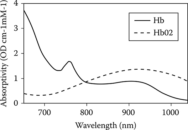
FIGURE 10.3
Hemoglobin absorptivity versus wavelength: 805 nm is the isosbestic point of oxyhemoglobin and deoxyhemoglobin. This wavelength has high permeability on human skin and is well absorbed by hemoglobin. © 2009 IEEE.

FIGURE 10.4
Position of the hybrid sensor probes and a reference electrode attached to the participant's forehead © 2009 IEEE.
The hybrid sensors and a reference electrode were connected to the signal processing and control board The board was connected to the PC through a USB port. The board communicated with the PC using a baud rate of 460800 via a serial communication method The signals measured by the hybrid sensors were saved on the PC
The probes and the electrode were placed on the participant's forehead, as shown in Figure 10.4. The participant was healthy 25-year-old male. The participant was seated in a relaxed sitting position First, to verify the optical part of the hybrid sensor probe, the returning pulse wave was measured on the forehead Second, to verify the electrode of the hybrid sensor probe, alpha waves were measured. When the subject's eyes were closed, the alpha waves increased The voltage between the reference electrode and the electrode on the hybrid sensor probe was measured We computed the short-time Fourier transform of the bioelectrical signals The size of the window was 4096 points.
10.4.2 Optical Data Collection Experiment
In this experiment two hybrid sensors were used One sensor acted as an emitter and the other acted as a receiver The optical sensor emitted a wave-length laser of 805 nm The setup was the same as in the last experiment.

FIGURE 10.5
Experimental system setup for assistive device control experiment. The hybrid sensors and a reference electrode were connected to the signal processing and control board. The board was connected to the PC through a USB port. The board communicated with the PC using a baud rate of 460800 via a serial communication method. The signals measured by the hybrid sensors were saved on the PC. The sensors were placed on the participant's forehead.
The participant was a healthy 23-year-old male. The participant was seated in a relaxed sitting position with his eyes closed. He was asked to perform mental calculations.
10.4.3 Assistive Device Control Experiment
The purpose of this experiment was to control the upper limb assistive device, a part of the robot suit HAL, by using brain activity signals measured by the hybrid sensors. Figure 10.5 shows the experimental system setup for the assistive device control experiment. In this experiment, two hybrid sensor probes and a reference electrode were also used The connection of the sensors, the board, and the PC were the same as in the last experiment The board was connected to the upper limb assistive device through the digital I/O ports. A push switch was also connected to the board through a digital I/O port.
During a task that requires mental concentration such as mental arithmetic, blood flow volume of the prefrontal cortex is increased (Tanida et al. 2004). In this experiment, we used this phenomenon as the switch to control the assistive device. If blood flow volume was increased, the optical output measured by the hybrid sensor probe was decreased Upon detection of a decrease in the optical output, the movement of the assistive device was changed into bend or extension A single binary signal created by the controller after analyzing the signals from the optical sensor turned the actuator inside the device on and off The control board was programmed to invert the state of the actuator The state of the actuator was controlled every 0 8 sec The control signal was inverted when the maximum of the signals measured by optical sensors during 0 8 s went below a threshold value The threshold value was chosen by observing the data collected during the relaxation and metal calculation phase of the optical data collection experiment A period of 0 8 s was chosen because that was the average heartbeat period of the participant Ideally, each time the participant focused on a mental task the assistive device would turn on or off
The participant and his task were the same as in the last experiment He was given a push switch to use to press to signify when he started the mind task The timing of the beginning of the mental calculations was determined by the participant
10.5 Result
10.5.1 Verification of Operation of the Hybrid Sensor Probe
Figure 10.6 shows the variation of the optical output. The intensity changed periodically Pulse waves rise up in the heart's contraction phase and fall in the diastole phase. The pulse wave has an inflection point in the diastole phase The signals measured in this experiment had the same characteristics of the pulse waves
Figure 10.7 shows a spectrogram of the EEG signals measured by the electrodes The frequency band of alpha waves is 8-13 Hz While the subject's eyes were closed, the signal intensity around 10 Hz was strong At 18 s, the subject's eyes opened and the signal intensity around 10 Hz became weak Therefore, alpha waves could be measured with the hybrid sensor probe
10.5.2 Optical Data Collection Experiment
As shown in Figure 10.8, the optical output was found to be high when the participant was in relaxed state On the other hand, while the participant was executing mental calculations such as algebra the optical output was lowered.

FIGURE 10.6
Optical data measured from the participant's forehead.

FIGURE 10.7
Spectrogram calculated from EEG signals measured by the electrodes.
10.5.3 Assistive Device Control Experiment
The participant tried to control the upper limb assistive device ten times, shown in Figure 10.9. Upper limb movement was recorded twenty-four times during this period; however, seven times (out of twenty-four), upper limb movement corresponding to the participant's intention was recorded 5 s before or after the switch was pressed
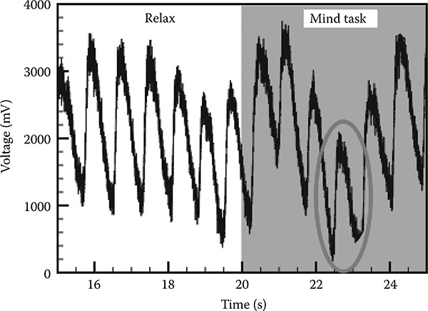
FIGURE 10.8
Results corresponding to data collection experiment. Data included brain blood circulation information measured using optical module of the hybrid sensor. The circle shows that the optical density was lowered when the participant switched from relaxed mode to mental task mode. © 2009 IEEE.
10.6 Discussion
In Figure 10.9 the uppermost graph shows data for the first 100 s, during which the participants tried to move the upper limb assistive device four times. However, the assistive device moved fifteen times, and the movement corresponded to the participant's intention twice by moving within 5 s before or after the button was pressed. Between 100 and 195 s the participant tried to move the upper limb assistive device six times, and the device moved nine times, during which the movement corresponded to the participant's intention five times by moving within 5 s before or after the button was pressed.
During the first few tries the chance of success was found to be low. But, after several trials, the probability of success increased considerably
The reason for the low success rate in the initial stage of the experiment can be attributed to a lack of learning history. However, the human brain can adapt itself to unfamiliar conditions through repeated learning and can operate precisely There were cases when the assistive device moved before the participant pressed the button This may be attributed to the fact that because the participant was free to decide when to start the mental calculations, his brain was already prepared to start calculating.
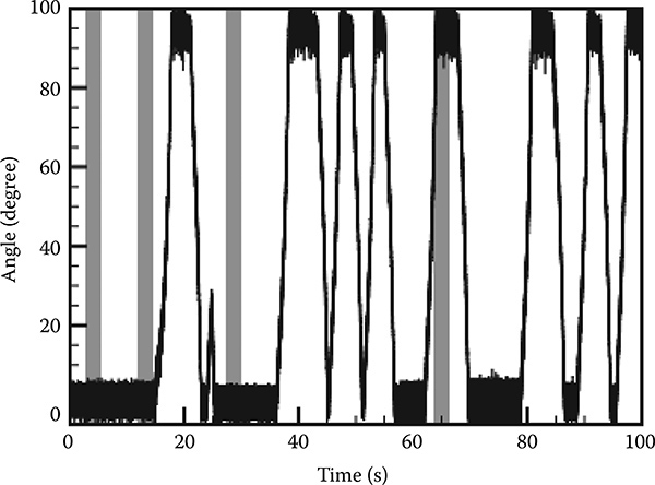
FIGURE 10.9
Graphs showing results of assistive device control experiments. Gray area represents the period of mind task performance, and the black line is the angle of the upper limb assistive device. The uppermost graph shows data from 0 to 100 s. The graph below shows the data cor-responding to 100 to 195 s. © 2009 IEEE.
The user set the threshold value based on observations during the optical data collection experiment. There was no learning process executed by the controller. The optical data collection experiment and assistive device control experiment were executed at different times. The human body's biochemical state is dynamic; therefore, the threshold value varies according to different periods of the day. Implementing a dynamic threshold value by using learning algorithms can potentially increase the success rate of the experiment. It is important to notice that bioelectrical signals from the brain were not used. The use of bioelectrical signals could increase the accuracy of the test
10.7 Conclusion
In this chapter, a hybrid sensor that can collect both bioelectrical and optical data from the same spot on the scalp was developed and evaluated in order to measure brain activity. Data analysis during and after the experiments showed that the bioelectrical data collected by the hybrid sensor were very similar to the data collected by an ordinary disposable electrode Similarly, the optical data collected by the hybrid sensor were similar to the data collected using a standard functioning near-infrared imaging device Our next step is to use this new technology to accurately register the user's movement intentions and use these data to accurately control assistive devices
References
Hayashi, T., Kawamoto, H and Sankai, Y. 2005. Control method of RobotSuit HAL working as operator's muscle using biological and dynamical information. IEEE/ RSJ International Conference on Intelligent Robots and Systems, Edmonton, Canada, August 2-6, 2005.
Johnson, C. and Guy, A. 1972. Nonionizing electromagnetic wave effect in biological matherials and systems. Proceedings of the IEEE, 60(6): 692-718.
Kato, T. 2004. Principle and technique of NIRS-Imaging for human brain FORCE: Fast-oxygen response in capillary event. International Congress Series, 1270: 85-90
Kawamoto, H and Sankai, Y 2005 Power assist method based on PhaseSequence and muscle force condition for HAL. Advanced Robotics, 19(7): 717-734.
Koizumi, H., Maki, A., Yamamoto, T., Sato, H., Yamamoto, Y. and Kawaguchi, H.. 2005. Non-invasive brain-function imaging by optical topography. Trends in Analytical Chemistry, 24(2): 147-156.
Koizumi, H., Yamamoto, T., Maki, A., Yamashita, Y., Sato, H., Kawaguchi, H and Ichikawa, N 2003 Optical topography: practical problems and new applications. Applied Optics, 42(16): 3054-3062.
Lee, S and Sankai, Y 2003 The natural frequency-based power assist control for lower body with HAL-3 International Conference on Systems, Man and Cybernetics, Washington, DC, October 5-8, 2003.
Nakai, T Lee, S., Kawamoto, H and Sanaki, Y 2001 Development of powered assis-tive leg for walking aid using EMG and Linux Asian Symposium on Industrial Automation and Robotics, Bangkok, May 17-18, 2001.
Okamura, J., Tanaka, H., and Sankai, Y 1999 EMG-based prototype powered assis-tive system for walking aid Asian Symposium on Industrial Automation and Robotics, Bangkok May 6-7, 1999
Sanei, S. and Chambers, J. A. 2007. EEG Signal Processing. New York: Wiley-Interscience.
Suzuki, K., Mito, G., Kawamoto, H., Hasegawa, Y and Sankai, Y 2007 Intention-based walking support for paraplegia patients with RobotSuit HAL Advanced Robotics, 21(12): 1441-1469
Tanida, M., Sakatanib, K., Takanoc, R and Tagaic, K 2004 Relation between asymmetry of prefrontal cortex activities and the autonomic nervous system during a mental arithmetic task: near infrared spectroscopy study. Neuroscience Letters, 369: 69-74.