
9
Nanorobotic Manipulation for a Single Biological Cell
Toshio Fukuda and Masahiro Nakajima
Nagoya University Nagoya, Japan
Mohd Ridzuan Ahmad
Universiti Teknologi Malaysi Skudai Johor, Malaysia
CONTENTS
9.1 Background of Nanorobotic Manipulations
9.2 Single-Cell Analysis and Nanosurgery System
9.3 Principles of Stiffness Measurements for a Single Cell
9.3.1 Stiffness Measurement of a Single Cell Based on Nanoindentation Technique
9.3.2 Stiffness Measurement Using Different Indenter Tip Shapes
9.3.3 Stiffness Measurement Using Nanoprobes
9.3.3.1 Measurement of Single-Cell Stiffness Using a Soft Nanoprobe
9.3.3.2 Measurement of Single-Cell Stiffness Using Hard Nanoprobes
9.4 Nanorobotic Manipulations inside Various Kinds of Microscopes
9.4.1 Nanorobotic Manipulation System inside Electron Microscopes
9.4.2 Observations of Biological Samples by E-SEM
9.5 Stiffness Measurements of Single Cells Using Conventional AFM Cantilevers
9.5.1 Stiffness Measurement of Single Yeast Cells Depends on Cell Sizes
9.5.2 Stiffness Measurement of Single Yeast Cells Depends on Growth Phases
9.6 Stiffness Measurements of Single Cells Using Nanoprobes
9.6.1 Fabrication of Nanoprobes
9.6.2 Calibration of Soft Nanoprobes
9.6.3 Stiffness Measurement of Single Yeast Cells by Nanoprobes
Abstract
Nanorobotic nanomanipulation inside electron microscopes is presented in this chapter We constructed an environmental scanning electron microscope (E-SEM) nanomanipulation system to observe and manipulate biological samples in nanoscale resolution with water-containing condition The system can be used for various applications in the direct observation and manipulation of biological samples with nondrying, nondyeing, noncoating treatments, with a 7-degrees of freedom nano-manipulator with a sharp pyramidal end-effector and a cooling stage; that is, a temperature controller We demonstrated in situ measurements of mechanical properties of individual W303 wild-type yeast cells using several types of nanoprobes Compression experiments to penetrate the cell walls of single cells of different cell sizes (about 3-6 um diameter) and growth phases (early log, mid-log, late log, and saturation) were conducted The advantage of the integrated E-SEM nanomanipulation system relies on its capability to perform in situ local direct observation and manipulation of biological samples and its ability to control environmental conditions
9.1 Background of Nanorobotic Manipulations
The possibility of controlling the structure of matter atom by atom, which is now called nanotechnology, was first discussed seriously by Richard Feynman in 1959 (Feynman 1960) Nanotechnology has an important role in combinations of the top-down and bottom-up approaches to construct highly-integrated devices as shown in Figure 9.1. Wide-scale controlled devices from the atomic scale to meter scale will be realized in the near future
Presently, nanomanipulation can be applied to the scientific exploration of mesoscopic phenomena and the construction of prototype nanodevices It is a fundamental technology for property characterization of nanomaterials, nanostructures, and nanomechanisms; for the fabrication of nanoscale building blocks; and for the assembly of nanodevices Nanoelectromechanical systems (NEMS) are expected to realize highly integrated, miniaturized, and multifunctional devices for various applications (Craighead 2000) To realize such a high precision system, direct usage of bottom-up fabricated nanostructures is effective.
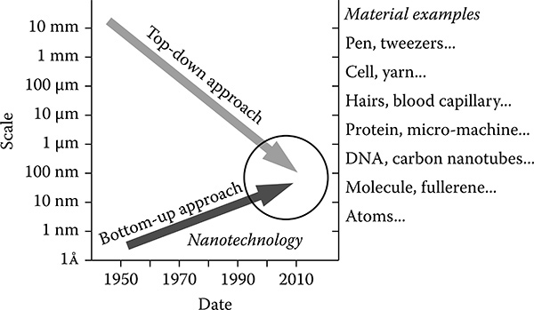
FIGURE 9.1
Schematic diagram of nanotechnology approaches (top-down and bottom-up).
Recently, the evaluation of bio-samples has received much attention for nano-bio applications in nanobiotechnology (Leary, Liu, and Apuzzo 2006; Staples et al 2006) Single-cell analysis has received a lot of attention for its potential to reveal unknown biological aspects of individual cells Nanomanipulation techniques are a promising way to develop nano-bio applications on the single-cell level for drug delivery, nanotherapy, nanosurgery, and so on.
9.2 Single-Cell Analysis and Nanosurgery System
Microbiology has traditionally been concerned with and focused on studies at the population level (105-107 cells; Sedgwick et al. 2008). On the other hand, single-cell analysis contributes to important research on the existence of cellular heterogeneity within individual cells This technique is important for next-generation analysis methods in biological and medical fields.
Cellular heterogeneity is widespread in bacteria and increasingly apparent in eukaryotic cells (Ferrell and Machleder 1998) Heterogeneity at the single-cell level is typically masked and is therefore unlikely to be acknowledged in conventional studies of microbial populations, which rely on data averaged across thousands or millions of cells Bulk-scale measurements made on a heterogeneous population of cells provide only average values for the population and are not capable of determining the contributions of individual cells.
The types of individual differences contributing to heterogeneity within a microbial population can be divided into at least four general classes: genetic differences, biochemical differences, physiological differences, and behavioral differences (Avery 2006).
The sizes of biological cells are distributed mainly around the 100 to 1 }im range. Their components, proteins, DNA, etc., are micrometer to nanometer sizes (Wilson and Hunt 2002). Hence, the micronanomecha-tronics and micronanorobotics contribute to investigating and imitating single-cell properties
We proposed a single-cell nanosurgery system to realize single-cell diagnosis, extraction, cutting, injection, and embedded micronanode-vices. A conceptual schematic is shown in Figure 9.2. Our approaches are based on nanomanipulation technologies using nanotools As described in the following sections, we developed an environmental SEM (E-SEM) nanorobotic manipulation system to manipulate and control local environments for biological samples at the nanoscale With this system we have realized the direct observation and manipulation of water-containing biological samples under nanometer high-resolution imaging. Based on the proposed system, the novel local stiffness evaluation, local electrical characterization, local cutting, local injection, and local extraction of biological organisms are presented by micronanoprobes based on the E-SEM nanorobotic manipulation system for a future single-cell diagnosis and surgery system
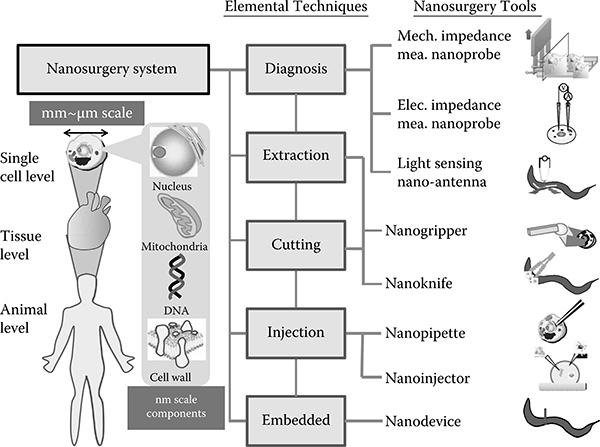
FIGURE 9.2
Schematic of the nanoindentation process.
9.3 Principles of Stiffness Measurements for a Single Cell
9.3.1 Stiffness Measurement of a Single Cell Based on Nanoindentation Technique
A schematic of a nanoindentation process for a single cell is shown in Figure 9.3. An atomic force microscope (AFM) cantilever with a stan-dard or modified tip is mounted on the nanomanipulator stage. The nanomanipulator is used to approach, contact, and indent the cantilever's tip on a single biological cell. Force is calculated from two parameters, that is, the cantilever's deflection angle, 8, and the cantilever's length, L, which can be obtained from the SEM images.

FIGURE 9.3
Schematic of nanoindentation process.

FIGURE 9.4
Schematic of beam deflection.
Figure 9.4 shows a schematic of the beam deflection. By using Macaulay's method (Stephen 2007), which is also known as the double integration method, the deflection of the beam can be represented in two relationships; that is, the length deflection, 5, and the angular deflection, 9.
Macaulay's method consists of three steps; that is, derivation of the bending moment, M(x), which acts internally at every point in the interval between x = 0 and x = L; integration of M(x) to obtain the beam slope; and second integration to get the elastic curve, v(x) . In integrating M(x), integration of two constants will emerge; that is, C1 and C2. In order to evaluate these constants, appropriate boundary conditions of the beam will be used to determine their values Finally, the value of x = L is substituted into each equation to find the deflection and slope at the tip of the cantilever.
Equilibrium equation for the sum of moments around point h,
(9.1)
Solving the moment equation for M gives
(9.2)
The moment-curvature relationship can be expressed as
(9.3)
Therefore, the general equations for the slope and deflection of the cantilever are
(angular deflection in radians) (9.4)
(length deflection) (9.5)
The negative sign indicates the direction of the force. Now, we have the standard equations for the beam deflection under a condition as shown in Figure 9.4. Back to our discussion regarding the visual-based approach for force measurement of the AFM cantilever, the deflection of the AFM cantilever has to be expressed in angular deflection and not in length deflection.
By using basic mathematical manipulation from Equations (9.4) and (9.5), we arrive at the final equation of the cantilever deflection with respect to the angular deflection,
(9.6)
where 5, 9, and L are the cantilever deflection, the angular deflection in radians, and the total length of the cantilever. The values of 9 and L are determined from analysis of the SEM images. Finally, by using Equation (9.6), modification of the Hooke's law can be written as
(9.7)
Evaluation of Equation (9.7) was conducted experimentally by comparing the result of 5 obtained from a direct displacement measurement
In our experiment, we obtain 5 from the SEM image obtained from Equation (9.6). Because the base of the AFM cantilever was in fixed condition, the value of 5 can be obtained directly from the length displacement of the cantilever's tip Therefore, both parameters, 5 and 9, can be determined from the high-magnification SEM image.
9.3.2 Stiffness Measurement Using Different Indenter Tip Shapes
Figure 9.5 shows a schematic of the indenter tip-sample contact for three different indenter tips; that is, cylindrical, conical, and spherical The parameters I, h, r, 8, and R are indentation depth, sample height, radius of the cylindrical tip, and radii of the spherical tip for conical and spherical, respectively
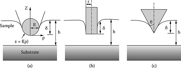
FIGURE 9.5
Schematics of the tip-sample contact for (a) spherical, (b) cylindrical, and (c) conical tips.
The Hertz model is used for the indentation based on a spherical tip and the Sneddon model is used for the indentation based on the cylindrical and conical tips Therefore, the selection of the Hertz or Sneddon model depends on the shape of the indenter tip
In 1882, Hertz published a classic paper that aroused considerable interest (Hertz 1882). The load-displacement relation based on a spherical tip from Hertzian analysis is
(9.8)
where v is the Poisson's ratio of the sample.
In 1965, Sneddon published a paper on indentation of linear half spaces by rigid punches of arbitrary profile (Sneddon 1965). Although he showed the load-displacement relationship of several tip shapes, only the cylindrical and conical shapes are applied in our case The load-displacement relations based on cylindrical and conical tips are
(9.9)
(9.10)
The indenter is described by an arbitrary function, z = f(p) that is rotated about the z axis to produce a solid of revolution. Nevertheless, Pharr, Oliver, and Brotzen (2002) have shown that Equations (9.8)-(9.10) are also valid for a nonrevolute indenter as well such as pyramidal tip.
9.3.3 Stiffness Measurement Using Nanoprobes
We designed two approaches for determining the stiffness of a single cell as shown in Figure 9.6.
The first approach is based on the buckling phenomenon of a nanoprobe. A schematic of this approach is shown in Figure 9.6a. It is, to the best of our knowledge, a novel technique in determining the stiffness of a cell (Ahmed et al, 2008a) In this technique, the nanoprobe and the cell can be modeled as two springs in series. In order to model the nanoprobe as a spring, firstly, the nanoprobe should be able to buckle linearly, and secondly, it should have a lower or equivalent spring constant as the cell This technique prevents damage to the cell because the indentation is minimized from the buckling effect of the so-called soft nanoprobe, which avoids excessive indentation being applied to the cell.

FIGURE 9.6
Schematic diagrams of nanoprobe indentation experiments indicate local single-cell stiffness measurement using (a) a soft nanoprobe and (b) a hard nanoprobe.
The second approach for the measurement of cell stiffness is based on a hard nanoprobe, which relies on deformation of the cell in order to measure its stiffness. A schematic of this approach is shown in Figure 9.6b. By knowing the applied compression force and the deformation of the cell, the stiffness of the cell can be measured In order to fabricate a hard nanoprobe, strong material that is hard to bend is needed We used tungsten to construct a hard nanoprobe To prevent excessive indentation force on the cell by the hard nanoprobe, this process has to be performed by avoiding any sudden pressure that can interrupt the chemical activities of the cell; for example, a mechanotransduction effect The other preventive step is to use a lower cantilever spring constant.
The hard nanoprobe can also be used for single-cell surgery In theory, all hard nanoprobes must be able to penetrate the cell; however, in practice, for yeast cells, only some nanoprobes can penetrate the cells, whereas others are only limited to cell stiffness measurement only This is because to penetrate the cell, more compression force is needed This excessive force may exceed the force limits of the nanoprobe, causing failure.
9.3.3.1 Measurement of Single-Cell Stiffness Using a Soft Nanoprobe
The spring constant of the cell, kcell can be calculated from the relationship of two springs in series as described in Equation (9.11).
(9.11)
where kneedle is the spring constant of the soft nanoprobe, Atotal is the total displacement of the nanoprobe and the cell, and Acell is the deformation of the cell
The Hertz and Sneddon models, which are based on the shape of the tips, that is, conical, spherical, and cylindrical, were used to estimate the Young's modulus of the cells The equations are derived from the classic Hertz mechanics model for linear elastic material (Pharr, Oliver, and Brotzen 2002). Parameters E, v, a, R, a, and 8 are the Young's modulus; the Poisson's ratio (v = 0. 5 for soft biological materials; Lanero et al. 2006) of the elastic half space (cell's surface); the half opening angle of a conical tip; the radius of curvature of a spherical tip; the radius of a cylindrical tip; and the displacement of the cantilever, respectively. Values for a, R, and a were obtained from E-SEM images, and determination of the value of 8 is obtained from Equation (9.6), respectively.
The following Equations (9.12)-(9.14) are used to estimate the stiffness of the cell from an indentation by an indenter, which has a body of revolution Si-Ti and W2 nanoprobes are not a true body of revolution because the needles have a rectangular cross section. However, it has been shown that the error using models for a non-body of revolution is very small as explained in detail by Dao et al. (2001) and King (1987).
(9.12)
(9.13)
(9.14)
The models predict that the load depends on the indentation according to a power law related to the tip geometry (Lanero et al. 2006). In order to choose the correct tip geometry, an equation of the form F = aP was fitted to force versus indentation curves using commercial fitting software, where the exponent b depends on the tip shape.
For buckling nanoprobe experiments, we obtained a value of b close to 2, characteristic of a conical tip Interestingly, for a hard nanoprobe, a value close to 1 was obtained for b, from which the experimental data were then fitted using a cylindrical model. To calculate the applied force, Fconfe in Equation (9.11), Hooke's law based on a cell spring constant, that is, F = fccerAell, was used.
The final equation of the Young's modulus of the cell obtained using a soft nanoprobe is expressed in Equation (9.15).
(9.15)
9.3.3.2 Measurement of Single-Cell Stiffness Using Hard Nanoprobes
The estimation of the Young's modulus of a single cell by hard nanoprobes was also based on the Hertz-Sneddon continuum mechanics model.
The applied force, F lindrical, in Equation (9.14), was calculated using the following equation:
(9.16)
where k, 9, and L are the spring constant, the displacement angle in radians, and the length of the cantilever, respectively It should be noted here, however, that the spring constant obtained from the manufacturer's specifications might not be accurate. Possible calibration methods can be performed to determine the exact spring constant of the cantilever prior to the application of the cantilever on the cell stiffness measurement such as a parallel beam approximation approach (Sader 1995), a scanning vibrometry method (Mendels et al. 2006), or a reference piezolever approach (Aksu and Turner 2007). Equation (9.10) was derived from Hooke's law; that is, F = kô, where ô is the displacement of the cantilever, which was obtained by using ô = 9(2/3)L.
The final equation of the Young's modulus of the cell obtained using a hard nanoprobe is expressed in Equation (9.17):
(9.17)
9.4 Nanorobotic Manipulations inside Various Kinds of Microscopes
Nanomanipulation has received much attention because it is an effective strategy for property characterization of individual nanoscale materials and the construction of nanoscale devices (Du, Cui, and Zhu 2006). A manipulation system and an observation system, in other words, a microscope, are necessary for nanomanipulations.
Figure 9.7 shows the strategies of two-dimensional and three-dimensional nanomanipulations under various kinds of microscopes An optical microscope (OM) is one of the most common and basic microscopes. However, its resolution is limited to ~100 nm because of the diffraction limit of the optical wavelength (~400 to ~800 nm; Lewis et al. 2003). Hence, special techniques (using, for example, evanescent light or fluorescent light) are needed for the observation of nanometer scale objects (Hell 2007). To observe nanoscale objects, a resolution higher than nanoscale is required. Scanning probe microscopes (SPMs) and electron microscopes (EMs) are readily used for nanoma-nipulation techniques.
9.4.1 Nanorobotic Manipulation System inside Electron Microscopes
The sample chambers of conventional SEMs and transmission electron microscopes (TEMs) are set under a high vacuum (HV) to reduce the distur-bance of the electron beam for observation (Fukuda, Arai, and Dong 2003).

FIGURE 9.7
Elemental technologies of a nanosurgery system.
To observe water-containing samples—for example, bio-cells—appropriate drying and dyeing treatments are needed before observations. Hence, direct observations of water-containing samples are normally quite difficult using these electron microscopes. We have presented the assembly of carbon nanotubes (CNTs) based on a nanorobotic manipulation system inside an SEM and TEM, called a hybrid nanorobotic manipulation system (Nakajima, Arai, and Fukuda 2006). An overview of the constructed hybrid nanorobotic manipulation system is shown in Figure 9.8.
Recently, we have constructed nanorobotic manipulators inside an E-SEM (Ahmad et al. 2008a, 2008b, 2010). The E-SEM can realize direct observation of water-containing samples with nanometer high resolution by a specially built secondary electron detector, which is installed close to the sample The evaporation of water is controlled by the sample temperature (~0 to ~40°C) and sample chamber pressure (10-2,600 Pa). An overview of the constructed E-SEM nanomanipulator is shown in Figure 9.9. It has been constructed with three units and 7 degrees of freedom (DOFs) in total. The temperature of sample is controlled by the cooling stage unit, as Unit3.
The unique characteristic of the E-SEM is the direct observation of the hydroscopic samples with no drying treatment. Generally, water is an important component to maintain biological cell life with chemical reactions Nanomanipulation inside the E-SEM is considered to be an effective tool for a water-containing sample with nanometer resolution
9.4.2 Observations of Biological Samples by E-SEM
Wild-type yeast cells were observed by the E-SEM The samples were cultured with YPB medium for 24 hours in a 37°C chamber. The cultured cells were dispersed in pure water. Several microliters of the solution was dropped on an aluminum cooling stage with a micropipette.
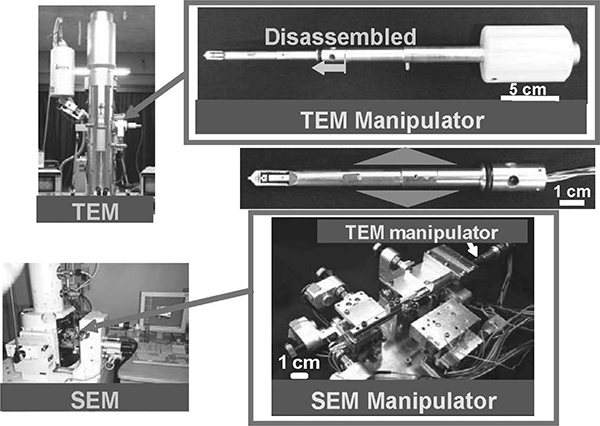
FIGURE 9.8
Photos of hybrid nanorobotic manipulation system inside a TEM and SEM.
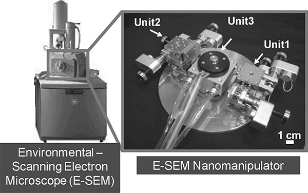
FIGURE 9.9
Photos of the nanorobotic manipulator inside an E-SEM.
Images of the yeast cells are shown with HV and E-SEM modes as shown in Figures 9.10a and 9.10b. The HV mode is operated with the conditions of room temperature (16. 7°C) and ~2. 0 x 10-3 Pa pressure. As shown in Figure 9.10a, almost all yeast cells show a concave and broken structure under HV mode. The E-SEM mode is operated with the conditions of 0. 0°C using a cooling stage and ~650 Pa pressure. The accreted voltage was set at 15 kV. In the E-SEM mode, when decreasing the pressure from ~700 Pa, the water, which is surrounding the cells, is gradually evaporated until showing up From Figure 9.10b, the remaining water can be seen in the intercellular spaces of yeast cells as black contrast Almost all of the yeast cells maintain their spherical shape in a water-containing condition with E-SEM operation.
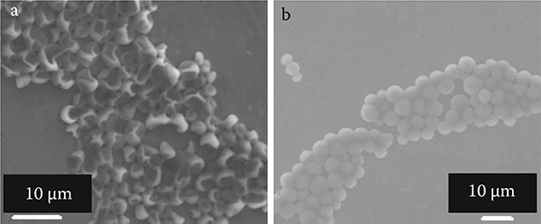
FIGURE 9.10
Electron microscopic images of yeast cells and culturing plate: (a) under HV mode and (b) under E-SEM mode.
To reveal the effect of observation with HV and E-SEM modes, the yeast cells were cultured again after observation The plate was divided into three regions: cultured after water dispersion, SEM observation (HV), and E-SEM observation. The number of yeast cell colonies in the E-SEM mode were greater than in HV mode. From this experiment, the living cell rate using E-SEM mode was almost the same order as that under initial conditions of water dispersion.
9.5 Stiffness Measurements of Single Cells Using Conventional AFM Cantilevers
9.5.1 Stiffness Measurement of Single Yeast Cells Depends on Cell Sizes
The single-cell stiffness measurement is presented using an E-SEM nanoro-botic manipulation system for yeast cells (Ahmad et al 2008a, 2008b) A schematic of experimental setup is presented in Figure 9.11. The yeast cells were fixed on the temperature-controlled stage in perpendicular direction with an AFM cantilever The position of the AFM cantilever was controlled by the nanomanipulator to apply the compression force on each cell The E-SEM can provide real-time observations, that is, a cell being approached, touched, indented, and finally penetrated/burst by the AFM cantilever, can be seen clearly The penetration of a single cell by the AFM cantilever was also measured from the occurrence of the cell bursting via real-time observation.
An E-SEM photo showing the penetration of single yeast cells is shown in Figure 9.12. The penetration forces clearly show a strong relationship between cell size and strength; the latter increases with an increase in cell size as shown in Figure 9.13. The average penetration forces for 3, 4, 5, and 6 pm cell diameter ranges are 96 ± 2, 124 ± 10, 163 ± 1, and 234 ± 14 nN, respectively.
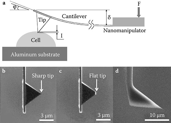
FIGURE 9.11
Schematic diagram of (a) an indentation experiment using (b) sharp and (c) flat AFM pyramidal cantilever tips under E-SEM mode. For the HV mode (d) a tetrahedral cantilever tip was used.

FIGURE 9.12
E-SEM photo during the penetration experiments of single yeast cells by an AFM cantilever tip: (a) sharp cantilever tip and (b) flat cantilever tip.
Yeast cell walls consist predominantly of glucan with (1,3)-ß and (1,6)-ß linkages and mannan covalently linked to protein (mannoprotein; Klis, Boorsma, and De Groot 2006; Lesage and Bussey 2006; Lipke and Ovalle 1998). Thus, it can be inferred that the ß-glucans composition increases when the yeast cell size increases. The average Young's modulus obtained in this work, that is, 3. 24 ± 0. 09 MPa, is reasonable compared to reported local cell stiffness values of 0. 73 MPa (Pelling et al. 2004) and 1.12 MPa (Lanero 2006), because the E values obtained in this chapter represent not only the local elastic property of the cell but the whole cell stiffness.

FIGURE 9.13
Penetration force using a sharp tip for different cell sizes. The curves are shown until the penetration points. Inner bracket () indicates the cell number for each cell size. Cell size is in micrometers.
9.5.2 Stiffness Measurement of Single Yeast Cells Depends on Growth Phases
All cells have a unique growth phase curve during their life cycle, which is normally divided into four phases: lag, log, saturation, and death phases. In the present study we did not investigate the death phase. These phases can be easily identified from the optical density (OD) absorbance-time curve. The lag phase is located at the initial lower horizontal line where the cells adapt themselves to growth conditions and the cells mature and divide slowly. The log phase can be seen from an exponential line where the cells have started to divide and grow exponentially. The actual growth rate depends upon the growth conditions The saturation phase resembles a final upper horizontal line where the growth rate slows and ceases mainly due to lack of nutrients in the medium. During the death phase, all of the nutrients are exhausted and the cells die (Tortora, Funke, and Case 2003). It is believed that the mechanics of normal cells have different properties in each of the phases. In this section, the mechanical properties of W303 yeast cells at four different growth phases (early, mid, late log, and saturation) are discussed (Ahmad et al. 2008b).
TABLE 9.1
Penetrate Forces of the Single Cells at Different Cell Growth Phases
Cell Growth Phase |
Penetrate Forces (nN) |
|---|---|
Early Log |
161 ± 25 (n-8) |
Mid Log |
216 ± 15 (n-9) |
Late Log |
255 ± 21 (n-8) |
Saturation |
408 ± 41 (n-8) |
The compression experiments were done from early log phase to saturation phase. Penetration force was analyzed for each phase as shown in Table 9.1. As expected, the force needed to penetrate a single cell increased from the early log to the saturation phase (161 ± 25, 216 ± 15, 255 ± 21, and 408 ± 41 nN), whereas the elastic properties of the cells appeared constant for all of the phases obtained; that is, 3. 28 ± 0. 17, 3. 34 ± 0. 14, 3. 24 ± 0. 11, and 3. 38 ± 0. 11 MPa.
These mechanical properties of the W303 yeast cells at different growth phases are in agreement with reported increments of average surface modulus of Saccharomyces cerevisiae cell walls as 11. 1 ± 0. 6 N/m (log phase) and 12.9 ± 0. 7 N/m (saturation phase) with no significant increase in the elastic modulus of the cell; that is, 112 ± 6 MPa (log phase) and 107 ± 6 MPa (saturation phase; Smith et al. 2000). Their values for elastic modulus are quite high is reasonable because they measured the whole elastic properties of the cell by compressing a single cell between two big flat indenters compared to local cell indentation in our case
9.6 Stiffness Measurements of Single Cells Using Nanoprobes
9.6.1 Fabrication of Nanoprobes
Four kinds of nanoprobes were fabricated using a focused ion beam (FIB) process at the tip of AFM cantilevers as shown in Figure 9.14. Standard plati-num-coated tetrahedral cantilever tips with a spring constant of 2 N/m were used in the fabrication of Si, Si-Ti, and tungsten nanoprobes For the tungsten nanoprobe, a standard sharp pyramidal cantilever tip with a 0 09 N/m spring constant was used The soft Si nanoprobe was fabricated by etching (Figure 9.14a). The first type of hard nanoprobe, that is, an Si-Ti nanoprobe, was fabricated by coating the former Si nanoprobe with Ti material by sputtering (Figure 9.14b). The second type of hard nanoprobe was fabricated by first flattening the apex of the sharp pyramidal cantilever tip by using FIB etching (Figure 9.14c). Another type of tungsten hard nanoprobe was fabricated by first flattening the apex of the sharp tetrahedral cantilever tip using FIB etching, followed by tungsten deposition of a large area using FIB deposition, and finally trimmed to produce the nanoprobe structure using FIB etching (Figure 9.14d).
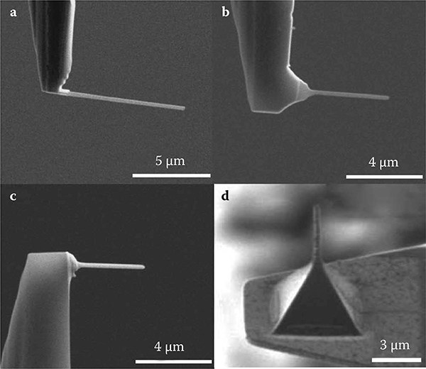
FIGURE 9.14
Actual images of (a) Si, (b) Si-Ti, (c) and (d) tungsten nanoprobes.
9.6.2 Calibration of Soft Nanoprobes
The Young's modulus and spring constant of the soft Si nanoprobe, Eneedle and kneedle, were calibrated using a nanomanipulation technique. The soft nanoprobe was slowly pressed against another cantilever tip to experimentally determine the spring constant (0 110 N/m) The indentation was carried out until the nanoprobe begun to buckle Then, the buckled nanoprobe was slowly retracted until the nanoprobe returned to a straight condition as shown in Figure 9.15. The value of Eneedle was determined from the Euler buckling equation as shown in Equation (9.18), where lbuckle is the length of the soft nanoprobe during the buckling condition
(9.18)
where Fn is the buckling force applied to the nanoprobe; Eneedle is the Young's modulus of the nanoprobe; I is the second moment of area; K is the nano-probe effective length factor, whose value depends on the conditions of the end support of the nanoprobe; and I is the length of the nanoprobe. The value of the length of the soft nanoprobe was corrected with K = 0.8 for a structure that has one fixed end and the other end pinned (Timoshenko and Gere 1961). I is a property of a shape that is used to predict its resistance to buckling A soft nanoprobe that has a rectangular cross section has the value of I = (wb3)/12, where w and b are the width and height of the rectangular cross section. The values for w and b, which were obtained from an image analysis, were 165 and 170 nm, respectively.
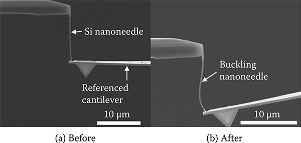
FIGURE 9.15
Calibration of the Si nanoprobe (a) before buckling and (b) after buckling.
9.6.3 Stiffness Measurement of Single Yeast Cells by Nanoprobes
The whole stiffness response of a single cell, that is, the deformation of the entire cell upon the applied load from a single point indentation, to the best of our knowledge, has not been previously reported. The difficulty in obtaining such data is due to the stiff indenter, which may penetrate or burst the cell Our soft nanoprobe can be used to prevent cell penetration by its ability to buckle during indentation The mechanism of cell deformation is stated as follows: upon indentation of the soft nanoprobe on the cell, local deformation occurs below the tip of the nanoprobe Further indentation induces the whole cell to deform in addition to the local cell deformation The ability to produce a large local point indentation could provide more information regarding the mechanical property of the organelles inside the cell. The global stiffness measurement of single cells from single point indentation was performed using an Si nanoprobe as shown in Figure 9.16. The measurement was performed using a standard indentation procedure The Si nanoprobe started to buckle after the cell deformed about 0.5 urn. From this point, the buckling rate of the Si nanoprobe increased with increased indentation depth. The values of kcell for approximately the same physical parameters of two yeast cells, that is, 0 92 ± 0. 12 and 0.95 ± 0.36 N/m, show strongly similar mechanical properties.
The values that represent the whole cell spring constants are reasonable compared to the reported local spring constant of the S. cerevisiae yeast cell (0.06 ± 0.025 N/m). The values of whole Ecell; that is, 3.64 and 3.92 MPa, are also rational because they represent the whole cell stiffness property compared to the reported local Young's modulus of the yeast cell; that is, 0.72 ± 0.06 MPa (Pelling et al. 2004). Our method shows improved data sensitivity compared to other global stiffness measurement methods that rely on compression of a single cell between one large indenter and a substrate. Data from this method may not represent the actual global cell stiffness because extra dissipation force may be included in the measurement as reported by Smith et al. (2000) for the global cell spring constant and Young's modulus of yeast cell as 11.1 N/m and 112 MPa.

FIGURE 9.16
Single-cell global stiffness measurement from a single point using an Si nanoprobe. Two images show the Si nanoprobe in (a) a straight condition and (b) buckling condition.
9.7 Summary
In this chapter nanorobotic nanomanipulation inside electron microscopes was presented. An E-SEM nanomanipulation system was used to observe and manipulate biological samples in nanoscale resolution. The system can be used for various applications for the direct observation and manipulation of biological samples with nondrying, nondyeing, noncoating treatments, with a 7-DOF nanomanipulator with a sharp pyramidal end-effector and a cooling stage; that is, a temperature controller. We demonstrated in situ measurements of mechanical properties of individual W303 wild-type yeast cells using several types of nanoprobes. Compression experiments to penetrate the cell walls of single cells of different cell sizes (about 3-6 um diameter) and growth phases (early log, mid log, late log, and saturation) were con-ducted. Data clearly show an increment in penetration force; that is, 96 ± 2, 124 ± 10, 163 ± 1, and 234 ± 14 nN for 3, 4, 5, and 6 um cell diameters, respectively. This was further confirmed from quantitative estimation of average cell rigidity through the Hertz model. The penetration forces at different cell growth phases also show the increment pattern from log (early, mid, and late) to saturation phases; that is, 161 ± 25, 216 ± 15, 255 ± 21, and 408 ± 41 nN, respectively
The advantage of the integrated E-SEM nanomanipulation system relies on its capability to perform in situ local direct observation and manipulation of biological samples and its ability to control environmental conditions
Acknowledgments
We thank Professors Michio Homma, Seiji Kojima, and Masaru Kojima at Nagoya University for discussion of biological aspects and Professor Toshifumi Inada at Nagoya University for providing us with the wild-type yeast strain W303 cells for the experiments This work was partially supported by a Grant-in-Aid for Scientific Research from the Ministry of Education, Culture, Sports, Science and Technology of Japan and COE for Education and Research of Micro-Nano Mechatronics, Global COE Program of Nagoya University
References
Ahmad, M. R., Nakajima, M., Kojima, S., Homma, M., and Fukuda, T. 2008a. In situ single cell mechanics characterization of yeast cells using nanoprobes inside environmental SEM, IEEE Transactions on Nanotechnology, Vol. 7, pp. 607-616.
Ahmad, M R, Nakajima, M., Kojima, S., Homma, M., and Fukuda, T 2008b The effects of cell sizes, environmental conditions and growth phases on the strength of individual w303 yeast cells inside ESEM. IEEE Transactions on Nanobioscience, 7: 185-193.
Ahmad, M R, Nakajima, M., Kojima, S., Homma, M., and Fukuda, T 2010 Nanoindentation methods to measure viscoelastic properties of single cells using sharp, flat, and buckling tips inside ESEM. IEEE Transactions on Nanobioscience, 9(1): 12-23.
Aksu, S. B. and Turner, J. A. 2007. Calibration of atomic force microscope cantilevers using piezolevers. Review of Scientific Instruments, 78: 1-8.
Avery, S.V. 2006. Microbial cell individuality and the underlying sources of heterogeneity. Nature Reviews: Microbiology, 4: 577-587.
Craighead, H.G. 2000. Nanoelectromechanical systems. Science, 290: 1532-1535.
Dao, M., Chollacoop, N., Van Vliet, K.J., Venkatesh, T.A., and Suresh, S. 2001. Computational modelling of the forward and reverse problems in instrumented sharp indentation. Acta Materialia, 49: 3899-3918.
Du, E., Cui, H., and Zhu, Z. 2006. Review of nanomanipulators for nanomanufactur-ing. International Journal of Nanomanufacturing, 1: 83-104.
Ferrell, J. E. and Machleder, E. M. 1998. The biochemical basis of an all-or-none cell fate switch in Xenopus oocytes. Science, 280: 895-898.
Feynman, R.P. 1960. There's plenty of room at the bottom. Caltech's Engineering and Science, 23: 22-36.
Fukuda, T., Arai, F., and Dong, L.X. 2003. Assembly of nanodevices with carbon nanotubes through nanorobotic manipulations. Proceedings of the IEEE, 91: 1803-1818
Hell, S. W. 2007. Far-field optical nanoscopy. Science, 316: 1153-1158.
Hertz, H. 1882. On the contact of elastic solids. Journal für die Reine und Angewandte Mathematik, 92: 196-171.
King, R B 1987 Elastic analysis of some punch problems for a layered medium International Journal of Solids and Structures, 23: 1657-1664.
Klis, F M, Boorsma, A., and De Groot, P W J 2006 Cell wall construction in Saccharomyces cerevisiae. Yeast, 23: 185-202.
Lanero, T S 2006 Mechanical properties of single living cells encapsulated in poly-electrolyte matrixes. Journal of Biotechnology, 124: 723-731.
Lanero, T S, Cavalleria, O., Krol, S., Rolandi, R., and Gliozzi, A 2006 Mechanical properties of single living cells encapsulated in polyelectrolyte matrixes Journal of Biotechnology, 124: 723-731.
Leary, S. P., Liu, C. Y., and Apuzzo, M. LJ. 2006. Toward the emergence of nanoneuro-surgery: Part III—Nanomedicine: Targeted nanotherapy, nanosurgery, and progress toward the realization of nanoneurosurgery. Neurosurgery, 58: 1009-1026.
Lesage, G and Bussey, H 2006 Cell wall assembly in Saccharomyces cerevisiae Microbiology and Molecular Biology Reviews, 70: 317-343.
Lewis, A., Taha, H., Strinkovski, A., Manevitch, A., Khatchatouriants, A., Dekhter, R., and Ammann, E. 2003. Near-field optics: From subwavelength illumination to nanometric shadowing. Nature Biotechnology, 21: 1378 -1386.
Lipke, P. N. and Ovalle, R. 1998. Cell wall architecture in yeast: new structure and new challenges. Journal of Bacteriology, 180: 3735-3740.
Mendels, D -A, Lowe, M., Cuenat, A., Cain, M G, Vallejo, E., Ellis, D., and Mendels, F. 2006. Dynamic properties of AFM cantilevers and the calibration of their spring constants. Journal of Micromechanics and Microengineering, 16: 1720-1733.
Nakajima, M., Arai, F., and Fukuda, T 2006 In situ measurement of Young's modulus of carbon nanotube inside TEM through hybrid nanorobotic manipulation system IEEE Transactions on Nanotechnology, 5(3): 243-248
Pelling, A E, Sehati, S., Gralla, E B, Valentine, J S, and Gimzewski, J K 2004 Local nanomechanical motion of the cell wall of Saccharomyces cerevisiae Science, 305: 1147-1150
Pharr, G M, Oliver, W C, and Brotzen, F R 2002 On the generality of the relationship among contact stiffness, contact area, and elastic modulus during indentation Journal of Materials Research, 7: 619-617.
Sader, J E 1995 Parallel beam approximation for V-shaped atomic force, microscope cantilevers. Review of Scientific Instruments, 66: 4583-4587.
Sedgwick, H., Caron, F., Monaghan, P. B., Kolch, W., and Cooper, J.M. 2008. Lab-on-a-chip technologies for proteomic analysis from isolated cells Journal of the Royal Society Interface, 5: S123-S130.
Smith, A E, Zhang, Z., Thomas, C R, Moxham, K E, and Middelberg, A P J 2000 The mechanical properties of Saccharomyces cerevisiae. Proceedings of the National Academy of Sciences, 97: 9871-9874.
Sneddon, I N 1965 The relation between load and penetration in the axisymmet-ric Boussinesq problem for a punch of arbitrary profile. International Journal of Engineering Science, 3: 47-57
Staples, M., Daniel, K., Sima, M J, and Langer, R 2006 Applications of micro- and nano-electromechanical devices to drug delivery Pharnaceutical Research, 23: 847-863.
Stephen, N G 2007 Macaulay's method for a Timoshenko beam International Journal of Mechanical Engineering Education, 35: 285-292.
Timoshenko, S.P. and Gere, J.M. 1961 Theory of Elastic Stability (2nd ed) New York: McGraw-Hill.
Tortora, G.J., Funke, B.R., and Case, C L 2003 Microbiology: An Introduction (8th ed) San Francisco, CA: Benjamin Cummings.
Wilson, J and Hunt, T 2002 Molecular Biology of the Cell New York: Garland Publishing.