
6
Development of a Low-Noise Bio-Inspired Humanoid Robot Neck
Bingtuan Gao
Southeast University Nanjing, China and
Michigan State University East Lansing, Michigan
Ning Xi, Jianguo Zhao, and Jing Xu
Michigan State University East Lansing, Michigan
CONTENTS
6.2 Low-Motion-Noise Robotic Head/Neck System
6.2.3 Programming Head Movements
6.3 Inverse Kinematics and Statics Analysis
6.3.2 Cable and Housingnoindentc
6.5.1 Experimental Setup and Motion Control of the Robotic Neck
Abstract
A humanoid neck system that can effectively mimic the motion of a human neck with very low motion noises is presented in this chapter The low-motion-noise humanoid neck system is based on the spring structure and is cable driven, which can generate 3 degrees of freedom of neck movement To guarantee the low-noise feature, no noisemak-ers like motors, gearboxes, and electrodriven parts are embedded in the head-neck structure Instead, the motions are driven by six polyester cables, and the actuators winching the cables are sealed in a sound insulation box Statics analysis and control strategy of the system is discussed Experimental results clearly show that the head-neck system can greatly mimic the motions of human head with an A-weighted noise level of 30 dB or below
6.1 Introduction
The use of donning respirators or chemical-resistant jackets for some emergent conditions or during performing some special tasks is required. Most current donning respirators or chemical-resistant jackets unavoidably generate acoustic noises when the user moves his head/neck These noises strongly interfere with the user's hearing even when using head-worn wireless communication equipment. Thus, it is necessary to develop a testing wearable audio system Many companies have created systems for testing headphones and cell phones such as KEMAR manikins (G.R.A. S. Sound & Vibration, www.gras.dk). But the movements of the manikins are very limited and cannot be used to test the interaction of the audio system with other systems such as overcoats This chapter will focus on the design and control of a low-noise biomimetic humanoid neck system, which can be used to investigate the level of acoustic noises produced by the interactive motion between wearable equipment and the human head/neck to facilitate the use of head-worn communication devices
Although many humanoid neck mechanisms have been developed by different institutions, they can be divided into two categories; that is, the serial neck and parallel neck Serial necks are the more common mechanisms due to their simple structure and the ease of DC motor control The HRP-2 (Hirukawa et al. 2004) has a two-degrees-of-freedom (DOF) serial neck including pitch and yaw. The Albert HUBO (Park et al. 2008), the Dav (Han et al. 2002), and the iCub (Beira et al. 2006) have 3-DOF serial necks. The WE-4 (Miwa et al. 2002), the ARMAR-III (Albers et al. 2006), the WABIAN-RIV (Carbone et al. 2006), and the ROMAN (Hirth, Schmitz, and Berns 2007) have 4-DOF serial necks The parallel neck can be divided into three subcat-egories; that is, Stewart-like necks, spring-based necks, and spherical necks The main structure of Stewart-like necks is a Stewart platform (Beira et al 2006), which needs a passive spine and is controlled by several legs with a combination of universal, prismatic, and spherical joints The actuators for the parallel necks can be DC motors or pneumatic cylinders Parallel mechanisms have the characteristics of rigidity, high load capacity, and high precision; however, it is hard to achieve a large range of motion and they are not suitable for use in limited neck space The motion of a spherical neck is based on a spherical joint Using screw theory, Sabater et al (2006) designed and analyzed a spherical humanoid neck A spring neck uses a spring as the spine to support the head and facilitate its motion A spring neck is usually driven by motors (Beira et al. 2006; Nori et al. 2007) and artificial muscles (Hashimoto et al 2006) According to previous investigations, a spring neck is similar to a real human neck and it is economical to build; however, it is hard to achieve high precision positioning control because of the complicated dynamics of the springs
Most of the research on humanoid robotic necks provides insight into how to make the neck move similar to a real human neck However, little research has adequately addressed how to design a robotic neck that can move quietly. Inspired by the human neck structure (White and Panjabi 1990), the main part of the developed head/neck is a compressed column spring that has a similar function to that of the spine. It supports the artificial/robotic head and can bend around the neutral axis to generate 2-DOF rotation including pitch and roll motions (bending of the head forward and backward and left and right, respectively) A cable-pulley structure mounted above the spring is used to realize the yaw motion (rotating the head to the left and right) The 3-DOF motion of the neck is realized through six cables that have similar functions of human neck muscles These cables are pulled by the actuators sealed in a sound insulation box Because no sound generation parts are embedded into the robotic neck, only very low motion noises are generated
6.2 Low-Motion-Noise Robotic Head/Neck System
6.2.1 System Overview
The structure of the developed robotic system is shown in Figure 6.1. The system consists of three main parts: a humanoid robotic unit, a sound insu-lation box, and a personal computer The robotic unit has a movable robotic head, a torso, and a height-adjustable support frame used to match humans of different heights either sitting or standing The size of the head and torso is designed based on the head size of a human adult so that a full-size personal protective uniform fits the robotic system well. The movable robotic head has a 3-DOF neck framework to mimic human neck movements These movements are driven by the remote motor-based actuators installed in the sound insulation box through the compound cable-and-housing group The motor-based actuators are controlled by a PC via a peripheral component interconnect (PCI)-based motion controller board, and the control/driven strategy of the motor system is developed and conducted using the PC. Two Omni microphones are installed in the robot head to mimic human ears that can collect the sound information around the robot head effectively. Sensors embedded in the robot neck are capable of measuring its absolute rotation along three orthogonal axes. Signals from the microphones and sensors are collected by the PC through two USB-based data acquisition boards. The main task is to design and develop a humanoid head, sound insulation box, and PC-controller system
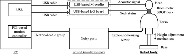
FIGURE 6.1
Overview of the robot system.
In the system, cable housings are used to guide the drive cables or to transmit the outputs of actuators from the sound insulation box to the robot head We found at least three advantages for utilizing a cable-and-housing group in this system: (1) it simplified the mechanical transmission design significantly, (2) few noises were generated by the cable-and-housing group, and (3) it facilitated the sealing issue for the sound insulation box The materials of the drive cables are braided polyester The housings are typical bicycle brake cable housings Because the innermost layer is lubricated in the cable housing, the friction coefficient is relatively low between the cable and its housing It should be noted that the steel drive cables can transmit noise outside of the sound insulation box, in which motors, gearboxes, and corresponding electrical parts are installed, to the robotic head/neck
6.2.2 Hardware Development
The computer assisted design (CAD) assembly model of the 3-DOF robotic neck is shown in Figure 6.2. A compressive spring connecting two plates serves as the main mechanical structure of the robotic neck. The fixed plate is mounted onto the torso and the movable plate together with all parts mounted on it can be bent by the four symmetrically distributed drive cables Thus, the movable plate can realize 2-DOF rotation including pitch and roll (the single-axis motions corresponding to the head motions flexion, extension, bending left, and bending right). As shown in Figure 6.2, four small pulleys mounted on the bottom surface of the movable plate are used to enhance the bending force exerted by the four cables. Note that one end of the four cables is fastened to the fixed plate. These four cables are guided to the robotic neck by their cable housings, and one end of the cable housing is also fastened to the fixed plate.
The yaw motion of the robotic head mimicking a human head's yaw motion can be achieved by using a cable-and-pulley structure, which is connected to the movable plate via a shaft and ball bearing group As a result, the yaw motion of the robotic head is designed to be realized by the structure located on the top of the robotic neck This design is in accordance with the fact that most of the yaw motion of a human head is generated between the C1 and C2 cervical vertebrae (White and Panjabi 1990). The shaft and ball bearing group in the structure can effectively reduce the friction and motion noises of the rolling shaft during the yaw motion. Because the cable housings used to guide the yaw drive cables cannot be mounted with a small curvature radius within the small space between the movable slate and the pulley, they are fixed into the movable plate. Instead, two small pulleys are used to guide the two cables to realize yaw motion
In addition, two sensors for monitoring the motion of the 3-DOF neck are used, as shown in Figure 6.2. One is a two-axis inclinometer that measures the pitch and roll angles and is mounted on the top surface of the movable plate The other is a potentiometer for measuring the yaw motion angle The shaft of the potentiometer is fixed with the yaw pulley through the shaft and bearing group. Two Omni microphones for collecting the acoustic information around the robot head are embedded into the two ears of the robotic head
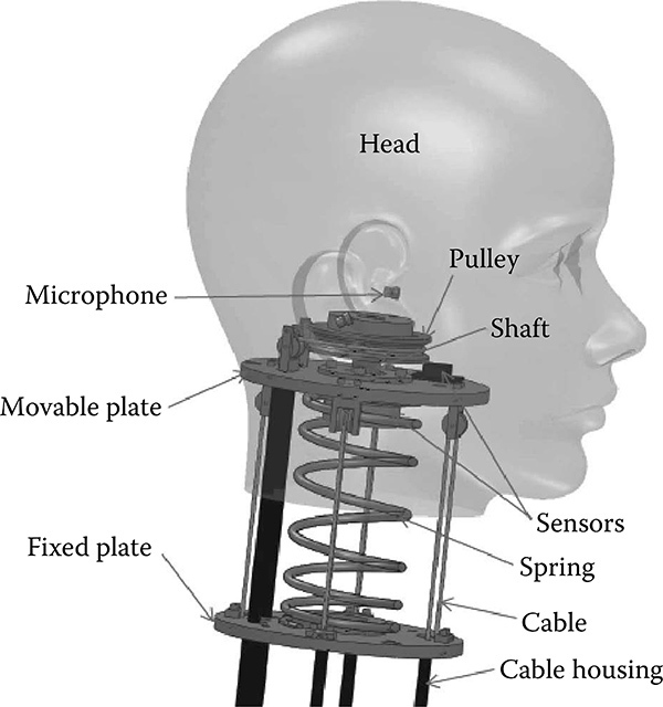
FIGURE 6.2
CAD assembly model of 3-DOF robotic neck.

FIGURE 6.3
Overview of the sound insulation box.
The sound insulation drive box is an important part of the whole system. The noisy parts such as motors and their gearboxes are installed in the sealed space within the box. An overview of the sound insulation box can be seen in Figure 6.3. There is a mounting frame with two layers; that is, two mounting plates connected by rods. On the top plate, power supplies, motor drivers, a power switch, fuses, and other electrical parts are mounted and the motor-based drive mechanisms are mounted on the bottom plate The drive cables are wound and unwound by pulleys connected to the output shafts of the gearboxes. The other ends of the cable housings are fixed to the mounting frame The drive cables within the housings and electrical cables are guided out of the box in bunches through two well-sealed holes in the side walls of the box
There are two ways to passively eliminate the noise One is sound insulation and the other is sound absorption. Sound insulation eliminates the sound path from a source. Usually high-density materials are the best choice for sound insulation. Sound absorption works when some or all of the incident sound energy is either converted into heat or passes through an absorber such as porous foams To prevent sound transmission from the box, sound insulation and sound absorption techniques are both adopted. As shown in Figure 6.3, the box itself is made of a heavy, 12-gauge cold-rolled steel with a sound insulation technique. The six inner walls of the box are covered by 10-mm-thick butyl rubber, which has good acoustic absorption effects The rubber helps to absorb the noises with frequencies between 30 and 4,000 Hz. The mounting frame is actually floated in the box, and between the butyl rubber on the bottom wall of the box and the mounting frame, an anti-vibration pad is employed to isolate the sound propagation paths
In summary, because (1) no noisy gears and electrodriven parts are embedded in the biomimetic head/neck structure, (2) sound generation parts are sealed in the sound insulation box, and (3) the drive system is dominated by the low-friction and highly efficient cable-and-housing group, the humanoid head/neck system can mimic well the motion of a human head without generating unacceptable motion noises
6.2.3 Programming Head Movements
The 3-DOF neck motion can fulfill six single movements including head flexion, head extension, bending head left, bending head right, rotating head left, and rotating head right The instructions for each movement have two programmable parameters: movement range and movement time. In other words, the position and velocity of each movement can be defined. All non-conflicting multi-axis combined movements and sequences of movements are able to be performed by the robotic system This means that all complex movements associated with a human neck can be conducted by the robotic head/neck
6.3 Inverse Kinematics and Statics Analysis
6.3.1 Neck Mechanism
A general configuration of the spring-based, cable-driven mechanism corresponding to Figure 6.2 is shown in Figure 6.4, in which Figures 6.4a-c show the parallel mechanism of pitch and roll motions, general lateral bending of the compressive spring, and yaw motion by the rotating pulley, respectively The yaw motion driven by two cables as shown in Figure 6.4c is straightforward; thus, we are mainly interested in analysis of the parallel mechanism and compressive spring
As shown in Figure 6.4a, a fixed coordinate frame OXYZ is attached to the fixed plate, with the origin at the bottom center of the spring, and a body frame oxyz is attached to the moving plate, with the origin at the top center of the spring. Four flexible cables with negligible mass and diameter are connected to the moving platform at points Bi (i = 1, 2, 3, 4) and pulled from the base plate at point Ai. Denote the force value along the cable as Ti and the cable length between two plates as li . ui is the unit vector for the force direction pointing to the base plate, thus Tiui =Ti. The compressive spring produces a force/torque between the fixed base and the moving platform to support the robot head and facilitate the head motion If the cables are actuated, the spring will bend in a plane formed by O, o, and o' where o' is the vertical projection of o onto the fixed base. In this plane, a planar body frame Oph is attached to this spring.
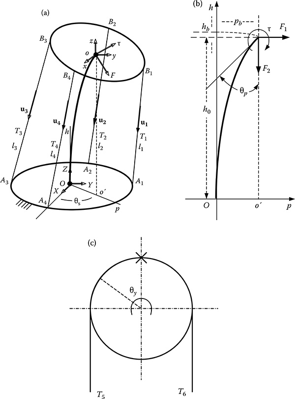
FIGURE 6.4
General configuration of the neck mechanisms: (a) configuration of the parallel mechanism for pitch and roll motions, (b) configuration of lateral bending of the compressive spring, and (c) configuration of the yaw motion by the rotating pulley
This parallel mechanism has 3 DOF: the vertical translation DOF and two rotational DOFs. For the rotational DOFs, we use 8s and 8p to parameterize them where 8s is the rotation direction and 8p is the rotation amplitude. For the vertical DOF, we use h0 to denote the coordinate in frame Oph. For the inverse kinematics, we want to obtain the driven cable length given the desired DOF value. Thus, the inverse kinematics is to find the mapping f :(Os,Op, k0 ) — l2, l3, l4). However, unlike traditional parallel mechanism, this is not trivial because of the dependent motion characteristic of the spring bending, which in turn is related to the static force along the cables. Therefore, we should combine the inverse kinematics and statics in order to obtain a solution
By the equivalence of force systems, all of the forces along the four cables can be transformed into the bending plane Oph; otherwise, the spring will not bend in that plane. Therefore, we convert all of the forces to two perpendicular forces F1 and F2, and a momentum t at the top center of the spring in the plane as shown in Figure 6.4b. For the force and momentum balance, we have:
(6.1)
(6.2)
where ri corresponds to the vector expressed in the fixed frame OXYZ and the unit vector ui can be expressed as
(6.3)
We take the compressive helical spring as a flexible bar to investigate lateral bending characteristics of the spring, but it is necessary to consider the change in length of the spring due to compression, because the change is not negligible in the case of compressed bars (Timoshenko 1936). Consider the practical lateral bending of the neck as in Figure 6.4b. The spring-based mechanism will be bent by forces F1 and F2 plus t . Because the motion of the head is usually no more than 15 degrees buckled in all roll, pitch, and yaw axes (Sterling et al. 2008), it is feasible to use a linear equation to calculate the statics model of lateral bending for the cable-driven robotic head/neck in this application:
(6.4)
where ß is the flexural rigidity of the spring under compression, and it is inversely proportional to the number of coils per unit length of the spring (Timoshenko 1936); hence,
where fi0 is the original length of the spring, and ß0 can be calculated based on physical parameters of the compressive spring The initial conditions at the two ends of the spring are
(6.5)
By neglecting the corresponding vertical displacement hb of the spring under small bending, as shown in Figure 6.4b, the spring length under compression is calculated as
(6.6)
where K is the spring stiffness and L0 is the initial length of the spring.
Based on Equations (6.1)-(6.6), for a configured cable-driven, spring-based parallel mechanism as shown in Figures 6.4a and 6.4b, both the inverse kinematics and statics can be solved analytically
6.3.2 Cable and Housing
The drive cable used in this application is braided extra-strength polyester twine Because the length of the drive cable is longer than 2 m, the extension of the cable has to be considered While a cable is pulled in a curved housing, friction force is unavoidable. Here it is assumed that the shape of the cable and housing is unchanged for each robot motion control, and we can depict a cable and housing with n turns as shown in Figure 6.5.
The coefficient of static friction and kinetic friction between the cable and the inner wall of its hose is taken as the same u. Each turn in the curving path can define a plane and we define the hose bends counterclockwise away from the velocity of the cable as its turn angle A¡ . As in this application, the turn angles are defined as A j e [0,2n] n, j = 1, ?, n. We use Fj and lj to denote the cable force and hose length of each segment. Note that the j here is in [1, n -1]. The F0 and Fn are the input driving force and output driving force of the cable-hose drive mechanism The l0 denotes the cable length measured from a fixed point of the output of the motor to the first turn of the hose and ln denotes the cable length measured from the last turn of the hose to a fixed point on the robot head.

FIGURE 6.5
Sketch of the cable and housing.
Because the diameter of the drive cable is very close to the inner diameter of the cable hose, we take the turn angles of the cable as the same as the turn angles of the cable hose. The relationship between the input force and output force in each segment can be derived as
Based on the developed relationship, we can obtain the relationship between the input force and output force for a given drive cable-and-housing path
(6.8)
In this case, when the friction coefficient and turn angles are known, we can calculate the input force and output force when one of them is given
The cable will be extended like a spring with stiffness constant k when a force is applied on it Therefore, the absolute extended length of the cable will be
(6.9)
Finally, we state the overall inverse kinematics from the head position to the cable winding/ unwinding pulley. For given motion task parameters (8S, Qp, h) , the cable length li and exerted cable force Ti, which is equivalent to the output force Fout, can be calculated based on Equations (6.1)-(6.6). The overall elongation length of each cable can be found based on the cable-and-housing model once the cable drive paths are given Finally, the cable length needed to be wound/unwound by driving winches can be determined
6.4 Control Strategy
6.4.1 Rigidity Maintenance
It is well known that cables can only generate pull force This unilateral force constraint in drive cables has to be incorporated into the design and control procedure; otherwise, the cable-based manipulator may collapse. Therefore, maintaining positive tension (tensile force) in all of the cables is an essential requirement for the rigidity of a cable-based manipulator. Because the rigidity of a cable-based manipulator depends on the external load, it is complicated to analyze. To overcome this problem, Behzadipour and Khajepour (2006) employed tensionability, which only depends on the geometry to express the potential of the manipulator to be rigid. The tensionability is defined as: a cable-based mechanism is called tensionable at a given configuration of the movable platform if and only if for any arbitrary external load there exists a finite spine force/torque and a set of finite cable tensions to make the mechanism rigid. As a result, tensionability and large enough tensile force together provide a sufficient condition for the rigidity.
According to the static analysis in the last section, for an arbitrary positive spine force F and torque t, the static equilibrium Equations (6.1) and (6.2) have a solution with all positive cable tensions T (i = 1, 2, 3, 4). This implies that the robot head can be statically balanced (in pitch and roll DOF) under an arbitrary compressive spring force/torque. Consequently, it is tension-able and thus can stay rigid for any external force and torque with a large enough precompressed force/torque To maintain the rigidity of the robotic head, different personal protective equipment (PPE) and their combinations as an external payload were studied together with the robotic head itself to derive the potential maximum spine force/torque (compressive force/torque of the spring). In other words, the length of the spring needed to be precom-pressed by the drive cables is enough to maintain the rigidity of the robotic head when different PPEs or their combinations are put on the head In this way, we decide h0 as in Figure 6.4 during the implementation. A bang-bang control algorithm is employed to achieve the precompressive process at the beginning of the robotic system's operation.
6.4.2 Motion Control
Although 3-DOF human head motions are always coupled, we divided the robotic head motions into two categories depending on the number of active axes in a motion: single axis motion and multi-axis motion, such as looking down and forward (flexion) and down and to the left (flexion and rotation left). We divided the robotic head motions into two categories based on the motion continuity: single motion and continuous motion, such as looking down and forward (flexion) and nodding (flexion back and forth). Before the motion execution, it is necessary to transform a continuous motion to a series of single motions and map a multi-axis motion into simultaneous single-axis motions
Based on the movement characteristics of the human head, moving smoothly other than positioning accuracy is the first priority of the each movement Because the robot will be used to collect the noises generated by the PPE during human head/neck movements, continuous motion is performed more frequently. For each single movement, two parameters are given as described in Section 6.2; that is, range of movement and movement time. By considering the initial position of the robotic head, trapezoidal velocities of the robotic head movement can be generated According to the analysis in Section 6.3, these trapezoidal velocities are transformed into the cable length needed to be wound or unwound. Using this open-loop control, it is hard to achieve accurate positioning control due to the unmodeled parameters and disturbances To ensure the positioning control of the robotic head, at the end of the motion, a simple bang-bang controller
is employed to locate the robot head at the right destination, where ve is the execution velocity, v0 is a small velocity value, and s is a prescribed position error threshold
6.5 Implementation
6.5.1 Experimental Setup and Motion Control of the Robotic Neck
The low-motion-noise humanoid head/neck system developed as described in Section 6.2 is pictured in Figure 6.6. Figure 6.6a shows the overall system. In the system, an NI USB-6215 multifunction I/O board is used to acquire the sensor data and collect information to monitor the working status of electrical parts in the sound insulation box. An M-Audio interface, USB-based Fast Track Pro, is used to record the acoustic information obtained by two sensitive microphones in the robot ears during the motion of the robotic head/ neck For one of the applications, the robot body and the sound insulation box are located in one acoustic room, and the personal computer, the NI USB-6215, and M-Audio interface are located outside of the room to avoid inducing other acoustic noises. Real PPEs such as helmets, masks (respirators), and chemical-resistant suits were employed in our experiments These PPEs were equipped with the robotic head/neck system for our further studies on acoustic noise induced by motion between the PPEs and the robotic system
Single and combination head motions have been implemented successfully on the developed robot system Typical single head movements dem-onstrated in Figure 6.6b are: flexion, extension, bending left, bending right, rotating left, and rotating right And motion parameters of the developed robotic neck system are listed in Table 6.1.
6.5.2 Motion Noise Test
An anechoic chamber at Michigan State University was used as an acoustic room to test the noise level of the robotic head/neck system during its motion The noise level of the system during its motions was monitored by a sound level alert from Extech Instruments A picture of the noise level testing experiment is shown in Figure 6.7a. The experimental results showed that the maximum noise level of the system during different motions was no more than 30 dB A-weighted
To compare the different noise generation between the motions of the robot head without and with PPE, another experiment was done in a common lab environment, where several computers and the air-conditioning system were running The head executed a rotating left right (like shaking) motion for 17 seconds, and the PPE selected was a plastic jacket hood The steps for audio calibration and recording were as follows: (1) place speaker 1 m away from the robot ears (microphones); (2) play a 1-kHz standard tone for 28 seconds; (3) adjust the tone volume so that when placed near each microphone, a sound level meter measures a sound level of 60 dB; (4) without changing the microphone gain settings, start to record the acoustic data generated by the robot's motion without PPE; (5) record the acoustic data generated by the same robot motion with a plastic jacket hood A picture of the audio calibration procedure is shown in Figure 6.7b, and the recorded acoustic data were combined and are shown as Figures 6.7c and 6.7d. As we can see from the acoustic recording results, the characteristics of the noise generated by the PPE are distinct and easy to extract and analyze with the help of the low-motion bio-inspired humanoid neck

FIGURE 6.6
Pictures of the robotic system developed and its typical movements: (a) the overall system and (b) instructions for six typical movements.
TABLE 6.1
Motion Parameters of the Robotic Head Developed
Movements |
Range |
Maximum Velocity |
Bending left/right |
30°/30° |
150°/s |
Flexion/extension |
30°/45° |
150°/s |
Rotating left/right |
60°/60° |
200°/s |
6.6 Summary
This chapter presents our recently developed 3-DOF humanoid neck system that can effectively mimic motion of human neck with very low motion noises. Three main ideas are fulfilled to reduce noise as follows: (1) a compressive helical spring to mimic the cervical vertebrae and cables to mimic muscles, which means there are no gears and electrodriven parts that make noise, are embedded in the head/neck structure; (2) a remotely driven head/neck system using a cable-and-housing group, which guarantees low friction and low noise transmission; and (3) the noisy cable-pulling actuators are sealed in a sound insulation box To validate the design of the system, both theoretical statics analysis and experiments were implemented The experimental results prove the effectiveness of the head/neck system designed The system can be effectively used to investigate the level of acoustic noises produced by the interactive motion between wearable equipment/uniforms and a human head/neck to facilitate using head-worn communication devices
Acknowledgment
The authors thank Qi (Peter) Li, Uday Jain, and Josh Hajicek from Li Creative Technology, Inc, for helpful discussions on the robots.
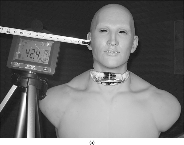
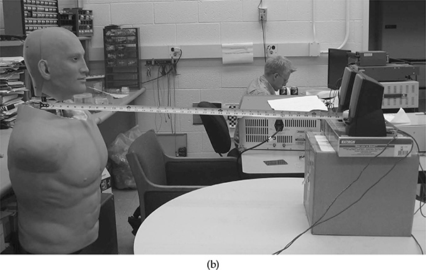
FIGURE 6.7
Typical acoustic testing of the robot system: (a) sound level experiment of the robot in an anechoic chamber, (b) audio recording experiment in a normal lab environment Typical acoustic testing of the robot system: (c) sound wave of the recorded audio, and (d) frequency spectrum analysis of the recorded sound data.
References
Albers, A., Brudniok, S., Ottnad, J., Sauter, C., and Sedchaicham, K. 2006. Upper body of a new humanoid robot: The design of ARMAR III. Paper read at the IEEE/RAS International Conference on Humanoid Robots, Genoa, Italy, December 4-6, 2006.
Behzadipour, S. and Khajepour, A. 2006. Cable-based robot manipulators with trans-lational degrees of freedom. In Industrial Robotics: Theory, Modeling and Control, edited by S. Cubero. Germany: ARS/plV.
Beira, R., Lopes, M., Praca, M., Santos-Victor, J. A., Bernardino, A., Metta, G., Beechi, F., and Saltaren, R. 2006. Design of the robot-cub (iCub) head. Paper read at the IEEE International Conference on Robotics and Automation, Orlando, FL, May 15-19, 2006.
Carbone, G., Lim, H., Takanishi, A., and Ceccarelli, M 2006 Stiffness analysis of biped humanoid robot WABIAN-RIV. Mechanism and Machine Theory, 41: 17-40.
Han, J. D., Zeng, S., Tham, K.Y., Badgero, M., and Weng, J. 2002. Dav: A humanoid robot platform for autonomous mental development Paper read at the IEEE International Conference on Development and Learning.
Hashimoto, T., Hitramatsu, S., Tsuji, T., and Kobayashi, H 2006 Development of the face robot SAYA for rich facial expressions. Paper read at the SICE-ICASE International Joint Conference. Busan, Korea, October 18-21, 2006.
Hirth, J., Schmitz, N., and Berns, K 2007 Emotional architecture for the humanoid robot head ROMAN Paper read at the IEEE International Conference on Robotics and Automation, Rome, Italy, April 10-14, 2007.
Hirukawa, H., Kanehiroa, F., Kanekoa, K., Kajita, S., Fujiwara, K., Kawai, Y., Tomita, F., Hirai, S., Tanie, K., Isozumi, T., Akachi, K., Kawasaki, T., Ota, S., Yokoyama, K., Handa, H., Fukase, Y., Maeda, J., Nakamua, Y., Tachi, S., and Inoue, H. 2004. Humanoid robotics platforms developed in HRP Robotics and Autonomous Systems, 48: 165-175
Miwa, H Okuchi, T., Takanobu, H., and Takanishi, A 2002 Development of a new human-like head robot WE-4 Paper read at the IEEE/RSJ International Conference on Intelligent Robots and Systems, Lausanne, Switzerland, September 30-October 4, 2002.
Nori, F., Janone, L., Sandini, G., and Metta, G 2007 Accurate control of a human-like tendon-driven neck. Paper read at the IEEE/RAS International Conference on Humanoid Robots, Pittsburg, PA, November 29-December 1, 2007
Park, I., Kim, J., Cho, B., and Oh J 2008 Control hardware integration of a biped humanoid robot with an android head Robotics and Autonomous Systems, 56: 95-103
Sabater, J M, Garcia, N., Perez, C., Azorin, J M, Saltaren, R J, and Yime, E 2006 Design and analysis of a spherical humanoid neck using screw theory Paper read at the IEEE/RAS-EMBS International Conference on Biomedical Robotics and Biomechatronics, Pisa, Italy, February 20-22, 2006
Sterling, A C, Cobian, D G, Anderson, P A, and Heiderscheit, B C 2008 Annual frequency and magnitude of neck motion in healthy individuals. Spine, 33(17): 1882-1888
Timoshenko, S. 1936. Theory of Elastic Stability . New York: McGraw-Hill.
White, A. A. and Panjabi, M. M. 1990. Clinical Biomechanics of the Spine. Philadelphia: J B Lippincott