
You have been given a general introduction to 3D printing. Now it's time to dive into preparing a file to be used in 3D printing. We will cover using the Ruler/Protractor to measure objects and texturing the model.
We'll be covering the following topics in this chapter:
- Precision modeling in Blender
- Using the Ruler/Protractor tool
- UV unwrapping
- Texture painting
- External textures
With 3D printing, every object comes out of Blender into the real world. It must fit on the printing bed of a real 3D printer. It has real walls that must support the weight of the object; it's got real limits on how small or large the detail can be.
Nothing in the real world is perfect.
Note
One note on the instructions in this book. Sometimes several keys need to be pressed at the same time. These will be represented with a plus between them such as Shift + D. Press both keys at the same time.
Pressing several keys in sequence will be represented by the word "press" followed by the keys separated by spaces, such as press S Y 0 Enter. You would press the S key, then the Y key, then the 0 key, and finally the Enter key.
Some commands may use both, such as press Shift + D Enter. Here, you would press the Shift and the D key at the same time. Then you would press the Enter key.
- Open Blender or open a new file by navigating to File | New File in the upper-left corner of the Blender window.
- With the mouse over the 3D View, press Z to get into wireframe mode.
- Press Shift + D Enter to copy the default cube. Press S and use the mouse to scale up the cube. Do it quickly; don't worry about exact size. Select the original cube with the RMB (Right Mouse Button) and scale it quickly. Press A to deselect them.
- Press Shift + A and navigate to Mesh | UV Sphere. Select UV Sphere. Press Shift + D Enter. Press G and move the sphere quickly in a direction. Select the other sphere and move it quickly in the same direction. Press A.
- Press Shift + A. Navigate to Mesh | Monkey. Select Monkey. Press Shift + D Enter. Press R and rotate the monkey quickly. Select the other monkey and rotate it quickly. Press the Home key.
You notice that your cubes are not quite the same size. Your spheres did not end up in quite the same place and your monkeys did not rotate to quite the same angle. Unlike usual Blender 3D modeling where dimensions are precise, with 3D printing, there is always some variation in conditions that affect the 3D print. Different printers, different batches of plastic, different materials, and different temperatures all cause variations in the final print.
Allowing for these differences is called tolerance. It means that a measurement should be X but we'll accept it within a certain closeness of X. Some of the things that can create this tolerance were discussed in the Factors affecting precision section Chapter 1, Designing Objects for 3D Printing.
Note
Look at the header at the bottom of the 3D View. Note the 20 small boxes, arranged in groups of five. These boxes control the display of individual layers. The top 10 boxes control layers 1 to 10. The bottom 10 boxes control layers 11 to 20. Layer 11 is on the left and layer 20 is on the right. A dark grey box means that the level is visible. A light grey box means that the level is not visible. A grey dot indicates that there are objects in that level. An orange dot indicates that an active object is in that level. Pressing the Shift key while making a selection allows multiple levels to be selected.
For any questions about Blender's controls, the Blender 3D Basics book has an excellent introduction to the Blender user interface; check out Chapter 2, Getting Comfortable Using the 3D View, to learn how to set up and use basic controls such as the numpad, mouse, or keyboard on Mac, PC, and Linux. In this book, we will be giving instructions using the standard Blender controls.
When building objects, you have to keep their dimensions and the ability of the 3D printer to reproduce them in mind. One of the handiest tools is a new tool called the Ruler/Protractor. It gives you a lot of power for measuring items, but can also be a bit tricky. Its operation may improve as it becomes more mature.
To learn how to use the Ruler/Protractor tool, let's use it to check how well a sword fits into its scabbard:
- Load the file
4597OS_02_Sword.blendfrom the code bundle of this chapter. Press Z for wireframe display. Press the Shift button and select layer 11 to see the scabbard. At this point, the hilt is not important, so press Shift and select layer 2 to hide it. - Press 7 on the numpad to view the blade from the end. Look at the upper-left corner of the 3D View. If you are not in Ortho mode, then press 5 on the numpad. Zoom in so you can see the scabbard and the blade clearly. It looks pretty good. The scabbard and the blade don't interfere with each other, and there is a little room all around the blade.
- In the Object Tools subpanel of the 3D View tool shelf, click on the Ruler/Protractor button. Move to the left edge of the blade and press Ctrl + LMB (Left Mouse Button). With the LMB pressed, move the cursor to the right edge of the blade. Then release the LMB. You will see a readout of the distance measured as seen in the following screenshot:
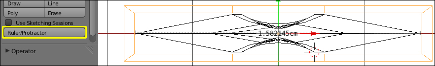
Don't worry if the readout that you see is not the same as in the screenshot. The Ruler/Protractor tool can be a little bit quirky, and we will discover how to get reliable measurements from it.
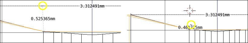
- Press 1 on the numpad. Look at the left-hand end of the ruler. Zoom out so you can see to the end of the blade. Obviously, the ruler, as seen in the left-side of the following screenshot, isn't just measuring across the blade.
- Select the left end of the ruler with the LMB and move it toward the top end of the blade. When you get it close, release the LMB and zoom in again. Pick up the end again with the LMB and move it close to the end of the blade. Press and hold the LMB and now press the Ctrl button and move the ruler end into place at the end of the blade. When you already have the LMB pressed, pressing the Ctrl button snaps the cursor to the nearest edge or vertex as seen on the right of the following screenshot.
- Repeat this with the right end of the ruler if needed.
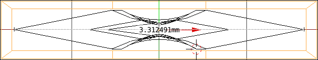
- Press 7 on the numpad to see the end view again. Adjust the ends of the ruler if needed. I measured just over 3.3 mm as seen in the following screenshot:
- Now, move the cursor to the top of the blade. Press Ctrl + LMB and move down to the bottom of the blade. Move the cursor a little below the blade and notice how the cursor jumps between the blade and the scabbard. The Ctrl button snaps the end of the ruler to the nearest edge or vertex.
- Press 1 on the numpad. Look at the new ruler carefully. Notice that the new ruler started at the same Z measurement that the first ruler was at. The last point has snapped to the corner of the blade. Rotate the view a little so you can see the first point separately from the first ruler. Select the first point and move it toward the end of the sword as seen on the right of the following screenshot. Press 7 on the numpad. Select the point again and start moving it. Then press Ctrl as you move it, and move it to the top of the blade. Then, after it snaps in place, press 7 and 1 on the numpad alternately to make sure it's in place. It's a little tricky, but now you can get an accurate measurement.
The ruler is not associated with any specific object. You can snap its measurement between two different objects. Now that you have some idea of how the ruler works, try it for measuring the gap between the blade of the sword and the scabbard.
- Now, check the vertical gap between the blade and the scabbard. Since you already have a measurement on the blade, start measuring from the scabbard.
You'll notice that the numerical readouts are not in mm or cm. These readings are in µm (micrometers or microns). I measured about 22 microns, or 0.022mm; that's tiny.
The specifications from one 3D printing service say that the accuracy for a detail-plastic copy of the sword would be ± 0.1 mm or 100 µm. Remember the last section, where you moved, rotated, and scaled the objects. The accuracy means that the measurement for the thickness of the sword could be 0.1 mm bigger than you intended, or it could be 0.1 mm smaller than you intended. The same holds true of the scabbard. You could get the sword turning out smaller and the scabbard turning out bigger; in this case, you'd have no problem. But if the sword turned out bigger and the scabbard turned out smaller, it wouldn't fit. This is called stacking tolerances, and must always be considered when making a multipart assembly. The following table lists possible outcomes of variations in the sword and scabbard:
|
SWORD | ||||
|---|---|---|---|---|
|
SCABBARD |
Bigger |
Correct |
Smaller | |
|
Bigger |
??? |
Okay |
Okay | |
|
Correct |
Bad |
Okay |
Okay | |
|
Smaller |
Bad |
Bad |
??? | |
Do you think that the scabbard should be enlarged? Remember that the clearance between the sword and scabbard is about 1/5 of the minimum accuracy that the printing service might guarantee.
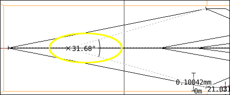
The Ruler/Protractor tool measures angles as well as lengths. Let's see how to do that:
- Move the cursor to the middle of the ruler that you used to measure the distance from the top of the blade to the bottom of the blade.
- Click the LMB and move the cursor toward the edge of the blade. The ruler becomes a protractor as seen in the following screenshot. It tells you the angle in degrees:
The Ruler/Protractor tool has one more trick. It will measure the thickness of an object:
- Press the Enter key to get out of the Ruler/Protractor mode and save your rulers. Go to the Visible Layers display on the 3D View header. Press Shift and click on layer 2 to display the hilt of the sword. Zoom out so you can see the hilt well.
- In the Object Tools subpanel of the 3D View tool shelf, click on the Ruler/Protractor button. Then choose an end of one of the rulers you have made. As you move it, press the Shift key and watch it automatically measuring the thickness of the object. Press the Esc key when you are done.
Remember that you can save these rulers and protractors or dispose of them. I have told you about deleting individual rulers. To get rid of all of them, just press Esc and the Ruler/Protractor mode will turn off and not save any of your tools. Press Enter and the rulers and protractors will be saved and Blender will exit Ruler/Protractor mode.