
There are other problems your model may have, which can also prevent it from being able to be printed by a 3D printer. They are as follows:
- Degenerate geometry: With faces that have no area and edges that have no length, these can often be fixed with the Remove Doubles command
- Distorted geometry: It has faces that are not flat
- Improper thickness: It has walls that are too thin
- Too sharp: It has edges that are too sharp, and will not print correctly, or the object may break during or after printing because it is too thin and fragile
- Too much overhang: It has polygons that do not have proper support and may sag, or break during printing on some printers
We will explore ways to fix these in this chapter and the next.
A distorted polygon is one that is not flat. A 3D printer may or may not have a problem with this. Following are the three things you can do with a distorted polygon:
- Flatten it
- Turn it into triangles because triangles are always flat
- Leave it alone and hope
When you export a Blender object to an STL file, the object gets triangulated automatically, so the distorted polygons are fixed, but the computer may not fix it the way you prefer. When you export a Blender object to an X3D file to make a textured object, the object is not triangulated.
Now, we'll examine the dragon for distorted polygons and see some of the things that we can do to fix them as follows:
- Turn off the normals display in the Mesh Display subpanel of the 3D View window Properties panel so you can see the dragon better.
- Click on the Distorted button in the Checks: section of the Print3D panel.
- Select the Non-Flat Faces: button in the Output: section of the Print3D panel. Note that it shows 14 nonflat polygons.
- Select the highlighted polygon on the dragon's arm as seen in the following screenshot:
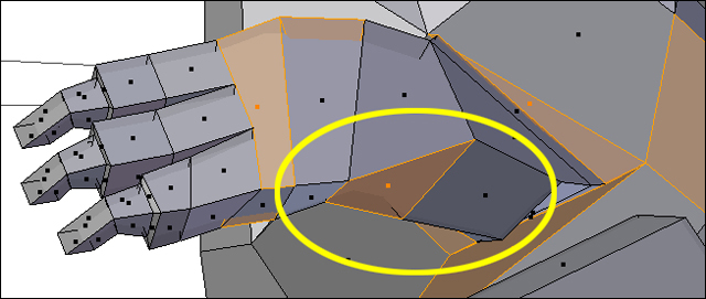
- Navigate to the Transform Orientation button in the 3D View header. Change it from Local or Global to Normal. Notice how the 3D Manipulator icon over the chosen polygon rotates when you switch to normal. When it is set to Normal, you can see that the Z axis points directly away from the surface of the polygon. The Z axis is now the same as the normal and indicates a ray pointing perpendicular to the surface of the polygon. Now any changes you make in the polygon will be done with respect to the polygon's normal.
- To flatten the polygon, press S Z Z 0 Enter. The letter S is for scale. Pressing Z twice tells Blender that you are not scaling in the global Z axis but in the local Z axis, and 0 says to scale it to zero. Enter executes the command.
- Click on the Distorted button again. Note that the Non-Flat Faces button now shows only 13 distorted faces. When you click on it, that polygon is no longer highlighted.
- Rotate the view so you can see under the dragon. There is a polygon at the bottom of the dragon's arm, highlighted as shown in the following screenshot. Fix it in the same way you just fixed the first polygon:

- Click on the Distorted button again. Note that the Non-Flat Faces button now shows only 12 distorted faces. The polygon that you flattened is no longer highlighted.
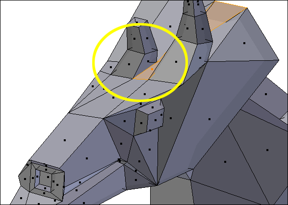
- Now, rotate your view of the dragon so that you can see the head. There is a distorted polygon in between the horns, as seen in the following screenshot:
- Get into vertex select mode. Choose the rear vertex at the base of the horn. Press 1 from the numpad to get the front view in the 3D View window.
- In the Preferences panel of the 3D View, scroll down and check the Mesh Analysis checkbox. Set Type: to Distortion and the range from 45 to 90 degrees.
- Distortion means that the polygon is not flat. The bending is measured in degrees. Below the lower value, the polygon is just displayed as a grey polygon. The lower number refers to the minimum distortion that the Mesh Analysis panel will display as distortion. The higher number refers to the maximum level of distortion that will be displayed. Any distortion greater than or equal to this number will also be displayed as red. This lets you set the upper and lower limits to search for a particular extent of distortion. In this case, I have allowed distortion below 45 degrees, and am tracking up to 90 degrees of distortion.
- Move the vertex down and to the left as seen in the following screenshot. Use the color changes provided by the Mesh Analysis panel as your guide. You can move it to where the distortion is less than 45 degrees:
- Uncheck the checkbox in the Mesh Analysis display subpanel.
- Click on the Distorted button in the 3D View toolbox again. Note that the Non-Flat Faces: button now shows only ten distorted faces. When you click on it, that polygon is no longer highlighted.
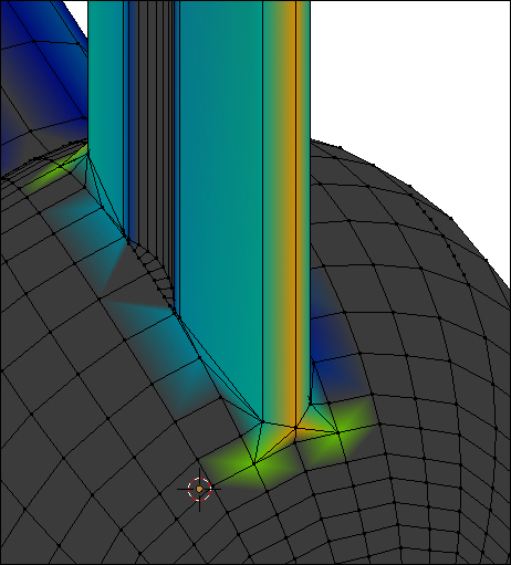
- Rotate the dragon so that you can see its side as shown in the following screenshot:
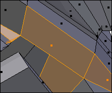
- Select the largest highlighted polygon seen in the preceding screenshot. Scroll up in the 3D View toolbox and select Deform: Smooth Vertex in the Mesh Tools subpanel.
- Click on the Distorted button in the Print3D toolbox again. Note that the Non-Flat Faces: button now shows only seven distorted faces. When you click on it, that polygon is no longer highlighted.
- Save your file to a unique name.
We've used several methods to smooth out distorted faces. These include scaling to zero along the normal of the face, moving individual vertices with the Mesh Analysis tool to guide us, and using the Smooth Vertex tool. There is no best method as sometimes smoothing one face will distort the surrounding ones more. And, as you saw in the last exercise, smoothing one may also smooth the ones surrounding it.
The Print3D toolkit does have one cure-all for distorted faces, pressing the Distorted button in the Cleanup: section will triangulate all the faces of the object and eliminate any distortion. However, our dragon uses the Subsurface modifier. The vertices we are working with now are the control vertices for the final surface. So, we won't triangulate the faces just now.
Sharp edges are pretty obvious. You know them when you see them. Sometimes they are okay to print, sometimes they are not. The problem is that the thinness of the material at the edge may allow the part to break in printing, shipping, or use. So, how sharp is acceptable depends on what material you select and how thick your material is. Stainless steel holds a better edge than sandstone. Some plastics hold finer detail than stainless steel.
There are two kinds of sharp features on an object, long thin edges and points. Let's examine an object that has both of these and complements our dragon well, a sword:
- Press the Tab key to get into Object mode. Select the fifth layer. Press Home to zoom in.
- Select the sword. Press the Tab key to get into Edit mode. The vertices of the hilt are all hidden to make working on the blade easier. Make sure that the limit selection to visible setting is off and its button is light grey.
- Press Ctrl + 7 on the numpad to see the blade from the bottom and zoom in so that the blade fills the window.
- Scroll down to the Mesh Analysis subpanel in the 3D View window Properties panel. Check the Mesh Analysis checkbox. Select the Type: button to Sharp. Set the lower limit to 20 degrees and the upper limit to 90 degrees.
Note
The lower limit of the Mesh Analysis button's Sharp Type: tracks the minimum angle that you are declaring to be a sharp edge. The upper limit is the largest angle you want to track. The difference between distortion and sharpness is that distortion is an angle of folding within a polygon. Sharpness is folding between two polygons. One thing that may be counter intuitive is that a 20 degree angle is a sharper angle than a 90 degree angle. But remember that a 180 degree angle is a straight line. 90 degrees is a right angle.
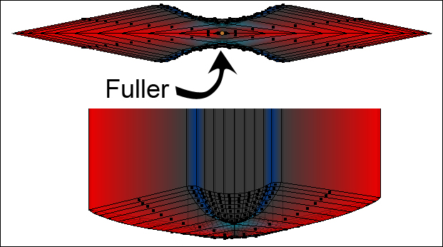
As you have probably guessed, the tip of the blade and the edges are the sharpest parts. They appear red as in the top of the following screenshot. So, the angle is about 20 degrees at the edges. Rotate the view a little so you can see the tip of the blade and the edges.
The edges of the fuller, which is the depression in the center of the blade, are blue because there is a greater angle between them and the fuller, in contrast to the gentle angles within the fuller which show up in grey as seen at the bottom of the following screenshot:
- Press Ctrl + 7 on the numpad again to see the base end of the blade. Use the Ruler/Protractor tool to measure the thickness of the blade from top to bottom, on either side of the fuller.
The thickness is about 0.44 mm. According to the specs for printing in nylon, the minimum thickness is 0.7 mm. So, this blade is going to need to be thicker. And it would be good if it was less sharp so that the edge of the blade is stronger. But, we still want a bit of a sharp edge just for looks. What we need to do is to make the fuller wide enough so that the blade will be strong. We will make it 0.9 mm thick. Then, we need to make the edge of the blade thick enough to be relatively strong, and add a point to the edge so it at least looks sharp.
- Press Esc to get out of the Ruler/Protractor tool. Press the Tab key to go into object mode, press A to deselect the blade. Press Shift + S and select Cursor to Center.
- Now press Shift + A and make a cube. Make the cube 0.9 mm x 0.9 mm x 0.9 mm in size. This is just a little larger than the minimum thickness. You can type in the values in the Transform subpanel of the 3D View window Properties panel. Then, select the blade again and go back into Edit mode. You can see the cube as a size reference for the blade.
- Go into Edge Select mode and press the Alt key while selecting the edge of the blade. You want to select the entire edge where the blade is the sharpest.
- Press V, and then Enter to rip the central edge into two separate edges.
- Switch to Face Select mode. Press B and use the border select to select all the edges of the upper half of the blade. There are a couple of small polygons right at the tip of the blade so be sure to get them. Zoom in after selecting to make sure that you have selected them.
- Press G Y and move the top half up so the top of the upper fuller is level with the top of the reference cube. You will see to two edges still connected from the top half. Don't worry about them.
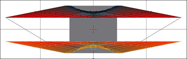
- Now select the faces of the bottom half and move them down until the bottom of the lower fuller is level with the bottom of the reference cube, as seen in the following screenshot:
- Next, select the two edges that go between the top half and the bottom half and delete them.
- Select the bottom edge of the upper half of the blade with Alt + RMB. Then select the top edge of the lower half of the blade with Shift + Alt + RMB.
- Choose Mesh on the View3D header then select Edges | Bridge Edge Loops from the pop-up menus.
- Select all the vertical edges you have just made by moving the cursor over one and pressing Ctrl + Alt + RMB.
- Press W and choose Subdivide from the pop-up menu.
- Press Shift + S and select Cursor to Center, and then set the pivot point to 3D Cursor.
- Select all the edges of the blade's new center edge with Alt + RMB.
- Press S X and move the edge out so the new sides of the edge are at about 45 degrees as seen in the following screenshot. If you scale it much wider, you will notice the edges of the sword turn red Press the LMB when done:
Now, as you can see in the preceding screenshot, some of the fuller is still not as wide as the reference cube that you made. This is okay. We made the reference cube a little larger than the minimum thickness for nylon. You can use the Ruler/Protractor tool and the width of the narrowest part of fuller should be just under 0.7 mm. It shouldn't be a problem because the fuller was invented specifically to make a real sword lighter without sacrificing strength. The material on either side of the fuller is thick enough, and we have taken the edge and made it thicker and blunter, so it should be strong enough as well.
Now we've made the blade wider but not the hilt. We should go and look at where they join and patch up any problems, as follows:
- Press 1 on the numpad, and then Home to display the entire length of the sword.
- Press Alt + H to show the hilt, or go to the 3D View header, select Mesh | Show/Hide | Show Hidden from the pop-up menus.
- Press Z to select solid shading. Turn limit selection to visible on. Uncheck the Mesh Analysis checkbox.
- Select an edge on the hilt next to the blade. Press . on the numpad to center on that edge.
- Rotate the sword so you can see the junction of the blade and the hilt.
- There are a few problems visible. The new edges you made for the blade are not attached to the hilt. The edges of the hilt are only attached to one side of the blade, so we need to go in and clean that up. It's not difficult.
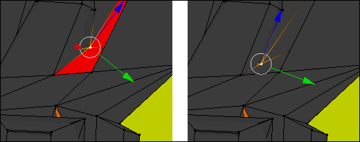
- Change to Face Select mode. Select the four faces as shown on the left side of the following screenshot. Delete them:
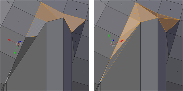
- Rebuild the junction of the blade and hilt similar to the faces on the right side of the preceding screenshot.
- Rotate the sword so you can see the other side of the blade. Repeat rebuilding the junction between the blade and the hilt.
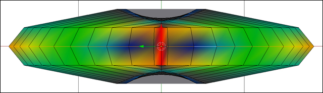
- Now switch on the Mesh Analysis button again. You can see, as shown in the following screenshot, that the sharpness is now confined to the new edge that you just built rather than the whole blade except the fuller:
- Use the Print3D subpanel to ensure that the sword is watertight and manifold. Save the file.