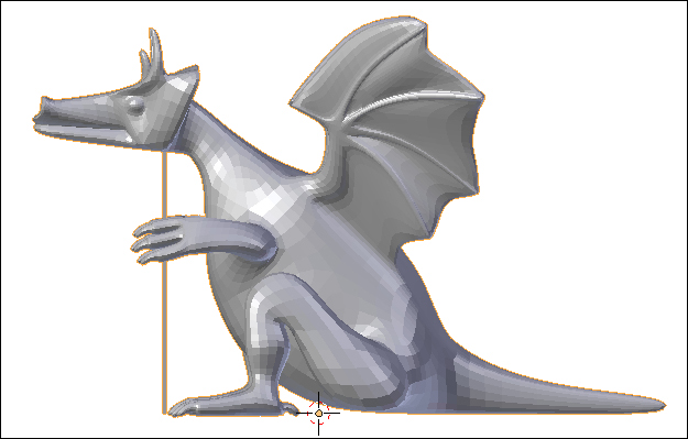
Your dragon is beautiful. Now it is time to make it useful and stick a pencil cup in its back:
- Press the Esc key to return to the 3D View in the largest window. Display only Layer 1.
- Select the dragon's inner shell. Go into Edit Mode. In the Mesh Display subpanel, click on the display face normals as lines button. A normal shows you which direction a polygon is facing. Make sure that all the normals are facing outward and that the blue lines used to represent them extend past the inner shell. If they are not, select all the edges and use the Recalculate button in the Tool Shelf. If the normals are not facing outward, the next step will not work right.
- Return to Object Mode. Open up the Boolean modifier subpanel. Booleans are very powerful modifiers. They allow you to control the shape of one object with another object. Here, we are going to use the Boolean modifier to put a complex depression into the back of the dragon. If you want an in-depth explanation of Boolean operations, check Chapter 8, Making the Sloop of Blender 3D Basics.
- For the Object, select Pen Cup Boolean Inner Shell. Choose Intersect as the Operation:. Click on the eye button so you can see the Boolean operation. It should look like the following screenshot:
- Go to Layer 12. Select the dragon's outer shell. Once again, make sure that the normals are facing outwards.
- Return to Object Mode. Open up the Boolean modifier subpanel. Choose Pen Cup Boolean Outer Shell as the Object. Choose Intersect as the Operation:. Click on the eye so you can see the Boolean operation.
- If they both look good, apply the Boolean modifier to the outer shell. Then go to Layer 1 and apply the Boolean to the inner shell.
- Press the Tab key to go to Edit Mode. In the Tool Shelf, select Normals: Flip Direction. This will be the inner section of the body, so the normals must point towards the inside instead of the outside as they usually do.
- Save the file so you have a version for a material extrusion printer.
If you are using a printer that uses a powder or liquid for material, you will need to cut holes out of the bottom so that the extra material can be removed. This is not necessary if you are using material extrusion printing like most hobbyist printers:
- Return to Object Mode. Press Ctrl + 7 on the numpad. Display layer 12. Select the outer shell. Set the Shading to Solid. Go to Edit Mode. Turn off the Normals: display. Display the faces.
- The printing specification allows us one hole, two holes, or four holes. They are thinking of round holes. In the interest of time, we will make rectangular ones. But remember that stress-wise, round holes are much stronger.
Note
To make round holes, what you do is create a cylinder of the diameter of the holes you want. Line it up where the hole should be; make sure it does not extend up into the pencil cup but does extend below the dragon. Duplicate it, move the duplicate across the x axis, and join the cylinders into a single object.
Select the outer shell, make a Boolean modifier, and choose the cylinders as the Boolean object. Use a difference operation, apply it, and then in the dragon, delete the vertices at the top of where the cylinder is inside the dragon. Repeat these steps with the inner shell, but delete the vertices at the bottom of where the cylinder meets the dragon. Then, you connect the holes in a similar manner to the way we connect the rectangular holes.
This is what I did for the sample dragon shown at the end of the chapter.
- For four holes, each hole should be 10 mm in diameter. Use the Ruler /Protractor to measure the width of the central polygons.
- It turns out that each polygon is about 5 mm on a side. So, to be roughly equal to four 10 mm holes, we need to delete 16 polygons as seen in the following screenshot:
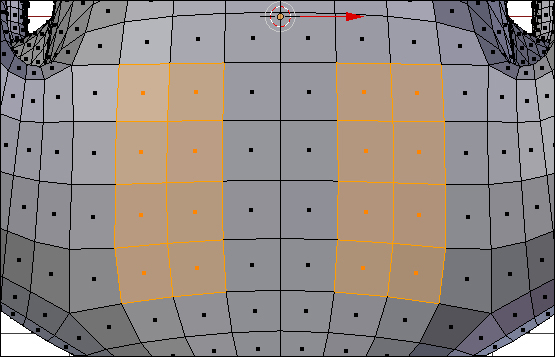
- Select the faces and delete them.
- Return to Object Mode. Display both Layer 1 and Layer 12. Select the inner shell and go to Edit Mode.
- Delete the faces in the inner shell that correspond to the holes in the outer shell.
- Go to Object Mode, press Shift, and select the outer shell as well as the inner shell.
- Press Ctrl + J to join them. Then press Tab to return to Edit Mode.
- Choose Select Edges. Press Alt + RMB and choose the edges that surround one hole of the inner shell. Press Shift + Alt + RMB and select the edges that surround that hole of the outer shell as well.
- From the 3D View header, choose Mesh and then navigate to Edges | Bridge Edge Loops from the pop-up menus. Repeat this with the other hole.
- Check that the object is solid and manifold. Save your file.
- Get into Object Mode. Turn on layers 12 and 20 to display your dragon and make the camera and lamp active. Do a test render to ensure that all your maps are in place.
Congratulations! Your dragon is done.
As a bonus, a tower shaped pencil/pen cup has been provided in layer 6. It can be any material you prefer. But before you go and print it up, you want to make sure it will fit into the dragons back. The clearance specification for the material that the dragon is made from is 0.9 mm as seen in the following screenshot. This means that there should be a gap of at least 0.9 mm between the dragon and the tower if you want to be sure that they won't bind:

- Get into wireframe mode. Use your measuring tools to check this. The easiest way in this case would be to just measure the outer width of the pencil cup at its bottom, and the inner width of the cavity in the dragon's back. Make sure that the width of the cavity is at least 1.8 mm (0.18 cm) larger than the width of the pencil cup. If they need to be modified, scale the pencil cup in X or Y as needed.
- You can scale it in X or Y, then note the scale in the 3D View Properties panel, and scale the pencil cup to the same percentage in the other dimension.
- Remember what you learned with the scaling of the dragon at the beginning of this chapter. Be sure to apply the scale to the object once it is the proper size. Other materials have different clearance specifications, and painting parts and other finishing techniques can also affect the clearance. Keep those factors in mind when sizing the tower. Save the file to a unique name.
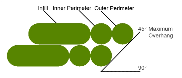
Material extrusion printers that extrude a filament of plastic have one additional issue that most other printers do not, the issue of overhang. Other printers use the raw printing material to support the object, but material extrusion printers cannot. When the printer is printing a layer without another layer directly underneath, there will be nothing to support the plastic that is being laid down. A 45 degree angle is considered the maximum angle that is acceptable. When the material extrusion printer deposits the perimeter of a layer, often the perimeter is two extrusions wide as seen in the following screenshot. The inner perimeter is supported by the layer underneath and the outer perimeter is supported by the inner perimeter:
There are four solutions to this problem:
- Modifying your object so there is less overhang
- Finding an orientation for your object where there is no overhang; printing it upside down or on its side
- The slicers for some material extrusion printers automatically make a support when they detect an overhang
- Making your own supports
If you are using a material extrusion printer that automatically generates supports, here's how to finish your object:
- Open the file you saved for a material extrusion printer. Go into Object Mode.
- Select the inner shell then select the outer shell. Press Ctrl + J to join them.
- Save the file to a unique name. You are ready to print.
If you have no other choice, then you must make supports for your model. This is not an exact science and you need to know what the printer you are using can do to span a gap between supports. Your dragon does not need holes in its bottom to shake out extra powder if you are using a material extrusion printer. Nor do material extrusion printers support textures; everything will be the same color:
- Open the file you saved for a material extrusion printer. Go into Object Mode. Select the outer shell.
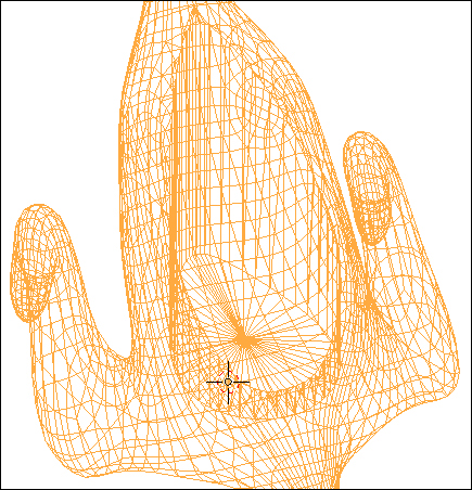
- Change to Solid View. Go into Edit Mode. Deselect all of the edges. Turn off the Normals: display. Rotate the view so you can see the bottom of the dragon. Check the Mesh Analysis checkbox in the 3D View properties panel. Set the Type: to Overhang. Set limit the selection to
visible. The dragon will look similar to the following screenshot: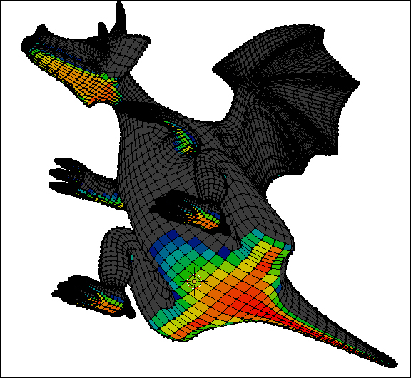
If you were making a support for the dragon, the Mesh Analysis would look like the preceding screenshot. The colored areas have all been flagged for needing support. The tail, bottom, and feet will all be on the printer bed, so they don't need to be supported. The belly, paws, and head do need support:
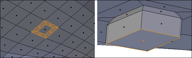
- To build a support, first go into Face Select mode. Select a polygon that has been colored red by the Mesh Analysis, say under the dragon's chin. Press I to inset the face and then scale it down to about the smallest size you think the printer can print, as seen on the left-hand side of the following screenshot. This is to make the support easy to break off after you have printed it and minimize the sanding you will need to do.
- Select the polygon in the center of the inset. Extrude it a little.
- Set the pivot point to Median Point. Scale up the face to a size that you think can support the weight.
- Extrude it again as seen on the right-hand side of the following screenshot. Press Shift + S and choose Cursor to Center. Set the pivot point to 3D Cursor. Press S Z 0 Enter to make your support flat on the bottom and extend down to the printing bed.
- Now you have a support that goes all the way to the printing bed, as seen in the following screenshot. Make as many as you need to hold up the unsupported part of the object.
- Go into Object Mode. Select Layer 1 as well as Layer 12. Select the inner shell as well as the outer shell. Press Ctrl + J to join them.
- Save your file.