
The first difference to realize between making colors in Blender for 3D printing and the usual way of making colors in Blender is that you have less control. All you can control is the diffuse color. You cannot make the object shinier by adjusting the specularity, you cannot add transparency, or any of the other controls. In this respect, a 3D printer is like a regular printer. All it understands is a colored pixel. If you use transparency, at best it will show you the bare physical material underneath. Shininess, specularity, and so on are all properties of the material that you are printing with.
There are three ways to color your model:
- Leave the model uncolored and select a colored material when printing
- Assign colors to the polygons
- Assign a texture map to the polygons
Many 3D printers do not handle color. This includes printers that print metal, extruded plastic, or liquid resins. The final color of the object comes from the material selected. Many colors and materials are available. You can dye or paint the objects after they are printed. The lunar lander in Chapter 1, Designing Objects for 3D Printing, was printed in this way. It was printed in white nylon then dyed yellow and grey. Next, the joystick was painted red and black with acrylic paint and a small image of the lander's touchscreen from a standard color copier was glued into place. Blender exports an STL file for printers like these.
Assigning color to the polygons is the easiest way, but it's also the most limited because your minimum detail is constrained by the size of the polygon. When you select a polygon and assign a color to it, the color is assigned to all vertices of the polygon:
- Open Blender or press Ctrl + N for a new file. With the default cube selected, press the Tab key to go into edit mode.
- In the Properties panel header on the right, select the shiny ball. This opens the Materials panel.
- In the Diffuse subpanel, set the color to
red. - Click on Assign. The first material assigned to an object is assigned to all polygons by default.
- Click on the plus sign to the right of your red material. Click on the New button. Set the Diffuse color to
yellow. - Press A to deselect all of the vertices. Press C and then move the mouse over four vertices in a polygon while pressing the LMB. Press the RMB when you are done and click on the Assign button.
- Press F12 to render the scene and view it. Then return to the 3D View window by pressing Esc.
That's pretty simple, and when it is printed, you will have a red cube with one yellow side.
Blender has painting tools included to do vertex painting, which is much easier than just selecting faces and assigning them colors and produces a better result. Vertex painting allows you to set the colors vertex-by-vertex. Then, the computer blends the color between the vertices. So, between a blue vertex and a white vertex, the edge and part of the face will go from blue to light blue to white. Let's see how vertex painting works:
- Press Tab to go from Edit Mode to Object Mode. Press A to deselect the cube. Press Shift + A and navigate to Mesh | UVSphere from the menu. Select UV Sphere. Press G and use the mouse to move the sphere to the right of the cube. Press the LMB to stop moving the sphere. Zoom in so you can see the sphere better.
- Press V to go into vertex paint mode. The sphere turns white, and in the toolbox on the left of the 3D View, there is a color palette and paint brush controls. Choose a color and set the radius of the paint brush to
15. Put the cursor over the sphere. Press the LMB and move the mouse to paint some of the sphere. - Change the color and paint more of the sphere. Choose a third color and just press the LMB to do small dabs of paint. Notice how it only paints at the vertices, not everywhere.
- Go to the Properties panel. Make a new material. Scroll down to the Options subpanel and check Vertex Color Paint. Press F12 to render.
Pretty easy! You can see how the colors are centered at the vertices and blended between them. Feel free to play a little more with coloring and rendering.
The most powerful way of adding a texture to your object is by using a texture map. Do not use a texture map and vertex colors on the same object, especially if the two methods share a vertex. The 3D printer may not choose the right material.
Tip
Make sure you delete any unwanted materials before exporting your object for 3D printing. This is easy. With your object selected, just select the materials button on the Properties window header. It's the one that looks like a chrome ball. At the top will be a list of the materials assigned to the active object. If you click on them, the Preview window will display a preview of that material. To delete the material, simply click on the minus button to the right of the list of materials.
Texture mapping gives you the best control over the color of any part of the surface. It also gives you controls so you can assign the locations of different regions of the texture and use another program such as Gimp or Photoshop to create fine details.
The most common colored 3D printing material is gypsum, sometimes called sandstone. The following graphic is a chart of colors used in printing full color sandstone:
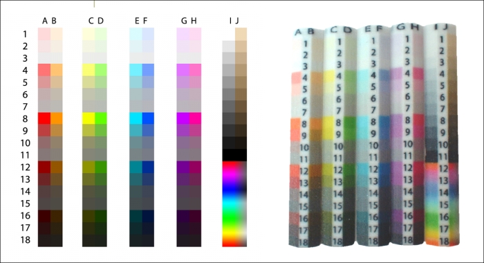
You get them from the printing service. The chart on the left-hand side of the preceding diagram shows you a range of colors. The bars on the right-hand side are 3D-printed samples printed with the same colors. Look at the printed samples to choose the printed color you want. Read the index number off of the samples. Then, use a program such as Gimp or Photoshop to get the exact RGB values of the indexed color which you can use to specify the exact color in Blender.
This is a useful tool because the colors printed are not always exactly as you specify them. You can see this if you look at one color in the previous chart and samples. And indeed, the printing service specifies that no two samples may be exactly the same. So it's a rough guide, not an exact one. A copy of the chart on the left-hand side is in your download kit as 4597OS_02_01.png.
UV mapping is a way of assigning a section of a graphic image to the face of a polygon. This is done by a process called unwrapping the UV mapping. The letters U and V describe the horizontal and vertical axes of a bitmap image. The letters U and V are used to avoid confusion with the X, Y, and Z geometry coordinates.
Creating UV maps may seem intimidating, but it's not that difficult. To unwrap the UV mapping, you select a polygon and press the UV Unwrap button. Then, Blender assigns a pair of UV coordinates to each vertex of the polygon and gives them an initial value. Next, in the UV/Image editor window, an image is displayed with an overlay that shows where the UV coordinates for the polygon are with respect to the image. You then move these coordinates around until they are over the section of the image that you want to be displayed on the face of that polygon.
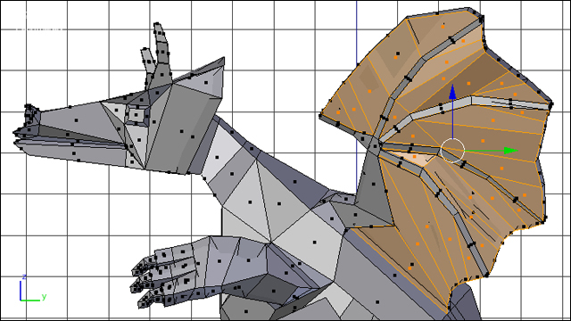
Next, you will do some texture mapping onto a model of a dragon that we will be working on for most of the rest of the book. We will decorate its wings, its chest, and its head.
We will start by applying UV maps to the wings. This will give us good practice in moving the UV coordinates as groups:
- Open
4597OS_02_Dragon_Untextured.blendfrom the code bundle. - In the Properties panel, turn the visibility controls for the Mirror and Subsurf modifiers off; they look like eyes. Half of the dragon will disappear and it will look very blocky. The Mirror and Subsurf modifiers will be used in Chapter 3, Making a Blender Model that's Ready to Print, and Chapter 4, Making Strong, Light Objects with the Solidify Modifier, but they are not needed now.
- Press Tab to get into Edit Mode. Press 3 on the numpad to get a side view. Click on the Face Select button.
- The lower-left window is the UV/Image Editor. Select Image from the header and then choose New Image from the popup menu.
- For the dragon's general color, I chose the color square D12 from the chart in the preceding image. Its value is 0.224 Red, 0.58 Green, and 0 Blue. Use those values for the background color of the image. The size should be 1024 x 1024. Then, click on OK. Press Home to see the entire image.
- In the 3D View, pan down and zoom in so you can see all of the leading edge of the wing as shown in the next screenshot. Press C and select the faces of the front of the wing as seen in the next screenshot. Do not select the faces of the very edge of the wing, just these 5 faces on the side of the wing. Press the RMB to stop selecting.
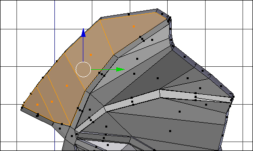
- This is the membrane of the wing. The narrow sections on either side of the membrane are the dragon's fingers. Select the rest of the membrane areas, as seen in the following screenshot:
- Select Mesh from the 3D View header. Then, navigate to UV Unwrap | Unwrap from the pop-up menus. Select Unwrap. In the UV/Image Editor, your green image disappears and is replaced by the UV coordinates of the polygons that you have just unwrapped, as seen in the following screenshot:
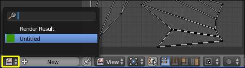
- To get your image back, select the Browse Image to be linked button which is to the left-hand side of the New button, as seen in the previous screenshot, and select your green Untitled image from the pop-up menu. Press Home to see the whole image.
- In the Properties panel, select the Object Data button that looks like a triangle. In the Vertex Groups subpanel, click on the plus button and create a new vertex group. Name it
Texture - Outer Wing. Assign the faces to it. This assigns all the faces that are currently selected in the 3D View to the vertex group.
Using Vertex Groups to organize your sections of texture is very important. It means you will never have to go through selecting the faces again. This gives you a lot of flexibility if you make a mistake and greater control when working with the UV maps.
The first thing that you notice when you look at the UV/Image Editor is that the mapping of the UV coordinates does not resemble the shape of the wing. You want to reorganize the UV coordinates so that they do:
- Find the section that resembles the first membrane that you selected. Select one UV coordinate on it with the RMB. Press L and the whole membrane section is selected, as seen on the left-hand side of the following screenshot:
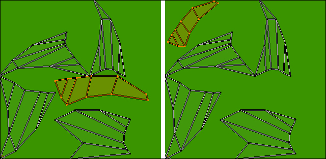
- Now, rotate this group of UV coordinates into the same orientation that the faces are in the 3D View window. Press R and rotate the coordinates so they are at the same angle as in the 3D View. Press S and scale them so they cover a little less than a quarter of the height of the green image. Press G to move them to the top-left corner of the image as seen in the right-hand side of the preceding screenshot.
- Select the next section of membrane in the same way as you selected the first. It's the upper-left one that you have not modified, as seen on the left-hand side of the following screenshot:
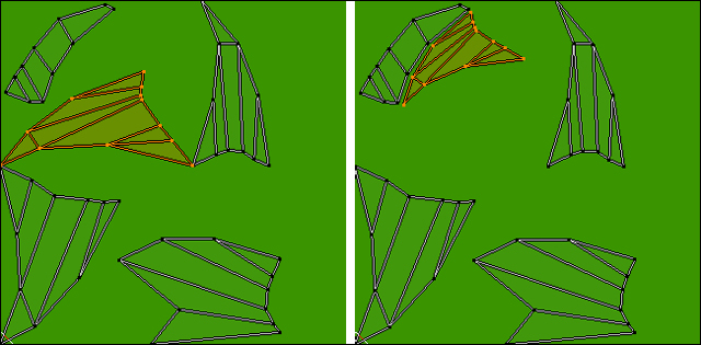
- Rotate, scale, and move it so it is snug with the first membrane section as seen on the right-hand side of the preceding screenshot. Leave a gap between them where the fingers of the wing should be.
- Next, repeat this with the third membrane. It's the one in the lower-left corner. There is a trick with this one. If you look carefully, you'll see it's backwards in X. So, first press S X -1 Enter. This will flip the UV coordinates along the x axis. Then rotate, scale, and move it into place next to the other two membranes.
- Now move, rotate, and scale the fourth membrane into place.
- Repeat this with the membrane between a finger and the dragon's body. Now it looks like a wing, as seen on the left-hand side of the following screenshot:
Good. Since the UV coordinates are now laid over the image in a shape like the faces of the wing, when you paint the wing, you will know which part of your image is mapped to which part of the wing. Now, to help us remember which section of the image has already been used, let's outline it:
- There are two buttons labeled View in the UV/Image Editor header. Choose the one in the center of the header with the icon of an image. Select Paint from the pop-up menu.
- Press N to get the UV/Image Editor properties panel. Scroll down to the Paint subpanel. Set the color to red. Set the radius of the brush to
5. - Use the Ctrl + MMB (Middle Mouse Button) to zoom into the part of the image where you see the UV faces and Shift + MMB to pan. Outline the faces as done in the preceding screenshot. You are just marking the area where the UV coordinates of the outer wing are so you will know what areas of the image are still available to put the other UV coordinates that you create.
- Click on the button labeled Paint and choose View from the pop-up menu.
Congratulations, you have texture mapped the outer side of the wing. Now it's time to do the inner side:
- Move the cursor over the 3D View window. Press Ctrl + 3 on the numpad to see the other side of the dragon. In the Vertex Groups subpanel of the Properties panel, click on the plus button and create a vertex group named
Texture - Inner Wing. - Press A to deselect all the faces. Press C and select the faces of the inner side of the wing membrane.
- Assign these vertices to the
Texture - Inner Winggroup. Now, UV unwrap the inner side of the wing membranes just as you did for the outer side. Use theUV Unwrapcommand, display your Untitled image, and move the UV coordinates. Be sure to start building your mapping from the upper-right corner of the image at about the same size as the outer wing was mapped. Do each section as before. - If you get stuck and you can't figure out which of the membranes is which, make sure you have assigned the vertices to the
Texture - Inner Winggroup. Then, in the 3D View, press A to deselect all faces and then select a face from the membrane whose UV coordinates you want to move. They will appear in the UV/Image Editor and you can note where they are. Then, go to the Vertex Groups subpanel and click on Select to have all the faces of the inner wing appear. - Once all of the membranes are in place relative to each other, press A in the UV/Image Editor to select all of them then scale the whole so it is about as large as the outer wing as seen in the following screenshot:
- Paint an outline around the inner wing to mark where it is.
- Save your Blender file. Then, go down to the UV/Image editor header. There is an * next to the word Image. This means that the image in the UV/Image editor has been changed since it was last saved. Click on Image then choose Save As Image from the pop-up menu. Save it in the same folder as your Blender file. You never know what kind of folder structure the printer is using, so it's best to keep them together.
Now we map the dragon's belly. This will give us practice in modifying individual UV coordinates.
Now, it's time to texture the dragon's belly:
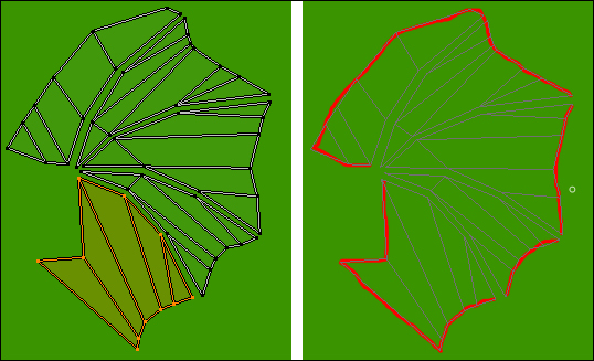
- Press A to deselect all the polygons. Press C and select the column of polygons from the dragons, chin down to his bottom as seen in the following screenshot. Don't select the polygons on his tail.
- Make a new vertex group named
Texture - Bellyand assign the vertices to it.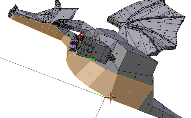
- Unwrap the UVs and display your image again.
- Move the cursor over the top row of edges in the UV/Image Editor. Press Alt + RMB to select the top row of edges. Press S Y 0 Enter. This will put all of the selected UV coordinates at the same height.
- Repeat these steps for the bottom edges. The edges will now be parallel.
- Now, move the UV coordinates of the bottom row one-by-one so that the vertical edges are straight up and down. After selecting a UV coordinate, pressing G X before you move it will limit your motion to the X direction and make control much easier.
- Select all of the UV coordinates. Move them almost to the bottom as seen in the following screenshot. Leave a little room below them though.
- Go into Paint mode and outline where the top row of UV coordinates are. Return to View mode from Paint mode.
- The reason for making the top and bottom rows parallel is that now if you make scales all of the same size in your art, they will appear smaller when they are at the neck than at the bottom of the dragon's belly.
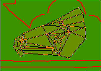
Mapping the edges of the wings is very similar to mapping the belly and the wings. First you work with groups of UV coordinates, then you work with individual UV coordinates:
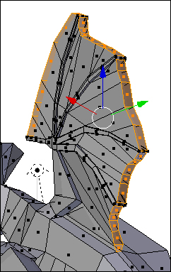
- In the 3D View window, press A to deselect all polygons. Rotate your view so you can see the edge of the dragon's wing. Select the edge of the membranes as seen in the following screenshot. Do not select the edge of the fingers:
- In the Properties panel, make a
Texture - Edge Wingvertex group. Assign the faces to it. - UV unwrap them. What a mess. What we want to do is line all of the UV coordinates into two nice rows. Remember about deselecting all of them and choosing some faces in the 3D View as a way to get your bearings? Start at the front of the wing and work your way to the back.
- Move the faces of the edge so that they are in an approximate line. With the mouse over the UV/Image editor, press A to deselect all the UV coordinates. Press Shift + Alt + RMB to select the entire top row section-by-section as seen in the following screenshot:
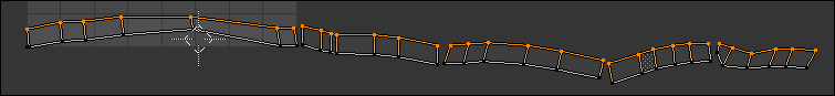
- Press S Y 0 Enter. Then, press G Y and move the top row up a little so that the two rows do not overlap.
- Select the bottom row only. Press S Y 0 Enter. Press G Y and move that row up so it is about as thick as the UV coordinates were originally.
- Select all of the UV coordinates. Get your image background displayed in the UV/Image Editor.
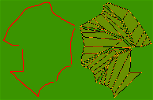
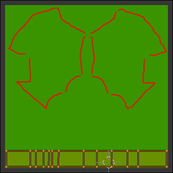
- Scale the UV coordinates so that they fit in the image area. Move them just above the area for the belly, as seen in the following screenshot. Paint a red line on the graphic at the top of the area they occupy to mark where they are.
Note
Note the solitary orange dot near the lower-left corner of the following screenshot. This is a quirk of Blender. You selected only the faces of the edge of the membranes. But, since the faces on the end of the fingers shared vertices with the edges of the membranes, Blender also picked them up. Since you did not choose them, it did not assign them any area on the UV map. It just lumped them all together in one spot. This will work; just make sure that they are all mapped to an area with the background green. Use the C or B command to select them if you want to move them.

With the UV coordinates of the head, we will learn to adjust the UV coordinates to emphasize certain details, giving us more of the texture map to use on these details and allowing us more creative control:
- Save your image file and your Blender file.
- With the cursor over the 3D View window, press A to deselect all faces. Now, select the polygons of the dragon's head. Do not select the area under the chin because you have already assigned that to the belly. Do not choose any polygons on the back of the frill or the neck. Rotate your view to be sure you get the nose, the corner of the mouth, and all sides of the horns.
- Make a vertex group,
Texture - Head, and assign the vertices to it. UV unwrap it and display the green texture map image. - Select all the UV coordinates in the UV/Image Editor. If the nose is at the bottom, you will need to scale the dragon's head; if you do, press S Y -1 Enter to get it into the proper orientation. Now, scale, rotate, and move the UV coordinates so that they fill the remaining available area in the texture map as seen in the following screenshot. Draw an outline around it:
- Save your files. You now have your dragon texture mapped.
- You may want to take some time to make adjustments to the mapping. Have the UV coordinate sets cover as much of the image area as possible. The greater the area that these sets cover, the more pixels are mapped to them. The more pixels that are mapped to a face, the more detailed the texture can be.
Note
You may have noticed that we have not texture mapped the entire dragon. In the following chapters, we will modifying some of the geometry to put a pen cup into his back. This will destroy the UV mapping of any faces that are involved. Only the faces on the center of the dragon's back are affected, not the wings. But Blender does provide a default UV mapping in this case. It takes the four corner pixels of the texture map and uses the average of these four pixels as the color for all unmapped polygons. So, make sure that none of your UV coordinate faces cover the four corner pixels of the image.
It's time to paint your texture. You have a choice of methods. You can continue to use the Paint tool in the UV/Image Editor, or you can export your UV maps as a .png file for use in another program such as Gimp, Photoshop, or whatever you prefer.
Exporting the UV Layout lets you have the power of the best graphics programs for making a texture map. When you export the UV Layout, it is in the form of a .png file that you can read into another graphics program. One layer will be an image of all of the UV coordinate locations. Make an image on other layers, using the coordinate layer to guide you. Turn the coordinate's layer off when you are done and save a bitmap copy of the finished graphic. Then, bring it back into Blender as a texture map for the object.
It's easy to export your UV map. Display all of the UV coordinates that you want to show up on the map and use the Export UV Layout function:
- To export your UV map, change from Paint to View.
- In the Vertex Group subpanel of the Properties panel, for each of the vertex groups, choose the UV map and then click on the Select button.
- Select UVs from the UV/Image Editor header. Choose Export UV Layout from the pop-up menu. Put this map into the same directory as your Blender file. Choose a name and then press the Export UV Layout button in the top-right of the page. This will create a
.pngfile with a layer that you can use as a guide to creating a texture map for your dragon.
You can also create a texture map using Blender's paint tools. This may be more convenient, even though you don't have quite as much control as you get in a dedicated graphics program such as Gimp or Photoshop.
Now you can paint the image in the UV/Image editor. You'll then save your file and create a material that employs the UV mapping work that you've done and mates it up to the texture map that you make:
- To use the Paint tool, return to Paint mode. Paint the wings of your dragon. Paint the outer wing, the inner wing, and the wing edge.
- Return to View mode. Save your image file to a new name. It's time to apply the texture.
- In the Properties panel, select the Materials button in the header; it's the one with the chrome ball on it. Click on the New button to make a new material.
- Now, click on the checkerboard button next to the Materials button. Click on the New button. Click on the Type: button where it says Clouds. Select Image or Movie from the pop-up menu.
- Scroll down to the Image subpanel. Select Open. Choose the
.pngfile you just saved. - Scroll down to the Mapping subpanel. Click on the Coordinates: button where it says Generated. Choose UV from the pop-up menu.
- Press F12. You will render the dragon with its wings painted. Save the file. Press Esc to close the rendered image.
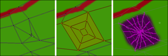
You can also modify the UV coordinates to use more of the texture map for more important details and use less of the texture map on less important details. Here, you add more detail to the horn on his head by adjusting the UV coordinates and painting on the texture map:
- In the UV/Image Editor, zoom into the inner horn as seen on the left-hand side of the following screenshot. It's kind of small. Get into View mode. Move the UV coordinates out to cover more of the texture map and organize them as seen in the center of the following screenshot.
- Next, go into Paint mode and paint it as seen on the right. You don't have to copy what I did though. Then, return to View mode and save the image to the same name as you did before.
- In the Image subpanel of the texture panel in the properties window, click on the button with the opposing arrows to reload the texture file. Press F12 to render the dragon.
Now, as a final touch, we will explore how to add better detail to the texture map by bringing in an outside graphic and duplicating the patterns from it.
- In the UV/Image Editor, pan down to the area reserved for the dragon's belly. Go into Paint mode. In the Paint subpanel of the UV/Image Editor properties panel, choose the F Clone brush. The brush selection is just below where it says Paint. Set the radius of the brush to about
25and the strength to1.0. - In the UV/Image Editor header, select Image. Select Open Image from the pop-up menu. Choose
4597OS_02_02.pngin theImagesdirectory. Press Home. - Select your texture map with your wings from the header again.
- In the Paint subpanel on the left-hand side of the UV Image properties panel, click on the picture button next to Image:. Select
4597OS_02_02.png. The image of the scales will appear at the bottom of the UV/Image Editor window. - In the UV/Image editor, zoom in to the area of the belly. Use the Clone brush over the belly area.
- When you have finished painting the clone area, return to View and save the image. In the Image subpanel of the Properties panel, refresh the texture as you did after painting the horn. Press F12 to render the dragon.
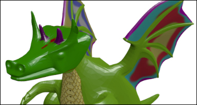
Now, something may look odd. The dragon's body is a different shade of green than its head is as seen in the following screenshot. Remember about the pixels in the corner that I mentioned in the last information box? You probably painted over two of the corner pixels when you used the Clone brush. But that is easy to fix:
- Return to Paint mode. Choose the F Brush. Click on the brush color button below the color wheel. Another color wheel pops up. Click on the eyedropper button on the popup color wheel. And click the eyedropper cursor over a green part of the image. Set the radius of the brush to
2and the strength to1.0. - Paint the bottom-left corner and right-corner pixels of the image green. Don't paint into the UV area of the belly. If UV coordinates extend to the corner, select them and move them up a few pixels. Retouch the scales with the F Clone brush if needed.
- Return to View mode. Save the image and the Blender file. Then refresh the texture as you did after painting the horn. Rerender it and it should be fine.
- Now you can paint the eye, and if you want, paint a little blood on its lips.