Solutions in this chapter:
Having discussed motors, sensors, geometry, and gearing, we’ll now put all these elements together and start building something more complex. LEGO robotics should involve your own creativity. You won’t find any rules or style guides in this chapter, simply because there aren’t any. What you will find are some tips meant to make your life easier if you want to design robust and modular robots.
Building with studless LEGO pieces is different from traditional studded building. Simply stacking pieces together to make strong robots and structures is not an option with studless building. As you build with studless pieces, you may notice that studless structures tend to be more flexible than similar studded structures. Don’t confuse flexible with weak. Properly built studless structures can be just as strong as those built with studded pieces. The two building systems are different, and they require different building techniques.
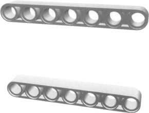
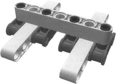
The main structural component of any robot built with studless pieces will be the studless beam. Let’s start with two white studless beams oriented as shown in Figure 6.1 There are many ways to connect these two beams, and all of them have advantages and disadvantages. Figure 6.2 shows four components that you can use to connect the two beams.
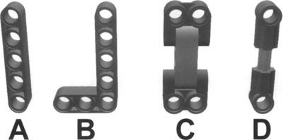
Option A is a simple beam that you can pin to each parallel beam. A single beam won’t be very useful, but as a pair, they will connect the two beams and keep them parallel to one another. This type of connection is called a parallel linkage. In it, the two white beams will always be parallel to each other, as will the two gray beams. This will work well in some situations, but most of the time you’ll want a more rigid assembly.
Note
Remember to use the black and blue pegs (or pins) when connecting beams. They fit in the holes with much more friction than the gray or tan ones, because they are meant for building rigid components and structures. The gray and tan pegs, on the other hand, were designed for building movable connections, such as levers and arms.
You can use option B to make a more rigid assembly. Replace one of the gray beams with the L-shaped piece. Be sure to use three pins to connect it to the white beams. You’ll discover that the assembly is both strong and fairly rigid.
You can use option C on its own, to connect the two white beams. It will keep them parallel to one another and not allow them to move. However, this option is less rigid than a combination of options A and B. Use option C to connect the two white beams. Now gently press the two white beams together with your thumb and forefinger. It doesn’t take much force to make them move a little bit. This connection might work in some cases, but if you start putting some weight (such as our NXT) on this, it might bend or come apart.
Option D is another method. You can use it much like you used the two beams in option A. This method has one major drawback. It will not work under tension. In other words, you can pull it apart easily. Option D will work only in compression when the two white beams are being forced together.
Now let’s change the orientation of the two white beams and try to connect them in a different way. Figure 6.3 shows several ways to connect beams in this new orientation. The first two options, A and B, use pieces designed specifically for this purpose. These two connectors will keep the two white beams together and parallel to each other in all directions. Both work very well in many situations. However, both fail when placed under tension. In other words, when the two white beams are pulled apart, the pieces easily separate.
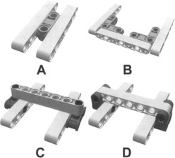
Options C and D are also good ways to connect the two beams. However, as constructed, both of them fail in compression, when the two white beams are pressed together. You can construct options C and D so that they will not fail in compression by placing the two white beams outside of the two black connectors.
So, what can you do to keep the assembly together in both tension and compression? Starting with option C or D, you can simply add two more connectors, as shown in Figure 6.4 This prevents failure in both tension and compression. This type of connection also has another major advantage. Unlike options C and D, where the two white beams can still move in one direction or another when connected, these two beams are fixed in position and cannot pivot, rotate, or slide. This results in a strong and rigid assembly that will not easily fall apart.
Despite our insistence on the importance of connecting beams for a strong and rigid assembly, there’s no need to go beyond the minimum required. Eliminating unnecessary parts can result in a smaller, more compact, and lighter weight assembly. Weight is, actually, a very important factor to keep under control, especially when dealing with mobile robots. The greater the weight, the lower the performance, due to the inertia caused by the mass and because of the resulting friction the main wheel axles must endure.
While building your robot, you will likely have to dismantle and rebuild it, or parts of it, at least, many times. This isn’t like following someone’s detailed instructions; it’s more of a trial-and-error process. Unless you’re a very experienced builder and are blessed with clear ideas, your design will develop in both your mind and your hands at the same time.
For this reason, it’s best to make your model as easy to take apart as possible, or, to term it more appropriately, your robot should be modular in construct. Building in a modular fashion also gives you the opportunity to reuse components in other projects, without having to rebuild common subsystems that already work. This is not always possible, because when you want something really compact, you have to trade some modularity in favor of tighter integration. Nevertheless, it’s a good general building practice, especially when constructing very large robots.
Building with the NXT motors and sensors requires a little more planning than building with legacy LEGO motors and sensors. Their unique shape and unique location of mounting points make them difficult to simply attach anywhere with little planning. For this reason, you’ll probably want to plan where they will be in the finished design and build them into the structure of your robot from the very beginning. Doing so will probably make your finished design more compact as well as stronger. Unfortunately, it will probably be nearly impossible to easily remove your motors without destroying a large part of the surrounding structure.
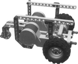
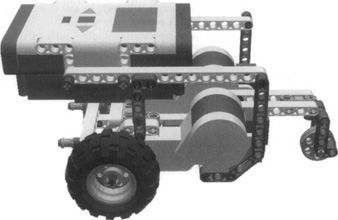
So, how can you maximize modularity while at the same time tightly integrate the NXT, motors, and sensors into a robot? By creating subassemblies that, when combined, make up the complete robot. A subassembly would have the motors, sensors, and/or NXT tightly integrated within it. Assembling the multiple subassemblies should be easy. This way, you can remove, rebuild or improve, and reinstall a single subassembly without altering the other subassemblies. The bucket robot in Figure 6.5 illustrates these ideas. You can break down this robot into three subassemblies.
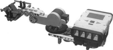
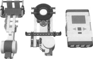
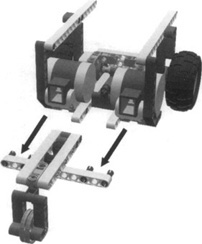
Remove the two pins on each side that connect the top motor to the turntable (see the arrows in Figure 6.5) and the wire connecting the motor to the NXT. This separates the bucket subassembly from the rest of the robot. The NXT is a subassembly of its own. You can remove it by simply pulling up on it. Figure 6.6 shows the three separate subassemblies. You can modify or change each one entirely without affecting the others as long as the mounting points where they connect to each other do not change.
Note
One good reason to make your NXT easily detachable is that you must be able to change batteries when necessary. The most common solution is to keep the NXT at the very top of your robot—this way, you can also easily access the push buttons and read the display. It is also a good idea to have easy access to the sensor and motor ports, as well as the USB port on the NXT while it is installed in your robot. That way, you can attach motor and sensor cables as well as the USB cable, all without having to remove the NXT from your robot.
Modular building has another advantage. At some point, you may build a very large LEGO robotic creation and wish to share it with friends at school, a local club meeting, or a LEGO event. If it is modular, you could take it apart into its individual subassemblies and reassemble it at your destination. Transporting multiple subassemblies is usually easier than transporting one very large structure.
Even the most minimal configuration of a mobile robot has to carry a load of about 450 g (16 oz): the weight of one NXT (with batteries) and two motors. Adding cables, sensors, and other structural parts can easily push you up to 600 g (21 oz) or beyond. Should you worry about this mass? Is its position relevant?
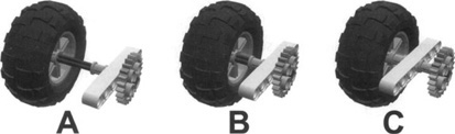
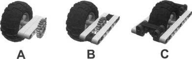
The first factor you need to consider is friction. You should take all possible precautions to minimize it. This is especially true where the structure attaches to the wheels because it is there that you transfer all the weight to the wheels by way of the axles. The wheel acts as a lever: The greater the distance from its support, the greater the resulting force on the axle. Such forces tend to bend axles, twist beams, and produce plenty of friction between the axle and the beam itself. For this reason, it’s important that you keep your wheel as close as possible to its supporting beam. Figure 6.7 shows three examples: “a” being the worst case and “c” the best.
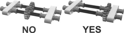
It is also a good idea to support the load-bearing axles with more than a single beam whenever possible. The three examples shown in Figure 6.8 are better than those in Figure 6.7, with 6.8c being the best among all the solutions shown so far. The use of two supports—one on either side of the wheel, as on a bicycle—avoids any lever effect created by the axle on the support, thus reducing the friction to a minimum.
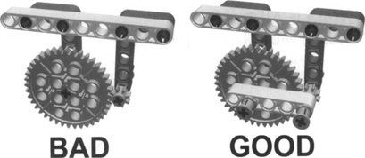
Having your gearing as close as possible to your supporting beams is just as important (see Figure 6.9). Positioning your gears next to supports will help to reduce or eliminate any gear slippage. If you do not place your gears near supports, the axles they are attached to may bend a little, which might allow the gears to slip when they are placed under load.
It is also important to place supports in the same orientation as the gears. If your gears are oriented vertically, your main support should be in the vertical direction. When placed under load, the majority of the force being placed on the gears and axles will tend to push them away from one another, so your support needs to be oriented to resist that force. Likewise, if your gears are in a horizontal orientation, your supports should be horizontal as well. Figure 6.10 illustrates this idea. In Figure 6.10, the main supports for the gears are placed vertically, while the gears are lined up horizontally with each other. When placed under load, the gears are going to try to push away from one another, primarily in the horizontal direction. Because there is little support in the structure to resist this, there is a good possibility that the gears will slip. Simply placing a short beam between the two gears connecting the two axles together will reduce the possibility of gear slip.
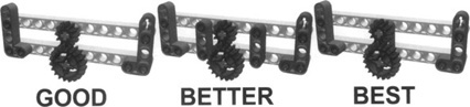
Ideally, the supports would be exactly in-line with the axles so that the axles would run through the holes in the beam being used for support. However, that is not always possible. In these cases, placing the supports as close as possible to the gears is advisable. Figure 6.11 shows three possible options, with “a” being the worst and “c” the best.
The position of the NXT has a strong influence on the behavior of mobile robots. It’s actually the shape and weight of the whole robot that determines how it reacts to motion, but the NXT (with batteries) is by far the heaviest element and thus the most relevant to balancing load. Recalling the concept of inertia will explain why balancing load is important. As explained earlier in this chapter, any mass will tend to resist a change in motion—in some cases, to resist acceleration. The greater the mass, the greater the force needed to achieve a given variation in speed.
The following example summarizes all the concepts discussed so far in this chapter. You can build the chassis shown in Figure 6.12 using only parts from the NXT kit. Its apparent simplicity actually conceals some trickiness. Let’s explore this together.
The motors are integrated into the chassis for this robot. They provide the power for movement and act as structural components. The upper beams are attached to the motors and lower beams using two L-shaped beams for improved rigidity. In front, the two sides of the robot are connected using two horizontal beams. The upper is designed to hold up under compression, and the lower resists tension forces. Two separate supports also help to increase the rigidity of the entire structure. Figure 6.13 shows the bottom view of the robot.
Wheels are placed as close as possible to the supports to reduce any lever effects that could introduce more friction into the system. The axles are also supported on both sides of the motors. The motor hubs tend to bend and move a little bit, so the axles are supported on both sides of the motor to further reduce any lever effects.
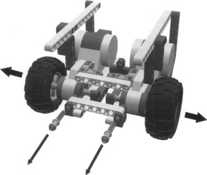
This platform is also very modular. Even though the motors are tightly integrated into the chassis, this platform comes apart easily so that each individual subassembly can be worked on and modified. The caster wheel assembly simply pulls off the back of the platform, as shown in Figure 6.14
Once you have removed the rear caster assembly, remove the two axles and bushings from the 7-length beam on the front, and then remove the beam. With a gentle pull, the left and right drive assemblies will separate from each other. You now have the three separate subassemblies that make up the robot platform (see Figure 6.15). Even the wheels can be easily removed for use elsewhere.
The truth is that if you own only the NXT kit, you probably won’t have enough parts to build another robot unless you dismantle at least most, if not all, of your existing robot. If you have more LEGO TECHNIC parts, however, you might be able to leave your platform or a select subassembly intact and reuse other parts in a new project.
This robot is a good platform to use to experiment with load and inertia. Write a very short program that moves and turns the robot. You don’t need anything more complex than the following pseudocode example, which will drive your robot briefly forward and backward, and make it turn in place:
start left & right motors reverse
wait 2 seconds
stop left & right motors
wait 2 seconds
start left & right motors forward
wait 2 seconds
start left & right motors reverse
wait 2 seconds
stop left & right motors
wait 2 seconds
start left motor forward
start right motor reverse
wait 2 seconds
stop left & right motors
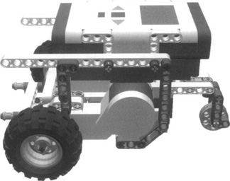
Place your NXT in different locations and test what happens. When it is slightly forward of the main wheel axles (see Figure 6.16), the caster wheel tends to lift off the ground when quickly switching from forward to reverse. This creates an unstable condition that could result in the robot failing to work properly.
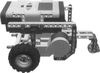
As you move the NXT rearward toward the caster wheel, the robot becomes more stable (see Figure 6.17). However, too much weight on the rear caster wheel is not the best position either. The more weight placed on a caster wheel, the poorer it will perform. Too much weight and it may not work at all.
Proper positioning of the load would be somewhere in between. For this platform, ideal placement of the NXT would be just above or a little behind the front drive wheels (see Figure 6.18). The drive wheels, not the caster, will carry most of the robot’s weight. The NXT is also not so far forward that the whole robot becomes unstable.
Some of you may have a substantial collection of LEGO pieces besides those that came with your NXT kit. Many of them may be studded LEGO TECHNIC pieces. Because the NXT kit comprises almost exclusively studless pieces, what should you do with all your studded LEGO TECHNIC bricks? Should you throw them away? Absolutely not! Like all LEGO pieces, studded and studless TECHNIC pieces are specially designed to fit well together, and using both in robotic creations can allow for some very interesting innovations. Sometimes creations using both studded bricks and studless beams are called hybrid creations, because they are a mixture of studded pieces and building techniques and studless pieces and building techniques.
We already discussed connecting legacy motors and sensors to the NXT with converter cables. Figure 6.19 shows some ways that you can attach legacy motors and sensors to studless beams so that you can include them in your robotic creations.
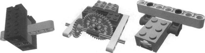
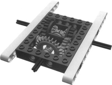
As discussed earlier in this chapter, pure studless assemblies often have more flexibility than similar studded assemblies. Oftentimes this is okay, even desirable, but sometimes it isn’t. Figure 6.20 shows a differential assembly using a special studded TECHNIC brick to house the differential gearing. Studless beams attached to the sides of the TECHNIC brick show how you can integrate studded and studless pieces in this assembly. As discussed in Chapter 2, the spacing between gears is very important, especially when using a crown gear. A structure using studless pieces to house the differential and gear assembly could have been built, but it would probably have used more pieces and been more flexible than the single TECHNIC brick. This is an example where using both studded and studless LEGO elements have resulted in a better assembly.
Another reason to combine studded and studless elements may be to attach studded LEGO plates to your creation to hide mechanisms and give it a clean outer appearance. Simply pinning studded LEGO TECHNIC bricks to your studless beams and attaching plates to those bricks can accomplish this. You may even want to add your RCX to your NXT robot. Adding studded TECHNIC bricks to your studless chassis will give you studded mounting points for your RCX. You can use the same method to attach a stationary studless creation to a LEGO base plate.
Recalling the key ideas we’ve presented in this chapter will serve you well in building LEGO robots with your NXT.
Using the studless building techniques—such as how to connect and brace parallel beams—will help to make your robot chassis strong and reliable. Remember that the proper placement and attachment of beams will do more to create a strong chassis than simply adding more parts. Keep in mind that a solid yet lightweight structure is the goal.
Modularity will allow you to reuse some components in other projects. It will also allow you to move entire subassemblies from one robot to another. You can also modify or rebuild individual subassemblies without having to change the entire robot. Modular building will also help if you need to take your robot apart for transport or storage.
Balance is the key to stable vehicles. Keep the overall mass of your mobile robots as low as possible to reduce inertia and its poor effects on stability. Experiment with different placements of the load, mainly in regard to the NXT, to optimize your robot’s response to both acceleration and deceleration and to improve stability.
Keep in mind that the ideas presented in this chapter are suggestions only. They are intended only to aid you in developing your own successful building style. Sometimes you may be able to use all of them in a single robot, and other times you may be able to apply only a few of them. These ideas aren’t rules. It may be possible to violate one or more of them at a time and still create a successful robot. Use them as a guide, but feel free to abandon the main road whenever your imagination tells you to do so.