
Solutions in this chapter:
Motors will be your primary source of power. Your robots will use them to move around, lift loads, operate arms, grab objects, pump air, and perform any other task that requires power. There are different kinds of electric motors, all of them sharing the property of converting electrical energy into mechanical energy. In this chapter, we will survey different kinds of LEGO motors and will discuss how to use, mount, connect, and combine them.
Before entering the world of motors, we would like to introduce you to some basic concepts about electricity. You should be aware of a very important distinction concerning the two types of electrical current: alternating current (AC) and direct current (DC). Alternating current is the type of electricity that comes out of the wall outlets in your house, whereas batteries are the most typical source of direct current. All the electric LEGO devices, including motors, work with DC only.
To understand what DC is, imagine a stream of water going down a hill. Electricity flowing through a wire is not very different: When you connect a battery to a device such as a lamp or a motor, you enable a circuit through which electricity flows more or less like water in a stream. You know that batteries have positive (+) and negative (-) signs stamped on them: These signs indicate two poles, where the electrons flow from minus to plus, as though the minus pole were the top of the hill and, as a result, the current flows from plus to minus. You can place a water mill along a stream to convert the energy of water into mechanical energy; similarly, an electric motor converts an electric flow into motion. What would happen to the water mill if you could reverse the direction of the stream? It would change its direction of rotation. The same happens to DC motors. Every motor has two connectors, one to attach to the negative pole and the other to connect to the positive end of a DC source. You can imagine the current flowing from the positive pole of the battery into the motor, making it move and then coming out again to return to the negative pole of the battery. If you reverse the polarity, that is, if you swap the wires between the motor and the battery, you will change the direction of the stream and, thus, the direction of the motor.
Continuing with our hydraulics metaphor, how would you describe the quantity of water that’s flowing in a stream? It depends on two factors: the speed of the water, and the width of the stream. Both of them have an influence on the kind of work your mill can perform. In the realm of electricity, the speed of the stream is called voltage, and its width (its intensity) is called current. They are respectively expressed in volts (V) and amperes (A), or sometimes in their submultiples, millivolts (mV) and milliamperes (mA). The amount of work that an electrical flow can perform—for example, through a motor—depends on both of these quantities. To be more precise, it depends on their product, called power, and is measured in watts (W).
All motors are designed to run at a specific voltage, but they are very tolerant when it comes to decreases in the supplied voltage. They simply turn more slowly. However, if you increase the voltage above the specific limit for a motor, you stand a good chance of burning it out.
Current has a different behavior. It’s the motor that “decides” how much current to draw according to the work it’s doing: The higher the load, the greater the current. The situation you should avoid at all costs when working with your NXT is to have the motor stall (it is connected to the power source but something prevents it from turning). What happens in this case is that the motor tries to win out against the resistance, drawing in more current so that it can convert it into power, but as it doesn’t succeed in the task, all that current becomes thermal energy instead of mechanical energy—in other words, heat. This is the most dangerous condition for an electric motor. And here is where use of clutch gear comes into play, limiting the maximum torque and thus preventing stall situations. You will discover later in the chapter that the NXT also has an active role in protecting your motors from dangerous draws of current.
Every motor contains one or more coils and permanent magnets that convert electrical energy into mechanical energy, but you don’t really need to know this level of detail. What you, as a robot builder, must remember is that every motor has a connector through which you can supply it energy, and an output shaft which draws the power. The current LEGO TECHNIC line includes several motors. All of these are 9V DC motors and have different properties and features for various applications (as shown in Figure 3.1): the ungeared motor (a), the geared motor (b), the micromotor (c), the RC motor (d), and the NXT servo motor (e). Recently, LEGO also introduced the Power Function system, which includes two more motors (f and g). There are other special motors as well: the train motor, the geared motor with battery pack, and the Micro Scout unit. These are less common, less versatile, and less useful to robotics than the ones featured here, so we won’t be examining them here.

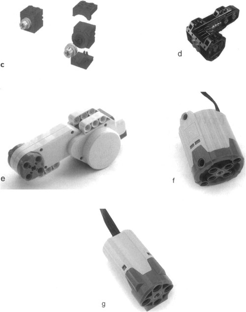
Table 3.1 summarizes the properties of these motors.
Table 3.1. Properties of the LEGO TECHNIC Motors
Minimum Current (No Load) | Maximum Current (Stall) | Maximum Speed (No Load) | Speed under Typical Load | ||
|---|---|---|---|---|---|
Ungeared motor | 9V DC | 100 mA | 450 mA | 4,000 rpm | 2,500 rpm |
Geared motor | 9V DC | 10 mA | 250 mA | 350 rpm | 200-250 rpm |
Micromotor | 9V DC | 5 mA | 90 mA | 30 rpm | 25 rpm |
RC motor | 9V DC | 160 mA | 3.2 A | 1,300 rpm | 900-1,200 rpm |
NXT servo motor | 9V DC 12 V DC[*] | 60 mA | 2 A | 170 rpm | 100-130 rpm |
Power Function large motor | 9V DC | 60 mA | 2 A | 250 rpm | 175-200 rpm |
Power Function medium motor | 9V DC | 60 mA | 2 A | 450 rpm | 325-375 rpm |
[*] Handles for short periods; however, this is not recommended for extended periods. | |||||
The ungeared motor (a) has been the standard LEGO TECHNIC motor for a long time. Its axle is simply an extension of the inner electric motor shaft, and for this reason we called it ungeared. Electric motors usually rotate at very high speeds, and this one is no exception, turning at more than 4,000 rpm (revolutions per minute). This makes this motor a bit tricky to use, because it requires very high reduction ratios for almost any practical application, leading to very cumbersome and complex geartrains. Add the fact that it draws an amazing amount of current, and you get a pretty good picture of how difficult it can be.
This motor is still easy to find in the shops of many countries as an expansion pack (8720), but you may want to consider other types of motors for the reasons mentioned in the preceding paragraph. In this book, you won’t find any example that includes the ungeared motor. Nevertheless, if you already have one, you can safely use it; it won’t damage your NXT or be damaged itself. The only risk you’re taking is that, under heavy loads or stall situations, it drains your batteries very quickly.
The geared motor (b) features an internal multistage reduction geartrain and turns at about 350 rpm with no load (typically 200-250rpm with medium load). It’s much more efficient than the ungeared kind, and it has low current consumption. It also uses more compact geartrains. If you have the old MINDSTORMS RCX kit, you already have two of these.
The micromotor (c) is a geared motor as well. It’s geared down so much that its output shaft turns at approximately 30 rpm. Nevertheless, its torque is incredibly low, well below 1 Ncm. It is also surprisingly noisy, and very easy to jam. At this point, you might wonder why you should ever consider this motor, but the answer lies in its name: because it’s micro. Sometimes the size of the motor is more critical than the amount of torque and speed needed. To be used, it requires some special mounting brackets, and a small pulley to connect to its shaft (Figure 3.1c).
The RC motor (d) is a geared motor with approximately 1,300 rpm without load and 900 rpm under medium load. Output is delivered through a bush to join axles. It features two outputs turning at different rpms and opposite directions. The farther output is running at about 1,000 rpms without load. The higher rpm output delivers lower torque than the other.
The NXT servo motor (e) is not only geared, but also has other electronics to provide precise positioning information. This motor runs at lower rpms, but has very high torque. In the next section, you will see how to connect these motors to your NXT.
The new Power Function system motors (f and g) are also geared motors and have a special electrical connector. These motors are compact and versatile for use in small places.
Servo motors in industrial applications are different from regular motors because of their capability to precisely rotate the motor shaft. This is achieved by special electronics built into the motors. Similarly, the NXT servo motors are advanced in their capabilities and precision. Philippe Hurbain’s Web site, NXT motor internals, is an excellent place to learn more about the internals of these motors (refer to Appendix A), and some of his material is included in the following section.
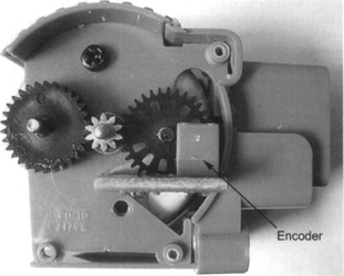
NXT servo motors have a built-in optical encoder that keeps count of rotations of the motor shaft (see Figure 3.2). This encoder is accurate up to 1 degree of motor rotation. You can use this property from your program for precise movement or positioning:
while (nMotorEncoder[motorA] < 1000)
// wait for motor to reach a specific location
{
. . .
}
This property can also keep two motors synchronized with each other and move your robot along a straight line.
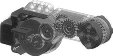
The NXT servo motor also has built-in gears to reduce the rpms and increase the torque (see Figure 3.3). This desirable feature makes it easier to build robots without excessive geartrains, thereby reducing the complexity and size of your robot.
The NXT servo motor is designed for integration into the studless construction of your robot. The large rounded end is about 7 units (TECHNIC holes) high and 5 units wide, whereas the orange end of the motor is 3 units wide and 3 units high. Overall, the motor is about 14 units long, and due to its unusual shape, it requires some experience to mount on your robot. In the following paragraphs, we will discuss a few common solutions, as well as how to take advantage of this shape in your construction.
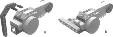
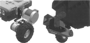
Despite its unusual shape, the NXT servo motor fits well within the standard TECHNIC grid. The elongated shape of the motor makes it easy to integrate with the primary chassis of your robot. While designing your robot, try to integrate the motors in the early stages of the design, or build the robot assembly around the motors. In Figure 3.4 (a), you can see that the large rounded end has two built-in three-hole beams on top, which you can connect to your robot’s structure using TECHNIC pins. In Figure 3.4 (b), you can see the holes which can be connected using TECHNIC double pins.
Note
The pictures here are mainly meant to illustrate possibilities. So, in order to let you visualize, we didn’t lock the pins and the beams to the motor. In actual applications, you will complete the assembly and extend it for your needs
In Figures 3.4a and 3.4b, the top-right end of the motor has a through hole, and the axle fits snugly into it. For simple mobile robots, you can choose to attach wheels directly onto this axle. This end also has one built-in three-hole beam to which you can connect your robot’s structural beams or pins.
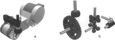
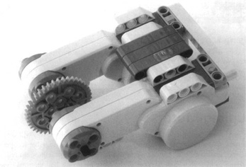
When it comes to transferring power along a different axis or to a different location, you have plenty of choices, but essentially you will use gears. With the high torque delivered from the NXT motor, belts are not very effective unless you can tolerate a lot of slippage. Figure 3.5(a) shows one such assembly. Experiment with other pairs, as shown in Figure 3.5(b), to see which best suits your needs.
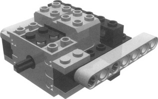
As we said earlier, NXT motors are suitable for integration into your robot’s structure, but when you need to reuse them in other projects, it’s a challenge to keep them easily removable, while keeping the rest of the robot intact. When planning for a removable motor in your design, consider attaching motors with TECHNIC pins and a stop bush (see Figure 3.6). These bushes are easy to hold, and it’s also easy to use them to pull the pins. Try to keep the connections along a single plane which effectively separates the motor from your robot’s structural design, thus keeping your robot intact when the motor is removed.
Have you wondered how to connect the studded motors to studless beams? If you have RCX motors, the easiest method is to use some of your TECHNIC bricks with holes to mount the motor (Figure 3.7). Use the 1 × 2 plates with rails as brackets for the motors, and use TECHNIC bricks to hold the motors in place. Mount the studless beams over the TECHNIC bricks. Also, for additional stability at the back, you can use a TECHNIC axle joiner with four pins.
The MINDSTORMS NXT wiring system uses jacks similar to telephone jacks. Though they look similar, you cannot use regular phone wires in them. That also will keep some creative minds from plugging the NXT into the telephone network.
As we already explained, these motors are DC motors, and therefore, they are sensitive to the polarity with which you connect them. With NXT wiring systems, you cannot go wrong with the polarity. But if you are connecting old motors with the NXT using a compatibility cable, you will have to consider the polarity or control this property from your program.
How can you test your motors without adjusting your programming? Here are some suggestions:
The NXT console Power on the NXT and press the scroll button on your NXT console until it reads NXT Program. Select the program using the center orange button. This is a built-in test program which allows you to create a mini program on the NXT. You can control up to two motors in this mini program.
The RobotC software You can use RobotC to directly control the NXT. From the Robot menu, select the NXT Brick submenu, followed by the Poll Brick submenu. In the resulting window, you can control the motors directly through the Set values into NXT interface.
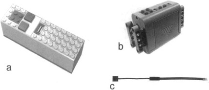
An external battery box Various kinds of battery boxes are available, as shown in Figure 3.8 (a) and (b). With a box such as this and an NXT converter cable such as the one shown inFigure 3.8 (c), you can test your motor without the NXT.
A Bluetooth device You can use a Java-capable and Bluetooth-enabled cell phone to send messages to the NXT. Using a joystick or command wheel on your phone you can control two motors on the NXT. This is very useful for testing your robot during the building phase, especially when it is hard to reach the NXT console.
Other sources All the components of the LEGO 9V electric system are compatible with each other. If you have a LEGO train speed regulator, or a Control Center unit, you can safely use them to run your motors using an NXT converter cable.
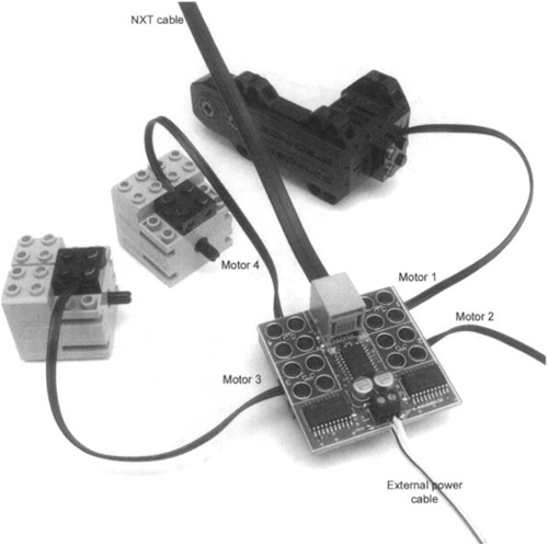
In some cases, you want to control more motors than the NXT ports can support. Or you may want to attach power-hungry motors to your robot, but conserve the NXT battery. For such applications, you can use a Motor Multiplexer from Mindsensors (see Figure 3.9). This multiplexer can conveniently attach up to four additional motors using RCX-style connectors. It supplies power to these additional motors from an external battery, thus conserving the NXT battery. You can also connect NXT servo motors using a converter cable.
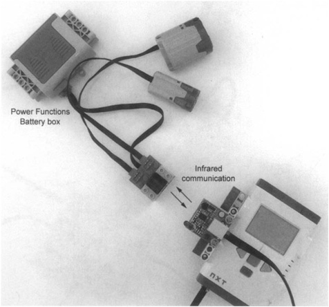
The new Power Function system is also a 9V DC system like the NXT. Because these modules use a different electrical connector, it will be a bit of a challenge to use these motors directly with NXT robots. LEGO will be developing a converter cable to connect the Power Function system with the old 9V system. And with the converter cable already developed between the NXT product and the old LEGO 9V system, it will be possible to use the LEGO Power Function together with MINDSTORMS NXT using these converter cables.
The Power Function system has its own battery box and an infrared controller (see Figure 3.10). Mindsensors will be extending its NRLink to support communication with this controller. Using NRLink, the NXT can send commands to control the Power Function motors. This way, you can use the Power Function battery box on your robot, and conserve the NXT battery.
You know that your program can control the power of your motors. In fact, using the RobotC setMotorPowerQ method will set the power in the range of-100 to +100, where negative values indicate reverse direction:
// enable motor speed regulation
nMotorPIDSpeedCtrl[motorA] = mtrSpeedReg;
. . .
// move at half speed
motor[motorA] = 50;
But what happens when you change this number? And why do we care? There are different ways to control the power of an electric motor. The LEGO train speed regulator controls power through voltage: The higher the voltage, the higher the power. The NXT uses the same approach as the RCX, called pulse width modulation (PWM).
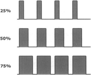
To explain how this works, imagine that you continuously and rapidly switch your motor on and off. The power your motor produces in any given interval depends on how long it’s been on in that period. Applying current for a short period of time (a low duty cycle) will do less work than applying it for a longer time. If you could switch it on and off hundreds of times a second, you would see the motor turning in an apparently normal way; but under load you would notice a decrease in its speed, due to a decrease in the supplied power (Figure 3.11).
This is exactly what the NXT does. Its internal motor controller can switch the power on and off very quickly (an on/off pulse every millisecond), at the same time varying proportion between the on and off pulses. At power level 1, for every 100 pulses applied, the motor receives one on pulse; at power level 25, for every 100 pulses applied, the motor receives 25 on pulses; and so on, until you reach level 100, when all pulses are on.
Why do we care about this technical stuff? Because this explains that you aren’t actually controlling speed, but power. LEGO motors are very efficient, and when the motor has no load or a very small load, lowering the power level won’t decrease its speed very much. Under more load, you will see how the power level affects the resulting speed too.
Often, one would like to check whether the NXT servo motors are working properly. Two common problems encountered with motors are stalling and slipping. The former happens when the load on the motor exceeds its maximal power, leading to a “frozen” motor. Checking if your motors are stalled is relatively easy by monitoring the motor encoders. If the motor should be running but its encoder doesn’t increment (or it increments less than your threshold), it is stalled. Slipping occurs, for example, when your robot is stuck at a wall, but the wheels lose their grip and rotate in place. Detecting slip is more difficult than detecting stall. Guy Ziv at NXTasy.org has developed a Motor Power Meter NXT-G block that allows you to monitor the load on the motor. When the motor slips, its power is usually larger than that experienced during normal operation, which allows detection of slip conditions.
Controlling the power means also being able to brake your motor when necessary. For this purpose, the NXT features a sort of electric brake. Once again, let us explain how it works through an experiment.
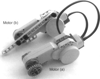
Assemble the motors as shown in Figure 3.12. Note that motor (b) is locked by a beam, resulting in a stall, effectively causing motor (a) to be shorted. We know that a short circuit sounds like a bad thing, but in this particular case we mean only that the circuit is closed. Don’t worry; your motor is not at any risk. Now try to turn the 24t with your fingers. You see? The motor offers a lot of resistance, and as soon as you stop turning, it stops too. Now disconnect motor (b) from the cable and try to turn the 24t again: It turns smoothly, and it continues to spin for a while after you have stopped turning it.
What happened? Not only is an NXT motor able to transform electricity into motion, it does the opposite too: It can be used to generate electricity. In our experiment, when motor (a) is shorted, the generated current is sent back into the motor, producing a force that resists the motion. This is a simple but effective technique which the NXT implements to brake the motor: When you set the motors to brake, the NXT not only switches the power off, but it also short-circuits the port, making the motor brake.
If you need more power for a task than a single motor can deliver, you will very likely need to mechanically couple the motors, meaning that they will work together to operate the same mechanism, sharing its load. It’s like when you have to move something really heavy and you call a friend to help you: Each member of the party bears only half the total weight. Though this rule works for all electric motors in general, a specific limitation applies when attaching multiple motors to the NXT: Its current-limiting device won’t allow the motors to draw as much current as they want. Consider it a constraint to the maximum power each port can pay out.
In Figure 3.13, you can see two motors connected using a single axle to a 40t gear wheel. People often wonder whether connections such as these are going to cause any problems to the motors. The answer is simply no. Unless you keep one of the motors stalled for more than a brief moment, they are not easy to damage. In applications such as the one in Figure 3.13, you just have to be sure the motor power of one motor doesn’t oppose that of the other. The NXT wiring won’t let you do it incorrectly. However, we suggest that you double-check your program to ensure that both motors are turning in the same direction.
It is true that no two motors turn at exactly the same speed, or output the same torque, but this doesn’t cause any conflict. A motor doesn’t know that another motor is cooperating on the same task. It simply reacts to the load, absorbing more current and trying to keep the speed. This works even if the motors are of different types, even if they are powered at different levels, and even if they are geared with different ratios.
If you’re not convinced of this, think of a simple vehicle propelled by a single motor. When the path becomes steeper, the load on the motor increases, causing it to reduce its speed. Essentially, the motor adapts itself to the load. The same happens when two motors work together; they share the load and mutually adapt themselves.
To make things easier, you can use the Synchronized Motors feature available in RobotC to run the motors together:
nSyncedMotors = synchNone; // No motor synchronization
. . .
nSyncedMotors = synchAC; // Motor 'C is slaved to motor 'A'
Have you ever tried riding a tandem bicycle? Your partner might be much weaker than you, but you would prefer him to pedal rather than simply ride along, watching the landscape.
NXT motors are easy and safe to use, but they require a bit of experience to get the most from them. You have seen that wiring NXT motors is very simple and you cannot go wrong with the polarity. The different mounting options require some knowledge and a bit of practice, especially if you need to keep the motors easily removable.
On the topic of coupling motors, this option is useful when you want to split a load over two or more motors to reduce their individual efforts. The only important thing to remember is that you must run them in the same direction to avoid any dangerous conflict situation in which one motor opposes the other.
As a general tip, we suggest that you make intense use of prototyping. Don’t wait to finish your robot to discover that a motor is in the wrong place or has not been geared properly. Test your mechanisms while you are building them.