
Solutions in this chapter:
Most robots are designed with some kind of mobility in mind. Motion makes your creatures animated and “alive,” and offers a limitless number of interesting, fun, and challenging projects with which to test your creativity and skills. Most mobile robots belong to one of two categories: wheeled robots or legged robots. Though legs provide an effective way to move on rough terrains, wheels are generally much more efficient on smooth surfaces.
In this chapter, we will survey some common wheeled mobility configurations, discussing some of their pros and cons. Please bear in mind that the chassis shown in the following examples are designed to highlight the details of gearings and connections, and for this reason, some of them need reinforcement to be used in actual robots.
If you have built some of the robots in the NXT-G Robo Center, or put together the test platform outlined in Chapter 6, you’re already familiar with the differential drive architecture. It has so many advantages, particularly in its simplicity, that it’s by far the most often used configuration for LEGO mobile robots.
A differential drive is made of two parallel drive wheels on either side of the robot, powered separately, with one or more casters (pivoting wheels) which help support the weight but that have no active role (see Figure 9.1). Note that it is called a differential drive because the robot motion vector results from two independent components (it’s of no relation to the differential gear, which isn’t used in this configuration).
When both of the drive wheels turn in the same direction at the same speed, the robot goes straight. If the wheels rotate at the same speed but in opposite directions, the robot turns in place, pivoting around the midpoint of the line that connects the drive wheels. Table 9.1 shows the behavior of a differential drive robot according to the direction of its wheels (assuming that when it’s in motion they run at the same speed).
Table 9.1. Behavior of a Differential Drive Robot According to the Direction of Its Wheels
Left Wheel | Right Wheel | Robot |
|---|---|---|
Stationary | Stationary | Rests stationary |
Stationary | Forward | Turns counterclockwise, pivoting around the left wheel |
Stationary | Backward | Turns clockwise, pivoting around theleft wheel |
Forward | Stationary | Turns clockwise, pivoting around the right wheel |
Forward | Forward | Goes forward |
Forward | Backward | Spins clockwise in place |
Backward | Stationary | Turns counterclockwise, pivoting around the right wheel |
Backward | Forward | Spins counterclockwise in place |
Backward | Backward | Goes backward |
At different combinations of speed and direction, the robot makes turns of any possible radius. This maneuverability, the capability to turn in place in particular, makes the differential drive the ideal candidate for a broad class of projects. Add to this the fact that it is very easy to implement, and you can understand why a significant percentage of all mobile LEGO robots belong to this category.
If tracking the robot position is one of your goals, again the differential drive is a good candidate, requiring very simple math.
There’s only one real drawback to this architecture: It’s not easy to get your robot to move in a perfectly straight line. Because no two motors have exactly the same efficiency, you will always have one wheel turning a bit faster than the other, thus making your robot turn slightly left or right. In some projects, this isn’t a problem, particularly those programmed for continuous route correction, such as following a line or finding a path through a maze. But when you want your robot to simply go straight in an open space, this problem can be really frustrating.
One of the most significant changes moving from the MINDSTORMS Robotics Invention System (RIS) to the NXT is the inclusion of rotation sensors (encoders) in the servo motors (Chapter 4 goes into detail on this). In a nutshell, the encoders allow motor rotations to be monitored to the nearest degree. This addition provides the means for your robot to drive straight. Combined with the NXT-G Move block, you can now build robots that go almost perfectly straight and auto-correct themselves along the way.
Although this new feature of the NXT system has provided new ways to keep your robot tracking straight, it is still important to understand the concepts behind differential drive mechanisms. In this chapter, we will discuss alternative approaches including both the sensor-based approach as well as using gears.
A more sophisticated approach that has several positive side effects requires you to introduce a feedback mechanism into your system, thus controlling each wheel with sensors and adjusting their speed according to the readings. This is what most of the “real-life” differential drives do. As noted previously, the new NXT servo motors have a high-resolution rotation sensor built right in, making this process very easy to do.
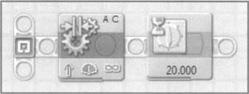
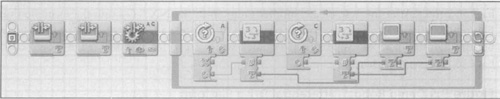
In fact, this is so easy to do that you can have a robot up and running in less than 15 minutes. Start by building a simple robot such as the TriBot from the NXT-G Robo Center. The only requirement is that you have two drive motors, each attached to a drive wheel. In the NXT-G, create a simple program using the Move block. This block is different from the standard Motor block in that it allows for two motors to be paired together so that the software can monitor both of their rotation sensors simultaneously to allow for automatic correction to keep them driving straight. Figure 9.2 shows a simple NXT-G program that will enable your robot to drive straight. The differential process is handled entirely within the Move block by “watching” the rotation sensors on each motor. If one of them falls behind, the NXT will increase the power on the lagging motor to allow it to catch up with the other. In addition to this, the software may also reduce the speed of the other motor if the lagging motor does not catch up in time.
To test this feature, create the robot and set the motor speed such that you can follow along beside the robot. As it is driving forward, use your finger to slow down one of the wheels. You should see it speed up that wheel after you let it go. If you hold the wheel long enough, the NXT should stop the other drive motor.
As noted earlier, it is important to understand the concept behind a differential drive mechanism. To do this, we demonstrate using the LEGO differential gear drive mechanism in Figure 9.3.
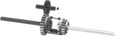
It functions in much the same way as a vehicle differential operates, the basic principle being that the motor drives the differential housing via a main drive gear, “A”. The differential is geared such that both wheels turn at the same direction and speed, “B” and “C’. This enables smooth transfer of power when a vehicle is turning. On the flip side, if one wheel is on a slick surface (e.g., ice), most of the power will divert to it as there is less friction. You have likely heard the term limited slip differential in vehicle discussions—this feature uses mechanical or hydraulic clutches to divert power away from the wheel that is slipping to the one that is not. This way, the differential functionality is still available, but it is monitored so that slip is limited. Most vehicles today use some form of this mechanism. A LEGO-only sample of this is shown later in this chapter, and Chapter 2 also has some additional information on this.
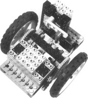
If you connect the drive wheels with a differential so that one wheel enters the differential with a direction that’s inverted with respect to the other, the body of the differential itself should stay still when the wheels rotate at the same speed. Figure 9.4 shows a standard differential drive platform. Both NXT motors drive each wheel directly, and are connected to the differential unit via a series of gears such that their directions are inverted. When both motors are driving the same speed, the differential unit will remain stationary. If the motors are not in sync, the differential will turn for the duration that the motors are not in sync.
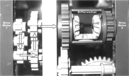
Why would you do this, you ask? Well, it provides a means to monitor when motors are driving at different speeds. When they are driving in sync, the differential will remain stationary. As their speeds vary, the differential will slowly turn.
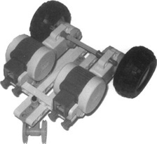
Trying to watch the differential to see any change while your robot is moving is quite difficult. Figure 9.5 shows the top of a demo robot built with the aforementioned differential drive and provides an analog method of measuring differences among motor speeds. The large 40T gear is linked to the differential unit (see Figure 9.4). On top of it is a wedge that is pointed directly at a stationary wedge. This is a crude measurement device and marks the start point for when the robot is stopped. As the robot drives along, the 40T gear will turn if one motor is slowed relative to the other. You can test this by creating the robot, and instead of using a Move block in the NXT-G, try using two Motor blocks (1 for each motor). Do a trial and force one wheel to slow down. You should notice the wedge move and not recover back to center. After this test, create another program in the NXT-G using the example from Figure 9.2. When trying to slow one motor, you may notice a temporary shift in the wedge, but through the NXT software, the Move block will correct this and the wedge should come back to center somewhat.
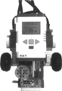
Of course, you might ask why you should bother creating a crude analog measurement device such as this when you can use the NXT display to simply show the rotation values for each motor. Good idea! Figure 9.6 is a sample NXT-G program that will drive the aforementioned robot forward for a period of time and display the encoder values for both motors on the screen.
When running the robot, try slowing down one wheel while it drives, and you will see the encoder values change, but be quick, as the Move block will correct this. If you stop one wheel completely, you will notice the other one stop shortly afterward.
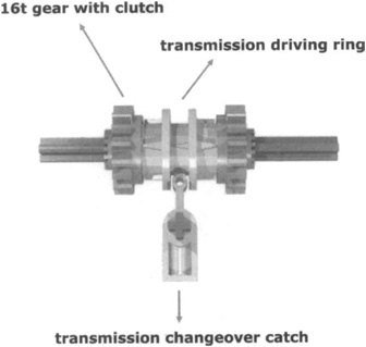
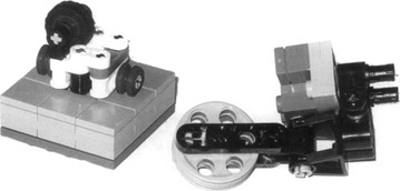
If you find yourself using some of the older RIS-based motors that don’t have built-in rotation sensors, you are still in luck. A more radical solution is to lock the wheels together when you need to go straight. This system is very effective, making your robot go perfectly straight, but it requires a third motor to activate the locking system as well as some additional gearing, which makes the solution less than compact. Figure 9.7 shows an example using legacy MINDSTORMS parts of a locking mechanism that requires special parts: a dark gray 16t gear with dutch, a transmission driving ring, and a transmission changeover catch, which combine in a sort of clutch mechanism (see Figure 9.8). That special gear has a circular hole instead of the standard cross-shaped hole; thus, it rotates freely on the axle. The driving ring should then be mounted on an axle joiner. When you push the driving ring into the gear (with the help of the changeover catch), the gear becomes solid with the axle.
Casters are another key factor in getting your differential drive moving and turning smoothly. Most often, though, they are not given enough consideration. Figure 9.9 shows a typical coupled caster wheel assembly. Unfortunately, its design is limiting and it will skid or jam. It uses two wheels coupled on the same axle and doesn’t allow the wheels to turn independently. Keep the assembly gently but firmly pressed on a table, and try to rotate it in a tight turn—it doesn’t turn very well, does it? In fact, unless you let one of the wheels skid, it doesn’t turn at all.
The casters shown in Figure 9.10 get much better results. The one on the left uses a single wheel, thus avoiding the problem entirely. The one on the right, which is more solid, uses two free wheels that allow the caster to turn in place without friction or slippage problems. The difference is in the wheel hubs. In the assembly on the left, the axle turns with the wheel, whereas the one on the right has the wheels spinning on the axle. Other casters are shown in Figure 9.11.
The choice of using one or more casters depends on the task for which the robot is designed. A single caster is enough for most applications, but two casters at the front and rear of the robot are a better option when stability is important.
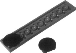
In some cases, as with a simple robot of limited weight that has a smooth surface on which to navigate, you can substitute the caster with inverted round tiles or other parts that provide limited friction when coming into contact with the floor (see Figure 9.12).
Another less widely used method for casters is a plastic ball. If your robot is running on a smooth surface, a large ball acts quite well as a caster. Figure 9.13 shows a demonstration of this connected to two NXT motors. The caster cage unit is mounted such that it cups the ball and allows for some freedom of movement for the ball. The entire cup structure is also able to pivot up and down as well so that it handles bumps better. The advantage of this approach is that you have no caster wheels to get caught up, and the ball will turn if it can; otherwise, it will simply drag along the surface. As long as the surface is smooth, it works like a charm. This approach will not work well if you are running your robot across a surface that has a rubbery texture. Although the ball turns freely within the cup structure, it is still subject to friction within it.
A skid-steer drive is a variation of the differential drive. It’s normally used with tracked vehicles, but sometimes with four- or six-wheel platforms as well. For tracked vehicles, this drive is the only possible driving scheme. Good examples of skid-steer drives in real life are excavators, tanks, and a few high-end lawnmowers.
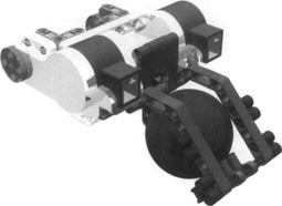
Figures 9.14 and 9.15 show pictures of Bryan Bonahoom’s NX Tracker and Dave Astolfo’s UNV tracked robots. Both use a tracked skid-steer drive with UNV employing an additional set of tracks at the front that can pivot to provide additional navigation functionality. Each track is powered by its independent motor.
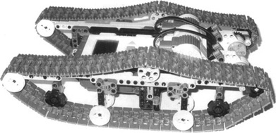
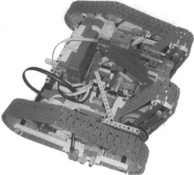
The advantage of a skid-steer drive is its capability to turn on the spot, which allows vehicles of this type to operate in tight areas. The downside to this is that when turning there is a lot of friction on surfaces such as carpets. If you are running rubber tracks, you also get the added advantage of climbing capability, but if you are running ones such as those shown here, expect some slippage—unless, of course, you find some rubber grommets that just happen to fit the TECHNIC-size pin holes in each link.
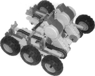
A wheeled skid-steer drive requires a trickier setup. You must transmit the power to all the wheels; otherwise, your platform won’t turn smoothly, or it might not even turn at all. The model shown in Figure 9.16 uses a number of 24t gears connected by a common chain drive for each side receiving power from two motors, as in the tracked version. This platform serves well as it is strong, fast, compact, and light. You can add an NXT, and there is plenty of room for sensors, or even a grabber arm.
Tracked robots are easy to build and fun to see in action, thus placing them among the favorites of many builders. Just as with differential drives, when the tracks go in the same direction, the robot goes forward; differences in their speeds or directions make the robot turn; in-place steering is possible too. Skid-steer drives also share with differential drives the same difficulties in getting them to move in a straight line.
Here is where the similarities end, and some peculiarities of skid-steer emerge:
Tracks have a better grip than wheels do on rough floors and terrains, but this is not true on smooth surfaces.
Tracks introduce more friction which uses up some of the power supplied by the motors.
The unavoidable skidding intrinsic in the nature of these vehicles makes them absolutely unsuitable for applications where you need to determine the position by utilizing the motion of the robot.
A steering drive is the standard configuration used in cars and most other vehicles that features two front steering wheels and two fixed rear wheels. Thankfully, it’s suitable for robots too. You can drive either the rear or the front wheels, or all four of them, but the first is by far the easiest solution to implement with LEGO parts, so this is what we’ll cover here. Though less versatile than differential drives, and impossible to steer in place or in very tight turns, this configuration has many advantages: It’s very easy to drive straight, and it’s very stable on rough terrain. Figure 9.17 shows a simple steering platform created by Laurens Valk (Appendix A).
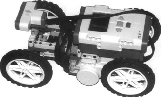
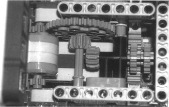
The mechanics are straightforward. Two motors drive the rear wheels (one for each) and one motor drives the steering mechanism. Unlike a skid-steer drive, this setup provides separate control of the steering and drive motors, allowing for more precision in steering, but lacksing the capability to turn in place. The steering unit (see Figure 9.18) is geared to offer fine control over the steering and uses a rack and pinion structure where a series of gears combine with a special plate with teeth, a sort of “unrolled gear” (the rack) which is connected to the wheels to provide steering. This is also a nice demonstration of studless building techniques.
Designing & Planning...
Using Ackerman Steering for Smooth Turns
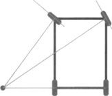
True-life steering vehicles implement a more sophisticated scheme called Ackerman steering{from the name of the person who first studied it). In our simple design, the steering wheels turn at the same angle, but this is not entirely correct—during turns, the inner wheel goes along a tighter bend than the outer one. During large radius turns, the difference is small and its effect negligible. In tight turns, however, the effect becomes quite noticeable, causing one of the steering wheels to skid. Ackerman’s steering system is designed to compensate for the different turning angle of the inside wheel, thus eliminating any skidding. The theory says that the vehicle turns smoothly when the “lines” extended from every wheel axle meet and revolve around one common point (see Figure 9.19).
Building an Ackerman scheme with LEGO is definitely possible with a little thought and planning.
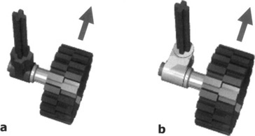
When you build the steering assembly, you can move the wheel behind its pivoting axle for self-centering steering (an advisable property in many situations). In version “a” in Figure 9.20, you see a wheel mounted just below the pivoting axle, which does not affect the steering. If you mount the wheel behind its steering column, friction causes the dynamic forward motion of the car to push the wheels toward the rear, resulting in a self-centering action. Look at the design of a shopping cart, and you will see that the actual wheel contact area is behind the pivoting axis. The more you move the wheel behind the pivoting axis, as in versions “b” and “c,” the more self-centering you get. Don’t ever mount the wheel in front of the pivoting axle, as in version “d.”This will make your steering unstable. In fact, the wheel will tend to go toward the rear, causing your car to turn spontaneously.
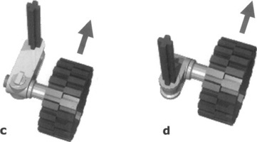
We encourage you to experiment with these concepts, building a simple chassis and exploring the properties of the various assemblies shown in Figure 9.20.
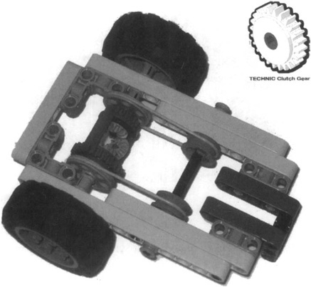
The steering drive is a suitable configuration for rough terrains, because it’s very stable on its four wheels. You can improve the grip of the wheels on the ground by using some kind of suspension. It’s very important that none of the drive wheels permanently loses contact with the ground; otherwise, the differential would find the path of least resistance and transfer all the power to that wheel, resulting in the wheel spinning and your robot becoming immobilized.
A limited slip differential can help reduce this problem (see Figure 9.21) by connecting the wheel axles to a common supplementary axle through pulleys and belts. The belts tend to keep the driven axles rotating at the same speed, but during turns they slip a bit on their pulleys, allowing the wheel to adjust their speeds. Should a wheel lose contact with the ground, the belts will still be able to transfer a good portion of power to the other wheel. Alternatively, you could try to integrate two TECHNIC clutch gears (see Figure 9.21, top right). Simply replace the two wheel hubs with the clutch gears, move the axle closer, and substitute 2×24T gears in place of the pulleys attached to the differential. The TECHNIC clutch gears have a measured amount of slip built into them which will cause the outer (white) section to turn independently from the inner (dark gray) axle unit when enough force is applied.
A synchro drive uses three or more wheels, all of them driven and steering. They all turn together in sync, always remaining parallel; thus, the robot changes its direction of motion without changing its orientation.
Synchro drives are quite challenging to build with LEGO parts. Years ago, these types of robots were few, but, if you navigate the Internet now, you can find many well-designed LEGO synchro drives out there.
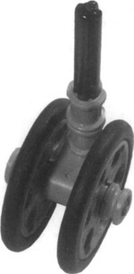
To make a full 360-degree synchro drive and avoid any limitations in its turning capability, the key point is to transfer motion along the pivoting axle of each wheel. The simplest approach requires a special part called the turntable, a large, round, rotating platform usually employed in LEGO models to support revolving cranes or excavators (see Figure 9.22).
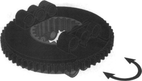
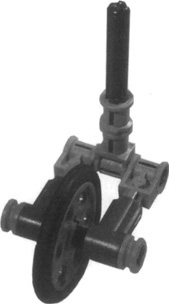
You can attach two pulley wheels and drive it with an axle that passes through the center of the turntable. In Figure 9.23, you can see an example of this technique. Notice the orientation of the turntable—the black side is connected to the wheel assembly. This is necessary because the wheel must be connected to the part of the turntable that gets rotated by the external gear. This way, you can attach the top (gray) side to the stationary portion of the robot with the black section being driven by the common steering motor.
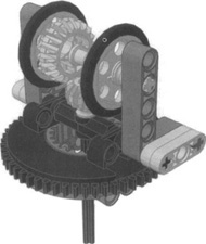
To build a complete synchro drive, you need at least three of these turntables. Then you have to connect them so that one motor can drive all the axles at the same time, while another can turn all the wheels in sync.
In Figure 9.24, you see the bottom view of a four-wheeled synchro drive created by Preston Hervey. These robots tend to have a large number of gears and pieces in small areas, so it is difficult to point out the mechanics here. However, the principle behind driving them is quite simple. One motor is connected to a common geartrain that drives an axle down the center of the turntable to turn the small drive wheels which give it motion, while the other motor is connected to a common geartrain that drives the outer turntables (black sections seen here) to allow it to turn.
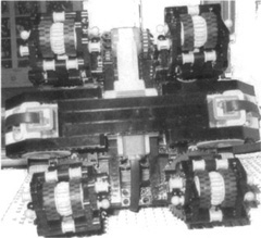
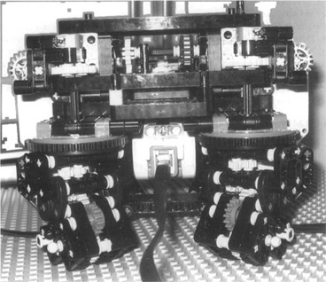
Figure 9.25 shows a side view of the same platform: You can see here that each turntable top portion (gray) is connected to the stationary part of the robot. This allows the bottom (black) section to be turned. The common drive motor geartrain can be seen with the gears and chain drive (top middle), then each of these transfers into a worm drive, then to a 24T gear, then down an axle into the center of the turntable. This mechanism is what sets it in motion.
Regarding a synchro drive robot, there is no real “front,” “back,” or “sides.” Because it can turn on the spot, the front simply becomes the side that is moving forward. However, for programming, you can arbitrarily pick a side that you consider the “front” to provide something to start with.
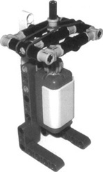
Synchro drives are quite amazing to see in action, and yours will be no exception. But if you expect it to navigate the room detecting obstacles, your challenge isn’t quite over yet: You still have to manage bumpers. Because there is no concept of “front” and “rear,” you have to place bumpers all around it. Or you could simply use a single omnidirectional sensor such as the one shown in Figure 9.26; the touch sensor is normally closed, but it opens whenever the upper axle departs from its default position (kept by the rubber bands). Note that the figure shown here was built as a sample for demonstration purposes. It is not complete and would require additional modifications to integrate fully into your robot. Surround your robot with a ring of tubes or axles, connect the ring to the omnidirectional sensor, and that’s it!
Our roundup doesn’t cover all the possible mobile configurations. There are other, more sophisticated or specialized types:
Multi-Degree-of-Freedom (MDOF) vehicles. MDOF vehicles have three or more wheels, or groups of wheels, both independently turned and driven. Imagine a synchro drive where each wheel can change its speed and direction with no connection to the others: Such a robot would be able to behave like a differential drive, a steering drive, or a synchro drive just by controlling its configuration from the software. Though interesting to study and very versatile in their use, they are also extremely difficult to build and control. In fact, not all of their possible configurations result in a coordinated motion!
Articulated drive. This is very similar to the steering drive, but instead of steering the wheels, it steers a whole section of the vehicle. The front wheels always remain parallel to the front part of the chassis, and the same applies to the rear wheels in regard to the rear portion of the chassis. Nevertheless, the two sections connect through an articulation point that lets them pivot in the middle. This configuration is common in wheeled excavators and other construction equipment.
Pivot drive. Keith Kotay defines a pivot drive as a configuration made of a chassis with nonpivoting wheels with a platform in the middle that can be lowered or raised. When the platform is up, the robot moves perfectly straight on its wheels. When it requires turning, it stops and lowers the platform until the wheels don’t touch the ground anymore. At this point, it rotates the platform to change its heading, and then raises the platform again and resumes a straight motion.
Tri-Star wheel drive. The Tri-Star configuration has been designed for high-mobility, all-terrain vehicles. Each “wheel” is actually an equilateral triangle with wheels in each vertex; the vehicle features three of them for a total of 12 wheels. The wheels turn, and the triangles can also turn like larger wheels. During normal motion, two wheels of each triangle touch the ground, but when a wheel sticks against an obstacle, a complex gearing system transfers motion to the triangular structure, which turns and places its upper wheel past the obstacle. As complicated to build as it is interesting!
Killough platform. Developed by Francois Pin and Stephen Killough, the official name of this mechanical configuration is Omnidirectional Holonomic Platform (OHP). Holonomy is the capability of a system to move toward any given direction while simultaneously rotating. Although conventional wheeled vehicles aren’t holonomic at all, this platform allows for unprecedented mobility. Seen from the top, a Killough drive shows three wheels placed at the vertices of an equilateral triangle. Each “wheel” is a sort of sphere made of actual wheels combined together and used in a quite unconventional way: on their side! For a nice demonstration of this, check out Steve Hassenplug’s OMNI (Appendix A).
We hope we’ve made you curious about these configurations, and we invite you to find out more about them using the reference material provided in Appendix A. You can build all of them from LEGO parts, and they’ll give you further challenges for when the standard configurations shown in this chapter have become old hat.
This chapter was quite dense, but we hope we were able to help you to choose a drive configuration. When building a mobile robot, different architectures are relevant to its resulting shape and, most important, to its performance.
The differential drive is simple and versatile, but it can’t go straight. The steering drive, meanwhile, goes straight but cannot turn in place. The skid-steer drive can do both, but its drive is not as smooth. Robotics is like cooking: There are many recipes for the same dish, but to be successful you still must know the ingredients well and use them in the right proportions. Of course, don’t forget to add the most important ingredient of all: your creativity.