
Solutions in this chapter:
One of the most important components of a robot is the sensor. The primary purpose of a sensor is to allow the robot to interact with its environment and perform actions based on feedback from its surroundings. This process is called autonomy, which by definition means freedom from external law. An autonomous robot is a self-governing device that takes input from its sensors and makes decisions based on this input. This tends to be the difference between those battle-bots you see on TV which are controlled remotely and an NXT sumo-robot that has to maintain its position within a ring while trying to push its opponent out.
Since the advent of the LEGO MINDSTORMS Robotics Invention System (RIS) in 1998, a significant demand has developed for aftermarket sensors. With the initial release of the RIS, it was difficult at first to find aftermarket sensors, and many people were stuck with the touch, rotation, and light sensors included with the kit. Few were honored to have a set of the Cybermaster touch sensors that allowed for sensor multiplexing.
The introduction of the LEGO MINDSTORMS NXT has changed this. Not only is the NXT compatible with most legacy RCX sensors such as the light, rotation, temperature, and touch sensors, but also it is compatible with the numerous aftermarket sensors that started to make their debut near or at the time of release of the NXT product (more are still to come). In fact, at the time of this writing, more than 15 aftermarket sensors and communication adapters were available from third-party vendors.
Out of the box, the NXT comes with the standard light and touch sensors, and has added the new ultrasonic and sound sensors as well as built-in motor encoders (rotation sensors) to the three servo motors. This chapter will look at these NXT sensors with a focus on the new additions as well as a variety of third-party sensors. We will also look at the new PC digital interface as well as some other unique aspects of the NXT system.
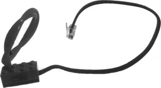
The sensor interface of the NXT system has changed significantly. At first glance, you will notice that LEGO added an additional sensor port (there are now four ports). The wiring for sensors and motor connections has changed as well. It now uses a six-wire cable connector that uses an RJ-12-like connector that features an offset locking latch and is smaller than the standard RJ-12. These wires allow the NXT to support legacy analog, passive, and newer digital sensors via the PC interface.
This custom connector is used to ensure that someone does not inadvertently try to connect his NXT to his telephone jack, or to a network hub. It is also used because the I2C interface has specific dedicated wires that must be plugged in one way only. LEGO has dedicated each wire as follows:
Pins 1 and 2 have the same functionality as the legacy RCX sensor cables which enable the NXT to read values from the touch, light, sound, and other legacy analog sensors. Note that you can get converter cables for legacy sensors from many third-party vendors, or you can make your own, such as the one detailed on Phillip Hurbain’s Web site (see Appendix A).
Pin 3 is grounded.
Pin 4 provides a constant voltage (~ 4.3 V).
Pins 5 and 6 are used to communicate with the digital sensors via the PC serial bus. The ultrasonic, color, and digital compass sensors (to name a few) are accessed using this method.
The I2C interface is a multimaster serial computer bus developed in the 1980s by Philips Semiconductor. It was initially used to connect low-speed peripherals to motherboards, embedded systems, and so on. It’s likely that the computer you are using right now has some form of PC implemented, such as hardware to read its CPU temperature.
The NXT brick has an PC communication channel for each of the four input ports. The PC serial bus uses pins 5 and 6—with pin 5 carrying the clock signal and pin 6 carrying the data signal. The NXT acts as the “master,” always invoking communications, and the sensor acts as the slave. This system supports up to 128 different slaves (or addresses). Can you imagine the possibilities? How about a combination of 128 motors and sensors, all multiplexed on the same port? Don’t sweat it; these ideas are already being addressed with third-party sensor suppliers such as HiTechnic and Mindsensors. Both have created sensor and motor multiplexers.
The general communication flow is as follows:
The master (NXT) initiates communications with the slave (sensor).
The master sends a start message with an address, and then sends a command.
The master waits for a reply.
The slave responds.
The master reads the response and code provides further actions for the robot.
LEGO used PC for the ultrasonic programming block in NXT-G (LEGO’s NXT graphical programming software). At the time of this writing, new custom PC NXT-G sensor blocks have been appearing weekly on fan-related blogs (e.g., www.nxtasy.org) that are opening up NXT-G to allow for custom sensor integration into this graphical development environment. RobotC has PC functionality built in, with many samples already available; you simply need to know the memory address locations of the registers from which to read the sensor results, which are typically provided by the vendor that is selling the sensor. In most cases, vendors also have sample code that you can use to get started.
Note
NXT-G is the programming environment LEGO provides with the NXT set. It is developed by National Instruments and provides you with a graphical interface for programming your NXT robot. It is easy for people of all ages to use to program their robots. Chapter 7 provides more detail on NXT-G as well as other third-party development platforms.
I2C integration on the NXT allows you to add digital devices to your robots. Digital devices have the added advantage of being able to include parameters such as device names, configuration parameters, calibration information, and so on. This makes these devices smart and allows for additional devices to be developed to the same standard. It also allows them to be chained much in the same way that USB devices can be chained with USB hubs.
LEGO chose to implement PC on the NXT, which has opened the door for a variety of sensors that will work with the NXT. I2C is one of the most significant improvements to the MINDSTORMS NXT and will open the door for a plethora of sensors, devices, and communications adapters for years to come. Now you will be able to make that 28-motor walking robot that you always dreamed of!
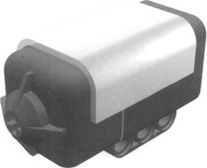
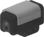
The touch sensor (see Figure 4.1) is probably the simplest and most intuitive member of the LEGO sensor family. Other than having the NXT “look,” not much has changed with this sensor. The most notable difference is a migration to the three-hole studless connection and the axle slot on the front. It works more or less like the pushbutton portion of your doorbell: When you press it, a circuit is completed and electricity flows through it. The NXT is able to detect this flow, and your program can read the state of the touch sensor
One of the sensor’s most common applications is to act as a bumper. Bumpers are a simple way of interacting with the environment; they allow your robot to detect obstacles when hit, and to change its behavior accordingly.
In NXT-G the sensor block has three states: pressed, released, and bumped. These are important, as they enable you to determine how your robot will react in different situations. For example, envision a robot that uses the sensor to detect the passing of an object on a conveyor. If that object gets stuck, the sensor state remains “pressed”; if it passes, the state is “bumped.” You could program your robot such that it reacts to “pressed” by reversing the conveyor temporarily to get the object unstuck. Alternatively, in RobotC, you would build a function that watches the sensor. Once pressed, it would monitor the time that it remains pressed. If this time exceeds a predefined limit, you could trigger your robot to react accordingly. This method works particularly well in sumo-robot competitions. You configure the sensor to detect when you are in contact with your opponent. When the sensor state is pressed, you continue in the direction you were going, and maybe even power up the motors, assuming you are pushing your opponent out of the ring.
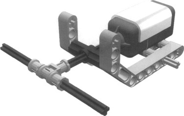
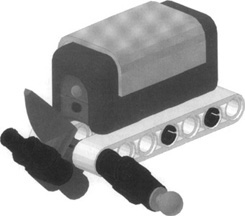
A bumper typically is a lightweight mobile structure that actually hits the obstacles and transmits this impact to a sensor, closing it. You can invent many types of bumpers, but their structure should reflect both the shape of your robot and the shape of the obstacles it will meet in its environment. A very simple bumper, such as the one in Figure 4.2, could be perfectly fine for detecting walls, but might not work as expected in a room with complex obstacles, such as chairs. In such cases, try experimenting. Design a tentative bumper for your robot and move it around your room at the proper height from the floor, checking to see whether it can detect all the possible collisions. If your bumper has a large structure, don’t take it for granted that it will impact the obstacle in its optimal position to press the sensor. Our example in Figure 4.2 is actually a bad bumper, because when contact occurs, it hardly closes the sensors at the very end of the traverse axle. It’s also a bad bumper because it transmits the entire force of the collision straight to the switch, meaning an extremely solid bracing would be necessary to keep the sensor mounted on the robot.
Be empirical. Try different possible collisions to see whether your bumper works properly in any situation. You can use the built-in touch sensor test program on the NXT brick which will display the status of the sensor on the LCD, or write a very short program that loops forever, producing a beep when the sensor closes, and use it to test your bumper.
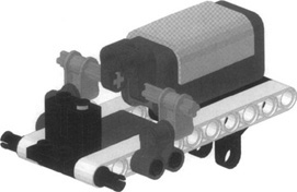
When talking of bumpers, people tend to think they should press the switch when an obstacle gets hit. But this is not necessarily true. They could also release the switch during a collision. Look at Figure 4.3. The rubber bands keep the bumper gently pressed against the sensor; when the front part of the bumper touches something, the switch gets released.
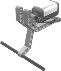
Actually, there are some important reasons to prefer this kind of bumper:
Because of its ability to be connected via studless beams, the new NXT touch sensor is sturdier than the legacy RCX one. However, you still want to minimize the impact force on parts. With this setup, the force doesn’t transfer to the sensor itself.
The rubber bands absorbing the force of the impact preserve not only your sensor, but also the whole body of your robot. This is especially important when your robot is very fast, is very heavy, is very slow to react, or possesses a combination of these factors.
Bumpers are a very important topic, but touch sensors have an incredible range of other applications. You can use them like buttons to be pushed manually when you want to inform your NXT of a particular event. Can you think of a possible case? Actually, there are many. For example, you could press a button to order your NXT to “take a reading of the ultrasonic sensor now,” and thus test distance readings. Or you could use two buttons to give feedback to a learning robot about its behavior, good or bad. The list could be long.
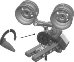
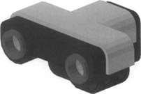
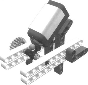
Another very common task you’ll demand from your sensor is position control. You see an example of this in Figure 4.4. The rotating head of our robot mounts a touch sensor that closes when the head looks straight ahead. Your software can rely on timing to rotate the head at some level (right or left), but it can always drive back the head precisely in the center simply waiting for the sensor to close.
There would be many other possible applications in regard to position control. What matters here that you explore many different approaches before actually building your robot. Let’s create another example to clarify a bit. Suppose you’re going to build an elevator. You obviously want your elevator to stop at any floor. You may think of having a switch at every level, so when one of them closes, you know that the cab has reached that level. Okay, nice approach. There’s one small problem, however; you have just one sensor, and an elevator with only two floors doesn’t seem like such an interesting project to you. You could buy more sensors, but this simply pushes your problem one floor up, without solving the general case. Meanwhile, you have used up most of the input ports of your NXT. Suddenly, an idea occurs to you: Why not put the sensor on the booth instead of on the structure? With a single sensor on the booth, and pegs that close it at any floor, you can provide your elevator with as many floors as you like. You see, by reversing our original approach, you found a much better solution. Are the two systems absolutely equivalent? No, they aren’t. In the first, you could determine the absolute position of the booth, and in the second, you are able to know only its relative position. That is, you do need a known starting point, so you can deduce the position of the cab counting the floors from there. Either requires that the cab be at a specific level when the program starts, or that it use a second sensor to detect a specific floor. For example, place a sensor at the ground level so that the very first thing your program has to do when started is to lower the elevator until it detects the ground level. From then on, it can rely on the cab sensor to detect its position.
Now your elevator is able to properly navigate up and down. You have one last problem to solve: How do you inform your elevator which floor to go to? Placing a touch sensor at every floor to call the elevator there is impractical. What could you do with a single sensor? Can you apply the previous approach here too?
Yes. You can count the pushes on a single touch sensor. For example, three clicks means third floor, and so on. Now you are ready to actually build your elevator! Of course, with the advent of the integrated encoders in the NXT servo motors, this approach has limited appeal. Later we will show you how you can address the same challenge with a single servo motor to both move the elevator and detect which floor it is on.
Saying that the light sensor (Figure 4.5) “sees” is definitely too strong a statement. What it actually does is detect ambient (surrounding) light and measure its intensity. But in spite of its limitations, you can use it for a broad range of applications.
The most important difference between the touch sensor and the light sensor is that the latter returns many possible values instead of a simple on/off state. These values depend on the intensity of the light that hits the sensor at the time you read its value. In both NXT-G and RobotC, default settings return values in the form of percentages ranging from 0 to 100. However, in RobotC you can also read the sensor in Raw mode. This allows for a higher degree of granularity, returning values ranging from 0 to 1,023.
When reading the sensor, the more light there is, the higher the percentage will be. What can you do with such a device? A possible application is to build a light-driven robot, a light follower as it’s called, that looks around to find a strong (or the strongest) light source and directs itself toward it. Provided that the room is dark enough not to produce interference, you could then control your robot using a flashlight.
This ability to trace an external light source is interesting, but it’s probably not the most amazing thing you can do with this sensor. There is another feature of this device: Not only does it detect light, but it emits some light as well. A small red LED provides a constant source of light, thus allowing you to measure the reflected light that comes back to the sensor. Both NXT-G and RobotC allow you to set the sensor to generate light (or not).
To illustrate the concept of measuring reflected light, let’s prepare an experiment. Take your NXT, turn it on, attach a light sensor to any input port, and configure the port properly using the built-in test program on the NXT. Configure the sensor as Reflected Light and set the port. Do a quick test. The red LED should illuminate. Prepare the environment. You need a dark room, not necessarily completely dark, but there should be as little light as possible. The NXT sensor test program allows you to view the value of a sensor in real time on the LCD screen. Run the test program to begin viewing the sensor value. Now you can proceed. Put the sensor on the table. Take some LEGO bricks of different colors and place them one by one at short distances from the sensor (about 0.5 inches, or 1 to 1.5 cm). Keep all of them separated from each other at the same distance, and look at the readings. You will notice how different colors reflect a different amount of light (you might want to write down the values on a sheet).
For the second part of the experiment, take the white brick and move it slowly toward the sensor and then away from it, always looking at the values in the display. You see how the values decrease when you increase the distance. You can find a distance where the white brick reads the same value you have read for the black one at a shorter distance. You cannot tell the distance and the color at the same time, but if you know that one of the properties doesn’t change, you can calculate the other. It’s important to stress again that in both cases, you must do your best to shield your system from ambient light.
Probably the most widespread usage of the light sensor is to make the robot read lines or marks on the floor where it moves. This is a way to provide artificial landmarks your robot can rely on to navigate its environment. The simplest case is line follotving. The setup for this project is very simple, which is one of the reasons it’s so popular. Despite its apparent simplicity, this task deserves a lot of attention and requires careful design and programming. Pay attention to what happens when the sensor “reads” a black line on a light floor.
When the sensor is on the floor, it returns, say, 70 percent, whereas on the black line, it returns 30 percent. If you move it slowly from the floor to the line or vice versa, you notice that the readings don’t leap all of a sudden from one to the other. They go through a series of intermediate values. This happens because the sensor doesn’t read a single point, but rather a small area in front of it. So when the sensor is exactly over the borderline, it reads half the floor and half the black strip, returning an intermediate result.
Is this feature useful? Well, sometimes it is, and sometimes it’s not. When dealing with line following in particular, it is very useful. In fact, you can (and should) program your robot to follow the “gray” area along the borderline rather than the actual black line. This way, when the robot needs to correct its course, it knows which direction to turn: If it reads too “dark,” it should turn toward the “light” region, and vice versa.
When you need to navigate a more complex area—one, for example, that includes regions of three different colors—things get more difficult. Imagine a pad divided into three fields: white, black, and gray. How can you tell the gray area from the borderline between the white and the black areas? You can’t, not from a single reading, anyway. You must take into consideration other factors, such as previous readings, or you can make your robot turn in place to make it gather more information and understand where it is. To handle a situation such as this, your software is required to become much more sophisticated.
Of course, with the advent of aftermarket sensors such as the HiTechnic color sensor, variable colored line following may become more feasible. More on this later.
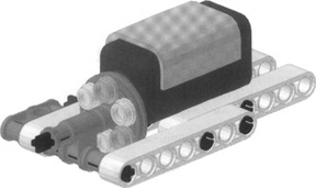
The light sensor is such a versatile device that you can imagine many other ways to employ it. You can build a form of proportional control by placing a multicolored movable block of LEGO parts in front of it. Figure 4.6 shows an example of this kind. When you push or pull the upper side of the beam, the sensor reads different light intensities.
Combining the light sensor with a lamp brick (not included in the NXT kit) you get a photoelectric cell (Figure 4.7); your robot can detect when something interrupts the beam from the lamp to the sensor. Notice the double-split TECHNIC axle joiner in front of the sensor to reduce the possible interference from ambient light.
One of the most anticipated additions to the NXT is the ultrasonic sensor (sometimes referred to as the sonar sensor). This sensor had its origins as a third-party add-on sensor developed by HiTechnic for the RCX. The idea of using sound to detect obstacles was popular enough that LEGO decided to make this sensor a standard part of the NXT kit. Figure 4.8 shows the sensor.
The principle behind ultrasonic detection is that the sensor emits high-frequency ultrasound (beyond the limit of human hearing), which bounces off objects and is read back by the sensor. The time that each pulse takes to bounce back to the sensor determines the distance from it. The longer the interval, the further the object is, and vice versa. Bats use the same principle as a means of navigating and of locating their prey. The technique is called echolocation and allows bats to distinguish between an insect and a falling leaf. Now there is a challenge to try with your NXT!
A common way to program the sensor is to set it up to constantly poll the environment, and then use the value returned to enable your robot to react (e.g., steer away, or back up). In both NXT-G and RobotC, readings are normalized, returning values between 0 and 100. NXT-G allows these to be set in inches or centimeters. RobotC also supports raw, un-nor-malized readings; however, most just use the normalized values.
Here is a sample RobotC ultrasonic test program:
while(true)
{
nDist = SensorValue(sonarSensor);
nxtDisplayTextLine(1, "Distance:%d", nDist) ;
waitl0Msec(l00);
eraseDisplay();
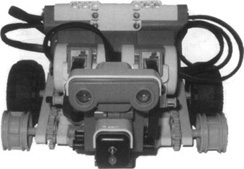
}Try to build yourself a robot that can navigate a room without bumping into objects. Figure 4.9 shows a sample robot built to test the ultrasonic sensor using a simple four-wheel drive skid-steer loader platform.
This is the first sensor from LEGO to implement the I 2C interface described at the beginning of this chapter. Through NXT-G, LEGO developed the sensor block to read the I2C messaging and interpolate the values to provide a distance reading in inches or centimeters.
When choosing which sensor to use, you should remember the advantages and limitations of each sensor type. In particular, the ultrasonic sensor has a wide range and is capable of working with all lighting conditions (because it relies on sound only). On the other hand, its beam is relatively wide (about 30 degrees), so even point objects appear broad when you scan around with it. The IR sensors based on SHARP sensor technology (such as the new Mindsensors.com IR sensor) have a narrow beam, giving better spatial resolution, but are more sensitive to light conditions. Furthermore, the two sensor types have different “tastes” with respect to target materials—ultrasound is absorbed by soft materials, making them invisible to the ultrasonic sensor, whereas a mirror would reflect ultrasound back to the sensor but prevent IR sensor detection.
Previously with the RCX, users who wanted to perform proximity detection were stuck with limited options. One option was to purchase a third-party proximity sensor such as the Techno-Stuff Dual Infrared Proximity Detection (DIRPD) sensor. This sensor, combined with a language such as NQC, could be programmed to detect left, right, and center obstacles and proved very effective at navigation and obstacle avoidance. To demonstrate its effectiveness, look at the WallFollower robot at www.plastibots.com. Another option was to use the standard light sensor with the RCX IR communication feature. With some NQC code, one could program the RCX to send pulses of IR and have the light sensor read these. The timing of response for them would yield a distance reading.
The introduction of the ultrasonic sensor to the NXT provides similar functionality out of the box. Through NXT-G, you can quickly write a simple program that can be used to detect obstacles in front of your robot and have it react accordingly. You can try doing this yourself by building TriBot from the NXT-G Robo Center and configuring it such that the sensor is used to avoid obstacles as it drives around.
Fans such as Guy Ziv (at www.nxtasy.org) have gone a step further and taken advantage of the PC interface to use the sensor in “ping” mode. What does this mean? Well, out of the box, you really can use one of these sensors on only one robot at a time. If you try to configure two ultrasonic sensors to run at the same time, both sensors get initialized when the program starts, each will emit ultrasound at the same time and cause confusion between readings due to bouncing signals between them.
To solve this, Guy used a custom block in NXT-G by configuring two sensors on the same robot and having the software alternate (at a rapid pace) the sending and reading of ultrasound for each sensor. The general process is as follows:
Ultrasonic Sensor 1: Send signal (ping), read result, store value.
Ultrasonic Sensor 2: Send signal (ping), read result, store value.
Compare both values and react accordingly.
If you have two ultrasonic sensors, you can get into developing some sophisticated proximity detection with your robot. You could use them to better decide which side of your robot an obstacle is on, or use the values to produce a “radar” type of map on the NXT display to do some environment mapping.
The legacy RCX rotation sensor was always known for its lack of reliability with readings when turning at both low and high speeds. Robot makers had to play with code to provide stability to readings returned from this sensor.
LEGO decided to integrate an encoder (rotation sensor) directly within its new NXT servo motors (Figure 4.10). There are two benefits to this: The encoder functionality was improved, and the NXT received three rotation sensors built right into the motors that don’t require additional sensor ports! The interactive servo motor (as it’s also referred to) allows you to measure both speed and distance in a variety of formats, including degrees, rotations, and seconds. It acts as both a motor and a rotation sensor, and has a dedicated block for each of these in NXT-G. In RobotC, you would simply set the parameters for driving the motor as you normally would while using other commands to read the encoder values to measure rotation.
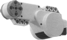
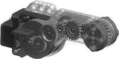
Figure 4.11 shows an internal view of the servo motor with the encoder (in blue) located to the left of the larger orange drum (the motor). In reality, the encoder is actually a black wheel that contains 12 holes which allow the optical sensor to read 24 on/off states with each full rotation. This provides the NXT with a great deal of resolution to detect position down to the nearest degree. From the image, you can also see how the NXT motor is internally geared. There is enough torque to drive wheels/tracks directly. Even though the RIS motors are also internally geared, they have limited torque that usually required an additional geartrain—especially in sumo competitions!
Having an encoder built directly into the servo motor allows robot designers to develop more sophisticated drive mechanisms that enable your robot to do things such as drive straight, even over rough terrain. This functionality works out of the box with NXT-G. When you program your robot, the move block pairs two motors together, enabling the NXT to monitor the encoders of both motors while correcting them on the fly to ensure that the robot is tracking straight. The general idea is that the program monitors rotations on both motors. If one falls behind, it adjusts the speed of one motor to compensate for the lag, which keeps the robot driving straight.
You can try this yourself by creating the TriBot from within Robo Center (sample robots in NXT-G). Following the programming guide, you will use a move block to allow for both drive motors to be synchronized. Once built, run the robot and follow along beside it. Press your finger to one of the wheels and then let go. Note how at first you slow down one side of the robot, but then it speeds that side up to bring the robot back to driving in a straight line.
As mentioned earlier, you can use a single servo motor to both move an elevator as well as determine which floor it is on. With the new level of accuracy in these motors, you can determine the position of the elevator by performing some simple tests to find which angle values represent each floor. To do this, create the elevator unit and manually rotate the motor while viewing the encoder rotation values in NXT-G (or the RobotC poll brick window). Jot down the rotation angle for each floor. Then, simply identify in your program these angles as stop points for the elevator unit.
The encoder functionality is very powerful for the future of NXT robots, as it opens the door by enabling your robots to be “location-aware” by performing tasks such as room mapping. The sky is the limit here.
Bricks & Chips...
How the Servo Motor Encoder Works
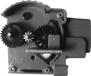
The NXT motor encoder detects movement similar to the way an older computer mouse (with the ball) works. One of the first things Philippe Hurbain (Philo) did when he got his NXT set was to dismantle the servo motors to have a look under the hood. His site (see Appendix A) provides detail on this. Figure 4.12 shows the motor and encoder components cut away from the rest of the motor. The encoder wheel (the black wheel to the right) is driven directly off the motor. The wheel has a number of holes in it which allow the optical sensor to detect on/off states as it spins. A beam of light is generated from the optical sensor (the gray square box covering the encoder wheel) on one side of the encoder wheel and shines through to the other, which falls upon a photocell. As the motor spins, the encoder rotates and causes light to alternate through a series of on/off states. The sensor picks this up and passes the information to the NXT for processing. Unlike the older rotation sensor, because the motor is directly coupled to the encoder wheel, direction is automatically handled, as the NXT always knows which way it is driving the motor based on the programming done in the software.
Through RobotC, it is possible to detect motor stall conditions by monitoring the motor encoder rotation as your motor turns. Knowing the power and expected output of the motor, you can match this with the speed at which the encoder is actually turning and detect when the motor has stopped turning. This has an added bonus, as you could conceivably create a robot that does not need a touch sensor to detect when it has hit a wall. You can simply monitor the motor rotations and judge it this way—when you hit a wall, you can detect that the motors have either slowed or stopped, and after a period of, say, one or two seconds, force a decision to back up or turn.
Note
The NXT supports three types of sensors: passive, active, and digital. The main difference is that passive sensors do not require a current generator to supply power to the sensor, whereas active sensors do. Digital sensors use PC communication and typically have a microcontroller to handle sampling of the environment.
Passive sensors include the touch sensor (NXT and RCX), light and sound sensors (NXT), and the RCX temperature sensor. Active sensors include the RCX light and rotation sensors. Digital sensors include the NXT ultrasonic sensor and numerous third-party sensors such as color, compass, pressure, gyro, and acceleration sensors.
Sooner or later, you will probably find yourself without the proper sensor for a particular project. For instance, you need three touch sensors, but you have only one. Is there anything you can do? There’s no way to turn any sensor into a light sensor or a temperature sensor, but touch and rotation sensors are at some level replaceable.
Even with the addition of an extra sensor port on the NXT, there are still times when builders need additional ports. There are aftermarket solutions, such as sensor multiplexers, but these can be expensive, especially if you want to do this for only one robot or to test an idea. In the following sections, you’ll find some common and well-tested tips that can help.
There’s a long list of possible alternatives to the rotation sensor. All the suggested methods are based upon counting single impulses generated by a rotating part. They all work well, but usually they don’t detect the direction of rotation. In many cases, this is not a problem, because when coupled with a motor you know which direction your sensor is moving. Of course, with the addition of three rotation sensors with the NXT, the need for something such as this is more limited now than it was for the RCX. However, it is still important to show ideas on how, with some simple parts, you can emulate other sensors.
The assembly pictured in Figure 4.13 shows an axle with aTECHNIC knob wheel that closes a touch sensor. Each complete rotation would account for four “ticks” on the sensor. If geared properly, this could provide a decent resolution for determining the state of a component of a robot. For example, you could use it to determine which floor an elevator is at by counting the number of ticks per floor. This is the principle: Use either a cam or any other suitable part that, while rotating, periodically pushes the sensor.
Making a rotation sensor out of a light sensor is not very different: Build some kind of rotating disk with sectors of different colors, and count the transitions from one color to the other (Figure 4.14). The general tip applies to this case too: Try to insulate the sensor from external light sources as much as possible.
Other LEGO electric devices, though not actual sensors, can be successfully employed to emulate a rotation sensor. These are typically available from sources such as BrickLink and are not hard to find.
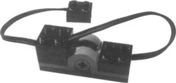
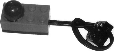
One such device is the polarity device. Connect it as shown in Figure 4.15, and configure it as a touch sensor. With every turn, it closes the circuit twice. Note that you would need an NXT converter cable, as this uses the older RCX connection.
After the RIS came out, some people found that they needed more than the three sensor ports provided on the RCX. Expansion of sensor ports on the RCX was limited to touch sensor multiplexers such as the one developed by Techno-Stuff (Figure 4.16).
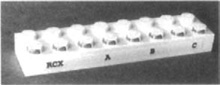
The principle behind its construction is based on wiring the sensors in a series and with each connection having a resistor wired between each sensor connector and the port labeled “RCX.” All that would be needed is an RCX-to-NXT converter cable to enable your robot to work with it. For each connector, the resistor would vary in rating. In the case of the Techno-Stuff multiplexer, the resistors are 62K, 30K, and 15K. The RCX sensor port would be set to read raw data (light sensor) and the values returned would vary depending on which sensor or sensor combination was clicked. This was quite powerful, as you could sense eight combination sensor states for three sensors on one port.
If you were lucky enough to own a LEGO CyberMaster 8482 set, you had three touch sensors that already had variable resistance built in. All you needed was a unique cable configuration (Figure 4.17) that would allow the NXT to see each sensor separately. Reading these sensors as raw (light sensor) would allow you to read varying resistance values depending on which sensor combination was pressed.
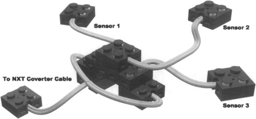
In Figure 4.17, you can see a number of RCX cables connected to each other, as well as running off to each sensor. The purpose of this is to have the wiring such that the sensors are connected in parallel to each other. This wiring allows the NXT to detect all the combinations sensors being pressed by the electrical resistance being returned to the NXT port. If you want to know more about how this works, look on the Internet for Ohm’s Law.
A bit has changed with the NXT. If you have legacy sensors and multiplexers, you could probably connect them to your NXT, but you will need a converter cable to go from the NXT to the RCX connector. However, a number of new sensor multiplexers are on the horizon. Both HiTechnic and Mindsensors are in the running and have products in the works.
With the advent of the I2C interface, the line between motor and sensor multiplexing has been blurred a bit. Both HiTechnic and Mindsensors have something in the works here. Because this chapter is focused on sensors, we won’t go into detail on the motor multiplexers. Generally speaking, they are similar to what will be described here, with the difference being that they are used to drive multiple motors off one motor port on the NXT.
HiTechnic has a sensor multiplexer (Figure 4.18) that connects to a single NXT sensor port, allowing four additional sensors to be connected. This allows seven sensors to be connected at once. Imagine what you can do with four of these! The PC interface is the foundation for all of this and enables the device to handle any combination of any sensor type, including light, ultrasonic, compass, color, pressure, and other PC sensors. It also supports legacy sensors using the converter cable.
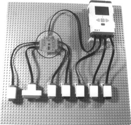
Fans of the original MINDSTORMS line will be the first to tell you that the inclusion of a fourth sensor port on the NXT is a welcome addition. Some believe that four is still not enough, but with the introduction of the rotation sensors in the servo motors and sensor multiplexers, fans have far more options now to build complex robots with single NXT units. Of course, one could always buy another NXT and use Bluetooth communications to enable them to think together. But that is a discussion for another chapter.
Although this chapter is focused on sensors, you may be interested in having a look at the Mindsensors motor multiplexer in Chapter 3. It acts in a similar way to the aforementioned sensor multiplexer, but it allows you to control four additional motors from one NXT sensor port and it uses the I2C interface.
In the months after the release of the MINDSTORMS RIS, a whole new market for addon sensors opened up. The introduction of the NXT in 2006 has propelled this market to new highs. Currently a handful of aftermarket companies, such as HiTechnic, Mindsensors, and Techno-Stuff, are actively marketing sensors for the NXT (and RCX).
The NXT is backward-compatible with most legacy RCX sensors, which provides users with a wide array of choices for additional sensors. Currently a number of sensors are available for both the NXT and the RCX, ranging from pressure, tilt, gyro, color, passive infrared, motor/sensor multiplexers, compass, IR communication, acceleration, and sound sensors (to name a few). There has even been discussion about GPS integration! There is not enough room to cover all these sensors in this chapter, or it would become a book itself! However, we will look at some of these to give you a taste of what is out there. If you don’t see something here, a quick search of the Internet for LEGO sensors or NXT sensors will give you a night’s full of reading.
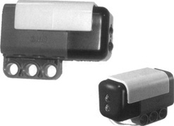
The passive infrared (PIR) sensor (Figure 4.19) by Techno-Stuff was originally intended for use with the RCX. However, you can also use it with the NXT using a converter cable. The PIR sensor detects passive infrared radiation (heat sources). Remember the movie Predator? Remember how the alien “saw” the soldiers it was hunting? The PIR sensor “sees” heat much in the same way. You can use this sensor to build a robot that can seek out heat sources not evident to the human eye.
You can configure the PIR sensor as a light sensor in either NXT-G or RobotC. Readings will indicate detection of an object in front of it. The sensor technology has a 20-foot range and a 180-degree swath. The infrared technology used in this sensor is different from TV remote controls, so they will not interfere with it.
If you have this sensor, you can try setting up a small program that plays a sound when you wave objects in front of it. First try moving something cool to the touch, such as an unfilled glass or cup—you should not get any results, as it is not giving off much (if any) infrared radiation. Now try moving your hand in front of the sensor—you should hear a sound. Your results may vary depending on the level of infrared being given off by your hand. During tests, the sensor was quite effective at detecting people walking in front of it from a few feet away, but it did nothing when it was right in front of a wall or door (as expected).
Can you think of an idea for using this sensor on your robot? How about making a robot that can follow your pet around? Or how about a robot that can find a small light source (such as a light bulb) in a maze? Note that you should not use a candle or open flame for such a test, as that is a fire hazard. Stick to things that are safe!
Pneumatics plays an important role in many robot builders’ designs and creations. For more detail on this, look at Chapter 11, as it discusses the use of pneumatics with the NXT. Integrating pneumatics into NXT robots can be both exciting and challenging at the same time, as you are combining motor, gear, and drive systems with pneumatic cylinders to perform varying tasks.
In some cases, you may find the need to use pneumatics for things such as hand claws or providing motion. In other cases, it is necessary to maintain a state of constant pressure and to monitor it so that compressed air is available when needed. The same principle is used in air compressors that you can buy at your local hardware store. A compressor usually has a motor, sensor, piston, and tank to store compressed air. When started, the compressor turns on and begins filling the tank, until at some point, the sensor detects that there is enough air pressure in the tank, which tells the motor to stop pumping. In these compressors, the sensors can be simple mechanical triggers, or electronic sensors.
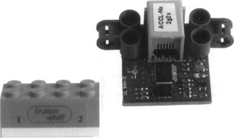
Figures 4.20 and 4.21 show two pressure sensors developed by Mindsensors andTechno-Stuff. They are both very similar in operation and specifications. The main difference is how the product is presented and its mounting approach. Mindsensors tends to go with the raw PCB approach, but also provides standard TECHNIC pin holes for mounting to your robot. Techno-Stuff provides the sensor electronics stuffed into a traditional LEGO brick, and you can mount the sensor the same as you would any LEGO 2 x 4 brick.
Uses for this sensor vary in different designs. One such idea would be to connect it inline to a pneumatic circuit via a T-junction air tube. Your robot design would likely include a pump, storage tank(s), and pneumatic piston (s), with the sensor being linked to the system to monitor the air pressure. While the robot is operational, some of the air is lost through switches and junctions (which are not perfectly sealed). This sensor can be used to monitor the pressure and trigger a motor pump to switch on to refill the storage tanks.
Programming it as a light sensor would allow the NXT to monitor the pressure and trigger the compressor motor on or off based on a preset threshold, thus ensuring that enough air is in storage and ready for the robot to perform its tasks.
Think of some other ways you can use a pressure sensor. How about using it inline on a robotic claw? Here’s the idea:
Build a claw hand to grab objects and use the sensor to measure pressure feedback as the claw grabs the object.
Use a motor to open/close the claw and to mount a pneumatic piston inline on one side—a sort of “spring-loaded” finger.
Mount the pressure sensor inline with the pneumatic piston so that movement in the piston directly causes a change in the readings of the pressure sensor.
As the claw closes on the object, the pneumatic piston will compress as the grip gets tighter.
Use the values returned to provide feedback. For example, you could have the NXT play sound tones depending on how hard it is gripping. Or you could code the grabbing motor to close the claw only so much, depending on the amount of desired pressure.
Measurement of the change in velocity of an object is called acceleration. When an object goes from a standstill to moving, its velocity changes and it begins to accelerate. When that object slows, its velocity is reduced and therefore it is decelerating. Acceleration sensors are useful for measuring changes in movement of a robot, detecting when it is tilting (for balance), determining whether it is climbing a hill, or going down, and so on.
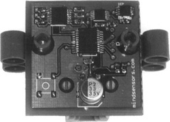
Numerous acceleration sensors are on the market for use with the NXT system. Techno-Stuff offers a two-axis sensor that you can use for both the RCX and the NXT. HiTechnic offers a three-axis sensor that allows acceleration measurement in the x-, y-, and z-axes. Mindsensors is also in the game here, offering a variety of two- and three-axis sensors with varying sensitivities ranging to +/- 5 G. Figure 4.22 shows a variety of these sensors.
There are varying types of accelerometers, including piezo electric, surface microma-chined capacitive (MEMS), thermal, and electromechanical (to name a few). The technology behind an accelerometer is quite simple. In the case of MEMS, for each axis a tiny polysilicon structure is suspended above a silicon wafer via a polysilicon spring. Together, they form a differential capacitor with the wafer below. Gravity keeps the suspended structure hovering at a specific location; when the sensor is moved, the acceleration causes the suspended structure to move relative to the fixed structure below it, which causes a change in capacitance. This change is measured and converted to values that are used by the software.
Specific programming approaches for these sensors depend on which version you have. Each supplier offers samples for you to work with in both NXT-G and RobotC. HiTechnic has an NXT-G acceleration sensor block that allows you to read x-, y-, and z-axis values. Mindsensors provides RobotC sample code using the I2C bus.
When using these sensors on your robots, there are some considerations you have to be aware of to ensure reliable readings. Some robot designs cause the robot to “jolt” when moving (especially when starting and stopping), which you will have to account for when programming your sensor. This “jolting” effect may be enough to cause the sensor to return erroneous readings that, if not programmed correctly, could trigger a reaction when you don’t desire one. To address this, you can write your sensor reading functions in such a way as to smooth out the values.
For example, let’s say you are building a sumo robot that can detect when it is about to be flipped over and you are using the acceleration sensor to detect tilt and initiate a reaction. If you simply take each reading (say, every 200 ms) and use that value to react, you may find your robot reacting unnecessarily due to its own driving actions. Instead, you can write a routine that will take (for example) 20 readings, every 10 ms to 20 ms apart, and then average the values to return a more reliable result. This way, for the brief moment that the sensor received a few erroneous readings, they will be averaged with the 18 correct readings which will allow your robot to interpret and ignore this. When your robot does get hit by its competitor, most (if not all) of the readings will be suggesting a hit and then it can react appropriately.
It is also important to consider mounting locations. If you want to have a highly sensitive response, mount the sensor on a long antenna-like contraption. Each small movement at the base will be translated into a larger movement at the sensor. If you desire a less sensitive response, mount the sensor close to your robot’s center of gravity (the base), away from motors and other mechanisms that will cause vibration.
So, what can you build with an acceleration sensor? How about a weigh scale? Or a robot that has self-leveling, separately tracked wheel drive units where the base keeps itself parallel to the ground? Because the sensor uses gravity to measure tilt, you can do things such as detect when your robot is going uphill, or know when it is accelerating too fast back down. You can even build a robot that shifts its center of gravity forward as it climbs to give it more holding power and better balance.
As technology advances, robots are becoming more advanced than they have ever been before. Providing the capability for a robot to become “location-aware” takes us one step closer to robots that will be able to know where they are and navigate their environment based on an internal “map” database of its surroundings.
There has been some discussion about integrating GPS receivers into NXT robots, but although they are accurate, they are not (currently) accurate enough to provide the resolution to navigate, say, a room with chairs and tables. This also does not take into consideration GPS signal quality issues indoors. One would have to spend tens of thousands of dollars to get a GPS device that could return something even close to the requirements here.
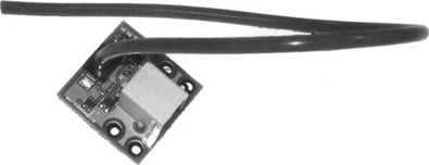
One solution for providing location awareness is dead reckoning. This process begins with a known position, or “fix.” Then the robot will proceed to navigate by recording its movement. The problem is you can only really record time, distance, and speed. Although the NXT servo motors allow for precise tracking of the robot’s direction, they can’t tell you when the robot has actually slipped on a slick floor or loose terrain. This is where the heading comes in. A compass sensor will provide a means to do this (see Figure 4.23).
A compass sensor is not affected by the interaction between the robot wheels and the ground. It uses the Earth’s magnetic field to determine the position (heading) of the sensor. These values are converted into measurements in one-degree resolution for use by the NXT.
Adding a compass sensor into the mix while performing dead reckoning allows you to track heading along with other parameters. Together, these values would provide you the means to record your robot’s actions and allow for them to be played back. Conceivably, you could build a robot that records time, distance readings, speed, and heading values to a file, and then reads the file to have it navigate back along the track it just took. There is a challenge that will keep you busy for a night.
Mindsensors has developed an NXT-to-RCX bidirectional communication adapter (Figure 4.24) to allow users with RCX programmable bricks to control them using the NXT. You can also use the adapter to control some LEGO IR-based sets such as the 7897 Passenger Train set. Although this device is not actually a sensor itself, it connects to a sensor port and provides a means to link the NXT to other devices that use infrared for communications and control.
The NrLink adapter uses the I2C interface and protocols for communication on the NXT. The device has a number of configuration parameters, such as user-selectable short/long-range IR signal communication with the RCX, and because it is developed using I2C, it can also coexist with other LEGO or third-party digital sensors on the same port.
Using supplied sample code, you can easily connect to an RCX within range, and issue commands to run programs, motors, start/stop tasks, and so on. So, if you have an older RCX brick and want to expand the functionality of your NXT kit, this device may provide you with that extra needed expansion. Have a look at Chapter 3, as it shows a sample using this sensor to communicate to the LEGO Power Function IR interface, which will allow you to expand motor control via an unwired connection. This is quite useful when creating robots where you can’t afford to have cables tangle up.
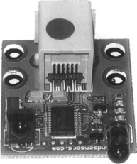
The HiTechnic Color Sensor (Figure 4.25) is one of the more welcome additions to the line of aftermarket sensors for the NXT. For both the RCX and the NXT, robot builders were pretty much limited to receiving variations of black-and-white values using the provided light sensor. This sensor changes all that by allowing your robot to see a variety of colors.
The color sensor uses three different colored LEDs to illuminate the surface of objects. It reads the intensity of each color reflected back, and the variation of this intensity for each color enables it to determine the color of the object. The sensor uses the PC interface to communicate with the NXT and returns the color number (0-17). It also returns the raw and normalized red, blue, and green values so that you can customize the response based on exact readings (custom code is required for this).
With these options, you may think the sensor offers limitless possibilities. Although it does offer enough possibilities for most uses, it is important to note that this sensor is affected by ambient light similar to the way the stock light sensor is. More important, in order to get an accurate reading, you should place the sensor directly above (or in front of) the object it is reading, and it must be close to the object (approximately 1 cm). One reason for this is that reading the object at close range reduces the chances of ambient light entering the equation; in addition, this requires less power.
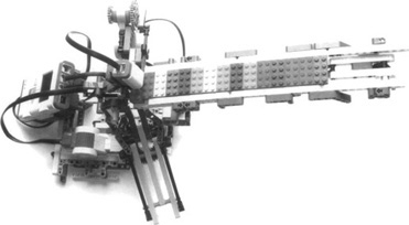
What can you do with a color sensor? How about building a brick sorter? Surely every LEGO robot builder wishes he could have a robot help him sort his LEGO bricks. This sensor will help you on your way to achieving that goal. Figure 4.26 shows Brick Sorter (www.plastibots.com). It demonstrates how you can use the sensor to read the color of a LEGO brick and provide a color to allow the NXT to sort it into the correct container. With some additional tweaking, it would be fairly easy to enhance this robot to also sort gears, pins, and so on.
This sensor offers many more possibilities than just allowing you to sort LEGO bricks. Can you think of an idea for how to use this sensor? How about using it for line following in a multicolored line-follower competition? You haven’t heard of such a competition? Why not try to create one yourself? Just get some colored tape and lay it down on the floor. To make it more challenging, have some colored tape crisscross and see whether your robot can determine the correct path to travel. Then, once you figure it out, try to see how fast you can make your robot do the circuit.
In this chapter, we’ve introduced you to a number of sensors, including the standard NXT sensors (touch, sound, light, ultrasonic, and servo motor encoder) as well as a number of sensors provided by third-party suppliers. Their basic behavior is easy to understand, but here you’ve discovered that if you want to get the very most out of them, you must understand their requirements and limitations. The touch sensor, for example, seems to be a simple device, but with some clever work on your part, it can become an important tool for counting clicks, or it can make a good bumper.
You were also introduced to the implementation of the PC communications interface to the NXT. This feature has opened the doors for endless sensor/motor control possibilities with the NXT and external devices. People have been interfacing all sorts of sensors and controllers to the NXT, and more are yet to come. There has even been discussion of connecting the NXT to GPS receivers or similar devices to make NXT robots location-aware.
Another notable addition to the NXT system is the sound sensor, which allows your robot to interact with the environment by “listening.” There is also the addition of the ultrasonic sensor, which has opened the door to building robots that are able to react before they hit an object. The integration of a rotation sensor to each of the three NXT servo motors provides your robot with precise motor control for things such as driving and positioning. More important, the NXT effectively has the capability to run with seven sensors out of the box (four sensor ports and three servo motor encoders).
Sensors are an important part of robot design and functionality. Remember to think outside the box with each challenge you are faced with. If you require multiple touch sensors for a robot, but you have only one, think of another way you can meet the requirement. As discussed in this chapter, you can use a light sensor to act as a touch sensor.
Numerous aftermarket sensors are available for the NXT, and more are coming. If, for example, you are looking to expand motors or sensors on your NXT, you don’t have to buy another NXT. Instead, have a look at the various multiplexers available out there. Stay tuned, as there are more cool sensors to come that we could not talk about here due to nondisclosure restrictions.